EP2118433B1 - Spinner apparatus - Google Patents
Spinner apparatus Download PDFInfo
- Publication number
- EP2118433B1 EP2118433B1 EP08709663A EP08709663A EP2118433B1 EP 2118433 B1 EP2118433 B1 EP 2118433B1 EP 08709663 A EP08709663 A EP 08709663A EP 08709663 A EP08709663 A EP 08709663A EP 2118433 B1 EP2118433 B1 EP 2118433B1
- Authority
- EP
- European Patent Office
- Prior art keywords
- roller
- bogey
- rollers
- spinner apparatus
- spinner
- Prior art date
- Legal status (The legal status is an assumption and is not a legal conclusion. Google has not performed a legal analysis and makes no representation as to the accuracy of the status listed.)
- Active
Links
- 238000009987 spinning Methods 0.000 claims description 16
- 238000000034 method Methods 0.000 claims description 12
- 230000003213 activating effect Effects 0.000 claims description 2
- XEEYBQQBJWHFJM-UHFFFAOYSA-N Iron Chemical compound [Fe] XEEYBQQBJWHFJM-UHFFFAOYSA-N 0.000 description 14
- 230000000712 assembly Effects 0.000 description 9
- 238000000429 assembly Methods 0.000 description 9
- 239000012530 fluid Substances 0.000 description 7
- 229910052742 iron Inorganic materials 0.000 description 7
- 239000000463 material Substances 0.000 description 3
- 241000239290 Araneae Species 0.000 description 2
- 238000005266 casting Methods 0.000 description 2
- 238000006243 chemical reaction Methods 0.000 description 2
- 238000011109 contamination Methods 0.000 description 2
- 238000005553 drilling Methods 0.000 description 2
- 238000012423 maintenance Methods 0.000 description 2
- 230000004913 activation Effects 0.000 description 1
- 239000008186 active pharmaceutical agent Substances 0.000 description 1
- 230000008901 benefit Effects 0.000 description 1
- 230000008859 change Effects 0.000 description 1
- 239000011248 coating agent Substances 0.000 description 1
- 238000000576 coating method Methods 0.000 description 1
- 230000008878 coupling Effects 0.000 description 1
- 238000010168 coupling process Methods 0.000 description 1
- 238000005859 coupling reaction Methods 0.000 description 1
- 238000003780 insertion Methods 0.000 description 1
- 230000037431 insertion Effects 0.000 description 1
- 238000009434 installation Methods 0.000 description 1
- 238000004519 manufacturing process Methods 0.000 description 1
- 230000007246 mechanism Effects 0.000 description 1
- 238000003801 milling Methods 0.000 description 1
- 238000005096 rolling process Methods 0.000 description 1
- 230000003068 static effect Effects 0.000 description 1
Images


Classifications
-
- E—FIXED CONSTRUCTIONS
- E21—EARTH DRILLING; MINING
- E21B—EARTH DRILLING, e.g. DEEP DRILLING; OBTAINING OIL, GAS, WATER, SOLUBLE OR MELTABLE MATERIALS OR A SLURRY OF MINERALS FROM WELLS
- E21B19/00—Handling rods, casings, tubes or the like outside the borehole, e.g. in the derrick; Apparatus for feeding the rods or cables
- E21B19/16—Connecting or disconnecting pipe couplings or joints
- E21B19/168—Connecting or disconnecting pipe couplings or joints using a spinner with rollers or a belt adapted to engage a well pipe
Definitions
- the present invention is directed to spinner apparatus for connecting and disconnecting tubular members (for example casing, tubing, pipe, or drill pipe) and, in certain particular aspects to spinners, spinning wrenches, spinning tongs, iron roughnecks and methods of their use.
- tubular members for example casing, tubing, pipe, or drill pipe
- Drill pipe introduced into a well during oil and gas wellbore drilling is assembled in lengths joined with threaded joints. As the pipe is fed into a well, the sections of pipe are threaded together. When removing pipe, the threaded sections are disconnected and the sections of pipe stored. Inserting and removing the sections of drill pipe into a well is called "tripping.” Threading and unthreading sections of pipe on tripping in and out of the well can be a difficult and cumbersome job. To make up the threads (or unscrew or break the threads) requires relatively high torque (rotational force). "Spinning" the pipe section after breaking (or before making up) the joints requires much less torque and is accomplished at much higher speed.
- Tightening and breaking joints requires a wrench to be tightly clamped on the pipe.
- tightening and breaking was done manually with hand wrenches (more recently with power assisted wrenches).
- Spinning is a separate operation, long ago and in some places today done by wrapping a chain around a pipe and pulling the chain with a winch.
- Today power tong wrenches are used. Certain of these tongs have an open slot for pipe insertion and hydraulically powered clamps to grip the pipe. The pipe is rotated by a motor mechanically attached to the wrench.
- Such wrenches can develop high torque and work very well for making and breaking thread joints.
- Usually these wrenches work in combination with a backup wrench that holds the other section of threaded joint.
- a gripping device known as a spider in a floor of an oil or gas platform is primarily used to prevent the string of tubulars from falling down the well.
- the spider can be used as a backup to react against the torque of a wrench making or breaking a joint and spinning.
- the wrench is removed after making or breaking the threads, and a spinner (or top drive unit) spins out the threaded joint.
- Such wrenches are exemplified by the description in U.S. Patent 4,348,920 .
- Iron roughnecks which combine a torque wrench and a spinning wrench, have been used for connecting and disconnecting various tubulars, for example drilling components, such as drill pipe, in running a string of drill pipe or other pipe into or out of a well.
- the prior art includes a variety of iron roughnecks; see for example U.S. Patents 4,023,449 ; 4,348,920 ; 4,765,401 ; 6,776,070 , Document US 2005/0056122 is considered the closest prior art in which pairs of rollers are mounted on movable arms.
- FIG. 1 Various prior art iron roughnecks have a spinning wrench and a torque wrench mounted together on a carriage.
- a torque wrench For making or breaking threaded connections between two tubulars, for example joints of drill pipe, certain iron roughnecks have a torque wrench with two jaw levels.
- An upper jaw of the torque wrench is used to clamp onto a portion of an upper tubular, and a lower jaw clamps onto a portion of a lower tubular, for example upper and lower threadedly connected pieces of drill pipe.
- the upper and lower jaws After clamping onto a tubular, the upper and lower jaws are turned relative to each other to break or make a connection between the upper and lower tubulars.
- a spinning wrench mounted on the carriage above the torque wrench, engages the upper tubular and spins it until it is disconnected from the lower tubular (or in a connection operation, spins two tubulars together prior to final make-up by the torque wrench).
- Certain iron roughnecks are mounted for movement from a wellbore center to a retracted position which does not interfere with or block performance of other operations relative to the well and rotating or driving apparatuses.
- Such a prior art system can be used for making and breaking joints in a main string or for connecting to or disconnecting from a tubular section located apart from a wellbore center, for example in a mousehole (or rathole) at a side of a well.
- Certain prior art iron roughneck systems include a carriage for rolling on the surface of the rig floor along a predetermined path.
- a spinner and torque wrench are mounted for upward and downward movement relative to a carriage, for proper engagement with tubulars, and for tilting movement between a position in which their axis extends directly vertically for engagement with a vertical well pipe and a position in which the axis of the spinner and torque wrench is disposed at a slight angle to true vertical to engage and act against a pipe in an inclined mousehole.
- a spinner is movable vertically with respect to a torque wrench.
- a spinner apparatus for facilitating connection and disconnection of threaded tubulars, the spinner apparatus comprising a first roller and a second roller characterised in that the first roller has a projection and the second roller has a recess, when in use, at least part of the projection is located within at least part of the recess.
- the projection contacts the tubular, which may be provided with a contact material such as non-marking material which increases the surface energy between the roller and the tubular to reduce the chance of slippage therebetween.
- the first and second rollers are each generally cylindrical having a circular cross-section, the projection projecting around the circumference thereof.
- the projection may be a continuous ring around the roller, preferably forming a ring of constant diameter and most preferably concentric with the roller.
- the projection may be formed by forming a recess in the roller.
- the recess may be formed by milling material from the roller.
- the projection may have an outer coating suitable for gripping a tubular to reduce slippage therebetween to reduce the possibility of marking the tubular and increase the speed of spinning.
- the outer most point of the projection preferably does not touch the base of the recess, leaving a small gap therebetween.
- the outer most point of the projection touches the base of the recess.
- each roller has a surface area and the rollers are movable to contact the tubular with each roller having a similar amount of surface area in contact with the tubular.
- the spinning apparatus has a central axis and the rollers are positioned parallel to the central axis and are movable at a right angle to the central axis.
- the second roller comprises at least two projections, the recess formed therebetween.
- the first roller comprises at least two recesses and the at least one projection formed between the at least two recesses.
- the at least two projections of the first roller interleave with the at least one projection of the second roller.
- the diameter of the first roller (61,361) is equal to the diameter of the second roller.
- the first roller comprises a plurality of projections and the second roller comprises a plurality of projections, the plurality of projections of the first roller interleave with the plurality of projections of the second roller.
- the first roller is arranged on a bogey.
- the bogey is a passive bogey, in that it is free-floating, preferably, about a pin and most preferably free-floating about the pin for ten degrees of movement.
- the bogey comprises a further roller.
- the further roller has at least one projection interleaving with the at least one projection of the first roller.
- the bogey is pivotally arranged on an arm.
- the arm is movable by activation of a piston and cylinder to move the bogey towards and away from a tubular to be spun.
- the second roller is arranged on a bogey.
- the bogey is an active bogey.
- the bogey is directionally controllable, preferably by a pin arranged in a slot.
- the slot controls the angle of the bogey.
- the slot has a sharp kink.
- the bogey comprises a further roller (62,362).
- the further roller has at least one projection interleaving with the at least one projection of the first roller.
- the bogey is pivotally arranged on an arm.
- the arm is movable on a piston and cylinder.
- the spinner apparatus further comprises a further piston and cylinder, the further piston and cylinder linked to the piston and cylinder with a flexible union.
- the flexible union comprises at least one of a ball and socket and the piston assembly comprises the other of the ball and socket.
- the arm is linked to a body, the free-floating union movable in relation to the body.
- the first and second roller are driven by motors.
- each rotor is driven be its own motor.
- the recess is a groove, may be a continuous groove about the perimeter of the roller.
- the present invention also provides a spinner apparatus for facilitating connection and disconnection of threaded tubulars, the spinner apparatus comprising a first roller on a first arm and a second roller on a second arm, the first and second arms movably linked to a body characterised in that , a first and second piston and cylinders are arranged between the first and second arms, wherein ends of the piston and cylinders meeting at a free-floating union, in use the piston and cylinders are activated to move the arms to move the first and second rollers into and out of engagement with a tubular to be spun.
- the free-floating union is preferably guided by a guide, which may be attached to the body.
- the body advantageously comprises a frame.
- the end comprises a hemispherical bearing each first end mounted on a first, and each second end mounted in a second hemispherical bearing so that each of the powered cylinder apparatus is substantially isolated from lateral loading.
- the present invention also provides an apparatus for facilitating connection and disconnection of threaded tubulars, the apparatus comprising a spinner apparatus of the invention and a torque apparatus for torquing a connection between the threaded tubulars.
- the spinner apparatus and the torque apparatus are fixed together on a upright beam.
- the present invention also provides a method for facilitating connection and disconnection of threaded tubulars, the method comprising the steps of activating a spinner apparatus to move at least first and second rollers into contact with the tubular, the first roller comprising at least one projection and the second roller comprising at least one recess, the projection locating in at least part of the recess of the second roller and rotating at least one of the first and second rollers to spin at least one of the threaded tubulars.
- the present invention in certain embodiments, provides an apparatus for rotating a tubular, the apparatus including a plurality of adjacent driven rollers which can be interlaced to accommodate tubulars with a range of diameters.
- Such an apparatus may have a motor for each set of rollers.
- this configuration of motors with interlacing rollers permits axes of adjacent motors to be relatively closer resulting in a more compact tool.
- the interlacing facilitates maintenance of spacing apart of the rollers around a tubular and helps prevent the rollers from slipping on a tubular or from spitting a tubular out the front of the system.
- the spinner apparatus can be made more compact, whilst maintaining the ability to spin a range of diameters of tubulars.
- FIGS 1A to 1H show a spinner apparatus 10 in accordance with the present invention which has a main frame 12 with a crossmember 13 connecting two spaced-apart upright beams 14 releasably connected by chains 16 to a hanging bracket 18.
- Clamping cylinder assemblies 20 disposed between frame members or plates 22, 24 move arms 26, 28 which, in turn, move bogeys 30, 32 to move rollers mounted thereon (described below) into contact with a tubular to be rotated.
- Tubulars can include pipe, drill pipe, tubing, liner and casing.
- Each arm 26, 28 includes a top plate (26a, 28a) and a bottom plate (26b, 28b).
- any part or piece or component that includes multiple items for example (but not limited to) a component with multiple plates, to instead be made as a single integral component, for example a casting.
- a part with multiple plates connected together, for example welded together may be a single manufactured casting.
- Chains or cables connected to torque reaction links 34, 36 releasably connect the spinner apparatus 10 to a support column or other structure (see also link 34, Figure 2D ).
- Optional covers 41 - 44 shield motors 51 - 54 which rotate rollers 61 - 64.
- the arms 26, 28 are pivotably secured to trunnions 23, 25 of trunnion blocks 27, 29.
- An end 31, 33 of each cylinder assembly 20 is rotatably secured by a pin 35 to a cylinder mount 37.
- the pin 35 is arranged substantially vertical, such that each end 31, 33 of the cylinder assembly is rotatable in a substantially horizontal plane.
- the plates 22, 24 have slots 21a, 21b (respectively - see Figures 1A , 2A ) in which a pin 39 moves.
- the pin 39 extends through a hole 73 in an upper plate 30a (shown in Figure 2B ), and a hole 74 in a lower plate 30b of the left hand bogey 30 to secure the left hand bogey 30 to the plates 22, 24.
- the slots 21a, 21b limit movement of the pin 39 thereby limiting movement of the left hand bogey 30. This also limits the movement of the rollers 63, 64 rotatably connected to the left hand bogey 30 (as described in detail below).
- Cover mount blocks 49 on the plate 30a provide structure to which the cover 43 is secured.
- the cover 44 is secured to the plates 26a, 26b.
- the left hand bogey 32 pivots about a pin 48.
- the pin 48 extends through holes 88 in the plates 26a, 26b.
- the right hand bogey 32 is "free floating" in the sense that it is not slaved to anything and can pivot, for example up to 10 degrees with respect to the center line of the spinner apparatus 10.
- the right hand bogey 32 is movable freely about a pin 45.
- the right hand bogey 32 has a top plate 32a and a bottom plate 32b.
- the pin 45 passes through holes 71, 72 (see Figure 2C ) to secure the right hand bogey 32 to the plates 22, 24.
- the cover 42 is secured to mount blocks 75.
- the cover 42 is secured to the arms 26, 28.
- the motors 53, 54 are on top of the left hand bogey 32 and the motors 51, 52 are on top of the right hand bogey 30.
- a flow divider 170 receives power fluid (for example hydraulic fluid under pressure from a rig source). Power fluid from the flow divider 170 is provided via connections 172 to the motors 51 - 54 and to the clamping cylinders 20.
- the motors 51 - 54 are located above corresponding rollers; but it is within the scope of the present invention to locate the motors at any convenient location whether above the rollers or not.
- the roller 62 is mounted with portions in the holes 76a, 76b (see Figure 2C ); the roller 61 is mounted with portions in the holes 77a, 77b; the roller 64 is mounted with portions in the holes 78a, 78b (see Figure 2B ); and the roller 63 is mounted with portions in the holes 79a, 79b.
- the pin 47 extends through a hole 94 in the plate 26a, through a hole (not shown) in the plate 26b and through a hole 87 in the plate 22 and a hole 88 in the plate 24 to pivotably connect the arm 26 to the plates 22, 24.
- the pin 46 extends through a hole 89 in the arm 28, through holes 85, 86 in the plates 22, 24 and through a lower hole 101 in the plate 28b to pivotably pin the arm 28 to the plates 22, 24.
- Figure 2E shows the arm 28 (the arm 26 is a mirror image of the arm 28).
- Figure 2F shows a bogey limiter 110 (see also in Figure 1A ) which prevents the bogey 32 from rotating more than a certain amount, for example within a 10 degree range of motion.
- the bogey limiter is deleted.
- FIGS 3A to 3F show a roller 120 and associated parts.
- the roller 120 may be any of the rollers 61, 62, 63, 64 (or any roller herein).
- the roller 120 has a body 122 with a plurality of spaced-apart projections 124 - 127.
- the projections have a series of spaced-apart grooves 128 or 129. It is believed that the projections with these grooves will function similarly to the treads of a tire on a wet surface and a surface film on the projections will be forced into the grooves thereby increasing friction between the rollers and a tubular to be rotated.
- the roller body 122 has a recess 139 and a slot 131 which receives a corresponding member 132 (into slot 131) and a corresponding end (into recess 139) of a drive spindle 133.
- the drive spindle 133 passes through an upper bearing housing 134.
- the drive spindle 133 is connected to a drive shaft of a motor (for example a motor 51 - 54).
- the motor rotates the drive spindle 133 which in turn rotates the roller 120.
- the motor can be bolted to the upper bearing housing 134.
- the roller 120 rotates on a lower spindle 135 which rotates in a lower bearing housing 136 whose bottom is covered with a cover 137.
- the upper bearing housing 134 and the lower bearing housing 136 are connected to a corresponding bogey (see any bogey in the spinner apparatus 10 shown in Figure 1A ).
- projections 124 - 127 are a series of spaced-apart areas 141, 142, and 143 and an area 144 beneath the lowermost projection 127. Projections on an adjacent roller like the projections 124 - 127 can be received in and fit within the areas 141 - 144 as two rollers are moved toward each other.
- the areas 141 - 144 are recessed with respect to the outer surfaces of the projections 124 - 127.
- a first roller to have one projection (or at least one projection) and an adjacent roller to have one groove (or at least one groove), with the one projection projecting into and received within the one groove so that the two rollers are interlaced (or for the at least one projection to project into the at least one groove or for each of a series of spaced-apart projections on a first roller to project into and be received within a corresponding groove of a series of spaced apart grooves on a second adjacent roller.
- a spinning wrench apparatus in accordance with the present invention can have two pairs of such rollers, the two pairs movable to contact each other so that a first roller of each pair interlaces with each other and a second roller of each pair interlaces with each other.
- Figures 1F to 1H illustrate movement of the arms 26, 28; the bogeys 30, 32; and the rollers 61 - 64 with respect to the frame 12 and with respect to a tubular T (see Figure 1H ).
- the pin 39 is at one end 21c of the slots 21a, 21b (end 21c of the slot 21a) which positions the rollers 63, 64 at an angle to a central axis A of the spinner apparatus 10 (for example in one particular aspect four degrees).
- the clamping cylinders 20 have not been actuated to move the arms 26, 28, the bogeys 30, 32 and the rollers 61 - 64 inwardly toward the tubular T.
- the clamping cylinders 20 have been actuated, pivoting the arms 26, 28 to move the bogeys 30, 32 and the rollers 61 - 64 moving the rollers 61, 62 toward the rollers 63, 64.
- the rollers 61, 63 are interlaced with each other with the projections on one roller received in the valleys of the other roller.
- the rollers 62, 64 are interlaced with each other with the projections on one roller received in the valleys of the other roller.
- the rollers 61, 62 are mounted so that they are interlaced with each other with the projections of one roller received in the valleys of the other roller; as are the rollers 63, 64.
- All of the rollers contact the tubular T and, when rotated, the rollers rotate the tubular T.
- the interlacing facilitates maintenance of spacing apart of the rollers around a tubular and helps prevent the rollers from slipping on a tubular or from spitting a tubular out the front of the system.
- the pin 39 has moved to an opposite end 21d of the slots 21a, 21b guiding the orientation of the bogey 30 and rollers 63, 64 at a desired location.
- the available stroke of the cylinders stops movement of the bogey 30 at a "clamp off” position or "clamp on without pipe” position.
- an axis B of the rollers 63, 64 is parallel to the axis A insuring the rollers are maintained horizontal to the central axis of the system at all times.
- the bogey pivot pins 45, 48 each will move through an arc while a theoretical pipe center remains in position relative to the system.
- each roller 61 - 64 has an equal amount of contact with the tubular T so that static clamp forces are applied equally by all four rollers, including those on the right hand bogey 32 (since the right hand bogey floats free, the left hand bogey allows all rollers to contact a tubular with equal force).
- rollers diagonal to each other have equal clamp force, but the leading and trailing rollers on each bogey have different contact force onto a pipe.
- Figures 4A and 4B are perspective views of the cover 41.
- Figure 5 shows an apparatus 200 in accordance with the present invention for connecting and disconnecting tubulars TB and TL while a spinner apparatus 210 (shown schematically) in accordance with the present invention spins the tubular TB a wrench 202 (for example any suitable wrench or tong) holds the tubular TL.
- a hanger 204 permits connection of the spinner apparatus 210 to another member or structure.
- the wrench 202 is connected to the spinner apparatus 210 with a connection 206 and a spring 208.
- the spinner apparatus 210 may include any spinner apparatus in accordance with the present invention, including but not limited to, that of Figure 1A or of Figure 7A .
- Figure 6 show an apparatus 10 in accordance with the present invention (like systems disclosed in co-owned U.S. Patents 7,185,547 and 7,062,991 ) which has a carriage 25 which is movably connected for up/down vertical movement to a column 14 and which can also translate horizontally on a rig floor RF for movement toward and away from a drill pipe D of a drill string DS in a well W.
- Support arms 22, 24 (two each) are pivotably connected at one end to a base 23 of the carriage 20. Optionally, only one support arm is used or two arms in parallel are used.
- a connector 21 is removably emplaceable in a socket 29 to mount the system on the rig.
- a torque wrench 11 (for example as disclosed in co-owned U.S. patents 7,185,547 and 7,062,991 , or in any prior art cited therein) and a spinner apparatus 10 (any in accordance with the present invention) are connected to the carriage 20 and are movable by a power mechanism PM toward and away from the column 14 by moving the support arms 22, 24.
- a known torque wrench may be used, for example instead of the torque wrench 100.
- the spinner is movable up and down on the spin wrench carriage 25 toward and away from the torque wrench.
- a control console CS for the spinner apparatus 10 is shown schematically in Figure 1B .
- the console CS communicates by wire or wirelessly with the torque wrench 100 and/or the spinner apparatus 10 and/or the control console CS is located remotely from it.
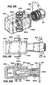
- FIGS 7A to 7H show a spinner apparatus 300 in accordance with the present invention which has a frame 312 with a crossmember 313 connecting two spaced-apart beams 314 releasably connected by connectors 316 to a hanging bracket 318.
- Clamping cylinder assemblies 320 disposed between frame members 322, 324 are connected to and selectively move arms 326, 328 which, in turn, move bogeys 330, 332 to move rollers mounted thereon (described below) into contact with a tubular to be rotated.
- Cylinder yoke bushings 334 of the clamping cylinder assemblies 320 received and held in corresponding holes 326h, 328h in plates 326a, 326b, 328a, 328b of the arms 32b, 328, respectively, to pivotably connect the arms 326, 328 to the clamping cylinder assemblies 320.
- a center member 321 connected to both clamping cylinder assemblies 320 is secured to a frame center mount 335. It is within the scope of the present invention to use a single cylinder assembly instead of the two cylinder assemblies 320.
- Each arm 326, 328 includes a top plate (326a, 328a) and a bottom plate 326b, 328b). These plates 326a, 326b, 328a, 328b are pivotably mounted to and between the frame members 322, 324 with pins 325.
- Covers 341 - 344 shield motors 351 - 354 and rollers 361 - 364 which are rotated by the motors 351 - 354.
- the bogeys 330, 332 are pivotably connected to the arms.
- the plates 322, 324 have slots 322a, 324a respectively in which a pin 339 moves.
- the pin 339 extends through a hole 373 in an upper plate 332a and a hole 374 in a lower plate 332b of the bogey 332.
- the slots 332a, 332b guide movement of the pin 339 thereby guiding movement of the bogey 332. This also guides the movement of the rollers 363, 364 rotatably connected to the bogey 332 (as described in detail below).
- Cover mount blocks 349 on the plate 332a provide structure to which the cover 343 is secured.
- the cover 344 is secured to the arm 328.
- the bogey 332 pivots about a pin 348.
- the pin 348 extends through holes 388 in the plates 328a, 328b.
- the bogey 330 is "free floating"" in the sense that it is not slaved to anything and can pivot with respect to the arm 326 and can pivot, for example up to 10 degrees, with respect to the center line of the system.
- the bogey 330 freely pivots about a pin 345.
- the bogey 330 has a top plate 330a and a bottom plate 330b.
- the pin 345 passes through holes 371, 372 to secure the bogey 330 to the arm 326.
- the cover 341 is secured to mount blocks 375.
- the cover 342 is secured to the arm 326.
- the motors 353, 354 are on top of the bogey 332; and the motors 351, 352 are mounted on top of the bogey 330.
- a flow divider 370 receives power fluid (for example hydraulic fluid under pressure from a rig source). Power fluid from the flow divider 370 is provided via connections 372 to the motors 351 - 354. Power fluid from the flow divider 370 is provided to the clamping cylinder assemblies 320 via connections 374.
- the motors 351 - 354 are located above corresponding rollers; but it is within the scope of the present invention to locate the motors (or a single motor or two motors) at any convenient location whether above the rollers or not, below the rollers, or adjacent the rollers; or to use a single motor for driving multiple rollers, for example, but not limited to, a first motor for driving the rollers on one side, for example via appropriate gearing, and a second motor for driving the rollers on the other side.
- One motor can drive multiple rollers, for example via gearing, in synchronization.
- the roller 362 is mounted with portions in the holes like holes 76a, 76b (see Figure 2C ); the roller 361 is mounted with portions in the holes like 77a, 77b (see Figure 2C ) ; the roller 364 is mounted with portions in the holes like holes 78a, 78b (see Figure 2B ); and the roller 63 is mounted with portions in the holes 79a, 79b.
- a pin 347 extends through holes in the plates 322, 324 and through holes in the plates 326a, 326b to pivotably connect the arm 326 to the plates 322, 324.
- a pin 346 extends through holes in the plates 328a, 328b and through holes in the plates 322, 324 to pivotably connect the arm 328 to the plates 322, 324.
- the rollers 361 - 364 may be like any roller disclosed herein in accordance with the present invention (for example, but not limited to, the rollers shown in Figures 1A and 3C ).
- the roller 363 has a plurality of spaced-apart projections 377 and a plurality of spaced-apart recesses 379.
- Any of the rollers 361 - 364 may have grooves like the grooves 128 or 129 described above.
- the rollers 361 - 364 may have the associated parts as shown in Figures 3A - 3F .
- the clamping cylinder apparatuses have been activated to move the arms 326, 328, bogeys 330, 332, and rollers 361 - 364 inwardly to clamp a tubular T for spinning.
- the pin 339 has guided the rotation of the bogey 332 about the pivot pin 348.
- the pin 337 prevents the bogey from trying to rotate in the opposite direction to the rollers 363 and 364.
- the pin 339 slides along the slots 332a, 324a as the clamp cylinders are operated, but it is the end stroke of the clamp cylinders and not the slots that limit the extremes of clamping movement.
- the bogey 332 can be considered as the "master” while the bogey 330 is the “slave”.
- the bogey 332 aligns the spinner unit precisely with the tubular centerline irrespective of the tubular diameter.
- the bogey 330 then passively self aligns as clamp force is applied.
- the rollers 361 - 364 are interlaced as shown in Figures 7E - 7 H .
- the roller 361 interlaces with the roller 362 and with the roller 363.
- the roller 362 also interlaces with the roller 364.
- the roller 364 interlaces with the rollers 362 and 363.
- interlacing of rollers works like treads on a tire; i.e. contact area is reduced and local contact pressure is increased, while surface contamination tends to be pressed into the grooves.
- each clamping cylinder assembly 320 has a housing 320a within which a piston 320p is movably mounted.
- a pivotable connector 320c connects the piston 320p to the center member 321.
- the connector 320c has a first member 320d with a ball end 320e and a second member 320f with a ball end 320g.
- a pin 320h pins an end 320i of the second member 320f to the first member 320d.
- the ball end 320e of the first member is movable in a first spherical bearing 320j connected to the piston 320p.
- the ball end 320g is movable in a second spherical bearing 320k connected to the center member 321.
- the members 320d, 320f act like a rod connected to the piston 320p.
- the housing 320a is pivotable with respect to the housing center member 321, allowing the cylinder to accommodate a certain amount of both angular and parallel misalignment without transferring significant loads to the cylinder slides and seals.
- the fixed cylinders using the hemispherical bearings 320e, 320g are substantially or almost totally isolated from side loads (for example loads perpendicular to a longitudinal axis of the members 320d, 320f which could create a moment which would be resisted by sliding surfaces of the piston).
- side loads for example loads perpendicular to a longitudinal axis of the members 320d, 320f which could create a moment which would be resisted by sliding surfaces of the piston.
- side or lateral loads can be the result of wear of moving parts; production or installation tolerances; mechanical deflection under loading; or incorrect operation.
- a seal 320m (for example, but not limited to, a rubber bellows apparatus) seals the housing-320a-center-mount-321 interface and prevents moisture and contamination from reaching the connector system and ball joints.
- a retaining ring 321a screwed onto the center member 321 locks the ball end of the connector to the center member 321 to retain the spherical bearing 320k and resists cylinder retract loads when pressure is applied to the return side of the piston (pressure in the volume space 320x).
- Pressurized oil from the flow divider 370 enters a cylinder retract port 320w to move the housing inwardly to unclamp the rollers from a tubular.
- the rollers are applied by supplying pressurized oil from the flow divider 370 to the rear of the piston via one of the two cylinder extend ports 320r. Channels 320s within the body of the cylinder lead this oil to the rear of the piston. Oil within the space 320x is pressed out of the cylinder retract port as the cylinder extends.
Abstract
Description
- The present invention is directed to spinner apparatus for connecting and disconnecting tubular members (for example casing, tubing, pipe, or drill pipe) and, in certain particular aspects to spinners, spinning wrenches, spinning tongs, iron roughnecks and methods of their use.
- Drill pipe introduced into a well during oil and gas wellbore drilling is assembled in lengths joined with threaded joints. As the pipe is fed into a well, the sections of pipe are threaded together. When removing pipe, the threaded sections are disconnected and the sections of pipe stored. Inserting and removing the sections of drill pipe into a well is called "tripping." Threading and unthreading sections of pipe on tripping in and out of the well can be a difficult and cumbersome job. To make up the threads (or unscrew or break the threads) requires relatively high torque (rotational force). "Spinning" the pipe section after breaking (or before making up) the joints requires much less torque and is accomplished at much higher speed. Tightening and breaking joints requires a wrench to be tightly clamped on the pipe. In the early days, tightening and breaking was done manually with hand wrenches (more recently with power assisted wrenches). Spinning is a separate operation, long ago and in some places today done by wrapping a chain around a pipe and pulling the chain with a winch. Today power tong wrenches are used. Certain of these tongs have an open slot for pipe insertion and hydraulically powered clamps to grip the pipe. The pipe is rotated by a motor mechanically attached to the wrench. Such wrenches can develop high torque and work very well for making and breaking thread joints. Usually these wrenches work in combination with a backup wrench that holds the other section of threaded joint. A gripping device known as a spider in a floor of an oil or gas platform is primarily used to prevent the string of tubulars from falling down the well. However, in some circumstances, the spider can be used as a backup to react against the torque of a wrench making or breaking a joint and spinning. The wrench is removed after making or breaking the threads, and a spinner (or top drive unit) spins out the threaded joint. Such wrenches are exemplified by the description in
U.S. Patent 4,348,920 . Some types of these wrenches lack the capacity of handling different diameter pipe without changing pipe clamps. Since drill pipe, couplings, tapered pipe and joints are of different diameters, some wrenches handle widely varying diameters from about 9cm to about 25cm (3.5 to about 9.5 inches) in diameter. It is a great advantage for a wrench to be able to accommodate a range of diameters without having to change the clamps.U.S. Patent 4,979,356 is an example of a power tong wrench which can not only accommodate the desired range of pipe diameters, but is also capable of making and breaking pipe sections and spinning the pipe. The ability to do both with the same wrench is highly desirable since it accomplishes with one connection step what previously required two or more connections with a wrench and spinner. - "Iron roughnecks," which combine a torque wrench and a spinning wrench, have been used for connecting and disconnecting various tubulars, for example drilling components, such as drill pipe, in running a string of drill pipe or other pipe into or out of a well. The prior art includes a variety of iron roughnecks; see for example
U.S. Patents 4,023,449 ;4,348,920 ;4,765,401 ;6,776,070 , DocumentUS 2005/0056122 is considered the closest prior art in which pairs of rollers are mounted on movable arms. - Various prior art iron roughnecks have a spinning wrench and a torque wrench mounted together on a carriage. For making or breaking threaded connections between two tubulars, for example joints of drill pipe, certain iron roughnecks have a torque wrench with two jaw levels. An upper jaw of the torque wrench is used to clamp onto a portion of an upper tubular, and a lower jaw clamps onto a portion of a lower tubular, for example upper and lower threadedly connected pieces of drill pipe. After clamping onto a tubular, the upper and lower jaws are turned relative to each other to break or make a connection between the upper and lower tubulars. A spinning wrench, mounted on the carriage above the torque wrench, engages the upper tubular and spins it until it is disconnected from the lower tubular (or in a connection operation, spins two tubulars together prior to final make-up by the torque wrench).
- Certain iron roughnecks are mounted for movement from a wellbore center to a retracted position which does not interfere with or block performance of other operations relative to the well and rotating or driving apparatuses. Such a prior art system can be used for making and breaking joints in a main string or for connecting to or disconnecting from a tubular section located apart from a wellbore center, for example in a mousehole (or rathole) at a side of a well.
- Certain prior art iron roughneck systems include a carriage for rolling on the surface of the rig floor along a predetermined path. In certain prior art systems a spinner and torque wrench are mounted for upward and downward movement relative to a carriage, for proper engagement with tubulars, and for tilting movement between a position in which their axis extends directly vertically for engagement with a vertical well pipe and a position in which the axis of the spinner and torque wrench is disposed at a slight angle to true vertical to engage and act against a pipe in an inclined mousehole. In certain prior art systems, a spinner is movable vertically with respect to a torque wrench.
- The prior art discloses a variety of tongs and spinners for use in wellbore operations, for example, but not limited to, as disclosed in and referred to in
U.S. Patents 6,684,737 ;6,971,283 ;5,660,087 ;5,161,438 ;5,159,860 ;5,842,390 ;5,245,877 ;5,259,275 ;5,390,568 ;4,446,761 ;4,346,629 ;4,221,269 ;3,892,148 ;4,023,449 ;5,044,232 ;5,081,888 ;5,167,173 ;5,207,128 ;5,409,280 ;5,868,045 ;6,966,385 ;6,138,529 ;4,082,017 ;6,082,224 ;6,213,216 ;6,330,911 ;6,668,684 ;6,752,044 ;6,318,214 ; and6,142,041 . - There is a need, recognized by the present inventors, for an efficient tubular spinning system which can effectively handle a range of tubulars with varying diameters.
- In accordance with the present invention, there is provided a spinner apparatus for facilitating connection and disconnection of threaded tubulars, the spinner apparatus comprising a first roller and a second roller characterised in that the first roller has a projection and the second roller has a recess, when in use, at least part of the projection is located within at least part of the recess. In use, the projection contacts the tubular, which may be provided with a contact material such as non-marking material which increases the surface energy between the roller and the tubular to reduce the chance of slippage therebetween.
- Preferably, the first and second rollers are each generally cylindrical having a circular cross-section, the projection projecting around the circumference thereof. The projection may be a continuous ring around the roller, preferably forming a ring of constant diameter and most preferably concentric with the roller. The projection may be formed by forming a recess in the roller. The recess may be formed by milling material from the roller. The projection may have an outer coating suitable for gripping a tubular to reduce slippage therebetween to reduce the possibility of marking the tubular and increase the speed of spinning. The outer most point of the projection preferably does not touch the base of the recess, leaving a small gap therebetween. Advantageously, the outer most point of the projection touches the base of the recess. Preferably, each roller has a surface area and the rollers are movable to contact the tubular with each roller having a similar amount of surface area in contact with the tubular. Advantageously, the spinning apparatus has a central axis and the rollers are positioned parallel to the central axis and are movable at a right angle to the central axis.
- Advantageously, the second roller comprises at least two projections, the recess formed therebetween. Preferably, the first roller comprises at least two recesses and the at least one projection formed between the at least two recesses. Advantageously, the at least two projections of the first roller interleave with the at least one projection of the second roller. Preferably, the diameter of the first roller (61,361) is equal to the diameter of the second roller.
- Preferably, the first roller comprises a plurality of projections and the second roller comprises a plurality of projections, the plurality of projections of the first roller interleave with the plurality of projections of the second roller.
- Advantageously, the first roller is arranged on a bogey. Preferably, the bogey is a passive bogey, in that it is free-floating, preferably, about a pin and most preferably free-floating about the pin for ten degrees of movement. Preferably, the bogey comprises a further roller. Advantageously, the further roller has at least one projection interleaving with the at least one projection of the first roller. Preferably, the bogey is pivotally arranged on an arm. Preferably, the arm is movable by activation of a piston and cylinder to move the bogey towards and away from a tubular to be spun. Advantageously, the second roller is arranged on a bogey. Preferably, the bogey is an active bogey. The bogey is directionally controllable, preferably by a pin arranged in a slot. Advantageously, the slot controls the angle of the bogey. Preferably, the slot has a sharp kink. Advantageously, the bogey comprises a further roller (62,362). Preferably, the further roller has at least one projection interleaving with the at least one projection of the first roller. Advantageously, the bogey is pivotally arranged on an arm.
Preferably, the arm is movable on a piston and cylinder. Preferably, the spinner apparatus further comprises a further piston and cylinder, the further piston and cylinder linked to the piston and cylinder with a flexible union. Preferably, the flexible union comprises at least one of a ball and socket and the piston assembly comprises the other of the ball and socket. Advantageously, the arm is linked to a body, the free-floating union movable in relation to the body. - Advantageously, the first and second roller are driven by motors. Preferably, each rotor is driven be its own motor.
- Preferably, the recess is a groove, may be a continuous groove about the perimeter of the roller.
- The present invention also provides a spinner apparatus for facilitating connection and disconnection of threaded tubulars, the spinner apparatus comprising a first roller on a first arm and a second roller on a second arm, the first and second arms movably linked to a body characterised in that, a first and second piston and cylinders are arranged between the first and second arms, wherein ends of the piston and cylinders meeting at a free-floating union, in use the piston and cylinders are activated to move the arms to move the first and second rollers into and out of engagement with a tubular to be spun. The free-floating union is preferably guided by a guide, which may be attached to the body. The body advantageously comprises a frame. Advantageously, the end comprises a hemispherical bearing each first end mounted on a first, and each second end mounted in a second hemispherical bearing so that each of the powered cylinder apparatus is substantially isolated from lateral loading.
- The present invention also provides an apparatus for facilitating connection and disconnection of threaded tubulars, the apparatus comprising a spinner apparatus of the invention and a torque apparatus for torquing a connection between the threaded tubulars. Preferably, the spinner apparatus and the torque apparatus are fixed together on a upright beam.
- The present invention also provides a method for facilitating connection and disconnection of threaded tubulars, the method comprising the steps of activating a spinner apparatus to move at least first and second rollers into contact with the tubular, the first roller comprising at least one projection and the second roller comprising at least one recess, the projection locating in at least part of the recess of the second roller and rotating at least one of the first and second rollers to spin at least one of the threaded tubulars.
- The present invention, in certain embodiments, provides an apparatus for rotating a tubular, the apparatus including a plurality of adjacent driven rollers which can be interlaced to accommodate tubulars with a range of diameters. Such an apparatus may have a motor for each set of rollers. In certain aspects, this configuration of motors with interlacing rollers permits axes of adjacent motors to be relatively closer resulting in a more compact tool.
- The interlacing facilitates maintenance of spacing apart of the rollers around a tubular and helps prevent the rollers from slipping on a tubular or from spitting a tubular out the front of the system. The spinner apparatus can be made more compact, whilst maintaining the ability to spin a range of diameters of tubulars.
- For a better understanding of the present invention, reference will now be made, by way of example, to the accompanying drawings, in which:
-
Figure 1A is a front perspective view of a spinner apparatus in accordance with the present invention; -
Figure 1B is a rear perspective view of the spinner apparatus as shown inFigure 1A ; -
Figure 1C is a perspective view of a roller of the spinner apparatus shown inFigure 1A ; -
Figure 1D is a front view of the spinner apparatus as shown inFigure 1A ; -
Figure 1E is a side view of the spinner apparatus as shown inFigure 1A ; -
Figure 1F is a cross-section view along line 1E-1E ofFigure 1C ; -
Figure 1G is a top view of part of the spinner apparatus shown inFigure 1A in a first step in a method of operation of the invention, with parts cutaway; -
Figure 1H is a top view of part of the spinner apparatus shown inFigure 1A , in a seond step in a method of operation of the invention with parts cutaway; -
Figure 2A is a perspective view of a main frame of the spinner apparatus as shown inFigure 1A ; -
Figure 2B is a perspective view of a left hand bogey of the spinner apparatus as shown inFigure 1A ; -
Figure 2C is a perspective view of a right hand bogey of the spinner apparatus as shown inFigure 1A ; -
Figure 2D is a perspective view of a torque reaction link of the spinner apparatus as shown inFigure 1A ; -
Figure 2E is a perspective view of a right hand arm of the spinner apparatus as shown inFigure 1A ; -
Figure 2F is a perspective view of a bogey limiter for use in the spinner apparatus as shown inFigure 1A ; -
Figure 3A is a perspective view of part of the spinner apparatus as shown inFigure 1A ; -
Figure 3B is a perspective view of part of the spinner apparatus as shown inFigure 1A ; -
Figure 3C is a perspective view of part of the spinner apparatus as shown inFigure 1A ; -
Figure 3D is a perspective view of part of the spinner apparatus as shown inFigure 1A ; -
Figure 3E is a perspective view of part of the spinner apparatus as shown inFigure 1A ; -
Figure 3F is a perspective view of part of the spinner apparatus as shown inFigure 1A ; -
Figure 4A is a perspective view of part of the spinner apparatus as shown inFigure 1A ; -
Figure 4B is a perspective view of part of the spinner apparatus as shown inFigure 1A ; -
Figure 5 is a side schematic view of an apparatus in accordance with the present invention; -
Figure 6 is a side schematic view of an apparatus in accordance with the present invention; -
Figure 7A is a front perspective view of a spinner apparatus in accordance with the present invention; -
Figure 7B is a top view of the spinner apparatus as shown inFigure 7A ; -
Figure 7C is a rear perspective view of the spinner apparatus as shown inFigure 7A in a first step in a method of operation of the invention; -
Figure 7D is a rear perspective view of the spinner apparatus as shown inFigure 7A in a second step in a method of operation of the invention; -
Figure 7E is a front perspective view of the spinner apparatus as shown inFigure 7A in the second step in the method of operation of the invention; -
Figure 7F is a bottom perspective view of the spinner apparatus as shown inFigure 7E ; -
Figure 7G is a top view of the spinner apparatus as shown inFigure 7E , with parts cut away; -
Figure 7H is a top cross-section view of the spinner apparatus as shown inFigure 7E ; -
Figure 8A is a perspective view of part of a clamp apparatus of the spinner apparatus as shown inFigure 7A ; -
Figure 8B is a top view of the part shown inFigure 8A ; -
Figure 8C is a top view of part of the clamp apparatus shown inFigure 8A ; -
Figure 8D is a cross-section view along line 8D-8D ofFigure 8B in a first step in a method of operation of the invention; -
Figure 8E is a perspective view of part of the clamp apparatus shown inFigure 8A with hidden parts shown in dashed line, the clamp apparatus shown secured to a frame centre mount , shown in a second step in a method of operation of the invention; -
Figure 8F is a side view of the clamp apparatus shown inFigure 8E , the clamp apparatus shown secured to a frame centre mount; -
Figure 8G is a cross-section view of the clamp apparatus shown inFigure 8F , the clamp apparatus shown secured to a frame centre mount; -
Figure 8H is a top view of the clamp apparatus shown inFigure 8A with hidden parts shown in dashed line, the clamp apparatus shown secured to a frame centre mount; -
Figure 8I is a cross-section view of the clamp apparatus as shown inFigure 8H ; and -
Figure 8J is a cross-section view of the clamp apparatus as shown inFigure 8I . -
Figures 1A to 1H show aspinner apparatus 10 in accordance with the present invention which has amain frame 12 with acrossmember 13 connecting two spaced-apartupright beams 14 releasably connected bychains 16 to a hangingbracket 18. Clampingcylinder assemblies 20 disposed between frame members orplates arms bogeys arm - Chains or cables connected to torque reaction links 34, 36 releasably connect the
spinner apparatus 10 to a support column or other structure (see also link 34,Figure 2D ). Optional covers 41 - 44 shield motors 51 - 54 which rotate rollers 61 - 64. Referring toFigure 6 , thearms trunnions end cylinder assembly 20 is rotatably secured by apin 35 to acylinder mount 37. Thepin 35 is arranged substantially vertical, such that eachend - The
plates slots Figures 1A ,2A ) in which apin 39 moves. Thepin 39 extends through a hole 73 in anupper plate 30a (shown inFigure 2B ), and ahole 74 in alower plate 30b of theleft hand bogey 30 to secure theleft hand bogey 30 to theplates slots pin 39 thereby limiting movement of theleft hand bogey 30. This also limits the movement of therollers plate 30a provide structure to which thecover 43 is secured. Thecover 44 is secured to theplates left hand bogey 32 pivots about apin 48. Thepin 48 extends throughholes 88 in theplates - The
right hand bogey 32 is "free floating" in the sense that it is not slaved to anything and can pivot, for example up to 10 degrees with respect to the center line of thespinner apparatus 10. Theright hand bogey 32 is movable freely about apin 45. Theright hand bogey 32 has atop plate 32a and abottom plate 32b. Thepin 45 passes throughholes 71, 72 (seeFigure 2C ) to secure theright hand bogey 32 to theplates cover 42 is secured to mount blocks 75. Thecover 42 is secured to thearms - The
motors left hand bogey 32 and themotors right hand bogey 30. As shown in dotted line inFigure 1D aflow divider 170 receives power fluid (for example hydraulic fluid under pressure from a rig source). Power fluid from theflow divider 170 is provided viaconnections 172 to the motors 51 - 54 and to the clampingcylinders 20. As shown the motors 51 - 54 are located above corresponding rollers; but it is within the scope of the present invention to locate the motors at any convenient location whether above the rollers or not. - The
roller 62 is mounted with portions in theholes 76a, 76b (seeFigure 2C ); theroller 61 is mounted with portions in the holes 77a, 77b; theroller 64 is mounted with portions in theholes 78a, 78b (seeFigure 2B ); and theroller 63 is mounted with portions in theholes 79a, 79b. - The
pin 47 extends through ahole 94 in theplate 26a, through a hole (not shown) in theplate 26b and through ahole 87 in theplate 22 and ahole 88 in theplate 24 to pivotably connect thearm 26 to theplates pin 46 extends through ahole 89 in thearm 28, throughholes plates plate 28b to pivotably pin thearm 28 to theplates -
Figure 2E shows the arm 28 (thearm 26 is a mirror image of the arm 28). -
Figure 2F shows a bogey limiter 110 (see also inFigure 1A ) which prevents thebogey 32 from rotating more than a certain amount, for example within a 10 degree range of motion. In certain aspects, the bogey limiter is deleted. -
Figures 3A to 3F show aroller 120 and associated parts. Theroller 120 may be any of therollers roller 120 has abody 122 with a plurality of spaced-apart projections 124 - 127. Optionally, the projections have a series of spaced-apartgrooves - The
roller body 122 has arecess 139 and aslot 131 which receives a corresponding member 132 (into slot 131) and a corresponding end (into recess 139) of adrive spindle 133. Thedrive spindle 133 passes through anupper bearing housing 134. Thedrive spindle 133 is connected to a drive shaft of a motor (for example a motor 51 - 54). The motor rotates thedrive spindle 133 which in turn rotates theroller 120. The motor can be bolted to theupper bearing housing 134. - The
roller 120 rotates on alower spindle 135 which rotates in alower bearing housing 136 whose bottom is covered with acover 137. Theupper bearing housing 134 and thelower bearing housing 136 are connected to a corresponding bogey (see any bogey in thespinner apparatus 10 shown inFigure 1A ). - Between the projections 124 - 127 are a series of spaced-
apart areas area 144 beneath thelowermost projection 127. Projections on an adjacent roller like the projections 124 - 127 can be received in and fit within the areas 141 - 144 as two rollers are moved toward each other. The areas 141 - 144 are recessed with respect to the outer surfaces of the projections 124 - 127. It is within the scope of the present invention for a first roller to have one projection (or at least one projection) and an adjacent roller to have one groove (or at least one groove), with the one projection projecting into and received within the one groove so that the two rollers are interlaced (or for the at least one projection to project into the at least one groove or for each of a series of spaced-apart projections on a first roller to project into and be received within a corresponding groove of a series of spaced apart grooves on a second adjacent roller. Also, a spinning wrench apparatus in accordance with the present invention can have two pairs of such rollers, the two pairs movable to contact each other so that a first roller of each pair interlaces with each other and a second roller of each pair interlaces with each other. -
Figures 1F to 1H illustrate movement of thearms bogeys frame 12 and with respect to a tubular T (seeFigure 1H ). - In
Figure 1F and1G thepin 39 is at oneend 21c of theslots end 21c of theslot 21a) which positions therollers cylinders 20 have not been actuated to move thearms bogeys - As shown in
Figure 1H , the clampingcylinders 20 have been actuated, pivoting thearms bogeys rollers rollers rollers rollers Figure 1F , therollers rollers - As shown in
Figure 1H , thepin 39 has moved to anopposite end 21d of theslots bogey 30 androllers bogey 30 at a "clamp off" position or "clamp on without pipe" position. As shown inFigure 1F , an axis B of therollers slots pin 39 of thebogey 30. Theslots bogey 30 in a "clamp off" position (when the bogies are moved away from the theoretical pipe center). The use of thearms - As shown in
Figure 1H , each roller 61 - 64 has an equal amount of contact with the tubular T so that static clamp forces are applied equally by all four rollers, including those on the right hand bogey 32 (since the right hand bogey floats free, the left hand bogey allows all rollers to contact a tubular with equal force). During spinning, rollers diagonal to each other have equal clamp force, but the leading and trailing rollers on each bogey have different contact force onto a pipe. -
Figures 4A and 4B are perspective views of thecover 41. -
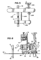
Figure 5 shows anapparatus 200 in accordance with the present invention for connecting and disconnecting tubulars TB and TL while a spinner apparatus 210 (shown schematically) in accordance with the present invention spins the tubular TB a wrench 202 (for example any suitable wrench or tong) holds the tubular TL. Ahanger 204 permits connection of thespinner apparatus 210 to another member or structure. Thewrench 202 is connected to thespinner apparatus 210 with a connection 206 and a spring 208. Thespinner apparatus 210 may include any spinner apparatus in accordance with the present invention, including but not limited to, that ofFigure 1A or ofFigure 7A . -
Figure 6 show anapparatus 10 in accordance with the present invention (like systems disclosed in co-ownedU.S. Patents 7,185,547 and7,062,991 ) which has acarriage 25 which is movably connected for up/down vertical movement to acolumn 14 and which can also translate horizontally on a rig floor RF for movement toward and away from a drill pipe D of a drill string DS in a wellW. Support arms 22, 24 (two each) are pivotably connected at one end to abase 23 of thecarriage 20. Optionally, only one support arm is used or two arms in parallel are used. Aconnector 21 is removably emplaceable in asocket 29 to mount the system on the rig. - A torque wrench 11 (for example as disclosed in co-owned
U.S. patents 7,185,547 and7,062,991 , or in any prior art cited therein) and a spinner apparatus 10 (any in accordance with the present invention) are connected to thecarriage 20 and are movable by a power mechanism PM toward and away from thecolumn 14 by moving thesupport arms spin wrench carriage 25 toward and away from the torque wrench. A control console CS for thespinner apparatus 10 is shown schematically inFigure 1B . Optionally, the console CS communicates by wire or wirelessly with the torque wrench 100 and/or thespinner apparatus 10 and/or the control console CS is located remotely from it. -
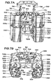
Figures 7A to 7H show aspinner apparatus 300 in accordance with the present invention which has aframe 312 with a crossmember 313 connecting two spaced-apartbeams 314 releasably connected byconnectors 316 to a hanging bracket 318. Clampingcylinder assemblies 320 disposed betweenframe members arms bogeys Cylinder yoke bushings 334 of theclamping cylinder assemblies 320 received and held in correspondingholes 326h, 328h inplates arms arms clamping cylinder assemblies 320. Acenter member 321 connected to both clampingcylinder assemblies 320 is secured to aframe center mount 335. It is within the scope of the present invention to use a single cylinder assembly instead of the twocylinder assemblies 320. - Each
arm bottom plate plates frame members pins 325. - Covers 341 - 344 shield motors 351 - 354 and rollers 361 - 364 which are rotated by the motors 351 - 354. The
bogeys - The
plates pin 339 moves. Thepin 339 extends through a hole 373 in anupper plate 332a and ahole 374 in alower plate 332b of thebogey 332. Theslots pin 339 thereby guiding movement of thebogey 332. This also guides the movement of therollers plate 332a provide structure to which thecover 343 is secured. Thecover 344 is secured to thearm 328. Thebogey 332 pivots about apin 348. Thepin 348 extends throughholes 388 in theplates 328a, 328b. - The
bogey 330 is "free floating"" in the sense that it is not slaved to anything and can pivot with respect to thearm 326 and can pivot, for example up to 10 degrees, with respect to the center line of the system. Thebogey 330 freely pivots about apin 345. Thebogey 330 has a top plate 330a and a bottom plate 330b. Thepin 345 passes throughholes bogey 330 to thearm 326. Thecover 341 is secured to mountblocks 375. Thecover 342 is secured to thearm 326. - The
motors bogey 332; and themotors bogey 330. Aflow divider 370 receives power fluid (for example hydraulic fluid under pressure from a rig source). Power fluid from theflow divider 370 is provided viaconnections 372 to the motors 351 - 354. Power fluid from theflow divider 370 is provided to theclamping cylinder assemblies 320 viaconnections 374. As shown the motors 351 - 354 are located above corresponding rollers; but it is within the scope of the present invention to locate the motors (or a single motor or two motors) at any convenient location whether above the rollers or not, below the rollers, or adjacent the rollers; or to use a single motor for driving multiple rollers, for example, but not limited to, a first motor for driving the rollers on one side, for example via appropriate gearing, and a second motor for driving the rollers on the other side. One motor can drive multiple rollers, for example via gearing, in synchronization. - The
roller 362 is mounted with portions in the holes likeholes 76a, 76b (seeFigure 2C ); theroller 361 is mounted with portions in the holes like 77a, 77b (seeFigure 2C ) ; theroller 364 is mounted with portions in the holes likeholes 78a, 78b (seeFigure 2B ); and theroller 63 is mounted with portions in theholes 79a, 79b. - A pin 347 extends through holes in the
plates plates arm 326 to theplates plates 328a, 328b and through holes in theplates arm 328 to theplates - The rollers 361 - 364 may be like any roller disclosed herein in accordance with the present invention (for example, but not limited to, the rollers shown in
Figures 1A and3C ). For example, theroller 363 has a plurality of spaced-apart projections 377 and a plurality of spaced-apart recesses 379. Any of the rollers 361 - 364 may have grooves like thegrooves Figures 3A - 3F . - As shown in
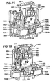
Figures 7E to 7H , the clamping cylinder apparatuses have been activated to move thearms bogeys pin 339 has guided the rotation of thebogey 332 about thepivot pin 348. The pin 337 prevents the bogey from trying to rotate in the opposite direction to therollers pin 339 slides along theslots 332a, 324a as the clamp cylinders are operated, but it is the end stroke of the clamp cylinders and not the slots that limit the extremes of clamping movement. Thebogey 332 can be considered as the "master" while thebogey 330 is the "slave". Thebogey 332 aligns the spinner unit precisely with the tubular centerline irrespective of the tubular diameter. Thebogey 330 then passively self aligns as clamp force is applied. - The rollers 361 - 364 are interlaced as shown in
Figures 7E - 7 H . Theroller 361 interlaces with theroller 362 and with theroller 363. Theroller 362 also interlaces with theroller 364. Theroller 364 interlaces with therollers - In certain aspects, interlacing of rollers works like treads on a tire; i.e. contact area is reduced and local contact pressure is increased, while surface contamination tends to be pressed into the grooves.
- Any suitable powered cylinder assemblies may be used for the
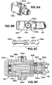
clamping cylinder assemblies 320. In one particular aspect, as shown inFigures 7H and8A to 8D , each clampingcylinder assembly 320 has ahousing 320a within which apiston 320p is movably mounted. To accommodate the pivoting of anarm 326 orarm 328 to which thehousing 320a is connected, apivotable connector 320c connects thepiston 320p to thecenter member 321. - The
connector 320c has afirst member 320d with a ball end 320e and asecond member 320f with aball end 320g. Apin 320h pins an end 320i of thesecond member 320f to thefirst member 320d. The ball end 320e of the first member is movable in a first spherical bearing 320j connected to thepiston 320p. Theball end 320g is movable in a secondspherical bearing 320k connected to thecenter member 321. Themembers piston 320p. Thus thehousing 320a is pivotable with respect to thehousing center member 321, allowing the cylinder to accommodate a certain amount of both angular and parallel misalignment without transferring significant loads to the cylinder slides and seals. Thus the fixed cylinders using thehemispherical bearings 320e, 320g are substantially or almost totally isolated from side loads (for example loads perpendicular to a longitudinal axis of themembers - A
seal 320m (for example, but not limited to, a rubber bellows apparatus) seals the housing-320a-center-mount-321 interface and prevents moisture and contamination from reaching the connector system and ball joints. A retainingring 321a screwed onto thecenter member 321 locks the ball end of the connector to thecenter member 321 to retain thespherical bearing 320k and resists cylinder retract loads when pressure is applied to the return side of the piston (pressure in thevolume space 320x). - Pressurized oil from the
flow divider 370 enters a cylinder retractport 320w to move the housing inwardly to unclamp the rollers from a tubular. The rollers are applied by supplying pressurized oil from theflow divider 370 to the rear of the piston via one of the two cylinder extendports 320r.Channels 320s within the body of the cylinder lead this oil to the rear of the piston. Oil within thespace 320x is pressed out of the cylinder retract port as the cylinder extends.
Claims (15)
- A spinner apparatus for facilitating connection and disconnection of threaded tubulars, the spinner apparatus comprising a first roller (61, 361) and a second roller (63,363) characterised in that the first roller has a projection (124) and the second roller has a recess (141), when in use, at least part of said projection (124) is located within at least part of said recess (141).
- A spinner apparatus as claimed in Claim 1, wherein the first and second rollers (61,361,63,363) are each generally cylindrical having a circular cross-section, the projection (124) projecting around the circumference thereof.
- A spinner apparatus as claimed in Claim 1 or 2, wherein the second roller (63,363) comprises at least two projections (124,129), the recess (141) formed therebetween.
- A spinner apparatus as claimed in Claim 3, wherein the first roller (61,361) comprises at least two recesses (141,143) and said at least one projection (129) formed between the at least two recesses (141,143).
- A spinner apparatus as claimed in Claims 3 and 4, wherein the at least two projections (128,129) of the first roller (61,361) interleave with the at least one projection (128,129) of the second roller (63,363).
- A spinner apparatus as claimed in any preceding claim, wherein the diameter of the first roller (61,361) is equal to the diameter of the second roller (63,363).
- A spinner apparatus as claimed in any preceding claim, wherein the first roller (61,361) comprises a plurality of projections and the second roller (63,363) comprises a plurality of projections (128,129), the plurality of projections (128,129) of said first roller (61,361) interleaving with the plurality of projections (128,129) of said second roller (63,363).
- A spinner apparatus as claimed in any preceding claim, wherein at least one of said first roller (61,361) and second roller (63,363) is arranged on a bogey (30,32).
- A spinner apparatus as claimed in Claim 8, wherein said bogey (32) is one of: a passive bogey; an active bogey.
- A spinner apparatus as claimed in Claim 8 or 9, wherein at least one of said bogey (30,32) comprises a further roller (62,362).
- A spinner apparatus as claimed in any of Claims 8 to 10, wherein at least one of said bogey (30,32) is pivotally arranged on an arm (28) movable on a piston and cylinder (20,320).
- A spinner apparatus as claimed in Claim 11, further comprising a further piston and cylinder (20,320), said further piston and cylinder linked to the piston and cylinder with a flexible union (321) preferably said arm (328) is linked to a body (12) and said free-floating union (321) movable in relation to said body (12) advantageously, said flexible union (321) comprises at least one of a ball (320g) and socket (320k) and said piston assembly comprises the other of the ball (320g) and socket (320k).
- A spinner apparatus as claimed in any preceding claim, wherein said first and second rollers (61,63,361,363) are driven by at least one motor.
- An apparatus for facilitating connection and disconnection of threaded tubulars, the apparatus comprising a spinning apparatus as claimed in any preceding claim and a torque apparatus for torquing a connection between the threaded tubulars.
- A method for facilitating connection and disconnection of threaded tubulars, the method comprising the steps of activating a spinner apparatus to move at least first and second rollers into contact with said tubular, said first roller comprising at least one projection and said second roller comprising at least one recess, said projection locating in at least part of said recess of the second roller and rotating at least one of said first and second rollers to spin at least one of said threaded tubulars.
Priority Applications (1)
| Application Number | Priority Date | Filing Date | Title |
|---|---|---|---|
| EP10179907A EP2287437A1 (en) | 2007-03-07 | 2008-02-29 | Spinner apparatus |
Applications Claiming Priority (3)
| Application Number | Priority Date | Filing Date | Title |
|---|---|---|---|
| US90547507P | 2007-03-07 | 2007-03-07 | |
| US12/072,296 US20090211404A1 (en) | 2008-02-25 | 2008-02-25 | Spinning wrench systems |
| PCT/GB2008/050143 WO2008107712A1 (en) | 2007-03-07 | 2008-02-29 | Spinner apparatus |
Related Child Applications (1)
| Application Number | Title | Priority Date | Filing Date |
|---|---|---|---|
| EP10179907.0 Division-Into | 2010-09-27 |
Publications (2)
| Publication Number | Publication Date |
|---|---|
| EP2118433A1 EP2118433A1 (en) | 2009-11-18 |
| EP2118433B1 true EP2118433B1 (en) | 2010-11-24 |
Family
ID=39427595
Family Applications (1)
| Application Number | Title | Priority Date | Filing Date |
|---|---|---|---|
| EP08709663A Active EP2118433B1 (en) | 2007-03-07 | 2008-02-29 | Spinner apparatus |
Country Status (8)
| Country | Link |
|---|---|
| EP (1) | EP2118433B1 (en) |
| AT (1) | ATE489532T1 (en) |
| BR (1) | BRPI0808327A8 (en) |
| CA (1) | CA2679698A1 (en) |
| DE (1) | DE602008003673D1 (en) |
| MX (1) | MX2009009471A (en) |
| RU (1) | RU2009137000A (en) |
| WO (1) | WO2008107712A1 (en) |
Families Citing this family (9)
| Publication number | Priority date | Publication date | Assignee | Title |
|---|---|---|---|---|
| US20090211404A1 (en) | 2008-02-25 | 2009-08-27 | Jan Erik Pedersen | Spinning wrench systems |
| FI121894B (en) * | 2009-02-12 | 2011-05-31 | Sandvik Mining & Constr Oy | Method of operating the holding device and holding device |
| US8752619B2 (en) | 2010-04-21 | 2014-06-17 | National Oilwell Varco, L.P. | Apparatus for suspending a downhole well string |
| US8944789B2 (en) | 2010-12-10 | 2015-02-03 | National Oilwell Varco, L.P. | Enhanced elastomeric stator insert via reinforcing agent distribution and orientation |
| US10538976B2 (en) | 2013-05-06 | 2020-01-21 | Drillform Technical Services Ltd. | Floor wrench for a drilling rig |
| TR201909719T4 (en) * | 2014-01-17 | 2019-07-22 | Drillform Technical Services Ltd | Rotation switch for drilling rig. |
| RU2678265C2 (en) | 2014-02-18 | 2019-01-24 | РЕМЕ ТЕКНОЛОДЖИС, ЭлЭлСи | Graphene enhanced elastomeric stator |
| US10648253B2 (en) | 2016-05-25 | 2020-05-12 | Cameron International Corporation | Modular spinner roller |
| US11608694B2 (en) | 2017-10-30 | 2023-03-21 | Drillform Technical Services Ltd. | Floor wrench for a drilling rig |
Family Cites Families (3)
| Publication number | Priority date | Publication date | Assignee | Title |
|---|---|---|---|---|
| US5660087A (en) * | 1995-08-08 | 1997-08-26 | Rae; Donald David | Drill pipe spinner |
| US7000502B2 (en) * | 2003-09-05 | 2006-02-21 | National-Ollwell | Drillpipe spinner |
| US7062991B1 (en) * | 2005-12-23 | 2006-06-20 | Varco I/P, Inc. | Tubular connect/disconnect apparatus |
-
2008
- 2008-02-29 WO PCT/GB2008/050143 patent/WO2008107712A1/en active Application Filing
- 2008-02-29 DE DE602008003673T patent/DE602008003673D1/en active Active
- 2008-02-29 RU RU2009137000/03A patent/RU2009137000A/en not_active Application Discontinuation
- 2008-02-29 AT AT08709663T patent/ATE489532T1/en not_active IP Right Cessation
- 2008-02-29 EP EP08709663A patent/EP2118433B1/en active Active
- 2008-02-29 BR BRPI0808327A patent/BRPI0808327A8/en not_active IP Right Cessation
- 2008-02-29 CA CA002679698A patent/CA2679698A1/en not_active Abandoned
- 2008-02-29 MX MX2009009471A patent/MX2009009471A/en not_active Application Discontinuation
Also Published As
| Publication number | Publication date |
|---|---|
| ATE489532T1 (en) | 2010-12-15 |
| CA2679698A1 (en) | 2008-09-12 |
| WO2008107712A1 (en) | 2008-09-12 |
| BRPI0808327A2 (en) | 2015-09-01 |
| EP2118433A1 (en) | 2009-11-18 |
| DE602008003673D1 (en) | 2011-01-05 |
| RU2009137000A (en) | 2011-04-20 |
| MX2009009471A (en) | 2009-10-28 |
| BRPI0808327A8 (en) | 2018-09-18 |
Similar Documents
| Publication | Publication Date | Title |
|---|---|---|
| EP2287437A1 (en) | Spinner apparatus | |
| EP2118433B1 (en) | Spinner apparatus | |
| US7707914B2 (en) | Apparatus and methods for connecting tubulars | |
| US3915244A (en) | Break out elevators for rotary drive assemblies | |
| CA2718014C (en) | Apparatus and method for facilitating connecting and disconnecting members | |
| CA2313078C (en) | Handling of tube sections in a rig for subsoil drilling | |
| CA2148346C (en) | Apparatus for gripping a down hole tubular | |
| US8109179B2 (en) | Power tong | |
| EP1559865A2 (en) | Wrenching unit | |
| US9988863B2 (en) | Apparatus and method for connecting components | |
| CN112338505B (en) | Pipe column connecting and disassembling device | |
| CA2298845C (en) | Drill rod loader | |
| WO2018004771A1 (en) | Pipe Wrench | |
| CN101646837A (en) | Spinner apparatus | |
| US20220090454A1 (en) | Slip apparatus and methods of using same | |
| CA2653877C (en) | Power tong | |
| US10364621B2 (en) | Pipe handling for a drill string at ground exit | |
| CA2714327C (en) | Method and apparatus for drilling with casing | |
| CN114585798A (en) | Torque tong with modular integrated spinner rollers and tong teeth | |
| CA2517993C (en) | Method and apparatus for drilling with casing |
Legal Events
| Date | Code | Title | Description |
|---|---|---|---|
| PUAI | Public reference made under article 153(3) epc to a published international application that has entered the european phase |
Free format text: ORIGINAL CODE: 0009012 |
|
| 17P | Request for examination filed |
Effective date: 20090907 |
|
| AK | Designated contracting states |
Kind code of ref document: A1 Designated state(s): AT BE BG CH CY CZ DE DK EE ES FI FR GB GR HR HU IE IS IT LI LT LU LV MC MT NL NO PL PT RO SE SI SK TR |
|
| GRAP | Despatch of communication of intention to grant a patent |
Free format text: ORIGINAL CODE: EPIDOSNIGR1 |
|
| DAX | Request for extension of the european patent (deleted) | ||
| RIN1 | Information on inventor provided before grant (corrected) |
Inventor name: BERGE, ROAR Inventor name: PEDERSEN, JAN, ERIK Inventor name: WEBB, JONATHAN, GARRICK |
|
| GRAS | Grant fee paid |
Free format text: ORIGINAL CODE: EPIDOSNIGR3 |
|
| GRAA | (expected) grant |
Free format text: ORIGINAL CODE: 0009210 |
|
| AK | Designated contracting states |
Kind code of ref document: B1 Designated state(s): AT BE BG CH CY CZ DE DK EE ES FI FR GB GR HR HU IE IS IT LI LT LU LV MC MT NL NO PL PT RO SE SI SK TR |
|
| REG | Reference to a national code |
Ref country code: GB Ref legal event code: FG4D |
|
| REG | Reference to a national code |
Ref country code: CH Ref legal event code: EP |
|
| REG | Reference to a national code |
Ref country code: IE Ref legal event code: FG4D |
|
| REF | Corresponds to: |
Ref document number: 602008003673 Country of ref document: DE Date of ref document: 20110105 Kind code of ref document: P |
|
| REG | Reference to a national code |
Ref country code: NL Ref legal event code: T3 |
|
| REG | Reference to a national code |
Ref country code: NO Ref legal event code: T2 Effective date: 20101124 |
|
| LTIE | Lt: invalidation of european patent or patent extension |
Effective date: 20101124 |
|
| PG25 | Lapsed in a contracting state [announced via postgrant information from national office to epo] |
Ref country code: LT Free format text: LAPSE BECAUSE OF FAILURE TO SUBMIT A TRANSLATION OF THE DESCRIPTION OR TO PAY THE FEE WITHIN THE PRESCRIBED TIME-LIMIT Effective date: 20101124 |
|
| PGFP | Annual fee paid to national office [announced via postgrant information from national office to epo] |
Ref country code: NO Payment date: 20110225 Year of fee payment: 4 |
|
| PG25 | Lapsed in a contracting state [announced via postgrant information from national office to epo] |
Ref country code: FI Free format text: LAPSE BECAUSE OF FAILURE TO SUBMIT A TRANSLATION OF THE DESCRIPTION OR TO PAY THE FEE WITHIN THE PRESCRIBED TIME-LIMIT Effective date: 20101124 Ref country code: CY Free format text: LAPSE BECAUSE OF FAILURE TO SUBMIT A TRANSLATION OF THE DESCRIPTION OR TO PAY THE FEE WITHIN THE PRESCRIBED TIME-LIMIT Effective date: 20101124 Ref country code: SE Free format text: LAPSE BECAUSE OF FAILURE TO SUBMIT A TRANSLATION OF THE DESCRIPTION OR TO PAY THE FEE WITHIN THE PRESCRIBED TIME-LIMIT Effective date: 20101124 Ref country code: HR Free format text: LAPSE BECAUSE OF FAILURE TO SUBMIT A TRANSLATION OF THE DESCRIPTION OR TO PAY THE FEE WITHIN THE PRESCRIBED TIME-LIMIT Effective date: 20101124 Ref country code: LV Free format text: LAPSE BECAUSE OF FAILURE TO SUBMIT A TRANSLATION OF THE DESCRIPTION OR TO PAY THE FEE WITHIN THE PRESCRIBED TIME-LIMIT Effective date: 20101124 Ref country code: BG Free format text: LAPSE BECAUSE OF FAILURE TO SUBMIT A TRANSLATION OF THE DESCRIPTION OR TO PAY THE FEE WITHIN THE PRESCRIBED TIME-LIMIT Effective date: 20110224 Ref country code: PT Free format text: LAPSE BECAUSE OF FAILURE TO SUBMIT A TRANSLATION OF THE DESCRIPTION OR TO PAY THE FEE WITHIN THE PRESCRIBED TIME-LIMIT Effective date: 20110324 Ref country code: IS Free format text: LAPSE BECAUSE OF FAILURE TO SUBMIT A TRANSLATION OF THE DESCRIPTION OR TO PAY THE FEE WITHIN THE PRESCRIBED TIME-LIMIT Effective date: 20110324 Ref country code: AT Free format text: LAPSE BECAUSE OF FAILURE TO SUBMIT A TRANSLATION OF THE DESCRIPTION OR TO PAY THE FEE WITHIN THE PRESCRIBED TIME-LIMIT Effective date: 20101124 Ref country code: SI Free format text: LAPSE BECAUSE OF FAILURE TO SUBMIT A TRANSLATION OF THE DESCRIPTION OR TO PAY THE FEE WITHIN THE PRESCRIBED TIME-LIMIT Effective date: 20101124 |
|
| PG25 | Lapsed in a contracting state [announced via postgrant information from national office to epo] |
Ref country code: GR Free format text: LAPSE BECAUSE OF FAILURE TO SUBMIT A TRANSLATION OF THE DESCRIPTION OR TO PAY THE FEE WITHIN THE PRESCRIBED TIME-LIMIT Effective date: 20110225 |
|
| PG25 | Lapsed in a contracting state [announced via postgrant information from national office to epo] |
Ref country code: EE Free format text: LAPSE BECAUSE OF FAILURE TO SUBMIT A TRANSLATION OF THE DESCRIPTION OR TO PAY THE FEE WITHIN THE PRESCRIBED TIME-LIMIT Effective date: 20101124 Ref country code: ES Free format text: LAPSE BECAUSE OF FAILURE TO SUBMIT A TRANSLATION OF THE DESCRIPTION OR TO PAY THE FEE WITHIN THE PRESCRIBED TIME-LIMIT Effective date: 20110307 Ref country code: BE Free format text: LAPSE BECAUSE OF FAILURE TO SUBMIT A TRANSLATION OF THE DESCRIPTION OR TO PAY THE FEE WITHIN THE PRESCRIBED TIME-LIMIT Effective date: 20101124 Ref country code: CZ Free format text: LAPSE BECAUSE OF FAILURE TO SUBMIT A TRANSLATION OF THE DESCRIPTION OR TO PAY THE FEE WITHIN THE PRESCRIBED TIME-LIMIT Effective date: 20101124 |
|
| PG25 | Lapsed in a contracting state [announced via postgrant information from national office to epo] |
Ref country code: SK Free format text: LAPSE BECAUSE OF FAILURE TO SUBMIT A TRANSLATION OF THE DESCRIPTION OR TO PAY THE FEE WITHIN THE PRESCRIBED TIME-LIMIT Effective date: 20101124 Ref country code: RO Free format text: LAPSE BECAUSE OF FAILURE TO SUBMIT A TRANSLATION OF THE DESCRIPTION OR TO PAY THE FEE WITHIN THE PRESCRIBED TIME-LIMIT Effective date: 20101124 Ref country code: PL Free format text: LAPSE BECAUSE OF FAILURE TO SUBMIT A TRANSLATION OF THE DESCRIPTION OR TO PAY THE FEE WITHIN THE PRESCRIBED TIME-LIMIT Effective date: 20101124 Ref country code: DK Free format text: LAPSE BECAUSE OF FAILURE TO SUBMIT A TRANSLATION OF THE DESCRIPTION OR TO PAY THE FEE WITHIN THE PRESCRIBED TIME-LIMIT Effective date: 20101124 |
|
| PLBE | No opposition filed within time limit |
Free format text: ORIGINAL CODE: 0009261 |
|
| STAA | Information on the status of an ep patent application or granted ep patent |
Free format text: STATUS: NO OPPOSITION FILED WITHIN TIME LIMIT |
|
| PG25 | Lapsed in a contracting state [announced via postgrant information from national office to epo] |
Ref country code: MC Free format text: LAPSE BECAUSE OF NON-PAYMENT OF DUE FEES Effective date: 20110331 |
|
| 26N | No opposition filed |
Effective date: 20110825 |
|
| REG | Reference to a national code |
Ref country code: FR Ref legal event code: ST Effective date: 20111102 |
|
| REG | Reference to a national code |
Ref country code: IE Ref legal event code: MM4A |
|
| REG | Reference to a national code |
Ref country code: DE Ref legal event code: R097 Ref document number: 602008003673 Country of ref document: DE Effective date: 20110825 |
|
| PG25 | Lapsed in a contracting state [announced via postgrant information from national office to epo] |
Ref country code: MT Free format text: LAPSE BECAUSE OF FAILURE TO SUBMIT A TRANSLATION OF THE DESCRIPTION OR TO PAY THE FEE WITHIN THE PRESCRIBED TIME-LIMIT Effective date: 20101124 Ref country code: IT Free format text: LAPSE BECAUSE OF FAILURE TO SUBMIT A TRANSLATION OF THE DESCRIPTION OR TO PAY THE FEE WITHIN THE PRESCRIBED TIME-LIMIT Effective date: 20101124 |
|
| REG | Reference to a national code |
Ref country code: DE Ref legal event code: R119 Ref document number: 602008003673 Country of ref document: DE Effective date: 20110901 |
|
| PG25 | Lapsed in a contracting state [announced via postgrant information from national office to epo] |
Ref country code: IE Free format text: LAPSE BECAUSE OF NON-PAYMENT OF DUE FEES Effective date: 20110228 Ref country code: FR Free format text: LAPSE BECAUSE OF NON-PAYMENT OF DUE FEES Effective date: 20110228 |
|
| REG | Reference to a national code |
Ref country code: CH Ref legal event code: PL |
|
| PG25 | Lapsed in a contracting state [announced via postgrant information from national office to epo] |
Ref country code: CH Free format text: LAPSE BECAUSE OF NON-PAYMENT OF DUE FEES Effective date: 20120229 Ref country code: NO Free format text: LAPSE BECAUSE OF NON-PAYMENT OF DUE FEES Effective date: 20120229 Ref country code: LI Free format text: LAPSE BECAUSE OF NON-PAYMENT OF DUE FEES Effective date: 20120229 |
|
| PG25 | Lapsed in a contracting state [announced via postgrant information from national office to epo] |
Ref country code: LU Free format text: LAPSE BECAUSE OF NON-PAYMENT OF DUE FEES Effective date: 20110228 |
|
| PG25 | Lapsed in a contracting state [announced via postgrant information from national office to epo] |
Ref country code: DE Free format text: LAPSE BECAUSE OF NON-PAYMENT OF DUE FEES Effective date: 20110901 |
|
| PG25 | Lapsed in a contracting state [announced via postgrant information from national office to epo] |
Ref country code: TR Free format text: LAPSE BECAUSE OF FAILURE TO SUBMIT A TRANSLATION OF THE DESCRIPTION OR TO PAY THE FEE WITHIN THE PRESCRIBED TIME-LIMIT Effective date: 20101124 |
|
| PG25 | Lapsed in a contracting state [announced via postgrant information from national office to epo] |
Ref country code: HU Free format text: LAPSE BECAUSE OF FAILURE TO SUBMIT A TRANSLATION OF THE DESCRIPTION OR TO PAY THE FEE WITHIN THE PRESCRIBED TIME-LIMIT Effective date: 20101124 |
|
| PGFP | Annual fee paid to national office [announced via postgrant information from national office to epo] |
Ref country code: GB Payment date: 20230105 Year of fee payment: 16 |
|
| PGFP | Annual fee paid to national office [announced via postgrant information from national office to epo] |
Ref country code: NL Payment date: 20230113 Year of fee payment: 16 |
|
| PGFP | Annual fee paid to national office [announced via postgrant information from national office to epo] |
Ref country code: NL Payment date: 20240108 Year of fee payment: 17 |