EP2117845B1 - Screen printing machine and method - Google Patents
Screen printing machine and method Download PDFInfo
- Publication number
- EP2117845B1 EP2117845B1 EP08734584A EP08734584A EP2117845B1 EP 2117845 B1 EP2117845 B1 EP 2117845B1 EP 08734584 A EP08734584 A EP 08734584A EP 08734584 A EP08734584 A EP 08734584A EP 2117845 B1 EP2117845 B1 EP 2117845B1
- Authority
- EP
- European Patent Office
- Prior art keywords
- workpiece
- screen
- printing machine
- end effector
- vision camera
- Prior art date
- Legal status (The legal status is an assumption and is not a legal conclusion. Google has not performed a legal analysis and makes no representation as to the accuracy of the status listed.)
- Active
Links
Images



Classifications
-
- B—PERFORMING OPERATIONS; TRANSPORTING
- B41—PRINTING; LINING MACHINES; TYPEWRITERS; STAMPS
- B41F—PRINTING MACHINES OR PRESSES
- B41F15/00—Screen printers
- B41F15/08—Machines
- B41F15/12—Machines with auxiliary equipment, e.g. for drying printed articles
-
- B—PERFORMING OPERATIONS; TRANSPORTING
- B41—PRINTING; LINING MACHINES; TYPEWRITERS; STAMPS
- B41F—PRINTING MACHINES OR PRESSES
- B41F15/00—Screen printers
- B41F15/14—Details
- B41F15/40—Inking units
-
- B—PERFORMING OPERATIONS; TRANSPORTING
- B41—PRINTING; LINING MACHINES; TYPEWRITERS; STAMPS
- B41F—PRINTING MACHINES OR PRESSES
- B41F15/00—Screen printers
- B41F15/14—Details
-
- B—PERFORMING OPERATIONS; TRANSPORTING
- B41—PRINTING; LINING MACHINES; TYPEWRITERS; STAMPS
- B41M—PRINTING, DUPLICATING, MARKING, OR COPYING PROCESSES; COLOUR PRINTING
- B41M1/00—Inking and printing with a printer's forme
- B41M1/12—Stencil printing; Silk-screen printing
- B41M1/125—Stencil printing; Silk-screen printing using a field of force, e.g. an electrostatic field, or an electric current
-
- H—ELECTRICITY
- H05—ELECTRIC TECHNIQUES NOT OTHERWISE PROVIDED FOR
- H05K—PRINTED CIRCUITS; CASINGS OR CONSTRUCTIONAL DETAILS OF ELECTRIC APPARATUS; MANUFACTURE OF ASSEMBLAGES OF ELECTRICAL COMPONENTS
- H05K3/00—Apparatus or processes for manufacturing printed circuits
- H05K3/0008—Apparatus or processes for manufacturing printed circuits for aligning or positioning of tools relative to the circuit board
-
- H—ELECTRICITY
- H05—ELECTRIC TECHNIQUES NOT OTHERWISE PROVIDED FOR
- H05K—PRINTED CIRCUITS; CASINGS OR CONSTRUCTIONAL DETAILS OF ELECTRIC APPARATUS; MANUFACTURE OF ASSEMBLAGES OF ELECTRICAL COMPONENTS
- H05K3/00—Apparatus or processes for manufacturing printed circuits
- H05K3/10—Apparatus or processes for manufacturing printed circuits in which conductive material is applied to the insulating support in such a manner as to form the desired conductive pattern
- H05K3/12—Apparatus or processes for manufacturing printed circuits in which conductive material is applied to the insulating support in such a manner as to form the desired conductive pattern using thick film techniques, e.g. printing techniques to apply the conductive material or similar techniques for applying conductive paste or ink patterns
- H05K3/1216—Apparatus or processes for manufacturing printed circuits in which conductive material is applied to the insulating support in such a manner as to form the desired conductive pattern using thick film techniques, e.g. printing techniques to apply the conductive material or similar techniques for applying conductive paste or ink patterns by screen printing or stencil printing
-
- H—ELECTRICITY
- H05—ELECTRIC TECHNIQUES NOT OTHERWISE PROVIDED FOR
- H05K—PRINTED CIRCUITS; CASINGS OR CONSTRUCTIONAL DETAILS OF ELECTRIC APPARATUS; MANUFACTURE OF ASSEMBLAGES OF ELECTRICAL COMPONENTS
- H05K3/00—Apparatus or processes for manufacturing printed circuits
- H05K3/10—Apparatus or processes for manufacturing printed circuits in which conductive material is applied to the insulating support in such a manner as to form the desired conductive pattern
- H05K3/12—Apparatus or processes for manufacturing printed circuits in which conductive material is applied to the insulating support in such a manner as to form the desired conductive pattern using thick film techniques, e.g. printing techniques to apply the conductive material or similar techniques for applying conductive paste or ink patterns
- H05K3/1216—Apparatus or processes for manufacturing printed circuits in which conductive material is applied to the insulating support in such a manner as to form the desired conductive pattern using thick film techniques, e.g. printing techniques to apply the conductive material or similar techniques for applying conductive paste or ink patterns by screen printing or stencil printing
- H05K3/1233—Methods or means for supplying the conductive material and for forcing it through the screen or stencil
-
- H—ELECTRICITY
- H05—ELECTRIC TECHNIQUES NOT OTHERWISE PROVIDED FOR
- H05K—PRINTED CIRCUITS; CASINGS OR CONSTRUCTIONAL DETAILS OF ELECTRIC APPARATUS; MANUFACTURE OF ASSEMBLAGES OF ELECTRICAL COMPONENTS
- H05K1/00—Printed circuits
- H05K1/02—Details
- H05K1/0266—Marks, test patterns or identification means
- H05K1/0269—Marks, test patterns or identification means for visual or optical inspection
-
- H—ELECTRICITY
- H05—ELECTRIC TECHNIQUES NOT OTHERWISE PROVIDED FOR
- H05K—PRINTED CIRCUITS; CASINGS OR CONSTRUCTIONAL DETAILS OF ELECTRIC APPARATUS; MANUFACTURE OF ASSEMBLAGES OF ELECTRICAL COMPONENTS
- H05K2203/00—Indexing scheme relating to apparatus or processes for manufacturing printed circuits covered by H05K3/00
- H05K2203/01—Tools for processing; Objects used during processing
- H05K2203/0104—Tools for processing; Objects used during processing for patterning or coating
- H05K2203/0126—Dispenser, e.g. for solder paste, for supplying conductive paste for screen printing or for filling holes
-
- H—ELECTRICITY
- H05—ELECTRIC TECHNIQUES NOT OTHERWISE PROVIDED FOR
- H05K—PRINTED CIRCUITS; CASINGS OR CONSTRUCTIONAL DETAILS OF ELECTRIC APPARATUS; MANUFACTURE OF ASSEMBLAGES OF ELECTRICAL COMPONENTS
- H05K2203/00—Indexing scheme relating to apparatus or processes for manufacturing printed circuits covered by H05K3/00
- H05K2203/01—Tools for processing; Objects used during processing
- H05K2203/0104—Tools for processing; Objects used during processing for patterning or coating
- H05K2203/013—Inkjet printing, e.g. for printing insulating material or resist
-
- H—ELECTRICITY
- H05—ELECTRIC TECHNIQUES NOT OTHERWISE PROVIDED FOR
- H05K—PRINTED CIRCUITS; CASINGS OR CONSTRUCTIONAL DETAILS OF ELECTRIC APPARATUS; MANUFACTURE OF ASSEMBLAGES OF ELECTRICAL COMPONENTS
- H05K2203/00—Indexing scheme relating to apparatus or processes for manufacturing printed circuits covered by H05K3/00
- H05K2203/01—Tools for processing; Objects used during processing
- H05K2203/0195—Tool for a process not provided for in H05K3/00, e.g. tool for handling objects using suction, for deforming objects, for applying local pressure
-
- H—ELECTRICITY
- H05—ELECTRIC TECHNIQUES NOT OTHERWISE PROVIDED FOR
- H05K—PRINTED CIRCUITS; CASINGS OR CONSTRUCTIONAL DETAILS OF ELECTRIC APPARATUS; MANUFACTURE OF ASSEMBLAGES OF ELECTRICAL COMPONENTS
- H05K2203/00—Indexing scheme relating to apparatus or processes for manufacturing printed circuits covered by H05K3/00
- H05K2203/10—Using electric, magnetic and electromagnetic fields; Using laser light
- H05K2203/107—Using laser light
-
- H—ELECTRICITY
- H05—ELECTRIC TECHNIQUES NOT OTHERWISE PROVIDED FOR
- H05K—PRINTED CIRCUITS; CASINGS OR CONSTRUCTIONAL DETAILS OF ELECTRIC APPARATUS; MANUFACTURE OF ASSEMBLAGES OF ELECTRICAL COMPONENTS
- H05K3/00—Apparatus or processes for manufacturing printed circuits
- H05K3/10—Apparatus or processes for manufacturing printed circuits in which conductive material is applied to the insulating support in such a manner as to form the desired conductive pattern
- H05K3/12—Apparatus or processes for manufacturing printed circuits in which conductive material is applied to the insulating support in such a manner as to form the desired conductive pattern using thick film techniques, e.g. printing techniques to apply the conductive material or similar techniques for applying conductive paste or ink patterns
- H05K3/1241—Apparatus or processes for manufacturing printed circuits in which conductive material is applied to the insulating support in such a manner as to form the desired conductive pattern using thick film techniques, e.g. printing techniques to apply the conductive material or similar techniques for applying conductive paste or ink patterns by ink-jet printing or drawing by dispensing
- H05K3/125—Apparatus or processes for manufacturing printed circuits in which conductive material is applied to the insulating support in such a manner as to form the desired conductive pattern using thick film techniques, e.g. printing techniques to apply the conductive material or similar techniques for applying conductive paste or ink patterns by ink-jet printing or drawing by dispensing by ink-jet printing
-
- H—ELECTRICITY
- H05—ELECTRIC TECHNIQUES NOT OTHERWISE PROVIDED FOR
- H05K—PRINTED CIRCUITS; CASINGS OR CONSTRUCTIONAL DETAILS OF ELECTRIC APPARATUS; MANUFACTURE OF ASSEMBLAGES OF ELECTRICAL COMPONENTS
- H05K3/00—Apparatus or processes for manufacturing printed circuits
- H05K3/30—Assembling printed circuits with electric components, e.g. with resistors
- H05K3/32—Assembling printed circuits with electric components, e.g. with resistors electrically connecting electric components or wires to printed circuits
- H05K3/34—Assembling printed circuits with electric components, e.g. with resistors electrically connecting electric components or wires to printed circuits by soldering
- H05K3/3465—Application of solder
- H05K3/3485—Application of solder paste, slurry or powder
Definitions
- the present invention relates to a screen printing machine, in particular a surface mount technology (SMT) screen printing machine, which provides for additional functionality, in incorporating an additional end effector, such as a material-dispensing effector for enabling the dispensing of deposits of a material onto a workpiece in addition to the conventional printing operation, and a method of operating such a screen printing machine.
- SMT surface mount technology
- an SMT assembly line includes a plurality of dedicated machines, which separately perform operations on a workpiece, typically a printed circuit board, as required in an SMT process, including a screen printing machine for performing a screen printing operation to print workpieces through a printing screen with a pattern of material deposits, such as of solder paste or adhesive, and a dispensing machine for dispensing material deposits, again such as of solder paste or adhesive, directly onto a workpiece.
- a screen printing machine for performing a screen printing operation to print workpieces through a printing screen with a pattern of material deposits, such as of solder paste or adhesive
- a dispensing machine for dispensing material deposits, again such as of solder paste or adhesive, directly onto a workpiece.
- a conventional screen printing machine is disclosed in GB-A-2 344 312 .
- Such screen printing machines are supplied, for example, by DEK INTERNATIONAL GMBH (Zürich, Switzerland), EKRA AUTOMATISIERUNGSSYSTEME GMBH (Bönningheim, Germany) and SPEEDLINE TECHNOLOGIES, INC. (Franklin, MA, USA).
- a screen printing machine can be configured to provide a further operation, in particular a material-dispensing operation, through the provision of an end effector in conjunction with the vision camera, which, as part of the alignment mechanism, is moved over the surface of a workpiece as supported in the screen printing machine and referenced thereto, such as to allow the end effector to be positioned by reference to the vision camera.
- This use of a screen printing machine advantageously allows for the extended use of a screen printing machine, and also avoids the need for a dedicated piece of equipment to perform an operation which may be required infrequently. Such equipment is both expensive and requires the allocation of floorspace, which may be better utilized.
- the present invention provides a screen printing machine, comprising: a print head which is operable to drive a material through a printing screen and deposit the material onto a workpiece; an imaging unit which comprises a vision camera for imaging at least one of the printing screen and the workpiece, and a positioning mechanism which is operable to position the vision camera; and an end effector which is operable to perform an operation on the workpiece and is coupled to the vision camera, such as to be moved commonly therewith by the positioning mechanism; wherein the screen printing machine is operable in one of a first mode in which the print head is operated to print material deposits on the workpiece, and a second mode in which the end effector is actuated to perform an operation on the workpiece at defined positions.
- the screen printing machine is operable in one of a first mode in which only the print head is operated to print material deposits on the workpiece, a second mode in which, preferably successively, the print head is operated to print material deposits on the workpiece and the end effector is actuated to perform an operation on the workpiece at defined positions, and a third mode in which only the end effector is actuated to perform an operation on the workpiece at defined positions.
- the positioning mechanism is operable to position the vision camera between the printing screen and the workpiece.
- the screen printing machine further comprises: a frame support for supporting a printing screen unit which includes a printing screen having a pattern of apertures therein.
- the screen printing machine further comprises: an alignment unit for aligning the printing screen unit relative to the workpiece in response to features imaged on at least one of the printing screen and the workpiece.
- the screen printing machine further comprises: a workpiece support for supporting the workpiece.
- the positioning mechanism is operable to position the vision camera in an X-Y plane.
- the positioning mechanism comprises an X-Y gantry.
- the positioning mechanism comprises first and second positioning units, which provide for positioning of the vision camera in respective ones of orthogonal, X-Y axes, such as to be operable together to provide for positioning of the vision camera in the X-Y plane.
- first positioning unit comprises first and second positioners, which are mounted in parallel relation, and a bridge member, which interconnects the first and second positioners, and is moved by common operation of the first and second positioners to position the vision camera in one axis.
- the first positioning unit comprises at least one actuator for actuating the first and second positioners thereof.
- the at least one actuator comprises one of a stepping motor or a servo motor.
- the first positioning unit comprises a single actuator for actuating the first and second positioners thereof.
- the other, second positioning unit comprises a positioner, which is mounted to the bridge member of the first positioning unit in orthogonal relation to the first and second positioners thereof, and is operable to position the vision camera in the other, orthogonal axis.
- the second positioning unit comprises an actuator for actuating the positioner thereof.
- the actuator comprises one of a stepping motor or a servo motor.
- the end effector is a material-dispensing effector for dispensing material deposits onto the workpiece in a desired pattern.
- the material-dispensing effector is controlled to dispense material deposits in dependence upon the movement thereof.
- the materials as deposited by the print head and the end effector are different.
- the materials as deposited by the print head and the end effector are the same.
- the materials are selected from a solder paste, a solder flux and an adhesive.
- the end effector is an ink-jetting effector for delivering a liquid to the workpiece in a desired pattern.
- the end effector is a component-mounting effector for mounting components at defined locations on the workpiece.
- the end effector is a laser-etching effector for laser etching a desired pattern in the workpiece.
- the present invention provides a screen printing machine, comprising: a print head which is operable to drive a material through a printing screen and deposit the material onto a workpiece; an imaging unit which comprises a vision camera for imaging at least one of the printing screen and the workpiece and a positioning mechanism which is operable to position the vision camera; and an end effector which is operable to perform an operation on the workpiece and is coupled to the vision camera, such as to be moved commonly therewith by the positioning mechanism; wherein the screen printing machine is operable in one of a first mode in which the print head is operated to print material deposits on the workpiece, and a second mode in which the print head is operated to print material deposits on the workpiece and the end effector is actuated to perform an operation on the workpiece at defined positions.
- the present invention provides a method of operating a screen printing machine, which comprises a print head which is operable to drive a material through a printing screen and deposit the material onto a workpiece, an imaging unit which comprises a vision camera for imaging at least one of the printing screen and the workpiece and a positioning mechanism which is operable to position the vision camera, and an end effector which is operable to perform an operation on the workpiece and is coupled to the vision camera, such as to be moved commonly therewith, the method comprising the step of: operating the screen printing machine in one of a first mode in which the print head is driven to print material deposits on a workpiece, and a second mode in which the end effector is actuated to perform an operation on the workpiece at defined positions.
- the screen printing machine operating step comprises the step of: operating the screen printing machine in one of a first mode in which only the print head is driven to print material deposits on a workpiece, a second mode in which, preferably successively, the print head is driven to print material deposits on a workpiece and the end effector is actuated to perform an operation on the workpiece at defined positions, and a third mode in which only the end effector is actuated to perform an operation on a workpiece at defined positions.
- the positioning mechanism is operable to position the vision camera between the printing screen and the workpiece.
- the method further comprises the steps of: operating the imaging unit to move the vision camera and image features on at least one of the printing screen and the workpiece; and aligning the printing screen relative to the workpiece in response to the imaged features.
- the end effector is a material-dispensing effector for dispensing material deposits onto the workpiece in a desired pattern.
- the material-dispensing effector is controlled to dispense material deposits in dependence upon the movement thereof.
- the materials as deposited by the print head and the end effector are different.
- the materials as deposited by the print head and the end effector are the same.
- the materials are selected from a solder paste, a solder flux and an adhesive.
- the end effector is an ink-jetting effector which is actuated to deliver a liquid to the workpiece in a desired pattern.
- the end effector is a component-mounting effector which is actuated to mount components at defined locations on the workpiece.
- the end effector is a laser-etching effector which is actuated to laser etch a desired pattern in the workpiece.
- the workpiece is a printed circuit board.
- the present invention provides a method of operating a screen printing machine, which comprises a print head which is operable to drive a material through a printing screen and deposit the material onto a workpiece, an imaging unit which comprises a vision camera for imaging at least one of the printing screen and the workpiece and a positioning mechanism which is operable to position the vision camera, and an end effector which is operable to perform an operation on the workpiece and is coupled to the vision camera, such as to be moved commonly therewith, the method comprising the step of: operating the screen printing machine in one of a first mode in which the print head is driven to print material deposits on a workpiece, and a second mode in which the print head is driven to print material deposits on a workpiece and the end effector is actuated to perform an operation on the workpiece at defined positions.
- the screen printing machine comprises a frame support 103 which supports a printing screen unit 105, which comprises a mounting frame 107 and a printing screen 109 which is mounted thereto, and a print head 111 which is movable back and forth across the printing screen 109 to drive a material, such as a solder paste or an adhesive, through a pattern of apertures in the printing screen 109, and deposit the material onto a workpiece W disposed therebeneath.
- a material such as a solder paste or an adhesive
- the screen printing machine further comprises a workpiece support 115 which is disposed beneath the printing screen 109 to support a workpiece W at an operating zone, and a workpiece transport mechanism 117 which includes a pair of transport rails 119, 120 along which workpieces W are transported to and from the workpiece support 115.
- the screen printing machine further comprises an imaging unit 121 for capturing images of fiducials on the printing screen 109 and the workpiece W.
- the imaging unit 121 comprises a vision camera 123 and a positioning mechanism 125 which is operative to position the vision camera 123 in an X-Y plane between the printing screen 109 and the workpiece W, such that the vision camera 123 captures images of the printing screen 109 and the workpiece W and detects the fiducials thereon.
- the positioning mechanism 125 is configured to move the vision camera 123 through a pre-defined path in the X-Y plane in order to capture a sequence of images which includes all of the fiducials.
- the positioning mechanism 125 comprises an X-Y gantry which includes first and second positioning units 126, 127, which provide for positioning of the vision camera 123 in respective ones of orthogonal, X-Y axes, such as to be operable together to provide for positioning of the vision camera 123 in the X-Y plane.
- the first positioning unit 126 here a Y-axis positioning unit, comprises first and second Y-axis positioners 129, 131, a bridge member 133, which interconnects the first and second Y-axis positioners 129, 131 and is moved by common operation of the same, and at least one, in this embodiment a single actuator 134 for actuating the Y-axis positioners 129, 131, such as to position the vision camera 123 in the Y-axis.
- the at least one actuator 134 comprises one of a stepping motor or a servo motor, and includes an encoder which allows for highly-accurate positioning of the vision camera 123.
- the second positioning unit 127 here an X-axis positioning unit, comprises an X-axis positioner 135, which is mounted to the bridge member 133 of the Y-axis positioning unit 126 In orthogonal relation to the Y-axis positioners 129, 131, and an actuator 136 for actuating the X-axis positioner 135, such as to position the vision camera 123 in the X-axis.
- the screen printing machine further comprises an alignment unit 137, in this embodiment an X-X-Y table, for X, Y and ⁇ alignment of the printing screen unit 105 relative to the workpiece support 115 in response to the imaged fiducials.
- an alignment unit 137 in this embodiment an X-X-Y table, for X, Y and ⁇ alignment of the printing screen unit 105 relative to the workpiece support 115 in response to the imaged fiducials.
- the imaging unit 121 further comprises an end effector 141 which is coupled to the vision camera 123, such as to be moved commonly therewith.
- the end effector 141 has a fixed, offset position relative to the datum of the vision camera 123, which allows for positioning of the end effector 141 in the X-Y plane relative to the workpiece W as required for operation of the end effector 141 on the workpiece W, as will be described in more detail hereinbelow.
- the end effector 141 is a material-dispensing effector for dispensing deposits of a material, typically a viscous material or liquid, such as an adhesive, a solder flux or a solder paste, from a reservoir onto a workpiece W in a desired pattern, with the fluid-dispensing effector being controlled to dispense material deposits in dependence on the movement thereof.
- a material typically a viscous material or liquid, such as an adhesive, a solder flux or a solder paste
- the end effector 141 could be any other kind of effector for operating in relation to a workpiece W, including but not limited to an ink-jetting effector for delivering a liquid to a workpiece W in a desired pattern, a component-mounting effector for mounting components at defined locations on a workpiece W and a laser-etching effector for laser etching a desired pattern in a workpiece W.
- an ink-jetting effector for delivering a liquid to a workpiece W in a desired pattern
- a component-mounting effector for mounting components at defined locations on a workpiece W
- a laser-etching effector for laser etching a desired pattern in a workpiece W.
- the screen printing machine further comprises a controller 145 for controlling operation of the screen printing machine.
- a workpiece W such as a printed circuit board, is transported by the workpiece transport mechanism 117 to a location above the workpiece support 115.
- workpieces W are automatically transported in succession in accordance with the normal control routine of the screen printing machine.
- Step S2 the workpiece support 115 is actuated to support the workpiece W as located thereabove by the workpiece transport mechanism 117.
- the workpiece support 115 is operated automatically in accordance with the normal control routine of the screen printing machine.
- Step S3 the imaging unit 121 is operated to capture fiducials both on the printing screen 109 and the workpiece W, in this embodiment by operating the positioning mechanism 125 to move the vision camera 123 through the X-Y plane between the printing screen 109 and the workpiece W.
- the imaging unit 121 is operated automatically in accordance with the normal control routine of the screen printing machine.
- a fourth step the alignment unit 137 is operated to align the printing screen 109 relative to the workpiece W, such as to establish common X-Y axes and a 0, 0 datum.
- the alignment unit 137 is operated automatically in accordance with the normal control routine of the screen printing machine.
- the printing screen unit 105 is moved in relation to the workpiece support 115, such as to align the printing screen 109 relative to the workpiece W.
- the workpiece support 115 could be moved in relation to the printing screen unit 105, such as to align the printing screen 109 relative to the workpiece W.
- a fifth step the workpiece support 115 is operated such as to bring the supported workpiece W into a position adjacent the underside of the printing screen 109.
- the workpiece support 115 is operated in accordance with the normal control routine of the screen printing machine.
- the workpiece support 115 is moved in relation to the printing screen 109 vertically to position a supported workpiece W and the printing screen 109 in relation to one another.
- the printing screen 109 could be moved in relation to the workpiece support 115, or both the printing screen 109 and the workpiece support 115 could be moved.
- Step S6 the print head 111 is operated to drive a material through the apertures in the printing screen 109 and print a required pattern of deposits of material, such as one of a solder paste or an adhesive, onto the workpiece W.
- a seventh step the workpiece support 115 is operated to separate the supported workpiece W from the underside of the printing screen 109.
- the workpiece support 115 is operated in accordance with the normal control routine of the screen printing machine.
- the workpiece support 115 is moved in relation to the printing screen 109 vertically to position a supported workpiece W and the printing screen 109 in relation to one another.
- the printing screen 109 could be moved in relation to the workpiece support 115, or both the printing screen 109 and the workpiece support 115 could be moved.
- Step S8 the workpiece support 115 is actuated to return the workpiece W to the workpiece transport mechanism 117.
- the workpiece support 115 is actuated in accordance with the normal control routine of the screen printing machine.
- Step S9 the workpiece transport mechanism 117 is operated to transport the workpiece W from the screen printing machine automatically in accordance with the normal control routine.
- This operation is then repeated for each workpiece W to be processed.
- a workpiece W such as a printed circuit board, is transported by the workpiece transport mechanism 117 to a location above the workpiece support 115.
- workpieces W are automatically transported in succession in accordance with the normal control routine of the screen printing machine.
- Step S102 the workpiece support 115 is actuated to support the workpiece W as located thereabove by the workpiece transport mechanism 117.
- the workpiece support 115 is operated automatically in accordance with the normal control routine of the screen printing machine.
- a third step the imaging unit 121 is operated to capture fiducials both on the printing screen 109 and the workpiece W, in this embodiment by operating the positioning mechanism 125 to move the vision camera 123 through the X-Y plane between the printing screen 109 and the workpiece W.
- the imaging unit 121 is operated automatically in accordance with the normal control routine of the screen printing machine.
- a fourth step the alignment unit 137 is operated to align the printing screen 109 relative to the workpiece W, such as to establish common X-Y axes and a 0, 0 datum.
- the alignment unit 137 is operated automatically in accordance with the normal control routine of the screen printing machine.
- the printing screen unit 105 is moved in relation to the workpiece support 115, such as to align the printing screen 109 relative to the workpiece W.
- the workpiece support 115 could be moved in rotation to the printing screen unit 105, such as to align the printing screen 109 relative to the workpiece W.
- a fifth step the workpiece support 115 is operated such as to bring the supported workpiece W into a position adjacent the underside of the printing screen 109.
- the workpiece support 115 is operated automatically in accordance with the normal control routine of the screen printing machine.
- the workpiece support 115 is moved in relation to the printing screen 109 vertically to position a supported workpiece W and the printing screen 109 in relation to one another.
- the printing screen 109 could be moved in relation to the workpiece support 115, or both the printing screen 109 and the workpiece support 115 could be moved.
- Step S106 the print head 111 is operated to drive a material, such as one of a solder paste or an adhesive, through the apertures in the printing screen 109 and print a required pattern of deposits of the material onto the workpiece W.
- a material such as one of a solder paste or an adhesive
- a seventh step the workpiece support 115 is operated to separate the supported workpiece W from the underside of the printing screen 109.
- the workpiece support 115 is operated automatically in accordance with the normal control routine of the screen printing machine.
- the workpiece support 115 is moved in relation to the printing screen 109 vertically to position a supported workpiece W and the printing screen 109 in relation to one another.
- the printing screen 109 could be moved in relation to the workpiece support 115, or both the printing screen 109 and the workpiece support 115 could be moved.
- the imaging unit 121 is operated such as to move the end effector 141 in the X-Y plane relative to the workpiece W, with the end effector 141 being operated in accordance with a pre-programmed routine, such that the end effector 141 performs the required operation on the workpiece W, in this embodiment in dispensing deposits of a material, such as a solder paste or an adhesive, at required positions and in required volumes.
- a material such as a solder paste or an adhesive
- the material deposited by the end effector 141 is the same as that deposited by the print head 111, such as either one of a solder paste or an adhesive, but in an alternative embodiment the materials can be different, such as a solder paste and an adhesive.
- Step S109 the workpiece support 115 is actuated to return the workpiece W to the workpiece transport mechanism 117.
- the workpiece support 115 is actuated automatically in accordance with the normal control routine of the screen printing machine.
- Step S110 the workpiece transport mechanism 117 is operated to transport the workpiece W from the screen printing machine automatically in accordance with the normal control routine.
- This operation is then repeated for each workpiece W to be processed.
- a workpiece W such as a printed circuit board, is transporter by the workpiece transport mechanism 117 to a location above the workpiece support 115.
- workpieces W are automatically transported in succession in accordance with the normal control routine of the screen printing machine.
- Step S202 the workpiece support 115 is actuated to support the workpiece W as located thereabove by the workpiece transport mechanism 117.
- the workpiece support 115 is operated automatically in accordance with the normal control routine of the screen printing machine.
- Step S203 the imaging unit 121 is operated to capture fiducials both on the printing screen 109 and the workpiece W, in this embodiment by operating the positioning mechanism 125 to move the vision camera 123 through the X-Y plane between the printing screen 109 and the workpiece W.
- the imaging unit 121 is operated automatically in accordance with the normal control routine of the screen printing machine.
- a fourth step the alignment unit 137 is operated to align the printing screen 109 relative to the workpiece W, such as to establish common X-Y axes and a 0, 0 datum.
- the alignment unit 137 is operated automatically in accordance with the normal control routine of the screen printing machine.
- the printing screen unit 105 is moved in relation to the workpiece support 115, such as to align the printing screen 109 relative to the workpiece W.
- the workpiece support 115 could be moved in relation to the printing screen unit 105, such as to align the printing screen 109 relative to the workpiece W.
- a fifth step the imaging unit 121 is operated such as to move the end effector 141 in the X-Y plane relative to the workpiece W, with the end effector 141 being operated in accordance with a pre-programmed routine, such that the end effector 141 performs the required operation on the workpiece W, in this embodiment in dispensing deposits of a material, such as a solder paste or an adhesive, at required positions and in required volumes.
- a material such as a solder paste or an adhesive
- Step S206 the workpiece support 115 is actuated to return the workpiece W to the workpiece transport mechanism 117.
- the workpiece support 115 is actuated automatically in accordance with the normal control routine of the screen printing machine.
- a seventh step (Step S207), the workpiece transport mechanism 117 is operated to transport the workpiece W from the screen printing machine automatically in accordance with the normal control routine.
- This operation is then repeated for each workpiece W to be processed.
- positioners 129, 131, 135 and associated actuator 134, 136 could be replaced by linear motors.
Landscapes
- Engineering & Computer Science (AREA)
- Manufacturing & Machinery (AREA)
- Microelectronics & Electronic Packaging (AREA)
- Mechanical Engineering (AREA)
- Screen Printers (AREA)
- Electric Connection Of Electric Components To Printed Circuits (AREA)
- Manufacturing Of Printed Wiring (AREA)
- Application Of Or Painting With Fluid Materials (AREA)
- Non-Metallic Protective Coatings For Printed Circuits (AREA)
Abstract
Description
- The present invention relates to a screen printing machine, in particular a surface mount technology (SMT) screen printing machine, which provides for additional functionality, in incorporating an additional end effector, such as a material-dispensing effector for enabling the dispensing of deposits of a material onto a workpiece in addition to the conventional printing operation, and a method of operating such a screen printing machine.
- Conventionally, an SMT assembly line includes a plurality of dedicated machines, which separately perform operations on a workpiece, typically a printed circuit board, as required in an SMT process, including a screen printing machine for performing a screen printing operation to print workpieces through a printing screen with a pattern of material deposits, such as of solder paste or adhesive, and a dispensing machine for dispensing material deposits, again such as of solder paste or adhesive, directly onto a workpiece. In some cases, it is necessary both to screen print and dispense material deposits onto a workpiece.
- A conventional screen printing machine is disclosed in
GB-A-2 344 312 - Such screen printing machines are supplied, for example, by DEK INTERNATIONAL GMBH (Zürich, Switzerland), EKRA AUTOMATISIERUNGSSYSTEME GMBH (Bönningheim, Germany) and SPEEDLINE TECHNOLOGIES, INC. (Franklin, MA, USA).
- The present inventor has recognized that a screen printing machine can be configured to provide a further operation, in particular a material-dispensing operation, through the provision of an end effector in conjunction with the vision camera, which, as part of the alignment mechanism, is moved over the surface of a workpiece as supported in the screen printing machine and referenced thereto, such as to allow the end effector to be positioned by reference to the vision camera.
- This use of a screen printing machine advantageously allows for the extended use of a screen printing machine, and also avoids the need for a dedicated piece of equipment to perform an operation which may be required infrequently. Such equipment is both expensive and requires the allocation of floorspace, which may be better utilized.
- In one aspect the present invention provides a screen printing machine, comprising: a print head which is operable to drive a material through a printing screen and deposit the material onto a workpiece; an imaging unit which comprises a vision camera for imaging at least one of the printing screen and the workpiece, and a positioning mechanism which is operable to position the vision camera; and an end effector which is operable to perform an operation on the workpiece and is coupled to the vision camera, such as to be moved commonly therewith by the positioning mechanism; wherein the screen printing machine is operable in one of a first mode in which the print head is operated to print material deposits on the workpiece, and a second mode in which the end effector is actuated to perform an operation on the workpiece at defined positions.
- In one embodiment the screen printing machine is operable in one of a first mode in which only the print head is operated to print material deposits on the workpiece, a second mode in which, preferably successively, the print head is operated to print material deposits on the workpiece and the end effector is actuated to perform an operation on the workpiece at defined positions, and a third mode in which only the end effector is actuated to perform an operation on the workpiece at defined positions.
- In one embodiment the positioning mechanism is operable to position the vision camera between the printing screen and the workpiece.
- In one embodiment the screen printing machine further comprises: a frame support for supporting a printing screen unit which includes a printing screen having a pattern of apertures therein.
- In one embodiment the screen printing machine further comprises: an alignment unit for aligning the printing screen unit relative to the workpiece in response to features imaged on at least one of the printing screen and the workpiece.
- In one embodiment the screen printing machine further comprises: a workpiece support for supporting the workpiece.
- In one embodiment the positioning mechanism is operable to position the vision camera in an X-Y plane.
- In one embodiment the positioning mechanism comprises an X-Y gantry.
- In one embodiment the positioning mechanism comprises first and second positioning units, which provide for positioning of the vision camera in respective ones of orthogonal, X-Y axes, such as to be operable together to provide for positioning of the vision camera in the X-Y plane.
- In one embodiment one, first positioning unit comprises first and second positioners, which are mounted in parallel relation, and a bridge member, which interconnects the first and second positioners, and is moved by common operation of the first and second positioners to position the vision camera in one axis.
- In one embodiment the first positioning unit comprises at least one actuator for actuating the first and second positioners thereof.
- In one embodiment the at least one actuator comprises one of a stepping motor or a servo motor.
- In one embodiment the first positioning unit comprises a single actuator for actuating the first and second positioners thereof.
- In one embodiment the other, second positioning unit comprises a positioner, which is mounted to the bridge member of the first positioning unit in orthogonal relation to the first and second positioners thereof, and is operable to position the vision camera in the other, orthogonal axis.
- In one embodiment the second positioning unit comprises an actuator for actuating the positioner thereof.
- In one embodiment the actuator comprises one of a stepping motor or a servo motor.
- In one embodiment the end effector is a material-dispensing effector for dispensing material deposits onto the workpiece in a desired pattern.
- In one embodiment the material-dispensing effector is controlled to dispense material deposits in dependence upon the movement thereof.
- In one embodiment the materials as deposited by the print head and the end effector are different.
- In another embodiment the materials as deposited by the print head and the end effector are the same.
- In one embodiment the materials are selected from a solder paste, a solder flux and an adhesive.
- In another embodiment the end effector is an ink-jetting effector for delivering a liquid to the workpiece in a desired pattern.
- In a further embodiment the end effector is a component-mounting effector for mounting components at defined locations on the workpiece.
- In a still further embodiment the end effector is a laser-etching effector for laser etching a desired pattern in the workpiece.
- In another aspect the present invention provides a screen printing machine, comprising: a print head which is operable to drive a material through a printing screen and deposit the material onto a workpiece; an imaging unit which comprises a vision camera for imaging at least one of the printing screen and the workpiece and a positioning mechanism which is operable to position the vision camera; and an end effector which is operable to perform an operation on the workpiece and is coupled to the vision camera, such as to be moved commonly therewith by the positioning mechanism; wherein the screen printing machine is operable in one of a first mode in which the print head is operated to print material deposits on the workpiece, and a second mode in which the print head is operated to print material deposits on the workpiece and the end effector is actuated to perform an operation on the workpiece at defined positions.
- In a further aspect the present invention provides a method of operating a screen printing machine, which comprises a print head which is operable to drive a material through a printing screen and deposit the material onto a workpiece, an imaging unit which comprises a vision camera for imaging at least one of the printing screen and the workpiece and a positioning mechanism which is operable to position the vision camera, and an end effector which is operable to perform an operation on the workpiece and is coupled to the vision camera, such as to be moved commonly therewith, the method comprising the step of: operating the screen printing machine in one of a first mode in which the print head is driven to print material deposits on a workpiece, and a second mode in which the end effector is actuated to perform an operation on the workpiece at defined positions.
- In one embodiment the screen printing machine operating step comprises the step of: operating the screen printing machine in one of a first mode in which only the print head is driven to print material deposits on a workpiece, a second mode in which, preferably successively, the print head is driven to print material deposits on a workpiece and the end effector is actuated to perform an operation on the workpiece at defined positions, and a third mode in which only the end effector is actuated to perform an operation on a workpiece at defined positions.
- In one embodiment the positioning mechanism is operable to position the vision camera between the printing screen and the workpiece.
- In one embodiment the method further comprises the steps of: operating the imaging unit to move the vision camera and image features on at least one of the printing screen and the workpiece; and aligning the printing screen relative to the workpiece in response to the imaged features.
- In one embodiment the end effector is a material-dispensing effector for dispensing material deposits onto the workpiece in a desired pattern.
- In one embodiment the material-dispensing effector is controlled to dispense material deposits in dependence upon the movement thereof.
- In one embodiment the materials as deposited by the print head and the end effector are different.
- In another embodiment the materials as deposited by the print head and the end effector are the same.
- In one embodiment the materials are selected from a solder paste, a solder flux and an adhesive.
- In another embodiment the end effector is an ink-jetting effector which is actuated to deliver a liquid to the workpiece in a desired pattern.
- In a further embodiment the end effector is a component-mounting effector which is actuated to mount components at defined locations on the workpiece.
- In a still further embodiment the end effector is a laser-etching effector which is actuated to laser etch a desired pattern in the workpiece.
- In one embodiment the workpiece is a printed circuit board.
- In a still further aspect the present invention provides a method of operating a screen printing machine, which comprises a print head which is operable to drive a material through a printing screen and deposit the material onto a workpiece, an imaging unit which comprises a vision camera for imaging at least one of the printing screen and the workpiece and a positioning mechanism which is operable to position the vision camera, and an end effector which is operable to perform an operation on the workpiece and is coupled to the vision camera, such as to be moved commonly therewith, the method comprising the step of: operating the screen printing machine in one of a first mode in which the print head is driven to print material deposits on a workpiece, and a second mode in which the print head is driven to print material deposits on a workpiece and the end effector is actuated to perform an operation on the workpiece at defined positions.
- A preferred embodiment of the present invention will now be described hereinbelow by way of example only with reference to the accompanying drawings, in which:
-
Figure 1 illustrates a perspective view of a screen printing machine in accordance with a preferred embodiment of the present invention; -
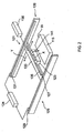
Figure 2 illustrates a perspective view of the imaging unit of the screen printing machine ofFigure 1 ; -
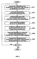
Figure 3 illustrates a flow chart for one mode of operation of the screen printing machine ofFigure 1 ; -
Figure 4 illustrates a flow chart for another mode of operation of the screen printing machine ofFigure 1 ; and -
Figure 5 illustrates a flow chart for a further mode of operation of the screen printing machine ofFigure 1 . - The screen printing machine comprises a
frame support 103 which supports aprinting screen unit 105, which comprises amounting frame 107 and aprinting screen 109 which is mounted thereto, and aprint head 111 which is movable back and forth across theprinting screen 109 to drive a material, such as a solder paste or an adhesive, through a pattern of apertures in theprinting screen 109, and deposit the material onto a workpiece W disposed therebeneath. - The screen printing machine further comprises a
workpiece support 115 which is disposed beneath theprinting screen 109 to support a workpiece W at an operating zone, and aworkpiece transport mechanism 117 which includes a pair oftransport rails workpiece support 115. - The screen printing machine further comprises an
imaging unit 121 for capturing images of fiducials on theprinting screen 109 and the workpiece W. - In this embodiment the
imaging unit 121 comprises avision camera 123 and apositioning mechanism 125 which is operative to position thevision camera 123 in an X-Y plane between theprinting screen 109 and the workpiece W, such that thevision camera 123 captures images of theprinting screen 109 and the workpiece W and detects the fiducials thereon. In this embodiment thepositioning mechanism 125 is configured to move thevision camera 123 through a pre-defined path in the X-Y plane in order to capture a sequence of images which includes all of the fiducials. - In this embodiment the
positioning mechanism 125 comprises an X-Y gantry which includes first andsecond positioning units vision camera 123 in respective ones of orthogonal, X-Y axes, such as to be operable together to provide for positioning of thevision camera 123 in the X-Y plane. - In this embodiment the
first positioning unit 126, here a Y-axis positioning unit, comprises first and second Y-axis positioners bridge member 133, which interconnects the first and second Y-axis positioners single actuator 134 for actuating the Y-axis positioners vision camera 123 in the Y-axis. - In this embodiment the at least one
actuator 134 comprises one of a stepping motor or a servo motor, and includes an encoder which allows for highly-accurate positioning of thevision camera 123. - In this embodiment the
second positioning unit 127, here an X-axis positioning unit, comprises anX-axis positioner 135, which is mounted to thebridge member 133 of the Y-axis positioning unit 126 In orthogonal relation to the Y-axis positioners actuator 136 for actuating theX-axis positioner 135, such as to position thevision camera 123 in the X-axis. - The screen printing machine further comprises an
alignment unit 137, in this embodiment an X-X-Y table, for X, Y and θ alignment of theprinting screen unit 105 relative to theworkpiece support 115 in response to the imaged fiducials. - In this embodiment the
imaging unit 121 further comprises anend effector 141 which is coupled to thevision camera 123, such as to be moved commonly therewith. In this embodiment theend effector 141 has a fixed, offset position relative to the datum of thevision camera 123, which allows for positioning of theend effector 141 in the X-Y plane relative to the workpiece W as required for operation of theend effector 141 on the workpiece W, as will be described in more detail hereinbelow. - In this embodiment the
end effector 141 is a material-dispensing effector for dispensing deposits of a material, typically a viscous material or liquid, such as an adhesive, a solder flux or a solder paste, from a reservoir onto a workpiece W in a desired pattern, with the fluid-dispensing effector being controlled to dispense material deposits in dependence on the movement thereof. - In alternative embodiments the
end effector 141 could be any other kind of effector for operating in relation to a workpiece W, including but not limited to an ink-jetting effector for delivering a liquid to a workpiece W in a desired pattern, a component-mounting effector for mounting components at defined locations on a workpiece W and a laser-etching effector for laser etching a desired pattern in a workpiece W. - The screen printing machine further comprises a
controller 145 for controlling operation of the screen printing machine. - One mode of operation of the above-described screen printing machine will now be described hereinbelow with particular reference to
Figure 3 , where the screen printing machine is operated to provide only for screen printing of material deposits onto a workpiece W. - In a first step (Step S1), a workpiece W, such as a printed circuit board, is transported by the
workpiece transport mechanism 117 to a location above theworkpiece support 115. In this embodiment workpieces W are automatically transported in succession in accordance with the normal control routine of the screen printing machine. - In a second step (Step S2), the
workpiece support 115 is actuated to support the workpiece W as located thereabove by theworkpiece transport mechanism 117. In this embodiment theworkpiece support 115 is operated automatically in accordance with the normal control routine of the screen printing machine. - In a third step (Step S3), the
imaging unit 121 is operated to capture fiducials both on theprinting screen 109 and the workpiece W, in this embodiment by operating thepositioning mechanism 125 to move thevision camera 123 through the X-Y plane between theprinting screen 109 and the workpiece W. In this embodiment theimaging unit 121 is operated automatically in accordance with the normal control routine of the screen printing machine. - In a fourth step (Step S4), the
alignment unit 137 is operated to align theprinting screen 109 relative to the workpiece W, such as to establish common X-Y axes and a 0, 0 datum. In this embodiment thealignment unit 137 is operated automatically in accordance with the normal control routine of the screen printing machine. In this embodiment theprinting screen unit 105 is moved in relation to theworkpiece support 115, such as to align theprinting screen 109 relative to the workpiece W. In an alternative embodiment theworkpiece support 115 could be moved in relation to theprinting screen unit 105, such as to align theprinting screen 109 relative to the workpiece W. - In a fifth step (Step S5), the
workpiece support 115 is operated such as to bring the supported workpiece W into a position adjacent the underside of theprinting screen 109. In this embodiment theworkpiece support 115 is operated in accordance with the normal control routine of the screen printing machine. In this embodiment theworkpiece support 115 is moved in relation to theprinting screen 109 vertically to position a supported workpiece W and theprinting screen 109 in relation to one another. In alternative embodiments theprinting screen 109 could be moved in relation to theworkpiece support 115, or both theprinting screen 109 and theworkpiece support 115 could be moved. - In a sixth step (Step S6), the
print head 111 is operated to drive a material through the apertures in theprinting screen 109 and print a required pattern of deposits of material, such as one of a solder paste or an adhesive, onto the workpiece W. - In a seventh step (Step S7), the
workpiece support 115 is operated to separate the supported workpiece W from the underside of theprinting screen 109. In this embodiment theworkpiece support 115 is operated in accordance with the normal control routine of the screen printing machine. In this embodiment theworkpiece support 115 is moved in relation to theprinting screen 109 vertically to position a supported workpiece W and theprinting screen 109 in relation to one another. In alternative embodiments theprinting screen 109 could be moved in relation to theworkpiece support 115, or both theprinting screen 109 and theworkpiece support 115 could be moved. - In an eighth step (Step S8), the
workpiece support 115 is actuated to return the workpiece W to theworkpiece transport mechanism 117. In this embodiment theworkpiece support 115 is actuated in accordance with the normal control routine of the screen printing machine. - In a ninth step (Step S9), the
workpiece transport mechanism 117 is operated to transport the workpiece W from the screen printing machine automatically in accordance with the normal control routine. - This operation is then repeated for each workpiece W to be processed.
- Another mode of operation of the above-described screen printing machine will now be described hereinbelow with particular reference to
Figure 4 , where the screen printing machine is operated to provide both for screen printing and operation on a workpiece W by theend effector 141, in this embodiment direct dispensing of a material onto the workpiece W. - In a first step (Step S101), a workpiece W, such as a printed circuit board, is transported by the
workpiece transport mechanism 117 to a location above theworkpiece support 115. In this embodiment workpieces W are automatically transported in succession in accordance with the normal control routine of the screen printing machine. - In a second step (Step S102), the
workpiece support 115 is actuated to support the workpiece W as located thereabove by theworkpiece transport mechanism 117. In this embodiment theworkpiece support 115 is operated automatically in accordance with the normal control routine of the screen printing machine. - In a third step (Step S103), the
imaging unit 121 is operated to capture fiducials both on theprinting screen 109 and the workpiece W, in this embodiment by operating thepositioning mechanism 125 to move thevision camera 123 through the X-Y plane between theprinting screen 109 and the workpiece W. In this embodiment theimaging unit 121 is operated automatically in accordance with the normal control routine of the screen printing machine. - In a fourth step (Step S104), the
alignment unit 137 is operated to align theprinting screen 109 relative to the workpiece W, such as to establish common X-Y axes and a 0, 0 datum. In this embodiment thealignment unit 137 is operated automatically in accordance with the normal control routine of the screen printing machine. In this embodiment theprinting screen unit 105 is moved in relation to theworkpiece support 115, such as to align theprinting screen 109 relative to the workpiece W. In an alternative embodiment theworkpiece support 115 could be moved in rotation to theprinting screen unit 105, such as to align theprinting screen 109 relative to the workpiece W. - In a fifth step (Step S105), the
workpiece support 115 is operated such as to bring the supported workpiece W into a position adjacent the underside of theprinting screen 109. In this embodiment theworkpiece support 115 is operated automatically in accordance with the normal control routine of the screen printing machine. In this embodiment theworkpiece support 115 is moved in relation to theprinting screen 109 vertically to position a supported workpiece W and theprinting screen 109 in relation to one another. In alternative embodiments theprinting screen 109 could be moved in relation to theworkpiece support 115, or both theprinting screen 109 and theworkpiece support 115 could be moved. - In a sixth step (Step S106), the
print head 111 is operated to drive a material, such as one of a solder paste or an adhesive, through the apertures in theprinting screen 109 and print a required pattern of deposits of the material onto the workpiece W. - In a seventh step (Step S107), the
workpiece support 115 is operated to separate the supported workpiece W from the underside of theprinting screen 109. In this embodiment theworkpiece support 115 is operated automatically in accordance with the normal control routine of the screen printing machine. In this embodiment theworkpiece support 115 is moved in relation to theprinting screen 109 vertically to position a supported workpiece W and theprinting screen 109 in relation to one another. In alternative embodiments theprinting screen 109 could be moved in relation to theworkpiece support 115, or both theprinting screen 109 and theworkpiece support 115 could be moved. - In an eighth step (Step S108), the
imaging unit 121 is operated such as to move theend effector 141 in the X-Y plane relative to the workpiece W, with theend effector 141 being operated in accordance with a pre-programmed routine, such that theend effector 141 performs the required operation on the workpiece W, in this embodiment in dispensing deposits of a material, such as a solder paste or an adhesive, at required positions and in required volumes. In this embodiment the material deposited by theend effector 141 is the same as that deposited by theprint head 111, such as either one of a solder paste or an adhesive, but in an alternative embodiment the materials can be different, such as a solder paste and an adhesive. - In a ninth step (Step S109), the
workpiece support 115 is actuated to return the workpiece W to theworkpiece transport mechanism 117. In this embodiment theworkpiece support 115 is actuated automatically in accordance with the normal control routine of the screen printing machine. - In a tenth step (Step S110), the
workpiece transport mechanism 117 is operated to transport the workpiece W from the screen printing machine automatically in accordance with the normal control routine. - This operation is then repeated for each workpiece W to be processed.
- A further mode of operation of the above-described screen printing machine will now be described hereinbelow with particular reference to
Figure 5 , where the screen printing machine is operated to provide only for operation on the workpiece W by theend effector 141, in this embodiment the direct dispensing of a material onto the workpiece W. - In a first step (Step S201), a workpiece W, such as a printed circuit board, is transporter by the
workpiece transport mechanism 117 to a location above theworkpiece support 115. In this embodiment workpieces W are automatically transported in succession in accordance with the normal control routine of the screen printing machine. - In a second step (Step S202), the
workpiece support 115 is actuated to support the workpiece W as located thereabove by theworkpiece transport mechanism 117. In this embodiment theworkpiece support 115 is operated automatically in accordance with the normal control routine of the screen printing machine. - In a third step (Step S203), the
imaging unit 121 is operated to capture fiducials both on theprinting screen 109 and the workpiece W, in this embodiment by operating thepositioning mechanism 125 to move thevision camera 123 through the X-Y plane between theprinting screen 109 and the workpiece W. In this embodiment theimaging unit 121 is operated automatically in accordance with the normal control routine of the screen printing machine. - In a fourth step (Step S204), the
alignment unit 137 is operated to align theprinting screen 109 relative to the workpiece W, such as to establish common X-Y axes and a 0, 0 datum. In this embodiment thealignment unit 137 is operated automatically in accordance with the normal control routine of the screen printing machine. In this embodiment theprinting screen unit 105 is moved in relation to theworkpiece support 115, such as to align theprinting screen 109 relative to the workpiece W. In an alternative embodiment theworkpiece support 115 could be moved in relation to theprinting screen unit 105, such as to align theprinting screen 109 relative to the workpiece W. - In a fifth step (Step S205), the
imaging unit 121 is operated such as to move theend effector 141 in the X-Y plane relative to the workpiece W, with theend effector 141 being operated in accordance with a pre-programmed routine, such that theend effector 141 performs the required operation on the workpiece W, in this embodiment in dispensing deposits of a material, such as a solder paste or an adhesive, at required positions and in required volumes. - In a sixth step (Step S206), the
workpiece support 115 is actuated to return the workpiece W to theworkpiece transport mechanism 117. In this embodiment theworkpiece support 115 is actuated automatically in accordance with the normal control routine of the screen printing machine. - In a seventh step (Step S207), the
workpiece transport mechanism 117 is operated to transport the workpiece W from the screen printing machine automatically in accordance with the normal control routine. - This operation is then repeated for each workpiece W to be processed.
- Finally, it will be understood that the present invention has been described in its preferred embodiment and can be modified in many different ways without departing from the scope of the invention as defined by the appended claims.
- In one modification, the
positioners actuator
Claims (15)
- A screen printing machine, comprising:a print head (111) which is operable to drive a material through a printing screen (109) when located in the screen printing machine anddeposit the material onto a workpiece (W), preferably a printed circuit board; andan imaging unit (121) which comprises a vision camera (123) for imaging at least one of the printing screen (109) and the workpiece (W), and a positioning mechanism (125) which is operable to position the vision camera (123);characterized in that the screen printing machine further comprises:an end effector (141) which is operable to perform an operation on the workpiece (W) and is coupled to the vision camera (123), such as to be moved commonly therewith by the positioning mechanism (125);wherein the screen printing machine is operable to print material deposits on the workpiece (W) by operation of the print head (111), and perform an operation on the workpiece (W) at defined positions by actuation of the end effector (141).
- The screen printing machine of claim 1, wherein the end effector (141) has a fixed, offset position relative to the datum of the vision camera (123), and the end effector (141) is positioned by the positioning mechanism (125).
- The screen printing machine of claim 1 or 2, further comprising:a frame support (103) for supporting a printing screen unit (105) which includes a printing screen (109) having a pattern of apertures therein; and preferably further comprising:an alignment unit (137) for aligning the printing screen unit (105) relative to the workpiece (W) in response to features imaged on at least one of the printing screen (109) and the workpiece (W).
- The screen printing machine of any of claims 1 to 3, wherein the positioning mechanism (125) is operable to position the vision camera (123) in an X-Y plane, preferably the positioning mechanism (125) comprises an X-Y gantry, preferably the positioning mechanism (125) comprises first and second positioning units (126, 127), which provide for positioning of the vision camera (123) in respective ones of orthogonal, X-Y axes, such as to be operable together to provide for positioning of the vision camera (123) in the X-Y plane, preferably one, first positioning unit (126) comprises first and second positioners (129, 131), which are mounted in parallel relation, and a bridge member (133), which interconects the first and second positioners (129, 131), and is moved by common operation of the first and second positioners (129, 131) to position the vision camera (123) in one axis, preferably the first positioning unit (126) comprises at least one actuator (134) for actuating the first and second positioners (129, 131) thereof, preferably the at least one actuator (134) comprises one of a steppind motor or a servo motor, preferably the first positioning unit (126) comprises a single actuator (134) for actuating the first and second positioners (129, 131) thereof, and preferably the other, second positioning unit (127) comprises a positioner (135), which is mounted to the bridge member (133) of the first positioning unit (126) in orthogonal relation to the first and second positioners (129, 131) thereof, and is operable to position the vision camera (123) in the other, orthogonal axis, preferably the second positioning unit (127) comprises an actuator (136) for actuating the positioner (135) thereof, preferably the actuator (136) comprises one of a stepping motor or a servo motor.
- The screen printing machine of any of claims 1 to 4, wherein the end effector (141) is a material-dispensing effector for dispensing material deposits onto the workpiece (W) in a desired pattern, preferably the materials are selected from a solder paste, a solder flux and an adhesive, preferably the materials as deposited by the print head (111) and the end effector (141) are one of different or the same.
- The screen printing machine of claim 5, wherein the material-dispensing effector is controlled to dispense material deposits in dependence upon the movement thereof.
- The screen printing machine of any of claims 1 to 4, wherein the end effector (141) is one of an ink-jetting effector for delivering a liquid to the workpiece (W) in a desired pattern, a component-mounting effector for mounting components at defined locations on the workpiece (W) or a laser-etching effector for laser etching a desired pattern in the workpiece (W).
- A method of operating a screen printing machine, which comprises a print head (111) which is operable to drive a material through a printing screen (109) and deposit the material onto a workpiece (W), preferably a printed circuit board, and an imaging unit (121) which comprises a vision camera (123) for imaging at least one of the printing screen (109) and the workpiece (W) and a positioning mechanism (125) which is operable to position the vision camera (123), characterised by the screen printing machine further comprising an end effector (141) which is operable to perform an operation on the workpiece (W) and is coupled to the vision camera (123), such as to be moved commonly therewith, and the method comprising the step of:operating the screen printing machine in one of a first mode in which the print head (111) is driven to print material deposits on a workpiece (W), and a second mode in which the end effector (141) is actuated to perform an operation on the workpiece (W) at defined positions.
- The method of claim 8, wherein, in the second mode, the print head (111) is driven to print material deposits on a workpiece (W) and the end effector (141) is actuated to perform an operation on the workpiece (W) at defined positions, and the screen printing machine operating step preferably comprises the step of:operating the screen printing machine in one of a first mode in which only the print head (111) is driven to print material deposits on a workpiece (W), a second mode in which, preferably successively, the print head (111) is driven to print material deposits on a workpiece (W) and the end effector (141) is actuated to perform an operation on the workpiece (W) at defined positions, and a third mode in which only the end effector (141) is actuated to perform an operation on a workpiece (W) at defined positions.
- The method of claim 8 or 9, wherein the end effector (141) has a fixed, offset position relative to the datum of the vision camera (123), whereby the end effector (141) is positioned by the positioning mechanism (125).
- The method of any of claims 8 to 10, further comprising the steps of:operating the imaging unit (121) to move the vision camera (123) and image features on at least one of the printing screen (109) and the workpiece (W); andaligning the printing screen (119) relative to the workpiece (W) in response to the imaged features.
- The method of any of claims 8 to 11, wherein the end effector (141) is a material-dispensing effector for dispensing material deposits onto the workpiece (W) in a desired pattern, preferably the materials are selected from a solder paste, a solder flux and an adhesive.
- The method of claim 12, wherein the material-dispensing effector is controlled to dispense material deposits in dependence upon the movement thereof.
- The method of claim 12 or 13, wherein the materials as deposited by the print head (111) and the end effector (141) are one of different or the same.
- The method of any of claims 8 to 14, wherein the end effector (141) is one of an ink-jetting effector which is actuated to deliver a liquid to the workpiece (W) in a desired pattern, a component-mounting effector which is actuated to mount components at defined locations on the workpiece (W) or a laser-etching effector which is actuated to laser etch a desired pattern in the workpiece (W).
Applications Claiming Priority (2)
| Application Number | Priority Date | Filing Date | Title |
|---|---|---|---|
| US89067507P | 2007-02-20 | 2007-02-20 | |
| PCT/EP2008/001275 WO2008101663A1 (en) | 2007-02-20 | 2008-02-19 | Screen printing machine and method |
Publications (2)
| Publication Number | Publication Date |
|---|---|
| EP2117845A1 EP2117845A1 (en) | 2009-11-18 |
| EP2117845B1 true EP2117845B1 (en) | 2010-09-22 |
Family
ID=38050428
Family Applications (1)
| Application Number | Title | Priority Date | Filing Date |
|---|---|---|---|
| EP08734584A Active EP2117845B1 (en) | 2007-02-20 | 2008-02-19 | Screen printing machine and method |
Country Status (7)
| Country | Link |
|---|---|
| US (1) | US9327490B2 (en) |
| EP (1) | EP2117845B1 (en) |
| CN (1) | CN101801668B (en) |
| AT (1) | ATE482084T1 (en) |
| DE (1) | DE602008002714D1 (en) |
| GB (1) | GB2446884B (en) |
| WO (1) | WO2008101663A1 (en) |
Families Citing this family (11)
| Publication number | Priority date | Publication date | Assignee | Title |
|---|---|---|---|---|
| DE102007019073A1 (en) * | 2007-04-23 | 2008-11-06 | Ekra Automatisierungssysteme Gmbh Asys Group | Method and device for applying media to flat substrates |
| US8739699B2 (en) * | 2010-12-08 | 2014-06-03 | Illinois Tool Works Inc. | Combination stencil printer and dispenser and related methods |
| US8733244B2 (en) | 2010-12-08 | 2014-05-27 | Illinois Tool Works, Inc. | Methods for depositing viscous material on a substrate with a combination stencil printer and dispenser |
| US8746139B2 (en) | 2010-12-08 | 2014-06-10 | Illinois Tool Works Inc. | Combination stencil printer and dispenser and related methods |
| US8474377B2 (en) | 2010-12-08 | 2013-07-02 | Illinois Tool Works Inc. | Combination stencil printer and dispenser and related methods |
| CN102092178B (en) * | 2010-12-22 | 2012-05-30 | 常州聚诚科技有限公司 | Screen printing device for television panel |
| CN102501615A (en) * | 2011-10-12 | 2012-06-20 | 江苏锐毕利实业有限公司 | Rigid printed circuit board spray printing positioning method |
| US11176635B2 (en) * | 2013-01-25 | 2021-11-16 | Cyberoptics Corporation | Automatic programming of solder paste inspection system |
| CN104551291A (en) * | 2013-10-21 | 2015-04-29 | 泰科电子(上海)有限公司 | Automatic welding system |
| US10137528B2 (en) * | 2014-12-15 | 2018-11-27 | Autodie Llc | Blank etching fixture |
| CN105015151A (en) * | 2015-07-31 | 2015-11-04 | 苏州宏展信息科技有限公司 | Small welding paste screen printer |
Family Cites Families (22)
| Publication number | Priority date | Publication date | Assignee | Title |
|---|---|---|---|---|
| US5110615A (en) * | 1990-01-31 | 1992-05-05 | Asymptotic Technologies, Inc. | Method for dispensing viscous materials a constant height above a workpiece surface |
| JPH05160549A (en) * | 1991-12-11 | 1993-06-25 | Hitachi Ltd | Method and apparatus for removing circuit pattern on printed circuit board by cutter |
| US5792268A (en) * | 1993-07-02 | 1998-08-11 | Sci Systems, Inc. | Printered circuit board screen printer vacuum holding apparatus |
| JPH07185999A (en) * | 1993-12-28 | 1995-07-25 | Seikosha Co Ltd | Drilling device of printed board |
| US5794329A (en) * | 1995-02-27 | 1998-08-18 | Mpm Corporation | Support apparatus for circuit board |
| EP0847682B1 (en) * | 1995-08-30 | 2004-05-19 | Matsushita Electric Industrial Co., Ltd. | Screen printing method and screen printing apparatus |
| IT1283534B1 (en) * | 1996-07-26 | 1998-04-21 | Aisa Spa | MACHINE FOR SCREEN PRINTING OF PLATES EQUIPPED WITH EQUIPMENT FOR RECORDING THE RELATIVE POSITION BETWEEN THE PLATE AND SCREEN |
| US5709905A (en) * | 1997-01-28 | 1998-01-20 | Motorola, Inc. | Apparatus and method for automatic monitoring and control of stencil printing |
| JPH10217427A (en) * | 1997-02-12 | 1998-08-18 | Matsushita Electric Ind Co Ltd | Cream solder printing method and printing machine |
| JP4014270B2 (en) * | 1998-01-06 | 2007-11-28 | 富士機械製造株式会社 | Substrate support pin arrangement method, arrangement inspection method and apparatus |
| JP2000168040A (en) * | 1998-12-04 | 2000-06-20 | Minami Kk | Screen printer |
| US6541063B1 (en) * | 1999-11-04 | 2003-04-01 | Speedline Technologies, Inc. | Calibration of a dispensing system |
| WO2001067835A1 (en) | 2000-03-10 | 2001-09-13 | Ari Co., Ltd. | Apparatus for inspecting solder paste printed on a pcb and supplementary dispensing solder paste |
| US6715413B2 (en) * | 2000-05-09 | 2004-04-06 | Matsushita Electric Industrial Co., Ltd. | Apparatus and method of screen printing |
| US6510356B2 (en) * | 2001-04-02 | 2003-01-21 | Hewlett-Packard Company | Method and apparatus for programming a paste dispensing machine |
| GB2377908A (en) | 2001-05-31 | 2003-01-29 | Blakell Europlacer Ltd | Screen printer for PCB with alignment apparatus |
| US6890050B2 (en) * | 2002-08-20 | 2005-05-10 | Palo Alto Research Center Incorporated | Method for the printing of homogeneous electronic material with a multi-ejector print head |
| KR100540633B1 (en) * | 2003-06-20 | 2006-01-11 | 주식회사 탑 엔지니어링 | Paste applicator and its control method |
| US20050268799A1 (en) * | 2004-06-02 | 2005-12-08 | Speedline Technologies, Inc. | Solder paste lateral flow and redistribution system and methods of same |
| JP2006167991A (en) | 2004-12-13 | 2006-06-29 | Denso Corp | Screen printing apparatus and printing method therefor |
| US20070102477A1 (en) * | 2005-11-10 | 2007-05-10 | Speedline Technologies, Inc. | Imaging system and method for a stencil printer |
| DE102007019073A1 (en) | 2007-04-23 | 2008-11-06 | Ekra Automatisierungssysteme Gmbh Asys Group | Method and device for applying media to flat substrates |
-
2007
- 2007-03-29 GB GB0706091.6A patent/GB2446884B/en not_active Withdrawn - After Issue
-
2008
- 2008-02-19 DE DE602008002714T patent/DE602008002714D1/en active Active
- 2008-02-19 CN CN200880012124.4A patent/CN101801668B/en active Active
- 2008-02-19 WO PCT/EP2008/001275 patent/WO2008101663A1/en not_active Ceased
- 2008-02-19 AT AT08734584T patent/ATE482084T1/en not_active IP Right Cessation
- 2008-02-19 US US12/527,954 patent/US9327490B2/en active Active
- 2008-02-19 EP EP08734584A patent/EP2117845B1/en active Active
Also Published As
| Publication number | Publication date |
|---|---|
| CN101801668B (en) | 2015-09-30 |
| WO2008101663A1 (en) | 2008-08-28 |
| GB2446884A (en) | 2008-08-27 |
| US20100206189A1 (en) | 2010-08-19 |
| EP2117845A1 (en) | 2009-11-18 |
| DE602008002714D1 (en) | 2010-11-04 |
| CN101801668A (en) | 2010-08-11 |
| GB2446884B (en) | 2012-02-01 |
| GB0706091D0 (en) | 2007-05-09 |
| ATE482084T1 (en) | 2010-10-15 |
| US9327490B2 (en) | 2016-05-03 |
| HK1138542A1 (en) | 2010-08-27 |
Similar Documents
| Publication | Publication Date | Title |
|---|---|---|
| US9327490B2 (en) | Screen printing machine and method having vision camera coupled to material-dispensing effector | |
| CN101689048B (en) | Multiplexed control of multi-axis machine with distributed control amplifier | |
| CN101678672B (en) | Method and apparatus for adjusting a substrate support | |
| US8534787B2 (en) | Method and system for printing on a printed circuit board | |
| EP3274173B1 (en) | Stencil printer having stencil shuttle assembly | |
| KR20110061607A (en) | Electronic component mounting system and electronic component mounting method | |
| TWI740286B (en) | Workpiece support assembly, printing machine, alignment method of singulated workpieces and printing method thereof | |
| KR20130132837A (en) | Combination stencil printer and dispenser and related methods | |
| EP2911805B1 (en) | Automated multiple head cleaner for a dispensing system and related method | |
| KR100668132B1 (en) | Reinforcement plate attachment system and method of flexible printed circuit board | |
| EP1261485B1 (en) | Improvements relating to screen printing apparatus | |
| JP2003208210A (en) | Producing machine | |
| JPH09307288A (en) | Electronic component mounting equipment | |
| JP4857828B2 (en) | Screen printing apparatus and screen printing method | |
| WO2017216948A1 (en) | Screen printer | |
| JP4385807B2 (en) | Screen printing machine | |
| HK1138542B (en) | Screen printing machine and method | |
| KR20000073352A (en) | Semiconductor Device | |
| JP3888442B2 (en) | Screen printing apparatus and screen printing method | |
| WO2008098736A2 (en) | Effector module and system for use with a screen printing machine and method of operating a screen printing maschine | |
| JPH10138452A (en) | Screen printing equipment | |
| KR101022704B1 (en) | Dual Screen Printer | |
| JP2010179616A (en) | Screen printing machine and screen printing method | |
| JP2008034758A (en) | Component mounting equipment | |
| HK1155128B (en) | Improvements relating to screen printing apparatus |
Legal Events
| Date | Code | Title | Description |
|---|---|---|---|
| PUAI | Public reference made under article 153(3) epc to a published international application that has entered the european phase |
Free format text: ORIGINAL CODE: 0009012 |
|
| 17P | Request for examination filed |
Effective date: 20090921 |
|
| AK | Designated contracting states |
Kind code of ref document: A1 Designated state(s): AT BE BG CH CY CZ DE DK EE ES FI FR GB GR HR HU IE IS IT LI LT LU LV MC MT NL NO PL PT RO SE SI SK TR |
|
| GRAP | Despatch of communication of intention to grant a patent |
Free format text: ORIGINAL CODE: EPIDOSNIGR1 |
|
| DAX | Request for extension of the european patent (deleted) | ||
| GRAS | Grant fee paid |
Free format text: ORIGINAL CODE: EPIDOSNIGR3 |
|
| RAP1 | Party data changed (applicant data changed or rights of an application transferred) |
Owner name: DTG INTERNATIONAL GMBH |
|
| GRAA | (expected) grant |
Free format text: ORIGINAL CODE: 0009210 |
|
| REG | Reference to a national code |
Ref country code: HK Ref legal event code: DE Ref document number: 1138542 Country of ref document: HK |
|
| AK | Designated contracting states |
Kind code of ref document: B1 Designated state(s): AT BE BG CH CY CZ DE DK EE ES FI FR GB GR HR HU IE IS IT LI LT LU LV MC MT NL NO PL PT RO SE SI SK TR |
|
| REG | Reference to a national code |
Ref country code: GB Ref legal event code: FG4D |
|
| REG | Reference to a national code |
Ref country code: CH Ref legal event code: EP |
|
| REG | Reference to a national code |
Ref country code: IE Ref legal event code: FG4D |
|
| REF | Corresponds to: |
Ref document number: 602008002714 Country of ref document: DE Date of ref document: 20101104 Kind code of ref document: P |
|
| REG | Reference to a national code |
Ref country code: NL Ref legal event code: T3 |
|
| REG | Reference to a national code |
Ref country code: HK Ref legal event code: GR Ref document number: 1138542 Country of ref document: HK |
|
| PG25 | Lapsed in a contracting state [announced via postgrant information from national office to epo] |
Ref country code: NO Free format text: LAPSE BECAUSE OF FAILURE TO SUBMIT A TRANSLATION OF THE DESCRIPTION OR TO PAY THE FEE WITHIN THE PRESCRIBED TIME-LIMIT Effective date: 20101222 Ref country code: LT Free format text: LAPSE BECAUSE OF FAILURE TO SUBMIT A TRANSLATION OF THE DESCRIPTION OR TO PAY THE FEE WITHIN THE PRESCRIBED TIME-LIMIT Effective date: 20100922 Ref country code: AT Free format text: LAPSE BECAUSE OF FAILURE TO SUBMIT A TRANSLATION OF THE DESCRIPTION OR TO PAY THE FEE WITHIN THE PRESCRIBED TIME-LIMIT Effective date: 20100922 Ref country code: FI Free format text: LAPSE BECAUSE OF FAILURE TO SUBMIT A TRANSLATION OF THE DESCRIPTION OR TO PAY THE FEE WITHIN THE PRESCRIBED TIME-LIMIT Effective date: 20100922 |
|
| LTIE | Lt: invalidation of european patent or patent extension |
Effective date: 20100922 |
|
| PG25 | Lapsed in a contracting state [announced via postgrant information from national office to epo] |
Ref country code: SI Free format text: LAPSE BECAUSE OF FAILURE TO SUBMIT A TRANSLATION OF THE DESCRIPTION OR TO PAY THE FEE WITHIN THE PRESCRIBED TIME-LIMIT Effective date: 20100922 Ref country code: HR Free format text: LAPSE BECAUSE OF FAILURE TO SUBMIT A TRANSLATION OF THE DESCRIPTION OR TO PAY THE FEE WITHIN THE PRESCRIBED TIME-LIMIT Effective date: 20100922 Ref country code: PL Free format text: LAPSE BECAUSE OF FAILURE TO SUBMIT A TRANSLATION OF THE DESCRIPTION OR TO PAY THE FEE WITHIN THE PRESCRIBED TIME-LIMIT Effective date: 20100922 |
|
| PG25 | Lapsed in a contracting state [announced via postgrant information from national office to epo] |
Ref country code: LV Free format text: LAPSE BECAUSE OF FAILURE TO SUBMIT A TRANSLATION OF THE DESCRIPTION OR TO PAY THE FEE WITHIN THE PRESCRIBED TIME-LIMIT Effective date: 20100922 Ref country code: GR Free format text: LAPSE BECAUSE OF FAILURE TO SUBMIT A TRANSLATION OF THE DESCRIPTION OR TO PAY THE FEE WITHIN THE PRESCRIBED TIME-LIMIT Effective date: 20101223 Ref country code: SE Free format text: LAPSE BECAUSE OF FAILURE TO SUBMIT A TRANSLATION OF THE DESCRIPTION OR TO PAY THE FEE WITHIN THE PRESCRIBED TIME-LIMIT Effective date: 20100922 |
|
| PG25 | Lapsed in a contracting state [announced via postgrant information from national office to epo] |
Ref country code: SK Free format text: LAPSE BECAUSE OF FAILURE TO SUBMIT A TRANSLATION OF THE DESCRIPTION OR TO PAY THE FEE WITHIN THE PRESCRIBED TIME-LIMIT Effective date: 20100922 Ref country code: CZ Free format text: LAPSE BECAUSE OF FAILURE TO SUBMIT A TRANSLATION OF THE DESCRIPTION OR TO PAY THE FEE WITHIN THE PRESCRIBED TIME-LIMIT Effective date: 20100922 Ref country code: RO Free format text: LAPSE BECAUSE OF FAILURE TO SUBMIT A TRANSLATION OF THE DESCRIPTION OR TO PAY THE FEE WITHIN THE PRESCRIBED TIME-LIMIT Effective date: 20100922 Ref country code: IS Free format text: LAPSE BECAUSE OF FAILURE TO SUBMIT A TRANSLATION OF THE DESCRIPTION OR TO PAY THE FEE WITHIN THE PRESCRIBED TIME-LIMIT Effective date: 20110122 Ref country code: PT Free format text: LAPSE BECAUSE OF FAILURE TO SUBMIT A TRANSLATION OF THE DESCRIPTION OR TO PAY THE FEE WITHIN THE PRESCRIBED TIME-LIMIT Effective date: 20110124 Ref country code: EE Free format text: LAPSE BECAUSE OF FAILURE TO SUBMIT A TRANSLATION OF THE DESCRIPTION OR TO PAY THE FEE WITHIN THE PRESCRIBED TIME-LIMIT Effective date: 20100922 |
|
| PG25 | Lapsed in a contracting state [announced via postgrant information from national office to epo] |
Ref country code: BE Free format text: LAPSE BECAUSE OF FAILURE TO SUBMIT A TRANSLATION OF THE DESCRIPTION OR TO PAY THE FEE WITHIN THE PRESCRIBED TIME-LIMIT Effective date: 20100922 |
|
| PG25 | Lapsed in a contracting state [announced via postgrant information from national office to epo] |
Ref country code: ES Free format text: LAPSE BECAUSE OF FAILURE TO SUBMIT A TRANSLATION OF THE DESCRIPTION OR TO PAY THE FEE WITHIN THE PRESCRIBED TIME-LIMIT Effective date: 20110102 |
|
| PLBE | No opposition filed within time limit |
Free format text: ORIGINAL CODE: 0009261 |
|
| STAA | Information on the status of an ep patent application or granted ep patent |
Free format text: STATUS: NO OPPOSITION FILED WITHIN TIME LIMIT |
|
| 26N | No opposition filed |
Effective date: 20110623 |
|
| PG25 | Lapsed in a contracting state [announced via postgrant information from national office to epo] |
Ref country code: DK Free format text: LAPSE BECAUSE OF FAILURE TO SUBMIT A TRANSLATION OF THE DESCRIPTION OR TO PAY THE FEE WITHIN THE PRESCRIBED TIME-LIMIT Effective date: 20100922 |
|
| PG25 | Lapsed in a contracting state [announced via postgrant information from national office to epo] |
Ref country code: MC Free format text: LAPSE BECAUSE OF NON-PAYMENT OF DUE FEES Effective date: 20110228 |
|
| REG | Reference to a national code |
Ref country code: DE Ref legal event code: R097 Ref document number: 602008002714 Country of ref document: DE Effective date: 20110623 |
|
| REG | Reference to a national code |
Ref country code: IE Ref legal event code: MM4A |
|
| PG25 | Lapsed in a contracting state [announced via postgrant information from national office to epo] |
Ref country code: MT Free format text: LAPSE BECAUSE OF FAILURE TO SUBMIT A TRANSLATION OF THE DESCRIPTION OR TO PAY THE FEE WITHIN THE PRESCRIBED TIME-LIMIT Effective date: 20100922 |
|
| PG25 | Lapsed in a contracting state [announced via postgrant information from national office to epo] |
Ref country code: IE Free format text: LAPSE BECAUSE OF NON-PAYMENT OF DUE FEES Effective date: 20110219 |
|
| REG | Reference to a national code |
Ref country code: CH Ref legal event code: PL |
|
| PG25 | Lapsed in a contracting state [announced via postgrant information from national office to epo] |
Ref country code: CH Free format text: LAPSE BECAUSE OF NON-PAYMENT OF DUE FEES Effective date: 20120229 Ref country code: LI Free format text: LAPSE BECAUSE OF NON-PAYMENT OF DUE FEES Effective date: 20120229 |
|
| PG25 | Lapsed in a contracting state [announced via postgrant information from national office to epo] |
Ref country code: CY Free format text: LAPSE BECAUSE OF FAILURE TO SUBMIT A TRANSLATION OF THE DESCRIPTION OR TO PAY THE FEE WITHIN THE PRESCRIBED TIME-LIMIT Effective date: 20100922 Ref country code: LU Free format text: LAPSE BECAUSE OF NON-PAYMENT OF DUE FEES Effective date: 20110219 |
|
| PG25 | Lapsed in a contracting state [announced via postgrant information from national office to epo] |
Ref country code: BG Free format text: LAPSE BECAUSE OF FAILURE TO SUBMIT A TRANSLATION OF THE DESCRIPTION OR TO PAY THE FEE WITHIN THE PRESCRIBED TIME-LIMIT Effective date: 20101222 Ref country code: TR Free format text: LAPSE BECAUSE OF FAILURE TO SUBMIT A TRANSLATION OF THE DESCRIPTION OR TO PAY THE FEE WITHIN THE PRESCRIBED TIME-LIMIT Effective date: 20100922 |
|
| PG25 | Lapsed in a contracting state [announced via postgrant information from national office to epo] |
Ref country code: HU Free format text: LAPSE BECAUSE OF FAILURE TO SUBMIT A TRANSLATION OF THE DESCRIPTION OR TO PAY THE FEE WITHIN THE PRESCRIBED TIME-LIMIT Effective date: 20100922 |
|
| REG | Reference to a national code |
Ref country code: FR Ref legal event code: PLFP Year of fee payment: 9 |
|
| REG | Reference to a national code |
Ref country code: FR Ref legal event code: PLFP Year of fee payment: 10 |
|
| REG | Reference to a national code |
Ref country code: DE Ref legal event code: R081 Ref document number: 602008002714 Country of ref document: DE Owner name: ASM ASSEMBLY SYSTEMS SINGAPORE PTE LTD., SG Free format text: FORMER OWNER: DTG INTERNATIONAL GMBH, ZUERICH, CH Ref country code: DE Ref legal event code: R082 Ref document number: 602008002714 Country of ref document: DE Representative=s name: HENTRICH, SWEN, DIPL.-PHYS. DR.RER.NAT., DE |
|
| REG | Reference to a national code |
Ref country code: GB Ref legal event code: 732E Free format text: REGISTERED BETWEEN 20170817 AND 20170823 |
|
| REG | Reference to a national code |
Ref country code: NL Ref legal event code: HC Owner name: ASM ASSEMBLY SYSTEMS SWITZERLAND GMBH; CH Free format text: DETAILS ASSIGNMENT: CHANGE OF OWNER(S), CHANGE OF OWNER(S) NAME; FORMER OWNER NAME: DTG INTERNATIONAL GMBH Effective date: 20170712 Ref country code: NL Ref legal event code: PD Owner name: ASM ASSEMBLY SYSTEMS SINGAPORE PTE. LTD.; SG Free format text: DETAILS ASSIGNMENT: CHANGE OF OWNER(S), ASSIGNMENT; FORMER OWNER NAME: ASM ASSEMBLY SYSTEMS SWITZERLAND GMBH Effective date: 20170712 |
|
| REG | Reference to a national code |
Ref country code: DE Ref legal event code: R082 Ref document number: 602008002714 Country of ref document: DE |
|
| REG | Reference to a national code |
Ref country code: FR Ref legal event code: CD Owner name: ASM ASSEMBLY SYSTEMS SINGAPORE PTE. LTD., SG Effective date: 20171122 |
|
| REG | Reference to a national code |
Ref country code: FR Ref legal event code: TP Owner name: ASM ASSEMBLY SYSTEMS SINGAPORE PTE. LTD., SG Effective date: 20171127 |
|
| REG | Reference to a national code |
Ref country code: FR Ref legal event code: PLFP Year of fee payment: 11 |
|
| REG | Reference to a national code |
Ref country code: NL Ref legal event code: HC Owner name: ASMPT SMT SINGAPORE PTE. LTD.; SG Free format text: DETAILS ASSIGNMENT: CHANGE OF OWNER(S), CHANGE OF OWNER(S) NAME; FORMER OWNER NAME: DTG INTERNATIONAL GMBH Effective date: 20230130 |
|
| REG | Reference to a national code |
Ref country code: DE Ref legal event code: R081 Ref document number: 602008002714 Country of ref document: DE Owner name: ASMPT SMT SINGAPORE PTE. LTD., SG Free format text: FORMER OWNER: ASM ASSEMBLY SYSTEMS SINGAPORE PTE LTD., SINGAPUR, SG |
|
| P01 | Opt-out of the competence of the unified patent court (upc) registered |
Effective date: 20230530 |
|
| PGFP | Annual fee paid to national office [announced via postgrant information from national office to epo] |
Ref country code: NL Payment date: 20260218 Year of fee payment: 19 |
|
| PGFP | Annual fee paid to national office [announced via postgrant information from national office to epo] |
Ref country code: GB Payment date: 20260219 Year of fee payment: 19 |
|
| PGFP | Annual fee paid to national office [announced via postgrant information from national office to epo] |
Ref country code: DE Payment date: 20260218 Year of fee payment: 19 |
|
| PGFP | Annual fee paid to national office [announced via postgrant information from national office to epo] |
Ref country code: IT Payment date: 20260224 Year of fee payment: 19 |
|
| PGFP | Annual fee paid to national office [announced via postgrant information from national office to epo] |
Ref country code: FR Payment date: 20260218 Year of fee payment: 19 |