EP2117367B1 - Surgical helmet and cover assembly, methods of making and using the same - Google Patents
Surgical helmet and cover assembly, methods of making and using the same Download PDFInfo
- Publication number
- EP2117367B1 EP2117367B1 EP08726115A EP08726115A EP2117367B1 EP 2117367 B1 EP2117367 B1 EP 2117367B1 EP 08726115 A EP08726115 A EP 08726115A EP 08726115 A EP08726115 A EP 08726115A EP 2117367 B1 EP2117367 B1 EP 2117367B1
- Authority
- EP
- European Patent Office
- Prior art keywords
- hood
- helmet
- air
- surgical
- face shield
- Prior art date
- Legal status (The legal status is an assumption and is not a legal conclusion. Google has not performed a legal analysis and makes no representation as to the accuracy of the status listed.)
- Active
Links
Images







Classifications
-
- A—HUMAN NECESSITIES
- A42—HEADWEAR
- A42B—HATS; HEAD COVERINGS
- A42B3/00—Helmets; Helmet covers ; Other protective head coverings
- A42B3/003—Helmet covers
-
- A—HUMAN NECESSITIES
- A41—WEARING APPAREL
- A41D—OUTERWEAR; PROTECTIVE GARMENTS; ACCESSORIES
- A41D13/00—Professional, industrial or sporting protective garments, e.g. surgeons' gowns or garments protecting against blows or punches
- A41D13/05—Professional, industrial or sporting protective garments, e.g. surgeons' gowns or garments protecting against blows or punches protecting only a particular body part
- A41D13/11—Protective face masks, e.g. for surgical use, or for use in foul atmospheres
- A41D13/1107—Protective face masks, e.g. for surgical use, or for use in foul atmospheres characterised by their shape
- A41D13/1153—Protective face masks, e.g. for surgical use, or for use in foul atmospheres characterised by their shape with a hood
-
- A—HUMAN NECESSITIES
- A42—HEADWEAR
- A42B—HATS; HEAD COVERINGS
- A42B3/00—Helmets; Helmet covers ; Other protective head coverings
- A42B3/04—Parts, details or accessories of helmets
- A42B3/28—Ventilating arrangements
- A42B3/286—Ventilating arrangements with forced flow, e.g. by a fan
-
- A—HUMAN NECESSITIES
- A62—LIFE-SAVING; FIRE-FIGHTING
- A62B—DEVICES, APPARATUS OR METHODS FOR LIFE-SAVING
- A62B17/00—Protective clothing affording protection against heat or harmful chemical agents or for use at high altitudes
- A62B17/04—Hoods
-
- A—HUMAN NECESSITIES
- A62—LIFE-SAVING; FIRE-FIGHTING
- A62B—DEVICES, APPARATUS OR METHODS FOR LIFE-SAVING
- A62B18/00—Breathing masks or helmets, e.g. affording protection against chemical agents or for use at high altitudes or incorporating a pump or compressor for reducing the inhalation effort
- A62B18/04—Gas helmets
- A62B18/045—Gas helmets with fans for delivering air for breathing mounted in or on the helmet
Definitions
- the present invention relates generally to surgical helmets and surgical helmet components suitable for use in an operating room setting, methods of making surgical helmets and surgical helmet components, and methods of using surgical helmets and surgical helmet components, for example, in an operating room setting.
- a variety of disposable and reusable surgical helmets are used in operating rooms. Helmets are used to protect and/or cover a surgeon or other operating room personnel such as during a surgical procedure. During surgical procedures, it is important for a helmet to provide a barrier between the surgeon (or other operating room personnel) and the patient so as to protect the surgeon (or other operating room personnel) from exposure to body fluids and any other contaminants. Consequently, there is a tendency to for helmets and helmet components to be formed from barrier materials without additional considerations such as carbon dioxide build-up within the helmet during a surgical procedure.
- US 2003/0101505 A1 provides a head gear apparatus that moves air to cool a caregiver's head.
- the head gear apparatus includes a helmet and has a shell configured to rest upon the head of a user and a fan housing movably coupled to the shell.
- a fan is positioned to lie within the fan housing and moves with the fan housing relative to the shell and a garment selectively coupled to the helmet.
- the garment includes a face shield.
- US 6,374,823 B1 discloses a protective structure for use in a surgical environment including a face shield formed as a transparent tube to extend around the wearer's head and a cloth head covering extending above and around the face shield, with a viewing aperture being formed in the head covering to extend in front of the wearer's face, and with the head covering being attached to the face shield around the viewing aperture.
- a support structure extends from a rear portion of the face shield to a front portion thereof, forming an air channel through which air is moved by an internal fan between an air inlet aperture in the head covering at the rear of the support structure and an air outlet at the front of the support structure above the wearer's face.
- the present invention is directed to helmets and helmet components suitable for use in an operating room setting, an emergency room setting, a hospital setting, or a lab.
- the helmets and helmet components of the present invention provide one or more of the following features: (i) superior barrier protection to a surgeon (or other operating room personnel) during a surgical procedure, (ii) a desired degree of air flow and controlled directional air flow through the helmet so as to minimize the potential for carbon dioxide buildup within the helmet, (iii) a desired minimal helmet weight, and (iv) an optional integrated battery pack positioned within the helmet.
- a surgical helmet component comprising a surgical helmet cover assembly comprising a hood sized to extend over a surgical helmet, the hood comprising a first hood material having (i) a face shield aperture completely surrounded by the first hood material, (ii) at least one hood air inlet completely surrounded by the first hood material, (iii) at least one hood air outlet completely surrounded by the first hood material, and (iv) a hood opening completely surrounded by the first hood material, the hood opening being sized so that the hood can be positioned over and onto a surgical helmet; a transparent face shield positioned over the face shield aperture and bonded to the fist hood material along an outer periphery of the face shield aperture so as to form a sterile barrier along the outer periphery between an interior volume of the hood and an exterior surface of the hood; characterised in that it further comprises multiple pieces of additional hood material positioned over the at least one
- a surgical helmet comprising a frame operatively adapted to surround at least a portion of a person's head; a transparent face shield attached to the frame and positioned along a front side of the helmet; an air channel having at least one air channel inlet and at least one air channel outlet, the at least one air channel outlet being positioned so as to provide air to a space bound by an inner surface of the transparent face shield; a fan in fluid communication with the air channel, the fan being operatively adapted to move air through the air channel; a hood comprising a first hood material having (i) a face shield aperture completely surrounded by the first hood material and sized so that an outer periphery of the face shield aperture surrounds the transparent face shield, (ii) at least one hood air inlet completely surrounded by the first hood material and positioned to align with the at least one air channel inlet, (iii) at least one hood air outlet completely surrounded by the first hood material
- the present invention is also directed to a surgical outfit comprising at least one surgical helmet.
- the present invention is even further directed to methods of reducing an amount of carbon dioxide within a surgical outfit during use.
- the method comprises providing a surgical outfit of the present invention (such as the above-described surgical outfit or any surgical outfit described below), and cutting on the fan to provide an air flow path through at least one hood air inlet in a helmet, to at least one air channel inlet, through an air channel, out of at least one air channel outlet into a region of the helmet bound by a transparent face shield, and out of the helmet through at least one hood air outlet.
- the surgical outfit of the present invention is capable of reducing an amount of carbon dioxide within the surgical outfit, during use, to below about 2500 ppm, and even below about 1800 ppm.
- the present invention is directed to surgical helmets and surgical helmet components suitable for use in any environment in which a surgical helmet is typically used including, but not limited to, an operating room setting, an emergency room setting, a hospital setting, a lab, a clean room, etc.
- the surgical helmets and surgical helmet components of the present invention are particularly useful in providing a barrier between a surgeon and a surgical site of a patient.
- the present invention is directed to a surgical helmet cover assembly comprising a hood sized to extend over a surgical helmet, the hood comprising a first hood material having (i) a face shield aperture completely surrounded by the first hood material, (ii) at least one hood air inlet completely surrounded by the first hood material, (iii) at least one hood air outlet completely surrounded by the first hood material, and (iv) a hood opening completely surrounded by the first hood material, the hood opening being sized so that the hood can be positioned over and onto a surgical helmet; a transparent face shield positioned over the face shield aperture and bonded to the first hood material along an outer periphery of the face shield aperture so as to form a sterile barrier along the outer periphery between an interior volume of the hood and an exterior surface of the hood; and multiple pieces of additional hood material positioned over the at least one hood air inlet and the at least one hood air outlet, wherein
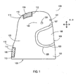
- exemplary surgical helmet cover assembly 100 comprises hood 101 sized to extend over a surgical helmet (not shown), wherein hood 101 comprises first hood material 102 having (i) a face shield aperture 103 completely surrounded by first hood material 102, (ii) at least one hood air inlet 104 completely surrounded by first hood material 102, (iii) at least one hood air outlet 105 completely surrounded by first hood material 102, and (iv) a hood opening 136 completely surrounded by first hood material 102.
- Hood opening 136 is sized so that hood opening 136 can be positioned over and onto a surgical helmet (not shown).
- Exemplary surgical helmet cover assembly 100 further comprises a transparent face shield 106 positioned over face shield aperture 103 and bonded to first hood material 102 along an outer periphery 107 of face shield aperture 103 so as to form a sterile barrier along outer periphery 107 between an interior volume (e.g., interior volume 108 shown in FIG. 3 ) of hood 101 and an exterior surface 109 of hood 101.
- a transparent face shield 106 positioned over face shield aperture 103 and bonded to first hood material 102 along an outer periphery 107 of face shield aperture 103 so as to form a sterile barrier along outer periphery 107 between an interior volume (e.g., interior volume 108 shown in FIG. 3 ) of hood 101 and an exterior surface 109 of hood 101.
- Exemplary surgical helmet cover assembly 100 further comprises multiple pieces of additional hood material 110 and 111 positioned over the at least one hood air inlet 104 and the at least one hood air outlet 105 respectively, wherein each of the multiple pieces of additional hood material 110 and 111 (i) are bonded to first hood material 102 along an outer periphery 112 and 113 of each of the at least one hood air inlet 104 and the at least one hood air outlet 105 respectively, and (ii) have an air flow permeability greater than first hood material 102.
- hood 101 of exemplary surgical helmet cover assembly 100 may further comprise a resealable fan switch knob opening 124 completely surrounded by first hood material 102.
- resealable fan switch knob opening 124 (i) is sized so that a fan switch knob of a surgical helmet (see, for example, fan switch knob 23 of exemplary surgical helmet 10 shown in FIG. 10B ) can fit therethrough, and (ii) is positioned along an outer surface 140 of hood 101, desirably, above a lower edge 125 of transparent face shield 106, and more desirably, along an outer surface of hood 101 above transparent face shield 106.
- FIG. 2A depicts a frontal view of exemplary surgical helmet cover assembly 100 shown in FIG. 1 .
- transparent face shield 106 is positioned along a front side 114 of hood 101 over face shield aperture 103. Further, transparent face shield 106 is completely surrounded by first hood material 102.
- hood 101 may further comprises a resealable frame adjustment knob opening 121 completely surrounded by first hood material 102, wherein resealable frame adjustment knob opening 121 (i) is sized so that a frame adjustment knob of a surgical helmet (see, for example, frame adjustment knob 14 of exemplary surgical helmet 10 shown in FIG.
- hood 101 of exemplary surgical helmet cover assembly 100 does not have to comprise resealable frame adjustment knob opening 121 given that surgical helmet/frame adjustments are typically made on the helmet prior to attachment of exemplary surgical helmet cover assembly 100 to the surgical helmet.
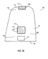
- Hood 101 of exemplary surgical helmet cover assembly 100 typically comprises a single hood air inlet 104 positioned along an upper rear portion 115 of hood 101, and one or more hood air outlets 105 positioned along a rear side 116 of hood 101 below single hood air inlet 104 and opposite transparent face shield 106 (e.g., in a neck region of the wearer).
- hood 101 comprises two separate hood air outlets 105 positioned side-by-side along rear side 115 of hood 101 below single hood air inlet 104 and opposite transparent face shield 106 (i.e., instead of a single hood air outlet 105 as shown in FIG. 2B , two hood air outlets 105 would be present in a neck region of the wearer similar to hood air outlets 62 shown in FIG. 7 ).
- hood 101 may further comprise a pocket 117 positioned along rear side 116 of hood 101, wherein pocket 117 is sized so as to accept a battery pack (not shown) therein.
- pocket 117 may be positioned along any portion of an outer surface 140 of hood 101, although pocket 117 is desirably positioned below at least one hood air inlet 104 and below at least one hood air outlet 105 as shown in FIG. 2B .
- hood 101 may further comprise a slot in first hood material 102, wherein the slot is desirably positioned within pocket 117 and sized so that a battery pack connector (not shown) can extend through the slot.
- pocket 117 may be used to store a supplemental battery, with a primary battery being positioned within a frame component or air channel containing member (e.g., foam member) of a surgical helmet as described further below.
- FIG. 3 depicts a cross-sectional view of exemplary surgical helmet cover assembly 100 of FIG. 1 as viewed perpendicularly to plane A-A shown in FIG. 1 .
- exemplary surgical helmet cover assembly 100 may further comprise one or more attachment members 118 positioned along (i) an inner surface 119 of hood 101, (ii) an inner surface 120 of transparent face shield 106, or (iii) both (i) and (ii).
- One or more attachment members 118 are operatively adapted to connect exemplary surgical helmet cover assembly 100 to a surgical helmet (for example, exemplary surgical helmet 200 shown in FIG. 4 ).
- Attachment members 118 may comprise a variety of materials including, but not limited to, hook and/or loop material, magnets, adhesive tape, etc.
- exemplary surgical helmet cover assembly 100 may further comprise one or more adjustable face shield spacers 127 positioned along an inner surface 120 of transparent face shield 106.
- the one or more adjustable face shield spacers 127 are operatively adapted to alter a line of curvature extending from one side of transparent face shield 106 (i.e., side 128 shown in FIG. 2A ) to an opposite side of transparent face shield 106 (i.e., side 129 shown in FIG. 2A ).
- any member e.g., a screw-like member capable of adjusting a distance between transparent face shield 106 and a surgical helmet component, for example, as a frame or air channel containing member (described further below), may be used for each adjustable face shield spacer 127. Alteration of the line of curvature of transparent face shield 106 may help reduce an amount of glare when viewing a surgical site through transparent face shield 106.
- First hood material 102 typically comprises a fluid/blood barrier material.
- the fluid/blood barrier material typically comprises a single layer of nonwoven fabric or a single layer of nonwoven fabric/film laminate having little or no air permeability.
- the fluid/blood barrier material has an air permeability (i.e., as measured using ASTM D737 test method) of less than about 17.1 cm 3 /min/cm 2 of material (0.562 ft 3 /min/ft 2 of material).
- the fluid/blood barrier material comprises a breathable viral barrier (BVB) fabric commercially available from Ahlstrom Corporation (Alpharetta, GA), such as a BVB trilaminate polypropylene material having a basis weight of about 70 grams per square meter (gsm) and a thickness of about 0.35 millimeters (mm).
- BVB breathable viral barrier
- Multiple pieces of additional hood material 110 and 111 may comprise a variety of air filtration (i.e., air permeable) materials.
- each of multiple pieces of additional hood material 110 and 111 comprises a nonwoven fabric, such as a spunbonded fabric, a spunlaced fabric, a needle-punched fabric, a melt-blown fabric, or any combination thereof.
- each of multiple pieces of additional hood material 110 and 111 comprises a spunbonded fabric, such as a nylon spunbonded fabric commercially available under the trade designation CEREX ® from Cerex Advanced Fabrics, Inc. (Pensacola, FL).
- each of multiple pieces of additional hood material 110 and 111 comprises a nonwoven fabric having a fabric basis weight of less than 100 gsm (more typically, from about 9 gsm to about 95 gsm, even more typically, from about 15 gsm to about 50 gsm) and a fabric thickness of less than about 150 microns ( ⁇ m), typically, from about 75 ⁇ m to about 100 ⁇ m.
- first hood material 102 typically comprises one of the above-mentioned fluid/blood barrier materials having a basis weight of greater than about 50 gsm) (more typically, from about 50 gsm to about 100 gsm, even more typically, from about 70 gsm to about 80 gsm) and a fabric thickness of greater than about 0.25 mm, typically, from about 0.35 mm to about 0.5 mm.
- the above-described surgical helmet cover assemblies of the present invention are typically disposable, and may be used with disposable or reuseable surgical helmets of the present invention such as the surgical helmets described below.
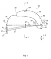
- One exemplary surgical helmet of the present invention is shown in FIG. 4 .
- exemplary surgical helmet 200 of the present invention comprises a frame 201 operatively adapted to surround at least a portion of a person's head (not shown); an air channel containing member 202 (e.g., a foam member) having an air channel therein (see, air channel 210 in FIG. 4B ), wherein the air channel has at least one air channel inlet 203 and at least one air channel outlet 204, the at least one air channel outlet 204 being positioned so as to provide air to a space bound by (i) the face of a wearer (not shown) and (ii) an inner surface of a transparent face shield (not shown) when present; and a fan (see, fan 213 in FIG. 4A ) in fluid communication with the air channel (not shown), the fan being operatively adapted to move air through the air channel of air channel containing member 202.
- an air channel containing member 202 e.g., a foam member having an air channel therein (see, air channel 210 in FIG. 4B ), wherein
- exemplary surgical helmet 200 may further comprise a frame adjustment knob 205 that can be used to adjust the dimensions of frame 201 so as to better fit onto the head of a user (not shown).
- Knob 205 can be used to adjust a length (i.e., a first dimension extending from front side 206 to rear side 207) and a width of frame 201 (i.e., a dimension extending perpendicular to the first dimension, e.g., across a width of exemplary surgical helmet 200).
- Exemplary surgical helmet 200 may further comprise a fan adjustment knob 205 that can be used to (i) cut "on” or “off” the fan, (ii) change a speed of the fan, or (iii) both (i) and (ii).
- Exemplary surgical helmet 200 may further comprise frontal pad 209 and rear pad 211 along opposite ends of frame 201 to provide additional comfort to a user (not shown).
- exemplary surgical helmet 200 may further comprise one or more adjustable helmet spacers 227, which, like adjustable face shield spacers 127 described above, are operatively adapted to alter a line of curvature extending from one side of a transparent face shield to an opposite side of transparent face shield so as to help reduce an amount of glare when viewing a surgical site through the transparent face shield.
- Exemplary surgical helmet 200 may be used in combination with a detachable or permanently attached surgical helmet cover assembly, such as exemplary surgical helmet cover assembly 100 discussed above.
- exemplary surgical helmet 200 may comprise one or more attachment members 218 that assist in attaching a surgical helmet cover assembly, such as exemplary surgical helmet cover assembly 100 discussed above, to exemplary surgical helmet 200.
- attachment members 118 of exemplary surgical helmet cover assembly 100 shown in FIG. 3 and attachment members 218 of exemplary surgical helmet 200 may comprise, for example, hook and loop material, respectively, to aid in the attachment of exemplary surgical helmet cover assembly 100 to exemplary surgical helmet 200.
- attachment members 118 and 218 may comprise magnets, adhesive tape, or any other type of attachment material.
- FIG. 4A depicts a top view of exemplary surgical helmet 200 shown in FIG. 4 as viewed from above exemplary surgical helmet 200.
- air channel containing member 202 has at least one air channel inlet 203 positioned along an upper rear portion 214 of air channel containing member 202, and a fan 213 in fluid communication with the air channel (not shown).
- Fan 213 is positioned within slot 212 and is operatively adapted to move air through the air channel of air channel containing member 202 in a direction as shown by arrow A in FIG. 4A .
- air channel containing member 202 may further comprise an indention 215 sized to house a primary battery pack (not shown) for supplying electricity to fan 213.
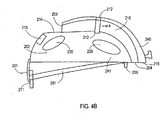
- FIG. 4B depicts a cross-sectional view of exemplary surgical helmet 200 shown in FIG. 4 as viewed perpendicularly to plane B-B shown in FIG. 4 so as to show air channel 210.
- air channel 210 of air channel containing member 202 extends from at least one air channel inlet 203 positioned along an upper rear portion 214 of air channel containing member 202 to air channel outlet 204 positioned along a front portion 216 of air channel containing member 202.
- Slot 212 which is sized so as to house fan 213 (not shown), desirably has a width slightly greater than a width of air channel 210 and a height slightly greater than a height of air channel 210, so that fan 213 fits snugly within slot 212 and does not move out of slot 212 during operation.
- air channel containing member 202 comprises a foam member as discussed further below
- slot 212 of air channel containing member 202 also absorbs any undesirable vibration of fan 213 positioned within slot 212.
- an additional piece of material e.g., foam
- fan 213 is in an upright position within slot 212.
- fan 213 is positioned within slot 212 of air channel 210 so that fan blades of fan 213 move in a plane that is substantially perpendicular to a direction of air flow through air channel 210 (i.e., in a plane substantially perpendicular to a direction of air flow as shown by arrow A).
- air channel containing member 202 may further comprise one or more openings 220 within air channel containing member 202. Openings 220 may be present to further reduce an overall weight of air channel containing member 202. Any number of openings 220 may be present within air channel containing member 202 as long as air channel containing member 202 maintains sufficient structural integrity for supporting the various components of the disclosed surgical helmets.
- air channel containing member 202 may comprise indentation 215 for housing a battery pack (not shown).
- a battery pack (not shown) is positioned within indentation 215 and attached to air channel containing member 202 and/or frame 201 and positioned above a lower edge of a transparent face shield (not shown), wherein the battery pack is operatively adapted to supply electrical power to fan 213.
- a supplemental battery pack may be positioned within a pocket (e.g., pocket 117) along an outer surface of a hood (e.g., hood 101) used in combination with exemplary surgical helmet 200.
- FIG. 4C depicts a close-up view of exemplary surgical helmet 200 shown in FIG. 4 when viewed from below exemplary surgical helmet 200.
- exemplary surgical helmet 200 further comprises straps 221 extending from opposite sides of frame 201 and/or opposite sides of an inner surface 223 (or an outer surface 257) of air channel containing member 202. Straps 221 help support exemplary surgical helmet 200 on the head of a user (not shown).
- frame 201 along with frame adjustment knob 205 may be used to adjust an overall length of frame loop 231 extending between points X and Y as shown in FIG. 4C .
- loop length adjuster 251 either (1) moves portions of frame loop 231 (e.g., loop portions at points X and Y) toward one another to decrease an overall length of frame loop 231 or (2) moves portions of frame loop 231 (e.g., loop portions at points X and Y) away from one another to increase an overall length of frame loop 231.
- air channel containing member 202 comprises a foam member.
- air channel containing member 202 may comprise an upper foam member 240 and a lower foam member 241 attached to one another.
- upper foam member 240 having lower edge 224 in combination with lower foam member 241 having lower edge 222 form air channel 210 positioned between inner surface 228 of upper foam member 240 and inner surface 229 of lower foam member 241.
- lower foam member 241 is operatively adapted to surround at least a portion of a person's head (not shown).
- frame 201 (and portions thereof) may be attached to lower foam member 241 along inner surface 223, outer surface 257, lower edge 222, or any combination thereof using mechanical fasteners or adhesives.
- lower foam member 241 may comprise one or more openings/apertures 220 therein to reduce an overall weight of lower foam member 241.
- upper foam member 240 and lower foam member 241 comprise attachment features that enable upper foam member 240 and lower foam member 241 to be attached to one another without the use of an additional fastening material.
- upper foam member 240 and lower foam member 241 may snap together upon application of an attachment force. An example of such a configuration is shown in FIG. 4D .
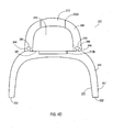
- FIG. 4D depicts a cross-sectional view of exemplary air channel containing member 202 as viewed within plane B-B and along line E-E as shown in FIG. 4 .
- exemplary air channel containing member 202 comprises upper foam member 240 comprising female attachment members 244 along lower section 248, and male attachment members 245 along upper section 247 lower foam member 241.
- Female attachment members 244 and male attachment members 245 enable attachment of upper and lower foam members 240 and 241 respectively to be attached to one another without the use of an additional fastening material (e.g., an adhesive).
- an additional fastening material e.g., an adhesive
- other desirable attachment members having different configurations may be used, as well as additional fastening materials (e.g., an adhesive) if so desired.
- slot 212 for fan 213 extends across indentation section 212A of upper foam member 240, as well as indentation section 212B of lower foam member 241 .
- fan 213 fits snugly within slot 212 in an upright position to reduce fan vibration, movement, noise, or any combination thereof.
- fan 213 may extend across fits air channel 210 so as to cover all of the cross-sectional area of air channel 210 or any portion thereof.
- Exemplary air channel containing member 202 comprising upper foam member 240 and lower foam member 241 provides a lightweight air channel formed from foam suitable foam material.
- each of upper and lower foam members 240 and 241 comprise a molded closed cell polyurethane foam.
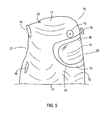
- exemplary surgical helmet 10 comprises a transparent face shield 11 along a front side 20 of helmet 10, and a hood 12 surrounding an outer periphery 13 of transparent face shield 11 and extending over and downward from a frame of helmet 10 (e.g., frame 30 shown in FIG. 10 below).
- exemplary surgical helmet 10 further comprises knob 14 that can be used to adjust the dimensions of the frame so as to better fit onto the head of a user.
- Knob 14 can be used to adjust a length (i.e., a first dimension extending from front side 20 to rear side 21) and a width of the frame (i.e., a dimension extending perpendicular to the first dimension, e.g., across transparent face shield 11).
- exemplary surgical helmet 10 further comprises damper knob 15, which can be used to adjust a damper positioned within a vicinity of an air outlet into the helmet. (See, for example, damper 72 in FIG. 9 , which is shown in an "up” position, but can be rotated into a “down” position away from wall 73 of frame component 33, in the direction as indicated by the arrow "D", to block air flow coming out of air outlet 28.)
- Exemplary helmet 10 further comprises an air channel containing member comprising an air channel extending along upper region 17 of helmet 10 and having at least one air inlet (e.g., air inlet 22 shown in FIG. 6 ) and at least one air outlet (e.g., air outlet 28 shown in FIG. 8 ), wherein the at least one air outlet is positioned so as to provide air to a space 60 bound by an inner surface of transparent face shield 11.
- a fan e.g., fan 27 shown in FIG. 8 below
- exemplary hood 12 of exemplary helmet 10 comprises (i) at least one hood air inlet 16 located within a periphery of hood 12 and aligned with the at least one air inlet (e.g., air inlet 22 shown in FIG. 6 ) of the air channel, and (ii) at least one hood air outlet 18 located within a periphery of hood 12.
- Hood air inlet 16 and hood air outlet 18 are operatively adapted to provide air flow through helmet 10 so as to decrease an amount of carbon dioxide buildup within helmet 10.
- hood air inlet(s) 16 and hood air outlet(s) 18 are positioned along a rear side 21 of helmet 10 opposite transparent face shield 11 (see, for example, FIG. 6 ); however, it should be understood that hood air inlet(s) 16 and hood air outlet(s) 18 may be positioned along any location of helmet 10 as long as hood air inlet(s) 16 and hood air outlet(s) 18 provide air flow through helmet 10 so as to decrease an amount of carbon dioxide buildup within helmet 10.
- FIG. 6 provides a rear view of exemplary helmet 10.
- exemplary hood 12 of exemplary helmet 10 comprises (i) a single hood air inlet 16 located within a periphery of hood 12, and (ii) two substantially similar hood air outlets 18 and 19 located within a periphery of hood 12, below hood air inlet 16, and positioned side-by-side along a neck region of hood 12.
- hood air inlet 16 is located within a periphery of the hood and aligned with air inlet 22 of air channel 25.
- Hood air outlets 18 and 19 are located within a periphery of the hood, and positioned below hood air inlet 16.
- Exemplary hood 12 extends below dashed line L-L to lower edge 24 of hood 12.
- exemplary helmet 10 comprises a power switch 23 positioned along upper region 17 of helmet 10.
- Power switch 23 is operatively adapted to switch from an "off" position to an "on” position so as to supply power to the fan (e.g., fan 27 shown in FIG. 8 below) and turn off power to the fan.
- power switch 23 is provided in other locations such as a position along an upper periphery of transparent face shield 11 (see, for example, power switch 23 shown in FIG. 10 ).
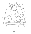
- FIG. 7 provides a rear close-up view of exemplary helmet 10.
- a first air filtration material 61 forms hood air inlet 16 of exemplary hood 12
- a second air filtration material 62 forms hood air outlets 18 and 19 of exemplary hood 12.
- First air filtration material 61 and second air filtration material 62 may comprise a variety of filtration materials such as the materials described above for the multiple pieces of additional hood material 110 and 111.
- each of first and second air filtration materials 61 and 62 comprises a spunbonded fabric, such as a nylon spunbonded fabric commercially available under the trade designation CEREX ® from Cerex Advanced Fabrics, Inc. (Pensacola, FL).
- hood 12 typically comprise a fluid/blood barrier material such as the fluid/blood barrier materials described above for first hood material 102.
- hood 12 comprises any breathable viral barrier (BVB) fabric commercially available from Ahlstrom Corporation (Alpharetta, GA), such as a BVB trilaminate polypropylene material.
- BVB breathable viral barrier
- FIG. 8 provides a view of exemplary helmet 10 of FIG. 5 when viewed from below helmet 10 (e.g., when viewed from position V shown in FIG. 5 ).
- exemplary helmet 10 comprises frame 30, which is operatively adapted to surround at least a portion of a person's head (not shown).
- Frame 30 typically comprises one or more frame components.
- frame 30 comprises the following frame components: adjustable frame component 31, which extends around at least a portion of a person's head and can be adjusted in length and width dimensions using knob 14 as described above; frame component 32, which at least partially surrounds transparent face shield 11 and attaches transparent face shield 11 to other helmet components; frame component 33, which extends along a front side 20 of exemplary helmet 10 and connects adjustable frame component 31 to frame component 32; knob extension member 37 extending along a portion of frame component 33 and being rotatably connected to knob 14; and frame component 34, which extends from a first location 65 along adjustable frame component 31 to a second location 66 along adjustable frame component 31 and is operatively adapted to conform to an outer contour of a person's head.
- exemplary helmet 10 may further comprise pads 35 positioned along one or more of the above-described frame components. As shown in FIG. 8 , exemplary helmet 10 comprises multiple pads 35 positioned along adjustable frame component 31 and a single pad 35 positioned along frame component 34.
- FIG. 8 provides a view of a battery pack 26 that is present in some helmets of the present invention.
- exemplary battery pack 26 is positioned along opposite sides of air channel 25. Electrical wiring (not shown) connects battery pack 26 to fan 27 and power switch 23 (shown in FIGS. 6 and 10 ).
- battery pack 26 may be located along any portion of frame 30. Desirably, as shown in FIGS. 8-10 , battery pack 26 is located above a lower edge of the transparent face shield, more desirably, above an upper portion of the transparent face shield and along one or both sides of air channel 25.
- FIG. 9 provides a close-up view of various helmet components within exemplary helmet 10.
- exemplary helmet 10 comprises air channel 25 extending between air inlet 22 and air outlet 28.
- Battery pack 26 is positioned along opposite sides of air channel 25.
- Electrical wiring 39 connects battery pack 26 to fan 27 and power switch 23 (shown in FIGS. 6 and 10 ).
- fan 27 is positioned within air channel 25 in the vicinity of air outlet 28.
- fan 27 may be positioned at any location within air channel 25 or at air inlet 22.
- Damper 72 is positioned adjacent wall 73 of frame component 33 in an "up” position, but can be rotated into a “down” position away from wall 73 and over air outlet 28 to block and/or redirect air flow through helmet 10.
- the degree of air blockage and air flow direction can be controlled by rotating knob 15 as discussed above.
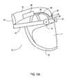
- FIG. 10A provides a side view of exemplary helmet, 10 of FIG. 5 when hood 12 is removed.
- exemplary helmet 10 comprises adjustable frame component 31 dimensioned so as to extend around at least a portion of a person's head; knobs 14 and 15, which are operatively adapted to adjust dimensions of adjustable frame component 31 and air flow through the helmet respectively; frame component 32 partially surrounding transparent face shield 11; frame component 34, which is operatively adapted to conform to an outer contour of a person's head; battery pack 26; fan 27; air channel 25; air inlet 22; air outlet 28; electrical wiring 40 connecting battery pack 26 to fan 27; and power switch 23.
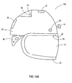
- FIG. 10B provides a side view of another exemplary helmet 10 without a hood component.
- exemplary helmet 100 comprises molded helmet component 78; knob 14, which is operatively adapted to adjust dimensions of a frame component (not shown but similar to adjustable frame component 31 shown in FIG.
- 10A extending around at least a portion of a person's head; frame component 32 partially surrounding transparent face shield 11; frame component 34, which is operatively adapted to conform to an outer contour of a person's head; battery pack 26; fan 27; air channel 25; air inlet 22; air outlet 28; electrical wiring connecting battery pack 26 to fan 27 (not shown, but typically within or along an inner surface of helmet component 78); and power switch/knob 23, which is operatively adapted to provide electricity to the fan and adjust the fan speed (i.e., air flow through the helmet).
- fan 27 can be positioned near air inlet 22 of air channel 25. Further, battery pack 26 can be positioned along a rear outer surface of helmet component 78.
- power switch/knob 23 is shown as a single switch/knob on exemplary helmet 100, it should be understood that a separate on/off switch and a separate air speed control knob could be present on exemplary helmet 100.
- multiple air inlets 22 and/or air outlets 28 could be utilized on exemplary helmet 100 to provide air flow through exemplary helmet 100. Further, one or more air inlets 22 and/or air outlets 28 can be positioned on exemplary helmet 100 in any desired locations so as to provide air flow through exemplary helmet 100.
- any of the above-described helmets are sterilized prior to use.
- a sterile field must be maintained around a surgical procedure site. Consequently, a surgical helmet used during such a surgical procedure must be sterilized prior to use.
- the helmets of the present invention are disposable. However, in some cases, the helmets of the present invention may be reusable. When reused, the helmet may need to be subjected to a cleaning procedure and/or sterilization procedure prior to reuse.
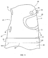
- exemplary surgical outfit 70 comprises exemplary surgical helmet 10 (or exemplary surgical helmet 200 in combination with exemplary surgical helmet cover assembly 100) in combination with surgical gown 50.
- Surgical gown 50 is sized so as to extend from a neck region of a user to a waist region of the user or below.
- Hood 12 of surgical helmet 10 (or hood 101 of exemplary surgical helmet cover assembly 100) is sized so as to extend below the neck region of the user.
- a lower portion 120 of hood 12 (outlined with dash line M-M) is tucked within an upper portion 52 of surgical gown 50.
- the at least one air outlet 18 when at least one air outlet 18 is present in hood 12 (or hood 101 of exemplary surgical helmet cover assembly 100), the at least one air outlet 18 is positioned above upper edge 51 of surgical gown 50. In such a configuration, upper portion 52 of surgical gown 50 effectively blocks air flow into surgical gown 50 and out through the at least one air outlet 18.
- surgical helmets 10 and 200 as shown in FIGS. 1-7 are only two exemplary surgical helmets of the present invention.
- exemplary surgical helmets 10 and 200 including, but not limited to, increasing the number of hood air inlet(s) 16 (or hood air inlet(s) 104) and/or the number of hood air outlets 18 and 19 (or hood air outlet(s) 105); increasing or decreasing the size of one or more components (e.g., transparent face shield 11 and/or hood air inlet(s) 16 and/or hood air outlets 18 and 19) relative to other components (e.g., hood 12); and rearranging one or more components of exemplary helmets 10 and 200 (e.g., changing the position of fan 27 to a position closer to air inlet 22 and/or changing the position of hood air outlets 18 and 19 so as to be closer to transparent face shield 11 and/or further away from hood air inlet(s) 16).
- surgical helmets of the present invention comprise from one to about five hood air inlet(s) 16 (or hood air inlet(s) 104), from one to about five hood air outlets 18 and 19 (or hood air outlet(s) 105), a single fan 27 (or fan 213), and a single air channel 25 (or air channel 210); however, surgical helmets of the present invention could comprise, for example, multiple fans and/or multiple air channels.
- helmet components including, but not limited to, adjustable frame component 31, frame component 32, frame component 33, frame component 34, frame component 201, knob extension member 37, knobs 14 and 15, air channel containing member 25 or 202, and transparent face shield 11 or 206, may be formed from any thermoformable material including, but not limited to, polymeric materials, metallic materials, or a combination thereof.
- the thermoformable materials can be molded or shaped using any conventional molding technique.
- the above-mentioned helmet components are formed from polymeric materials such as polyolefins (e.g., polyethylene, polypropylene, and olefin copolymers), polyurethanes, acrylonitrile-butadiene-styrene (ABS) copolymers, polyesters, polyethylene terephthalate glycol (PETG), polyamides, etc.
- polyolefins e.g., polyethylene, polypropylene, and olefin copolymers
- ABS acrylonitrile-butadiene-styrene copolymers
- polyesters e.g., polyethylene terephthalate glycol (PETG), polyamides, etc.
- PETG polyethylene terephthalate glycol
- Any films or film-like components including, but not limited to, adjustable frame component 31, frame component 34 and frame component 201 may be forming via any film-forming process including, but not limited to, a film extrusion process, a film-blowing process, etc.
- Fiber-containing helmet components such as hood 12 or hood 101, first and second air filtration materials 61 and 62, and multiple pieces of additional hood material 110 and 111 may be formed using conventional web-forming processes including, but not limited to, meltblowing processes, spunbonding processes, spunlacing processes, hydroentangling processes, carding processes, needlepunching processes, etc.
- the fiber-containing helmet components are formed from polymeric materials such as polyolefins (e.g., polyethylene, polypropylene, and olefin copolymers), nylon, acrylonitrile-butadiene-styrene (ABS) copolymers, etc.
- the hood is formed from an Ahlstrom Corporation BVB Material (e.g., trilaminate polypropylene material) and is thermally bonded to an outer periphery of a transparent face shield formed from PETG using a conventional thermal-bonding apparatus (e.g., an ultrasound welder).
- Ahlstrom Corporation BVB Material e.g., trilaminate polypropylene material
- a conventional thermal-bonding apparatus e.g., an ultrasound welder
- the surgical helmets and helmet components of the present invention are formed from the following materials: a closed cell polyurethane foam molded helmet component (e.g., helmet component 78 and upper and lower foam members 240 and 241); frame components (e.g., frame component 201 shown in FIG. 4 and adjustable frame component 31 shown in FIG.
- a closed cell polyurethane foam molded helmet component e.g., helmet component 78 and upper and lower foam members 240 and 241
- frame components e.g., frame component 201 shown in FIG. 4 and adjustable frame component 31 shown in FIG.
- a transparent face shield e.g., transparent face shield 11 or 106
- PETG PETG
- a frame component extending around the transparent face shield, when present, e.g., frame component 32
- head band material in the form of VELCRO ® brand terry cloth
- batteries - 4 AAA Alkaline batteries and air inlet and outlet material formed from CEREX ® nylon spunbonded fabric.
- the present invention is directed to a method of reducing an amount of carbon dioxide within a surgical outfit during use.
- the method comprises (A) providing a surgical outfit comprising (1) a helmet comprising (i) a frame operatively adapted to surround at least a portion of a person's head; (ii) a transparent face shield attached to the frame and positioned along a front side of the helmet; (iii) an air channel having at least one air inlet and at least one air outlet, the at least one air outlet being positioned so as to provide air to a space bound by an inner surface of the transparent face shield; and (iv) a fan in fluid communication with the air channel, the fan being operatively adapted to move air through the air channel; and (2) a hood or surgical gown surrounding the transparent face shield and extending over and downward from the frame, the hood or surgical gown comprising (i) at least one air inlet located within a periphery of the hood or surgical gown and aligned with the at least one air inlet of the air
- the method of reducing an amount of carbon dioxide within a surgical outfit comprises using the above-described exemplary surgical helmet 200 in combination with exemplary surgical helmet cover assembly 100 and a surgical gown.
- exemplary surgical helmet 200 in combination with exemplary surgical helmet cover assembly 100 provides controlled air flow, as well as controlled directional air flow through the surgical outfit.
- a sufficient volume of air and an essentially one-way direction of air flow (e.g., from hood air inlet 104 to at least one air channel inlet 203, through air channel 210, out of at least one air channel outlet 204 into a region of surgical helmet 200 bound by transparent face shield 206, along a wearer's neck line, and out of surgical helmet 200 through at least one hood air outlet 105 in a rear portion of surgical helmet 200) through the exemplary surgical helmet 200 and exemplary surgical helmet cover assembly 100 enables a significant reduction in carbon dioxide buildup within a surgical outfit.
- the method of reducing an amount of carbon dioxide within a surgical outfit, during use results in a carbon dioxide level of less than about 5000 ppm, more desirably, less than about 4000 ppm, even more desirably, less than about 3500 ppm, and even more desirably, less than about 3000 ppm (or less than about 2500 ppm, or less than about 2000 ppm, or less than about 1800 ppm).
- the surgical outfit of the present invention also improves air flow through the surgical outfit.
- air flow through a surgical outfit without at least one hood air outlet may be in the range of about 0.071 to about 0.096 cubic meters per minute (cmm) (2.5 to about 3.4 cubic feet per minute (cfm)), while air flow through a surgical outfit of the present invention with at least one hood air outlet can be in the range of about 0.110 to about 0.156 cmm (3.9 to about 5.5 cfm), an increase in air flow of as much as 120%.
- the above-described methods may further comprise one or more of the following steps: sterilizing the helmet prior to use, removing the helmet from a packaging material, adjusting the helmet frame to fit snugly on the surgeon's head, checking the power supply to insure the fan is operational, combining the helmet with other pieces of protective clothing, tucking a portion of the hood of the helmet within a surgical gown, and turning on the power supply for the fan.
Landscapes
- Health & Medical Sciences (AREA)
- General Health & Medical Sciences (AREA)
- Business, Economics & Management (AREA)
- Engineering & Computer Science (AREA)
- Textile Engineering (AREA)
- Toxicology (AREA)
- Physical Education & Sports Medicine (AREA)
- Emergency Management (AREA)
- Helmets And Other Head Coverings (AREA)
- Professional, Industrial, Or Sporting Protective Garments (AREA)
- Respiratory Apparatuses And Protective Means (AREA)
- Paints Or Removers (AREA)
- Materials For Medical Uses (AREA)
Abstract
Description
- This application is being filed as a PCT International Patent Application in the name of Microtek Medical, Inc., a U.S. corporation, claiming priority to
U.S. Patent Application Serial No. 11/710,699 filed on 26 February 2007 - The present invention relates generally to surgical helmets and surgical helmet components suitable for use in an operating room setting, methods of making surgical helmets and surgical helmet components, and methods of using surgical helmets and surgical helmet components, for example, in an operating room setting.
- A variety of disposable and reusable surgical helmets are used in operating rooms. Helmets are used to protect and/or cover a surgeon or other operating room personnel such as during a surgical procedure. During surgical procedures, it is important for a helmet to provide a barrier between the surgeon (or other operating room personnel) and the patient so as to protect the surgeon (or other operating room personnel) from exposure to body fluids and any other contaminants. Consequently, there is a tendency to for helmets and helmet components to be formed from barrier materials without additional considerations such as carbon dioxide build-up within the helmet during a surgical procedure.
- Recent studies have shown that carbon dioxide build-up within surgical helmets is an ongoing problem with currently available surgical helmets. Carbon dioxide build-up results from poor air flow through a given surgical helmet due to one or more factors including, but not limited to, poor air flow due to the use of a fan that does not produce sufficient air flow through the helmet, poor air flow due to uncontrolled air flow through the helmet (e.g., conflicting air flow directions), and poor helmet design due to the absence of air outlets in the surgical helmet. The combination of carbon dioxide build-up and stress due to the overall weight of currently available surgical helmets continue to be important factors in the design of new surgical helmets and helmet components. Efforts continue in the design of surgical helmets and helmet components to further enhance the properties (e.g., barrier properties, as well as air flow properties) and characteristics (e.g., comfort and overall weight) of surgical helmets and helmet components.
-
US 2003/0101505 A1 provides a head gear apparatus that moves air to cool a caregiver's head. The head gear apparatus includes a helmet and has a shell configured to rest upon the head of a user and a fan housing movably coupled to the shell. A fan is positioned to lie within the fan housing and moves with the fan housing relative to the shell and a garment selectively coupled to the helmet. The garment includes a face shield. -
US 6,374,823 B1 discloses a protective structure for use in a surgical environment including a face shield formed as a transparent tube to extend around the wearer's head and a cloth head covering extending above and around the face shield, with a viewing aperture being formed in the head covering to extend in front of the wearer's face, and with the head covering being attached to the face shield around the viewing aperture. A support structure extends from a rear portion of the face shield to a front portion thereof, forming an air channel through which air is moved by an internal fan between an air inlet aperture in the head covering at the rear of the support structure and an air outlet at the front of the support structure above the wearer's face. - There is a need in the art for surgical helmets and helmet components that (i) are suitable for use in an operating room setting, (ii) provide superior barrier protection to a surgeon (or other operating room personnel) during a surgical procedure, (iii) provide a desired degree of air flow and controlled directional air flow through the surgical helmet or helmet component so as to minimize the potential for carbon dioxide buildup within the helmet, (iv) are designed to be easily operational, (v) are designed without a separate battery pack and wires for connect the separate battery pack to the fan of the helmet, (vi) are relatively lightweight to reduce stress on the wearer, or (vii) any combination of items (i) to (vi).
- The present invention is directed to helmets and helmet components suitable for use in an operating room setting, an emergency room setting, a hospital setting, or a lab. The helmets and helmet components of the present invention provide one or more of the following features: (i) superior barrier protection to a surgeon (or other operating room personnel) during a surgical procedure, (ii) a desired degree of air flow and controlled directional air flow through the helmet so as to minimize the potential for carbon dioxide buildup within the helmet, (iii) a desired minimal helmet weight, and (iv) an optional integrated battery pack positioned within the helmet.
- According to one exemplary embodiment of the present invention, a surgical helmet component is disclosed, wherein the helmet component comprises a surgical helmet cover assembly comprising a hood sized to extend over a surgical helmet, the hood comprising a first hood material having (i) a face shield aperture completely surrounded by the first hood material, (ii) at least one hood air inlet completely surrounded by the first hood material, (iii) at least one hood air outlet completely surrounded by the first hood material, and (iv) a hood opening completely surrounded by the first hood material, the hood opening being sized so that the hood can be positioned over and onto a surgical helmet; a transparent face shield positioned over the face shield aperture and bonded to the fist hood material along an outer periphery of the face shield aperture so as to form a sterile barrier along the outer periphery between an interior volume of the hood and an exterior surface of the hood; characterised in that it further comprises multiple pieces of additional hood material positioned over the at least one hood air inlet and the at least one hood air outlet, wherein the multiple pieces of additional hood material (i) are bonded to the first hood material along an outer periphery of each of the at least one hood air inlet and the at least one hood air outlet, and (ii) have an air flow permeability greater than the first hood material. The surgical helmet cover assembly is typically disposable, and may be used with disposable or reuseable surgical helmets.
- According to a further exemplary embodiment of the present invention, a surgical helmet is disclosed, wherein the helmet comprises a frame operatively adapted to surround at least a portion of a person's head; a transparent face shield attached to the frame and positioned along a front side of the helmet; an air channel having at least one air channel inlet and at least one air channel outlet, the at least one air channel outlet being positioned so as to provide air to a space bound by an inner surface of the transparent face shield; a fan in fluid communication with the air channel, the fan being operatively adapted to move air through the air channel; a hood comprising a first hood material having (i) a face shield aperture completely surrounded by the first hood material and sized so that an outer periphery of the face shield aperture surrounds the transparent face shield, (ii) at least one hood air inlet completely surrounded by the first hood material and positioned to align with the at least one air channel inlet, (iii) at least one hood air outlet completely surrounded by the first hood material and positioned on a rear portion of the hood opposite the transparent face shield, and (iv) a hood opening completely surrounded by the first hood material, the hood opening sized so that the hood can be positioned over and onto the frame, the air channel and the fan; characterized in that it further comprises multiple pieces of additional hood material positioned over the at least one hood air inlet and the at least one hood air outlet, wherein the multiple pieces of additional hood material (i) are bonded to the first hood material along an outer periphery of each of the at least one hood air inlet and the at least one hood air outlet, and (ii) have an air flow permeability greater than the first hood material.
- The present invention is also directed to a surgical outfit comprising at least one surgical helmet.
- The present invention is even further directed to methods of reducing an amount of carbon dioxide within a surgical outfit during use. In one exemplary embodiment, the method comprises providing a surgical outfit of the present invention (such as the above-described surgical outfit or any surgical outfit described below), and cutting on the fan to provide an air flow path through at least one hood air inlet in a helmet, to at least one air channel inlet, through an air channel, out of at least one air channel outlet into a region of the helmet bound by a transparent face shield, and out of the helmet through at least one hood air outlet. The surgical outfit of the present invention is capable of reducing an amount of carbon dioxide within the surgical outfit, during use, to below about 2500 ppm, and even below about 1800 ppm.
- These and other features and advantages of the present invention will become apparent after a review of the following detailed description of the disclosed embodiments and the appended claims.
- The present invention is further described with reference to the appended figures, wherein:
-
FIG. 1 depicts a side view of an exemplary surgical helmet cover assembly of the present invention; -
FIG. 2A depicts a frontal view of the exemplary surgical helmet cover assembly shown inFIG. 1 ; -
FIG. 2B depicts a rear view of the exemplary surgical helmet cover assembly shown inFIG. 1 ; -
FIG. 3 depicts a cross-sectional view of the exemplary surgical helmet cover assembly ofFIG. 1 as viewed perpendicularly to plane A-A shown inFIG. 1 ; -
FIG. 4 depicts a side view of an exemplary surgical helmet of the present invention; -
FIG. 4A depicts a top view of the exemplary surgical helmet shown inFIG. 4 as viewed from above the exemplary surgical helmet; -
FIG. 4B depicts a cross-sectional view of the exemplary surgical helmet shown inFIG. 4 as viewed perpendicularly to plane B-B shown inFIG. 4 ; -
FIG. 4C depicts a close-up view of the exemplary surgical helmet shown inFIG. 4 when viewed from below the helmet; -
FIG. 4D depicts a cross-sectional view of the exemplary surgical helmet shown inFIG. 4 as viewed within plane B-B shown inFIG. 4 ; -
FIG. 5 depicts a side view of an exemplary helmet of the present invention; -
FIG. 6 depicts a rear view of the exemplary helmet ofFIG. 5 ; -
FIG. 7 depicts a close-up rear view of the exemplary helmet ofFIG. 5 ; -
FIG. 8 depicts a view of the exemplary helmet ofFIG. 5 when viewed from below the helmet; -
FIG. 9 depicts a close-up view of the frame, air channel, battery pack, and fan of the exemplary helmet ofFIG. 5 when viewed from below the helmet; -
FIG. 10A depicts a side view of the exemplary helmet ofFIG. 5 when the hood is removed; -
FIG. 10B depicts a side view of another exemplary helmet shown without a hood component; and -
FIG. 11 depicts an exemplary surgical outfit comprising the exemplary helmet ofFIG. 5 in combination with a surgical gown. - The present invention is directed to surgical helmets and surgical helmet components suitable for use in any environment in which a surgical helmet is typically used including, but not limited to, an operating room setting, an emergency room setting, a hospital setting, a lab, a clean room, etc. The surgical helmets and surgical helmet components of the present invention are particularly useful in providing a barrier between a surgeon and a surgical site of a patient.
- In one exemplary embodiment of the present invention, the present invention is directed to a surgical helmet cover assembly comprising a hood sized to extend over a surgical helmet, the hood comprising a first hood material having (i) a face shield aperture completely surrounded by the first hood material, (ii) at least one hood air inlet completely surrounded by the first hood material, (iii) at least one hood air outlet completely surrounded by the first hood material, and (iv) a hood opening completely surrounded by the first hood material, the hood opening being sized so that the hood can be positioned over and onto a surgical helmet; a transparent face shield positioned over the face shield aperture and bonded to the first hood material along an outer periphery of the face shield aperture so as to form a sterile barrier along the outer periphery between an interior volume of the hood and an exterior surface of the hood; and multiple pieces of additional hood material positioned over the at least one hood air inlet and the at least one hood air outlet, wherein the multiple pieces of additional hood material (i) are bonded to the first hood material along an outer periphery of each of the at least one hood air inlet and the at least one hood air outlet, and (ii) have an air flow permeability greater than the first hood material. An exemplary surgical helmet cover assembly is shown in
FIG. 1 . - As shown in
FIG. 1 , exemplary surgicalhelmet cover assembly 100 compriseshood 101 sized to extend over a surgical helmet (not shown), whereinhood 101 comprisesfirst hood material 102 having (i) aface shield aperture 103 completely surrounded byfirst hood material 102, (ii) at least onehood air inlet 104 completely surrounded byfirst hood material 102, (iii) at least onehood air outlet 105 completely surrounded byfirst hood material 102, and (iv) a hood opening 136 completely surrounded byfirst hood material 102. Hood opening 136 is sized so thathood opening 136 can be positioned over and onto a surgical helmet (not shown). Exemplary surgicalhelmet cover assembly 100 further comprises atransparent face shield 106 positioned overface shield aperture 103 and bonded tofirst hood material 102 along anouter periphery 107 offace shield aperture 103 so as to form a sterile barrier alongouter periphery 107 between an interior volume (e.g., interior volume 108 shown inFIG. 3 ) ofhood 101 and anexterior surface 109 ofhood 101. Exemplary surgicalhelmet cover assembly 100 further comprises multiple pieces ofadditional hood material hood air inlet 104 and the at least onehood air outlet 105 respectively, wherein each of the multiple pieces ofadditional hood material 110 and 111 (i) are bonded tofirst hood material 102 along anouter periphery hood air inlet 104 and the at least onehood air outlet 105 respectively, and (ii) have an air flow permeability greater thanfirst hood material 102. - As shown in
FIG. 1 ,hood 101 of exemplary surgicalhelmet cover assembly 100 may further comprise a resealable fanswitch knob opening 124 completely surrounded byfirst hood material 102. When present, resealable fan switch knob opening 124 (i) is sized so that a fan switch knob of a surgical helmet (see, for example,fan switch knob 23 of exemplarysurgical helmet 10 shown inFIG. 10B ) can fit therethrough, and (ii) is positioned along anouter surface 140 ofhood 101, desirably, above alower edge 125 oftransparent face shield 106, and more desirably, along an outer surface ofhood 101 abovetransparent face shield 106. -
FIG. 2A depicts a frontal view of exemplary surgicalhelmet cover assembly 100 shown inFIG. 1 . As shown inFIG. 2A ,transparent face shield 106 is positioned along afront side 114 ofhood 101 overface shield aperture 103. Further,transparent face shield 106 is completely surrounded byfirst hood material 102. As shown inFIG. 2A ,hood 101 may further comprises a resealable frameadjustment knob opening 121 completely surrounded byfirst hood material 102, wherein resealable frame adjustment knob opening 121 (i) is sized so that a frame adjustment knob of a surgical helmet (see, for example,frame adjustment knob 14 of exemplarysurgical helmet 10 shown inFIG. 9 ) can fit therethrough, and (ii) is positioned alongfront side 114 ofhood 101 and abovetransparent face shield 106. When exemplary surgicalhelmet cover assembly 100 is used in combination with a reuseable surgical helmet,hood 101 of exemplary surgicalhelmet cover assembly 100 does not have to comprise resealable frameadjustment knob opening 121 given that surgical helmet/frame adjustments are typically made on the helmet prior to attachment of exemplary surgicalhelmet cover assembly 100 to the surgical helmet. -
Hood 101 of exemplary surgicalhelmet cover assembly 100 typically comprises a singlehood air inlet 104 positioned along an upperrear portion 115 ofhood 101, and one or morehood air outlets 105 positioned along arear side 116 ofhood 101 below singlehood air inlet 104 and opposite transparent face shield 106 (e.g., in a neck region of the wearer). In one desired embodiment,hood 101 comprises two separatehood air outlets 105 positioned side-by-side alongrear side 115 ofhood 101 below singlehood air inlet 104 and opposite transparent face shield 106 (i.e., instead of a singlehood air outlet 105 as shown inFIG. 2B , twohood air outlets 105 would be present in a neck region of the wearer similar tohood air outlets 62 shown inFIG. 7 ). - As shown in
FIG. 2B ,hood 101 may further comprise apocket 117 positioned alongrear side 116 ofhood 101, whereinpocket 117 is sized so as to accept a battery pack (not shown) therein. When present,pocket 117 may be positioned along any portion of anouter surface 140 ofhood 101, althoughpocket 117 is desirably positioned below at least onehood air inlet 104 and below at least onehood air outlet 105 as shown inFIG. 2B . Although not shown inFIG. 2B ,hood 101 may further comprise a slot infirst hood material 102, wherein the slot is desirably positioned withinpocket 117 and sized so that a battery pack connector (not shown) can extend through the slot. In some embodiments,pocket 117 may be used to store a supplemental battery, with a primary battery being positioned within a frame component or air channel containing member (e.g., foam member) of a surgical helmet as described further below. -
FIG. 3 depicts a cross-sectional view of exemplary surgicalhelmet cover assembly 100 ofFIG. 1 as viewed perpendicularly to plane A-A shown inFIG. 1 . As shown inFIG. 3 , exemplary surgicalhelmet cover assembly 100 may further comprise one ormore attachment members 118 positioned along (i) aninner surface 119 ofhood 101, (ii) aninner surface 120 oftransparent face shield 106, or (iii) both (i) and (ii). One ormore attachment members 118 are operatively adapted to connect exemplary surgicalhelmet cover assembly 100 to a surgical helmet (for example, exemplarysurgical helmet 200 shown inFIG. 4 ).Attachment members 118 may comprise a variety of materials including, but not limited to, hook and/or loop material, magnets, adhesive tape, etc. - As shown in
FIG. 3 , exemplary surgicalhelmet cover assembly 100 may further comprise one or more adjustableface shield spacers 127 positioned along aninner surface 120 oftransparent face shield 106. When present, the one or more adjustableface shield spacers 127 are operatively adapted to alter a line of curvature extending from one side of transparent face shield 106 (i.e.,side 128 shown inFIG. 2A ) to an opposite side of transparent face shield 106 (i.e.,side 129 shown inFIG. 2A ). Any member (e.g., a screw-like member) capable of adjusting a distance betweentransparent face shield 106 and a surgical helmet component, for example, as a frame or air channel containing member (described further below), may be used for each adjustableface shield spacer 127. Alteration of the line of curvature oftransparent face shield 106 may help reduce an amount of glare when viewing a surgical site throughtransparent face shield 106. - First hood material 102 (and
pocket 117, when present) typically comprises a fluid/blood barrier material. The fluid/blood barrier material typically comprises a single layer of nonwoven fabric or a single layer of nonwoven fabric/film laminate having little or no air permeability. Typically, the fluid/blood barrier material has an air permeability (i.e., as measured using ASTM D737 test method) of less than about 17.1 cm3/min/cm2 of material (0.562 ft3/min/ft2 of material). In one desired embodiment, the fluid/blood barrier material comprises a breathable viral barrier (BVB) fabric commercially available from Ahlstrom Corporation (Alpharetta, GA), such as a BVB trilaminate polypropylene material having a basis weight of about 70 grams per square meter (gsm) and a thickness of about 0.35 millimeters (mm). - Multiple pieces of
additional hood material 110 and 111 (also referred to herein as "air filtration material") may comprise a variety of air filtration (i.e., air permeable) materials. Typically, each of multiple pieces ofadditional hood material additional hood material - Typically, each of multiple pieces of
additional hood material first hood material 102 typically comprises one of the above-mentioned fluid/blood barrier materials having a basis weight of greater than about 50 gsm) (more typically, from about 50 gsm to about 100 gsm, even more typically, from about 70 gsm to about 80 gsm) and a fabric thickness of greater than about 0.25 mm, typically, from about 0.35 mm to about 0.5 mm. - The above-described surgical helmet cover assemblies of the present invention are typically disposable, and may be used with disposable or reuseable surgical helmets of the present invention such as the surgical helmets described below. One exemplary surgical helmet of the present invention is shown in
FIG. 4 . - As shown in
FIG. 4 , exemplarysurgical helmet 200 of the present invention comprises aframe 201 operatively adapted to surround at least a portion of a person's head (not shown); an air channel containing member 202 (e.g., a foam member) having an air channel therein (see,air channel 210 inFIG. 4B ), wherein the air channel has at least oneair channel inlet 203 and at least oneair channel outlet 204, the at least oneair channel outlet 204 being positioned so as to provide air to a space bound by (i) the face of a wearer (not shown) and (ii) an inner surface of a transparent face shield (not shown) when present; and a fan (see,fan 213 inFIG. 4A ) in fluid communication with the air channel (not shown), the fan being operatively adapted to move air through the air channel of airchannel containing member 202. - As shown in
FIG. 4 , exemplarysurgical helmet 200 may further comprise aframe adjustment knob 205 that can be used to adjust the dimensions offrame 201 so as to better fit onto the head of a user (not shown).Knob 205 can be used to adjust a length (i.e., a first dimension extending fromfront side 206 to rear side 207) and a width of frame 201 (i.e., a dimension extending perpendicular to the first dimension, e.g., across a width of exemplary surgical helmet 200). Exemplarysurgical helmet 200 may further comprise afan adjustment knob 205 that can be used to (i) cut "on" or "off" the fan, (ii) change a speed of the fan, or (iii) both (i) and (ii). - Exemplary
surgical helmet 200 may further comprisefrontal pad 209 andrear pad 211 along opposite ends offrame 201 to provide additional comfort to a user (not shown). In addition, exemplarysurgical helmet 200 may further comprise one or moreadjustable helmet spacers 227, which, like adjustableface shield spacers 127 described above, are operatively adapted to alter a line of curvature extending from one side of a transparent face shield to an opposite side of transparent face shield so as to help reduce an amount of glare when viewing a surgical site through the transparent face shield. - Exemplary
surgical helmet 200 may be used in combination with a detachable or permanently attached surgical helmet cover assembly, such as exemplary surgicalhelmet cover assembly 100 discussed above. As shown inFIG. 4 , exemplarysurgical helmet 200 may comprise one ormore attachment members 218 that assist in attaching a surgical helmet cover assembly, such as exemplary surgicalhelmet cover assembly 100 discussed above, to exemplarysurgical helmet 200. For example,attachment members 118 of exemplary surgicalhelmet cover assembly 100 shown inFIG. 3 andattachment members 218 of exemplarysurgical helmet 200 may comprise, for example, hook and loop material, respectively, to aid in the attachment of exemplary surgicalhelmet cover assembly 100 to exemplarysurgical helmet 200. In other embodiments,attachment members -
FIG. 4A depicts a top view of exemplarysurgical helmet 200 shown inFIG. 4 as viewed from above exemplarysurgical helmet 200. As shown inFIG. 4A , airchannel containing member 202 has at least oneair channel inlet 203 positioned along an upperrear portion 214 of airchannel containing member 202, and afan 213 in fluid communication with the air channel (not shown).Fan 213 is positioned withinslot 212 and is operatively adapted to move air through the air channel of airchannel containing member 202 in a direction as shown by arrow A inFIG. 4A . As shown inFIG. 4A , airchannel containing member 202 may further comprise anindention 215 sized to house a primary battery pack (not shown) for supplying electricity tofan 213. -
FIG. 4B depicts a cross-sectional view of exemplarysurgical helmet 200 shown inFIG. 4 as viewed perpendicularly to plane B-B shown inFIG. 4 so as to showair channel 210. As shown inFIG. 4B ,air channel 210 of airchannel containing member 202 extends from at least oneair channel inlet 203 positioned along an upperrear portion 214 of airchannel containing member 202 toair channel outlet 204 positioned along afront portion 216 of airchannel containing member 202.Slot 212, which is sized so as to house fan 213 (not shown), desirably has a width slightly greater than a width ofair channel 210 and a height slightly greater than a height ofair channel 210, so thatfan 213 fits snugly withinslot 212 and does not move out ofslot 212 during operation. When airchannel containing member 202 comprises a foam member as discussed further below, slot 212 of airchannel containing member 202 also absorbs any undesirable vibration offan 213 positioned withinslot 212. In necessary, an additional piece of material (e.g., foam) (not shown) may be used to snugly positionfan 213 withinslot 212. - Although not shown in
FIG. 4B ,desirably fan 213 is in an upright position withinslot 212. In other words, desirably,fan 213 is positioned withinslot 212 ofair channel 210 so that fan blades offan 213 move in a plane that is substantially perpendicular to a direction of air flow through air channel 210 (i.e., in a plane substantially perpendicular to a direction of air flow as shown by arrow A). - As discussed further below, air
channel containing member 202 may further comprise one ormore openings 220 within airchannel containing member 202.Openings 220 may be present to further reduce an overall weight of airchannel containing member 202. Any number ofopenings 220 may be present within airchannel containing member 202 as long as airchannel containing member 202 maintains sufficient structural integrity for supporting the various components of the disclosed surgical helmets. - As shown
FIG. 4B , airchannel containing member 202 may compriseindentation 215 for housing a battery pack (not shown). Desirably, a battery pack (not shown) is positioned withinindentation 215 and attached to airchannel containing member 202 and/orframe 201 and positioned above a lower edge of a transparent face shield (not shown), wherein the battery pack is operatively adapted to supply electrical power tofan 213. As discussed above, a supplemental battery pack may be positioned within a pocket (e.g., pocket 117) along an outer surface of a hood (e.g., hood 101) used in combination with exemplarysurgical helmet 200. -
FIG. 4C depicts a close-up view of exemplarysurgical helmet 200 shown inFIG. 4 when viewed from below exemplarysurgical helmet 200. As shown inFIG. 4C , exemplarysurgical helmet 200 further comprisesstraps 221 extending from opposite sides offrame 201 and/or opposite sides of an inner surface 223 (or an outer surface 257) of airchannel containing member 202.Straps 221 help support exemplarysurgical helmet 200 on the head of a user (not shown). As discussed above,frame 201 along with frame adjustment knob 205 (not shown) may be used to adjust an overall length offrame loop 231 extending between points X and Y as shown inFIG. 4C . By turning frame adjustment knob 205 (not shown),loop length adjuster 251 either (1) moves portions of frame loop 231 (e.g., loop portions at points X and Y) toward one another to decrease an overall length offrame loop 231 or (2) moves portions of frame loop 231 (e.g., loop portions at points X and Y) away from one another to increase an overall length offrame loop 231. - In one exemplary embodiment, air
channel containing member 202 comprises a foam member. In this exemplary embodiment, airchannel containing member 202 may comprise anupper foam member 240 and alower foam member 241 attached to one another. As shownFIG. 4C ,upper foam member 240 havinglower edge 224 in combination withlower foam member 241 havinglower edge 222form air channel 210 positioned betweeninner surface 228 ofupper foam member 240 andinner surface 229 oflower foam member 241. - As shown
FIG. 4C ,lower foam member 241 is operatively adapted to surround at least a portion of a person's head (not shown). As discussed above, frame 201 (and portions thereof) may be attached tolower foam member 241 alonginner surface 223,outer surface 257,lower edge 222, or any combination thereof using mechanical fasteners or adhesives. Further, as discussed above,lower foam member 241 may comprise one or more openings/apertures 220 therein to reduce an overall weight oflower foam member 241. - In one exemplary embodiment,
upper foam member 240 andlower foam member 241 comprise attachment features that enableupper foam member 240 andlower foam member 241 to be attached to one another without the use of an additional fastening material. For example,upper foam member 240 andlower foam member 241 may snap together upon application of an attachment force. An example of such a configuration is shown inFIG. 4D . -
FIG. 4D depicts a cross-sectional view of exemplary airchannel containing member 202 as viewed within plane B-B and along line E-E as shown inFIG. 4 . As shown inFIG. 4D , exemplary airchannel containing member 202 comprisesupper foam member 240 comprisingfemale attachment members 244 alonglower section 248, andmale attachment members 245 alongupper section 247lower foam member 241.Female attachment members 244 andmale attachment members 245 enable attachment of upper andlower foam members - As shown in
FIG. 4D ,slot 212 for fan 213 (not shown) extends acrossindentation section 212A ofupper foam member 240, as well asindentation section 212B oflower foam member 241. As discussed above, desirably,fan 213 fits snugly withinslot 212 in an upright position to reduce fan vibration, movement, noise, or any combination thereof. Although shown as only covering a portion of a cross-sectional area ofair channel 210, it should be noted thatfan 213 may extend across fitsair channel 210 so as to cover all of the cross-sectional area ofair channel 210 or any portion thereof. - Exemplary air
channel containing member 202 comprisingupper foam member 240 andlower foam member 241 provides a lightweight air channel formed from foam suitable foam material. In one exemplary embodiment, each of upper andlower foam members - Another exemplary
surgical helmet 10 is shown inFIG. 5 . As shown inFIG. 5 , exemplarysurgical helmet 10 comprises atransparent face shield 11 along afront side 20 ofhelmet 10, and ahood 12 surrounding anouter periphery 13 oftransparent face shield 11 and extending over and downward from a frame of helmet 10 (e.g.,frame 30 shown inFIG. 10 below). Exemplarysurgical helmet 10 further comprisesknob 14 that can be used to adjust the dimensions of the frame so as to better fit onto the head of a user.Knob 14 can be used to adjust a length (i.e., a first dimension extending fromfront side 20 to rear side 21) and a width of the frame (i.e., a dimension extending perpendicular to the first dimension, e.g., across transparent face shield 11). Exemplarysurgical helmet 10 further comprisesdamper knob 15, which can be used to adjust a damper positioned within a vicinity of an air outlet into the helmet. (See, for example,damper 72 inFIG. 9 , which is shown in an "up" position, but can be rotated into a "down" position away fromwall 73 offrame component 33, in the direction as indicated by the arrow "D", to block air flow coming out ofair outlet 28.) -
Exemplary helmet 10 further comprises an air channel containing member comprising an air channel extending alongupper region 17 ofhelmet 10 and having at least one air inlet (e.g.,air inlet 22 shown inFIG. 6 ) and at least one air outlet (e.g.,air outlet 28 shown inFIG. 8 ), wherein the at least one air outlet is positioned so as to provide air to aspace 60 bound by an inner surface oftransparent face shield 11. A fan (e.g.,fan 27 shown inFIG. 8 below) is in fluid communication with the air channel, and is operatively adapted to move air through the air channel. - As shown in
FIG. 5 , in some desired embodiments of the present invention,exemplary hood 12 ofexemplary helmet 10 comprises (i) at least onehood air inlet 16 located within a periphery ofhood 12 and aligned with the at least one air inlet (e.g.,air inlet 22 shown inFIG. 6 ) of the air channel, and (ii) at least onehood air outlet 18 located within a periphery ofhood 12.Hood air inlet 16 andhood air outlet 18 are operatively adapted to provide air flow throughhelmet 10 so as to decrease an amount of carbon dioxide buildup withinhelmet 10. Desirably, hood air inlet(s) 16 and hood air outlet(s) 18 are positioned along arear side 21 ofhelmet 10 opposite transparent face shield 11 (see, for example,FIG. 6 ); however, it should be understood that hood air inlet(s) 16 and hood air outlet(s) 18 may be positioned along any location ofhelmet 10 as long as hood air inlet(s) 16 and hood air outlet(s) 18 provide air flow throughhelmet 10 so as to decrease an amount of carbon dioxide buildup withinhelmet 10. -
FIG. 6 provides a rear view ofexemplary helmet 10. As shown inFIG. 6 ,exemplary hood 12 ofexemplary helmet 10 comprises (i) a singlehood air inlet 16 located within a periphery ofhood 12, and (ii) two substantially similarhood air outlets hood 12, belowhood air inlet 16, and positioned side-by-side along a neck region ofhood 12. As shown inFIG. 6 ,hood air inlet 16 is located within a periphery of the hood and aligned withair inlet 22 ofair channel 25.Hood air outlets hood air inlet 16. In this exemplary embodiment, air entershelmet 10 at a position above a user's head, and exitshelmet 10 along a neck region of the user as designated by dashed line L-L.Exemplary hood 12 extends below dashed line L-L tolower edge 24 ofhood 12. - In the exemplary embodiment of
FIG. 6 ,exemplary helmet 10 comprises apower switch 23 positioned alongupper region 17 ofhelmet 10.Power switch 23 is operatively adapted to switch from an "off" position to an "on" position so as to supply power to the fan (e.g.,fan 27 shown inFIG. 8 below) and turn off power to the fan. In other exemplary embodiments,power switch 23 is provided in other locations such as a position along an upper periphery of transparent face shield 11 (see, for example,power switch 23 shown inFIG. 10 ). -
FIG. 7 provides a rear close-up view ofexemplary helmet 10. As shown inFIG. 7 , a firstair filtration material 61 formshood air inlet 16 ofexemplary hood 12, and a secondair filtration material 62 formshood air outlets exemplary hood 12. Firstair filtration material 61 and secondair filtration material 62 may comprise a variety of filtration materials such as the materials described above for the multiple pieces ofadditional hood material air filtration materials - The remaining portions of hood 12 (i.e., all of
hood 12 other thanhood air inlet 16 andhood air outlets 18 and 19) typically comprise a fluid/blood barrier material such as the fluid/blood barrier materials described above forfirst hood material 102. In one desired embodiment,hood 12 comprises any breathable viral barrier (BVB) fabric commercially available from Ahlstrom Corporation (Alpharetta, GA), such as a BVB trilaminate polypropylene material. -
FIG. 8 provides a view ofexemplary helmet 10 ofFIG. 5 when viewed from below helmet 10 (e.g., when viewed from position V shown inFIG. 5 ). As shown inFIG. 8 ,exemplary helmet 10 comprisesframe 30, which is operatively adapted to surround at least a portion of a person's head (not shown).Frame 30 typically comprises one or more frame components. Inexemplary helmet 10,frame 30 comprises the following frame components:adjustable frame component 31, which extends around at least a portion of a person's head and can be adjusted in length and widthdimensions using knob 14 as described above;frame component 32, which at least partially surroundstransparent face shield 11 and attachestransparent face shield 11 to other helmet components;frame component 33, which extends along afront side 20 ofexemplary helmet 10 and connectsadjustable frame component 31 to framecomponent 32;knob extension member 37 extending along a portion offrame component 33 and being rotatably connected toknob 14; andframe component 34, which extends from afirst location 65 alongadjustable frame component 31 to asecond location 66 alongadjustable frame component 31 and is operatively adapted to conform to an outer contour of a person's head. - As shown in
FIG. 8 ,exemplary helmet 10 may further comprisepads 35 positioned along one or more of the above-described frame components. As shown inFIG. 8 ,exemplary helmet 10 comprisesmultiple pads 35 positioned alongadjustable frame component 31 and asingle pad 35 positioned alongframe component 34. -
FIG. 8 provides a view of abattery pack 26 that is present in some helmets of the present invention. As shown inFIG. 8 ,exemplary battery pack 26 is positioned along opposite sides ofair channel 25. Electrical wiring (not shown) connectsbattery pack 26 to fan 27 and power switch 23 (shown inFIGS. 6 and10 ). Although shown on opposite sides ofair channel 25, it should be understood thatbattery pack 26 may be located along any portion offrame 30. Desirably, as shown inFIGS. 8-10 ,battery pack 26 is located above a lower edge of the transparent face shield, more desirably, above an upper portion of the transparent face shield and along one or both sides ofair channel 25. -
FIG. 9 provides a close-up view of various helmet components withinexemplary helmet 10. As shown inFIG. 9 ,exemplary helmet 10 comprisesair channel 25 extending betweenair inlet 22 andair outlet 28.Battery pack 26 is positioned along opposite sides ofair channel 25.Electrical wiring 39 connectsbattery pack 26 to fan 27 and power switch 23 (shown inFIGS. 6 and10 ). As shown inFIG. 9 ,fan 27 is positioned withinair channel 25 in the vicinity ofair outlet 28. However, it should be understood thatfan 27 may be positioned at any location withinair channel 25 or atair inlet 22.Damper 72 is positionedadjacent wall 73 offrame component 33 in an "up" position, but can be rotated into a "down" position away fromwall 73 and overair outlet 28 to block and/or redirect air flow throughhelmet 10. The degree of air blockage and air flow direction can be controlled by rotatingknob 15 as discussed above. -
FIG. 10A provides a side view of exemplary helmet, 10 ofFIG. 5 whenhood 12 is removed. As shown inFIG. 10A ,exemplary helmet 10 comprisesadjustable frame component 31 dimensioned so as to extend around at least a portion of a person's head; knobs 14 and 15, which are operatively adapted to adjust dimensions ofadjustable frame component 31 and air flow through the helmet respectively;frame component 32 partially surroundingtransparent face shield 11;frame component 34, which is operatively adapted to conform to an outer contour of a person's head;battery pack 26;fan 27;air channel 25;air inlet 22;air outlet 28;electrical wiring 40 connectingbattery pack 26 tofan 27; andpower switch 23. -
FIG. 10B provides a side view of anotherexemplary helmet 10 without a hood component. As shown inFIG. 10B ,exemplary helmet 100 comprises moldedhelmet component 78;knob 14, which is operatively adapted to adjust dimensions of a frame component (not shown but similar toadjustable frame component 31 shown inFIG. 10A ) extending around at least a portion of a person's head;frame component 32 partially surroundingtransparent face shield 11;frame component 34, which is operatively adapted to conform to an outer contour of a person's head;battery pack 26;fan 27;air channel 25;air inlet 22;air outlet 28; electrical wiring connectingbattery pack 26 to fan 27 (not shown, but typically within or along an inner surface of helmet component 78); and power switch/knob 23, which is operatively adapted to provide electricity to the fan and adjust the fan speed (i.e., air flow through the helmet). - As shown in FIG. 6B,
fan 27 can be positioned nearair inlet 22 ofair channel 25. Further,battery pack 26 can be positioned along a rear outer surface ofhelmet component 78. Although power switch/knob 23 is shown as a single switch/knob onexemplary helmet 100, it should be understood that a separate on/off switch and a separate air speed control knob could be present onexemplary helmet 100. As discussed above,multiple air inlets 22 and/orair outlets 28 could be utilized onexemplary helmet 100 to provide air flow throughexemplary helmet 100. Further, one ormore air inlets 22 and/orair outlets 28 can be positioned onexemplary helmet 100 in any desired locations so as to provide air flow throughexemplary helmet 100. - In one exemplary embodiment, any of the above-described helmets are sterilized prior to use. For example, in an operating room setting, a sterile field must be maintained around a surgical procedure site. Consequently, a surgical helmet used during such a surgical procedure must be sterilized prior to use.
- Typically, the helmets of the present invention are disposable. However, in some cases, the helmets of the present invention may be reusable. When reused, the helmet may need to be subjected to a cleaning procedure and/or sterilization procedure prior to reuse.
- The present invention is also directed to a surgical outfit comprising at least one helmet. An exemplary surgical outfit is shown in
FIG. 7 . As shown inFIG. 7 , exemplarysurgical outfit 70 comprises exemplary surgical helmet 10 (or exemplarysurgical helmet 200 in combination with exemplary surgical helmet cover assembly 100) in combination withsurgical gown 50.Surgical gown 50 is sized so as to extend from a neck region of a user to a waist region of the user or below.Hood 12 of surgical helmet 10 (orhood 101 of exemplary surgical helmet cover assembly 100) is sized so as to extend below the neck region of the user. In one desired configuration shown inFIG. 7 , alower portion 120 of hood 12 (outlined with dash line M-M) is tucked within anupper portion 52 ofsurgical gown 50. Desirably, when at least oneair outlet 18 is present in hood 12 (orhood 101 of exemplary surgical helmet cover assembly 100), the at least oneair outlet 18 is positioned aboveupper edge 51 ofsurgical gown 50. In such a configuration,upper portion 52 ofsurgical gown 50 effectively blocks air flow intosurgical gown 50 and out through the at least oneair outlet 18. - It should be noted that
surgical helmets FIGS. 1-7 are only two exemplary surgical helmets of the present invention. Various modifications could be made to exemplarysurgical helmets hood air outlets 18 and 19 (or hood air outlet(s) 105); increasing or decreasing the size of one or more components (e.g.,transparent face shield 11 and/or hood air inlet(s) 16 and/orhood air outlets 18 and 19) relative to other components (e.g., hood 12); and rearranging one or more components ofexemplary helmets 10 and 200 (e.g., changing the position offan 27 to a position closer toair inlet 22 and/or changing the position ofhood air outlets transparent face shield 11 and/or further away from hood air inlet(s) 16). - Typically, surgical helmets of the present invention comprise from one to about five hood air inlet(s) 16 (or hood air inlet(s) 104), from one to about five
hood air outlets 18 and 19 (or hood air outlet(s) 105), a single fan 27 (or fan 213), and a single air channel 25 (or air channel 210); however, surgical helmets of the present invention could comprise, for example, multiple fans and/or multiple air channels. - Any of the above-described individual components used to form the helmets and helmet components of the present invention may be formed using conventional methods. For example, helmet components including, but not limited to,
adjustable frame component 31,frame component 32,frame component 33,frame component 34,frame component 201,knob extension member 37, knobs 14 and 15, airchannel containing member transparent face shield - Any films or film-like components including, but not limited to,
adjustable frame component 31,frame component 34 andframe component 201 may be forming via any film-forming process including, but not limited to, a film extrusion process, a film-blowing process, etc. - Fiber-containing helmet components, such as
hood 12 orhood 101, first and secondair filtration materials additional hood material - Thermoformed parts, films and/or fabric layers may be joined to one another using any conventional bonding technique including, but not limited to, thermal bonding processes, adhesive bonding, mechanical bonding (e.g., hook and loop material), etc. In one exemplary embodiment of the present invention, the hood is formed from an Ahlstrom Corporation BVB Material (e.g., trilaminate polypropylene material) and is thermally bonded to an outer periphery of a transparent face shield formed from PETG using a conventional thermal-bonding apparatus (e.g., an ultrasound welder).
- In one desired embodiment, the surgical helmets and helmet components of the present invention are formed from the following materials: a closed cell polyurethane foam molded helmet component (e.g.,
helmet component 78 and upper andlower foam members 240 and 241); frame components (e.g.,frame component 201 shown inFIG. 4 andadjustable frame component 31 shown in FIG. 6A) formed from polyethylene; a transparent face shield (e.g.,transparent face shield 11 or 106) formed from PETG; a frame component extending around the transparent face shield, when present, (e.g., frame component 32) formed from polyvinyl chloride (PVC); head band material in the form of VELCRO® brand terry cloth; batteries - 4 AAA Alkaline batteries; and air inlet and outlet material formed from CEREX® nylon spunbonded fabric. - The present invention is directed to a method of reducing an amount of carbon dioxide within a surgical outfit during use. In this exemplary embodiment, the method comprises (A) providing a surgical outfit comprising (1) a helmet comprising (i) a frame operatively adapted to surround at least a portion of a person's head; (ii) a transparent face shield attached to the frame and positioned along a front side of the helmet; (iii) an air channel having at least one air inlet and at least one air outlet, the at least one air outlet being positioned so as to provide air to a space bound by an inner surface of the transparent face shield; and (iv) a fan in fluid communication with the air channel, the fan being operatively adapted to move air through the air channel; and (2) a hood or surgical gown surrounding the transparent face shield and extending over and downward from the frame, the hood or surgical gown comprising (i) at least one air inlet located within a periphery of the hood or surgical gown and aligned with the at least one air inlet of the air channel, and (ii) at least one air outlet located within a periphery of the hood or surgical gown; and (B) cutting on the fan to provide air flow along a path through the surgical outfit components in the following order: an air inlet in a surgical gown, at least one hood air inlet in a helmet, to at least one air inlet, through an air channel, out of at least one air outlet into a region of the helmet bound by a transparent face shield, out of the helmet through at least one hood air outlet, and out of the surgical gown through at least one air outlet in the surgical gown.
- Desirably, the method of reducing an amount of carbon dioxide within a surgical outfit comprises using the above-described exemplary
surgical helmet 200 in combination with exemplary surgicalhelmet cover assembly 100 and a surgical gown. As discussed above, exemplarysurgical helmet 200 in combination with exemplary surgicalhelmet cover assembly 100 provides controlled air flow, as well as controlled directional air flow through the surgical outfit. In other words, a sufficient volume of air and an essentially one-way direction of air flow (e.g., fromhood air inlet 104 to at least oneair channel inlet 203, throughair channel 210, out of at least oneair channel outlet 204 into a region ofsurgical helmet 200 bound bytransparent face shield 206, along a wearer's neck line, and out ofsurgical helmet 200 through at least onehood air outlet 105 in a rear portion of surgical helmet 200) through the exemplarysurgical helmet 200 and exemplary surgicalhelmet cover assembly 100 enables a significant reduction in carbon dioxide buildup within a surgical outfit. - The method of reducing an amount of carbon dioxide within a surgical outfit, during use, results in a carbon dioxide level of less than about 5000 ppm, more desirably, less than about 4000 ppm, even more desirably, less than about 3500 ppm, and even more desirably, less than about 3000 ppm (or less than about 2500 ppm, or less than about 2000 ppm, or less than about 1800 ppm).
- The surgical outfit of the present invention also improves air flow through the surgical outfit. For example, air flow through a surgical outfit without at least one hood air outlet may be in the range of about 0.071 to about 0.096 cubic meters per minute (cmm) (2.5 to about 3.4 cubic feet per minute (cfm)), while air flow through a surgical outfit of the present invention with at least one hood air outlet can be in the range of about 0.110 to about 0.156 cmm (3.9 to about 5.5 cfm), an increase in air flow of as much as 120%.
- The above-described methods may further comprise one or more of the following steps: sterilizing the helmet prior to use, removing the helmet from a packaging material, adjusting the helmet frame to fit snugly on the surgeon's head, checking the power supply to insure the fan is operational, combining the helmet with other pieces of protective clothing, tucking a portion of the hood of the helmet within a surgical gown, and turning on the power supply for the fan.
- While the specification has been described in detail with respect to specific embodiments thereof, it will be appreciated that those skilled in the art, upon attaining an understanding of the foregoing, may readily conceive of alterations to, variations of, and equivalents to these embodiments. Accordingly, the scope of the present invention should be assessed as that of the appended claims and any equivalents thereto.
Claims (16)
- A surgical helmet cover assembly (100) comprising: a hood (101) sized to extend over a surgical helmet, said hood (101) comprising a first hood material (102) having (i) a face shield aperture (103) completely surrounded by said first hood material (102), (ii) at least one hood air inlet (104) completely surrounded by said first hood material (102), (iii) at least one hood air outlet (105) completely surrounded by said first hood material (102), and (iv) a hood opening (136) completely surrounded by said first hood material (102), said hood opening (136) being sized so that said hood (101) can be positioned over and onto a surgical helmet; a transparent face shield (106) positioned over said face shield aperture (103) and bonded to said first hood material (102) along an outer periphery (107) of said face shield aperture (103) so as to form a sterile barrier along said outer periphery (107) between an interior volume (108) of said hood and an exterior surface (109) of said hood (101): characterised in that it further comprises multiple pieces of additional hood material (110 and 111) positioned over said at least one hood air inlet (104) and said at least one hood air outlet (105), wherein said multiple pieces of additional hood material (110 and 111) (i) are bonded to said first hood material (102) along an outer periphery (112 and 113) of each of said at least one hood air inlet (104) and said at least one hood air outlet (105), and (ii) have an air flow permeability greater than said first hood material (102).
- The helmet cover assembly (100) of claim 1-, wherein said hood (101) comprises a single hood air inlet (104) positioned along an upper rear portion (115) of said hood (101). and one or more hood air outlets (105) positioned along a rear side (116) of said hood (101) below said single hood air inlet (104) and opposite said transparent face shield (106).
- The helmet cover assembly (100) of claim 2, wherein said hood (101) comprises two separate hood air outlets (105) positioned along a rear side (115) of said hood (101) below said single hood air inlet (104) and opposite said transparent face shield (106).
- The helmet cover assembly (100) of any one of claims 1 to 3, wherein said first hood material (102) further comprises a resealable helmet adjustment knob opening (121) completely surrounded by said first hood material (102), said resealable helmet adjustment knob opening (i) being sized so that a helmet adjustment knob of a surgical helmet (200) can fit there through, and (ii) being positioned above said transparent face shield (106).
- The helmet cover assembly (100) of any one of claims 1 to 4, wherein said first hood material (102) further comprises a resealable fan switch knob opening completely surrounded by said first hood material (102), said resealable fan switch knob opening (i) being sized so that a fan switch knob of a surgical helmet (200) can fit there through, and (ii) being positioned above a lower edge of said transparent face shield (106).
- The helmet cover assembly (100) of any one of claims 1 to 5, wherein said first hood material (102) comprises a single layer of nonwoven fabric material having little or no air permeability, and each of said multiple pieces of additional hood material (110 and 111) comprises a single layer of air permeable nonwoven fabric material.
- The helmet cover assembly (100) of any one of claims 1 to 6, wherein said hood (101) further comprises a pocket (117) positioned along a rear side (116) of said hood (101), said pocket (117) being sized so as to accept a battery pack therein.
- The helmet cover assembly (100) of claim 7, wherein said pocket (117) is positioned below said at least one hood air inlet (104) and below said at least one hood air outlet (105).
- The helmet cover assembly (100) of claim 7 or 8, wherein said hood (101) further comprises a slot in said first hood material (102), said slot being positioned within said pocket (117) and sized so that a battery pack connector can extend through said slot.
- The helmet cover assembly (100) of any one of claims 1 to 9, wherein said helmet cover assembly (100) further comprises one or more attachment members (118) positioned along (i) an inner surface (119) of said hood (101). (ii) an inner surface (120) of said transparent face shield (106), or (iii) both (i) and (ii), said one or more attachment members (118) being operatively adapted to connect said helmet cover assembly (100) to a surgical helmet.
- The helmet cover assembly (100) of any one of claims 1 to 10, wherein said helmet cover assembly (100) further comprises one or more face shield spacers (127) positioned along an inner surface (120) of said transparent face shield (106), said one or more face shield spacers (127) being operatively adapted to alter a line of curvature extending from one side of said transparent face shield (106) to an opposite side of said transparent face shield (106).
- A surgical helmet (200) comprising the helmet cover assembly (100) of any one of claims 1 to 11.
- A surgical helmet (200) comprising: a frame (201) operatively adapted to surround at least a portion of a person's head; a transparent face shield (106) attached to the frame (201) and positioned along a front side of said surgical helmet; an air channel (210) having at least one air channel inlet (203) and at least one air channel outlet (204), said at least one air channel outlet (204) being positioned so as to provide air to a space bound by an inner surface of the transparent face shield (106); a fan (213) in fluid communication with said air channel (210), said fan (213) being operatively adapted to move air through said air channel (210); a hood (101) comprising a first hood material (102) having (i) a face shield aperture (103) completely surrounded by said first hood material (102) and sized so that an outer periphery of said face shield aperture (103) surrounds said transparent face shield (106), (ii) at least one hood air inlet (104) completely surrounded by said first hood material (102) and positioned to align with said at least one air channel inlet (203), (iii) at least one hood air outlet (105) completely surrounded by said first hood material (102) and positioned on a rear portion of said hood (101) opposite said transparent face shield (106), and (iv) a hood opening (136) completely surrounded by said first hood material (102), said hood opening (136) sized so that said hood (101) can be positioned over and onto said frame (201), said air channel (210) and said fan (213): characterised in that it further comprises multiple pieces of additional hood material (110 and 111) positioned over said at least one hood air inlet (104) and said at least one hood air outlet (105), wherein said multiple pieces of additional hood material (110 and 111) (i) are bonded to said first hood material (102) along an outer periphery (112 and 113) of each of said at least one hood air inlet (104) and said at least one hood air outlet (105), and (ii) have an air flow permeability greater than said first hood material (102).
- The surgical helmet (200) of claim 13, wherein said fan (213) is positioned within said air channel (210) so that fan blades of said fan (213) move in a plane that is substantially perpendicular to a direction of air flow through said air channel (210).
- A surgical outfit comprising: the surgical helmet (200) of any one of claims 12 to 14; and a surgical gown (50) sized so as to extend from a neck region of a user to a waist region or below, wherein the hood (101) of the surgical helmet (200) is sized so as to extend below the neck region of the user, and when a lower portion (120) of the hood (101) is tucked within an upper portion (52) of the surgical gown (50), the at least one hood air outlet (105) of the hood (101) is positioned above the surgical gown (50).
- A method of reducing an amount of carbon dioxide within a surgical outfit during use, said method comprising: providing the surgical outfit of claim 15; and cutting on the fan (213) to provide an air flow path into the at least one hood air inlet (104), to the at least one air channel inlet (203), through the air channel (210), out of the at least one air channel outlet (204) into a region of the helmet bound by the transparent face shield (106), and out of the helmet through the at least one hood air outlet (105).
Applications Claiming Priority (2)
| Application Number | Priority Date | Filing Date | Title |
|---|---|---|---|
| US11/710,699 US8020552B2 (en) | 2007-02-26 | 2007-02-26 | Helmets and methods of making and using the same |
| PCT/US2008/002535 WO2008106135A1 (en) | 2007-02-26 | 2008-02-26 | Surgical helmet and cover assembly, methods of making and using the same |
Publications (2)
| Publication Number | Publication Date |
|---|---|
| EP2117367A1 EP2117367A1 (en) | 2009-11-18 |
| EP2117367B1 true EP2117367B1 (en) | 2011-08-03 |
Family
ID=39434133
Family Applications (1)
| Application Number | Title | Priority Date | Filing Date |
|---|---|---|---|
| EP08726115A Active EP2117367B1 (en) | 2007-02-26 | 2008-02-26 | Surgical helmet and cover assembly, methods of making and using the same |
Country Status (12)
| Country | Link |
|---|---|
| US (1) | US8020552B2 (en) |
| EP (1) | EP2117367B1 (en) |
| JP (1) | JP5330271B2 (en) |
| CN (1) | CN101795588B (en) |
| AT (1) | ATE518437T1 (en) |
| AU (1) | AU2008219685B2 (en) |
| BR (1) | BRPI0807754B1 (en) |
| CA (1) | CA2678070C (en) |
| ES (1) | ES2368666T3 (en) |
| MX (1) | MX2009008974A (en) |
| NZ (1) | NZ578812A (en) |
| WO (1) | WO2008106135A1 (en) |
Families Citing this family (52)
| Publication number | Priority date | Publication date | Assignee | Title |
|---|---|---|---|---|
| AU2008321312B2 (en) * | 2007-11-12 | 2012-11-29 | 3M Innovative Properties Company | Respirator assembly with air flow direction control |
| US8453262B2 (en) * | 2008-11-24 | 2013-06-04 | Pabban Development, Inc. | Personal environmental protection apparatus |
| US10448685B2 (en) | 2011-03-22 | 2019-10-22 | Medline Industries, Inc. | Protective apparel and support apparatus and method of use |
| US9480290B2 (en) | 2011-03-22 | 2016-11-01 | Medline Industries, Inc. | Protective apparel and support apparatus and method of use |
| CA2830794C (en) | 2011-03-22 | 2019-11-05 | Medline Industries, Inc. | Protective apparel and support apparatus |
| JP6689188B2 (en) | 2013-03-15 | 2020-04-28 | ザ ジェネラル ホスピタル コーポレイション | Inspiratory synthesis of nitric oxide |
| JP6376571B2 (en) | 2013-03-15 | 2018-08-22 | ザ ジェネラル ホスピタル コーポレイション | Synthesis of nitric oxide for inhalation |
| US10470505B2 (en) * | 2014-05-07 | 2019-11-12 | Medline Industries, Inc. | Protective apparel system with impervious protection |
| AU2015336055B2 (en) | 2014-10-20 | 2020-07-16 | The General Hospital Corporation | Systems and methods for the synthesis of nitric oxide |
| US11166515B1 (en) | 2015-01-26 | 2021-11-09 | Mohammed Ali Hajianpour | Helmet/hood assembly structure and method of use thereof |
| US11166514B2 (en) | 2015-01-26 | 2021-11-09 | Mohammed A. Hajianpour | Helmet/Hood assembly structure and method to prepare for use |
| WO2016154557A1 (en) | 2015-03-26 | 2016-09-29 | Universidade De Coimbra | Methods and systems for computer-aided surgery using intra-operative video acquired by a free moving camera |
| EP4186548A1 (en) | 2015-04-02 | 2023-05-31 | Hill-Rom Services PTE. LTD. | Mask leakage detection for a respiratory device |
| EP3284252B1 (en) | 2015-04-13 | 2021-07-21 | Universidade De Coimbra | Methods and systems for camera characterization in terms of response function, color, and vignetting under non-uniform illumination |
| CN104783346B (en) * | 2015-04-23 | 2017-03-01 | 首都医科大学附属北京地坛医院 | Medical protection screen head-shield |
| JP2019515709A (en) | 2016-03-25 | 2019-06-13 | ザ ジェネラル ホスピタル コーポレイション | Delivery system and method for electrical plasma synthesis of nitrides |
| DK3445197T3 (en) * | 2016-04-18 | 2020-03-09 | Stryker Corp | PERSONAL PROTECTION SYSTEM INCLUDING A CAP WITH A TRANSPARENT FACE SCREEN |
| ES2992065T3 (en) | 2016-08-16 | 2024-12-09 | Insight Medical Systems Inc | Sensory augmentation systems in medical procedures |
| JP2019534717A (en) * | 2016-08-16 | 2019-12-05 | インサイト メディカル システムズ インコーポレイテッド | System for sensory enhancement in medical procedures |
| US10398514B2 (en) | 2016-08-16 | 2019-09-03 | Insight Medical Systems, Inc. | Systems and methods for sensory augmentation in medical procedures |
| JP6704094B2 (en) | 2017-02-27 | 2020-06-03 | サード ポール, インコーポレイテッドThird Pole, Inc. | System and method for producing nitric oxide |
| MX2020010523A (en) | 2017-02-27 | 2021-02-09 | Third Pole Inc | Systems and methods for generating nitric oxide. |
| MX2019009931A (en) | 2017-02-27 | 2020-07-14 | Third Pole Inc | Systems and methods for ambulatory generation of nitric oxide. |
| US10796499B2 (en) | 2017-03-14 | 2020-10-06 | Universidade De Coimbra | Systems and methods for 3D registration of curves and surfaces using local differential information |
| CN106913970A (en) * | 2017-03-29 | 2017-07-04 | 深圳市沃尔核材股份有限公司 | A kind of hat type air cleaning unit |
| JP6968192B2 (en) | 2017-03-31 | 2021-11-17 | ザ ジェネラル ホスピタル コーポレイション | Systems and methods for cooled nitric oxide generators |
| US10384084B2 (en) * | 2017-10-18 | 2019-08-20 | Stryker Corporation | Personal protection system with control member |
| WO2020232419A1 (en) | 2019-05-15 | 2020-11-19 | Third Pole, Inc. | Systems and methods for generating nitric oxide |
| WO2020232414A1 (en) | 2019-05-15 | 2020-11-19 | Third Pole, Inc. | Architectures for production of nitric oxide |
| EP3969415A4 (en) | 2019-05-15 | 2023-08-16 | Third Pole, Inc. | ELECTRODES FOR NITRIC OXIDE GENERATION |
| US20210093024A1 (en) * | 2019-09-30 | 2021-04-01 | Christian P. Christensen | Surgical garment and methods of use |
| EP4069069A4 (en) | 2020-01-11 | 2024-07-03 | Third Pole, Inc. | SYSTEMS AND METHODS FOR GENERATING NITRIC OXIDE WITH HUMIDITY CONTROL |
| US11617403B2 (en) | 2020-05-26 | 2023-04-04 | Ford Global Technologies, Llc | Face shield manufacturing method and assembly |
| EP4167920A4 (en) | 2020-06-18 | 2024-06-12 | Third Pole, Inc. | SYSTEMS AND METHODS FOR PREVENTING AND TREATING INFECTIONS WITH NITRIC OXIDE |
| WO2022013812A1 (en) | 2020-07-15 | 2022-01-20 | Moshe Shoham | Personal wearable air curtain shield |
| GB2597292B (en) | 2020-07-20 | 2024-08-14 | Bae Systems Plc | Vibration decoupler |
| GB2597479A (en) * | 2020-07-22 | 2022-02-02 | Stero Health Ltd | Protective hood |
| US11647799B2 (en) | 2020-08-03 | 2023-05-16 | Ford Global Technologies, Llc | Face shield assembly |
| WO2022061177A1 (en) * | 2020-09-21 | 2022-03-24 | Northwell Health, Inc. | Air filtering surgical helmet |
| US20230364449A1 (en) * | 2020-09-25 | 2023-11-16 | Ashok Shukla | A re-usable personal protective equipment kit battery powered filtered air ventilation and communication device for protective shielding |
| US20230363483A1 (en) * | 2020-09-25 | 2023-11-16 | Ashok Shukla | A reusable head gear with replaceable microfilter assemblies powered air circulation, earthing and communication protocol |
| WO2022082072A1 (en) | 2020-10-16 | 2022-04-21 | Third Pole, Inc. | Nitric oxide generation process controls |
| US12485300B2 (en) | 2020-12-16 | 2025-12-02 | Zoya, Inc. | Single-use, disposable helmets, hoods, and helmet/hood assemblies, and methods of making and using the same |
| US12514320B2 (en) | 2020-12-16 | 2026-01-06 | Zoya, Inc. | Single-use, disposable helmets, hoods, and helmet/hood assemblies, and methods of making and using the same |
| US12599184B2 (en) * | 2021-01-06 | 2026-04-14 | Unitech Services Group, Inc. | Personal protective equipment ensemble made up of a launderable hood and an air dispersion protective face shield assembly |
| US20220212040A1 (en) * | 2021-01-06 | 2022-07-07 | Unitech Services Group, Inc. | Personal protective equipment ensemble made up of a launderable hood and an air dispersion protective headgear |
| US11166497B1 (en) | 2021-04-16 | 2021-11-09 | Larin Company | Protective headgear |
| AT525121A1 (en) * | 2021-05-28 | 2022-12-15 | Tb Safety Ag | protective hood arrangement |
| WO2023049873A1 (en) | 2021-09-23 | 2023-03-30 | Third Pole, Inc. | Systems and methods for delivering nitric oxide |
| US12569628B2 (en) | 2022-04-14 | 2026-03-10 | Third Pole, Inc. | Delivery of medicinal gas in a liquid medium |
| TWI846344B (en) * | 2023-02-21 | 2024-06-21 | 安瑩實業股份有限公司 | A type of flip-up safety helmet with a breathable nose mask |
| EP4670796A1 (en) * | 2024-06-28 | 2025-12-31 | Medtech Catalonia, S.L. | BODY AND RESPIRATORY PROTECTION DEVICE |
Family Cites Families (73)
| Publication number | Priority date | Publication date | Assignee | Title |
|---|---|---|---|---|
| US1800051A (en) * | 1929-09-23 | 1931-04-07 | Leonardo L Blanco | Surgeon's protective mask |
| US2296338A (en) * | 1939-07-29 | 1942-09-22 | Gen Motors Corp | Safety helmet |
| US2390352A (en) * | 1943-08-18 | 1945-12-04 | Bausch & Lomb | Head protector |
| US2436249A (en) * | 1944-09-08 | 1948-02-17 | Edmund A Clement | Dust protective hood |
| US2579942A (en) * | 1947-11-21 | 1951-12-25 | Anglo Iranian Oil Co Ltd | Protective hood |
| US2641768A (en) * | 1951-09-15 | 1953-06-16 | Willson Products Inc | Protective hood |
| US3098233A (en) * | 1960-09-19 | 1963-07-23 | Standard Safety Equipment Co | Shoulder-mounted safety hood |
| US3458864A (en) * | 1968-01-22 | 1969-08-05 | Mine Safety Appliances Co | Protective hood |
| US3529594A (en) * | 1968-07-22 | 1970-09-22 | John Charnley | Clothing to protect the environment from contamination |
| US3660850A (en) * | 1970-03-27 | 1972-05-09 | Walter E Garbisch | Protective hood for crash helmets |
| US3668705A (en) * | 1971-10-29 | 1972-06-13 | Walter E Garbisch | Protective helmet with hood |
| US3955570A (en) * | 1972-05-18 | 1976-05-11 | Physical Systems, Inc. | Surgical exhaust mask |
| US3885558A (en) * | 1972-11-08 | 1975-05-27 | Nathan L Belkin | Complete head covering for use in sterile environments |
| GB1495020A (en) * | 1974-01-16 | 1977-12-14 | Nat Res Dev | Respirators |
| US3943575A (en) * | 1974-04-12 | 1976-03-16 | The Kendall Company | Conformable surgical hood |
| US3911914A (en) * | 1974-06-06 | 1975-10-14 | Johansson Sven Olof Gustav | Ventilated head cover and safety hood |
| US3990112A (en) * | 1975-05-02 | 1976-11-09 | Codman & Shurtleff, Inc. | Protective garment |
| US4019508A (en) * | 1976-05-21 | 1977-04-26 | Research Development Systems, Inc. | Wearable, self-contained fully mobile personal breathing apparatus for surgeons and operating room personnel |
| US4127130A (en) * | 1977-06-02 | 1978-11-28 | Naysmith Kenneth D | Air muffler |
| US4172294A (en) * | 1978-09-21 | 1979-10-30 | Harris Leon J | Protective all-purpose helmet |
| US4280491A (en) * | 1980-03-07 | 1981-07-28 | Minnesota Mining And Manufacturing Company | Powered air respirator |
| US4455687A (en) * | 1981-04-20 | 1984-06-26 | Helen Frances Johansson | Head cover and safety helmet |
| US4451933A (en) * | 1982-01-28 | 1984-06-05 | Seng Mary L | Costume mask armature |
| US4458680A (en) * | 1982-05-28 | 1984-07-10 | The United States Of America As Represented By The United States Department Of Energy | Protective supplied breathing air garment |
| US4589408A (en) * | 1982-06-09 | 1986-05-20 | Kimberly-Clark Corporation | Surgical face mask and hood |
| US4577348A (en) * | 1982-08-11 | 1986-03-25 | Auergesellschaft Gmbh | Gas-tight protective garment with hood |
| US4619254A (en) * | 1983-01-13 | 1986-10-28 | E. D. Bullard Company | Protective respirator hood with inner and outer bibs |
| JPS6297905A (en) * | 1985-10-18 | 1987-05-07 | 東レ株式会社 | Helmet with mask |
| JPH0649085B2 (en) * | 1985-11-15 | 1994-06-29 | ブリティッシュ・テクノロジー・グループ・リミテッド | Respiratory protection for dust with self-contained electric fan |
| US4848366A (en) * | 1986-08-12 | 1989-07-18 | Cybernetic Systems, Inc. | Exhaust mask system and device |
| US4719462A (en) * | 1986-11-17 | 1988-01-12 | Hawkins David E | Radar detection helmet |
| US4945574A (en) * | 1988-02-09 | 1990-08-07 | Dhl Research And Development Corporation | Protective mask |
| US5046492A (en) * | 1988-07-15 | 1991-09-10 | Stackhouse Wyman H | Clean room helmet system |
| US5113853A (en) * | 1988-11-07 | 1992-05-19 | Dickey Jonathan B | Helmet with filtered air supply |
| US4901716A (en) * | 1989-02-06 | 1990-02-20 | Stackhouse Wyman H | Clean room helmet system |
| US5025507A (en) * | 1989-03-13 | 1991-06-25 | Kirby Richard C | Face mask |
| US5091996A (en) * | 1989-03-13 | 1992-03-03 | Kirby Richard C | Face mask |
| JPH0390609A (en) * | 1989-08-30 | 1991-04-16 | Norin Suisansyo Shinrin Sogo Kenkyusho | Helmet equipped with ventilating device for cooling |
| US5009225A (en) * | 1989-11-30 | 1991-04-23 | Boehringer Mannheim Corporation | Personal ventilating system |
| US5042474A (en) * | 1990-04-16 | 1991-08-27 | Williamson Ian M | Self-contained clean room respiration system with breathed air exhausting |
| US5140980A (en) * | 1990-06-13 | 1992-08-25 | Ilc Dover, Inc. | Hood mask and air filter system and method of manufacture thereof |
| US5054480A (en) * | 1990-06-14 | 1991-10-08 | Bio Medical Devices, Inc. | Personal air filtration and control system |
| US5005216A (en) * | 1990-07-30 | 1991-04-09 | Abandaco, Inc. | Self-ventilating protective garment |
| US5283914A (en) * | 1990-12-20 | 1994-02-08 | Coal Industry (Patents) Limited | Protective helmets |
| US5142704A (en) * | 1991-04-05 | 1992-09-01 | Chicopee | Surgical hood |
| US5253642A (en) * | 1992-03-25 | 1993-10-19 | Stackhouse, Inc. | Surgical gown |
| WO1994003235A1 (en) * | 1992-07-31 | 1994-02-17 | Mine Safety Appliances Company Limited | Helmet respirator apparatus |
| USD366347S (en) * | 1993-09-07 | 1996-01-16 | Avey D Jean | Protective head cover |
| US5839432A (en) * | 1994-01-10 | 1998-11-24 | Daneshvar; Yousef | Face-covering hood with inner liner and vent space |
| US5452712A (en) * | 1995-01-13 | 1995-09-26 | Richardson; James M. | Disposable smoke hood with mask and dual strap arrangement |
| US5588153A (en) * | 1995-04-28 | 1996-12-31 | Stackhouse, Inc. | Surgical gown |
| US5592936A (en) * | 1995-08-28 | 1997-01-14 | Stackhouse, Inc. | Surgical helmet |
| US5711033A (en) * | 1995-10-05 | 1998-01-27 | Bio-Medical Devices, Inc. | Air filtration and control system including head gear |
| US5724958A (en) * | 1996-05-28 | 1998-03-10 | M.E.T.A. Research Inc. | Breathing hood |
| US5937445A (en) * | 1996-11-13 | 1999-08-17 | Ravo; Biagio | One-piece surgical mask and cap |
| CN2277195Y (en) * | 1996-12-02 | 1998-04-01 | 张光辉 | Helmet for motorcycle rider |
| DE69940502D1 (en) * | 1998-01-16 | 2009-04-16 | Depuy Orthopaedics Inc | DEVICE FOR COVERING THE HEAD |
| CN2482824Y (en) * | 1999-11-16 | 2002-03-27 | 杨景红 | Multi-functional and health-care helmet |
| WO2001052675A2 (en) * | 2000-01-18 | 2001-07-26 | Stryker Instruments | Air filtration system including a helmet assembly |
| US6374823B1 (en) * | 2000-03-14 | 2002-04-23 | Mohammed Ali Hajianpour | Disposable ventilated face shield and head covering |
| US7224706B2 (en) * | 2001-08-28 | 2007-05-29 | Bay Microsystems, Inc. | Hitless re-routing in composite switches |
| US6763835B1 (en) * | 2001-10-01 | 2004-07-20 | The United States Of America As Represented By The Secretary Of The Army | Chemical/biological special operations mask |
| US6752146B1 (en) * | 2001-12-10 | 2004-06-22 | Boris Altshuler | Civilian anti-terrorist attack gas mask |
| US6681765B2 (en) * | 2001-12-18 | 2004-01-27 | Sheree H. Wen | Antiviral and antibacterial respirator mask |
| US6834646B2 (en) * | 2001-12-19 | 2004-12-28 | Testa Technologies T.T. Ltd. | Respiratory hood |
| US20030182710A1 (en) * | 2002-03-26 | 2003-10-02 | Klotz Conrad Lee | Protective garment |
| US7810492B2 (en) * | 2003-03-27 | 2010-10-12 | Helmet Integrated Systems Limited | Respirator |
| GB0307198D0 (en) * | 2003-03-28 | 2003-04-30 | 3M Innovative Properties Co | Rigid air ducting for respirator hoods and helmets |
| US6990691B2 (en) * | 2003-07-18 | 2006-01-31 | Depuy Products, Inc. | Head gear apparatus |
| US6918141B2 (en) * | 2003-09-23 | 2005-07-19 | Pabbon Development, Inc. | Protective headgear system |
| US20050193472A1 (en) * | 2004-03-02 | 2005-09-08 | Courtney Mark J. | Chemical and biological protective hood assembly |
| US7357135B2 (en) * | 2004-09-08 | 2008-04-15 | Steel Grip, Inc. | Protective hood with fan assembly |
| US7192151B2 (en) * | 2004-12-21 | 2007-03-20 | Depuy Products, Inc. | Light array for a surgical helmet |
-
2007
- 2007-02-26 US US11/710,699 patent/US8020552B2/en not_active Expired - Fee Related
-
2008
- 2008-02-26 BR BRPI0807754-1A patent/BRPI0807754B1/en active IP Right Grant
- 2008-02-26 CA CA2678070A patent/CA2678070C/en active Active
- 2008-02-26 JP JP2009550946A patent/JP5330271B2/en active Active
- 2008-02-26 MX MX2009008974A patent/MX2009008974A/en active IP Right Grant
- 2008-02-26 WO PCT/US2008/002535 patent/WO2008106135A1/en not_active Ceased
- 2008-02-26 ES ES08726115T patent/ES2368666T3/en active Active
- 2008-02-26 CN CN200880006268.9A patent/CN101795588B/en active Active
- 2008-02-26 NZ NZ578812A patent/NZ578812A/en not_active IP Right Cessation
- 2008-02-26 AT AT08726115T patent/ATE518437T1/en not_active IP Right Cessation
- 2008-02-26 EP EP08726115A patent/EP2117367B1/en active Active
- 2008-02-26 AU AU2008219685A patent/AU2008219685B2/en active Active
Also Published As
| Publication number | Publication date |
|---|---|
| CN101795588B (en) | 2013-03-13 |
| WO2008106135A1 (en) | 2008-09-04 |
| CA2678070A1 (en) | 2008-09-04 |
| AU2008219685B2 (en) | 2012-06-07 |
| ES2368666T3 (en) | 2011-11-21 |
| HK1141687A1 (en) | 2010-11-19 |
| CA2678070C (en) | 2015-12-29 |
| MX2009008974A (en) | 2009-11-11 |
| BRPI0807754A2 (en) | 2014-06-17 |
| EP2117367A1 (en) | 2009-11-18 |
| NZ578812A (en) | 2011-04-29 |
| US8020552B2 (en) | 2011-09-20 |
| AU2008219685A1 (en) | 2008-09-04 |
| JP5330271B2 (en) | 2013-10-30 |
| BRPI0807754B1 (en) | 2019-07-02 |
| JP2010519426A (en) | 2010-06-03 |
| US20080202509A1 (en) | 2008-08-28 |
| CN101795588A (en) | 2010-08-04 |
| ATE518437T1 (en) | 2011-08-15 |
Similar Documents
| Publication | Publication Date | Title |
|---|---|---|
| CA2678070C (en) | Surgical helmet and cover assembly, methods of making and using the same | |
| CA2329248C (en) | Disposable aerosol mask with disparate portions | |
| EP0934704B1 (en) | Disposable face mask with enhanced fluid barrier | |
| US8234722B2 (en) | Personal protection system with head unit having easy access controls and protective covering having glare avoiding face shield | |
| EP1003590B1 (en) | Protective system for face and respiratory protection | |
| CA2043993C (en) | Personal air filtration and control system | |
| AU750604B2 (en) | Disposable face mask with enhanced fluid barrier | |
| US12089669B2 (en) | Personal protection system and method | |
| CN105658285B (en) | Protective garment with improved cover | |
| JP2021535290A (en) | Personal protective ventilation system | |
| AU2014236471A1 (en) | Respirator with phase change material | |
| KR20000070678A (en) | Non-Particulating and Low Particulating Disposable Products for Use in Clean Room Environments | |
| RU2008149933A (en) | NEW PROTECTIVE MASK AGAINST BIOLOGICAL AGENTS CONSISTING OF TWO PARTS | |
| US20260068969A1 (en) | Personal protection system and method | |
| CA3085700C (en) | Protective headgear with infectant blocker | |
| US12514320B2 (en) | Single-use, disposable helmets, hoods, and helmet/hood assemblies, and methods of making and using the same | |
| US20210361012A1 (en) | Disposable Protective Garment And Barrier film | |
| US20220184431A1 (en) | Single-use, disposable helmets, hoods, and helmet/hood assemblies, and methods of making and using the same | |
| HK1141687B (en) | Surgical helmet and cover assembly, method of making and using the same | |
| US20240216099A1 (en) | Composite flexible materials for portable surgical systems | |
| JPH019588Y2 (en) | ||
| HK1144564B (en) | Respirator apparatus | |
| HK1144564A1 (en) | Respirator apparatus |
Legal Events
| Date | Code | Title | Description |
|---|---|---|---|
| PUAI | Public reference made under article 153(3) epc to a published international application that has entered the european phase |
Free format text: ORIGINAL CODE: 0009012 |
|
| 17P | Request for examination filed |
Effective date: 20090918 |
|
| AK | Designated contracting states |
Kind code of ref document: A1 Designated state(s): AT BE BG CH CY CZ DE DK EE ES FI FR GB GR HR HU IE IS IT LI LT LU LV MC MT NL NO PL PT RO SE SI SK TR |
|
| DAX | Request for extension of the european patent (deleted) | ||
| 17Q | First examination report despatched |
Effective date: 20100607 |
|
| R17C | First examination report despatched (corrected) |
Effective date: 20100706 |
|
| GRAP | Despatch of communication of intention to grant a patent |
Free format text: ORIGINAL CODE: EPIDOSNIGR1 |
|
| GRAS | Grant fee paid |
Free format text: ORIGINAL CODE: EPIDOSNIGR3 |
|
| GRAA | (expected) grant |
Free format text: ORIGINAL CODE: 0009210 |
|
| AK | Designated contracting states |
Kind code of ref document: B1 Designated state(s): AT BE BG CH CY CZ DE DK EE ES FI FR GB GR HR HU IE IS IT LI LT LU LV MC MT NL NO PL PT RO SE SI SK TR |
|
| REG | Reference to a national code |
Ref country code: GB Ref legal event code: FG4D |
|
| REG | Reference to a national code |
Ref country code: CH Ref legal event code: EP |
|
| REG | Reference to a national code |
Ref country code: IE Ref legal event code: FG4D |
|
| REG | Reference to a national code |
Ref country code: DE Ref legal event code: R096 Ref document number: 602008008640 Country of ref document: DE Effective date: 20110929 |
|
| REG | Reference to a national code |
Ref country code: NL Ref legal event code: T3 |
|
| REG | Reference to a national code |
Ref country code: ES Ref legal event code: FG2A Ref document number: 2368666 Country of ref document: ES Kind code of ref document: T3 Effective date: 20111121 |
|
| LTIE | Lt: invalidation of european patent or patent extension |
Effective date: 20110803 |
|
| PG25 | Lapsed in a contracting state [announced via postgrant information from national office to epo] |
Ref country code: HR Free format text: LAPSE BECAUSE OF FAILURE TO SUBMIT A TRANSLATION OF THE DESCRIPTION OR TO PAY THE FEE WITHIN THE PRESCRIBED TIME-LIMIT Effective date: 20110803 Ref country code: NO Free format text: LAPSE BECAUSE OF FAILURE TO SUBMIT A TRANSLATION OF THE DESCRIPTION OR TO PAY THE FEE WITHIN THE PRESCRIBED TIME-LIMIT Effective date: 20111103 Ref country code: IS Free format text: LAPSE BECAUSE OF FAILURE TO SUBMIT A TRANSLATION OF THE DESCRIPTION OR TO PAY THE FEE WITHIN THE PRESCRIBED TIME-LIMIT Effective date: 20111203 Ref country code: SE Free format text: LAPSE BECAUSE OF FAILURE TO SUBMIT A TRANSLATION OF THE DESCRIPTION OR TO PAY THE FEE WITHIN THE PRESCRIBED TIME-LIMIT Effective date: 20110803 Ref country code: PT Free format text: LAPSE BECAUSE OF FAILURE TO SUBMIT A TRANSLATION OF THE DESCRIPTION OR TO PAY THE FEE WITHIN THE PRESCRIBED TIME-LIMIT Effective date: 20111205 Ref country code: FI Free format text: LAPSE BECAUSE OF FAILURE TO SUBMIT A TRANSLATION OF THE DESCRIPTION OR TO PAY THE FEE WITHIN THE PRESCRIBED TIME-LIMIT Effective date: 20110803 Ref country code: LT Free format text: LAPSE BECAUSE OF FAILURE TO SUBMIT A TRANSLATION OF THE DESCRIPTION OR TO PAY THE FEE WITHIN THE PRESCRIBED TIME-LIMIT Effective date: 20110803 |
|
| REG | Reference to a national code |
Ref country code: AT Ref legal event code: MK05 Ref document number: 518437 Country of ref document: AT Kind code of ref document: T Effective date: 20110803 |
|
| PG25 | Lapsed in a contracting state [announced via postgrant information from national office to epo] |
Ref country code: CY Free format text: LAPSE BECAUSE OF FAILURE TO SUBMIT A TRANSLATION OF THE DESCRIPTION OR TO PAY THE FEE WITHIN THE PRESCRIBED TIME-LIMIT Effective date: 20110803 Ref country code: SI Free format text: LAPSE BECAUSE OF FAILURE TO SUBMIT A TRANSLATION OF THE DESCRIPTION OR TO PAY THE FEE WITHIN THE PRESCRIBED TIME-LIMIT Effective date: 20110803 Ref country code: GR Free format text: LAPSE BECAUSE OF FAILURE TO SUBMIT A TRANSLATION OF THE DESCRIPTION OR TO PAY THE FEE WITHIN THE PRESCRIBED TIME-LIMIT Effective date: 20111104 Ref country code: PL Free format text: LAPSE BECAUSE OF FAILURE TO SUBMIT A TRANSLATION OF THE DESCRIPTION OR TO PAY THE FEE WITHIN THE PRESCRIBED TIME-LIMIT Effective date: 20110803 Ref country code: AT Free format text: LAPSE BECAUSE OF FAILURE TO SUBMIT A TRANSLATION OF THE DESCRIPTION OR TO PAY THE FEE WITHIN THE PRESCRIBED TIME-LIMIT Effective date: 20110803 Ref country code: LV Free format text: LAPSE BECAUSE OF FAILURE TO SUBMIT A TRANSLATION OF THE DESCRIPTION OR TO PAY THE FEE WITHIN THE PRESCRIBED TIME-LIMIT Effective date: 20110803 |
|
| PG25 | Lapsed in a contracting state [announced via postgrant information from national office to epo] |
Ref country code: BE Free format text: LAPSE BECAUSE OF FAILURE TO SUBMIT A TRANSLATION OF THE DESCRIPTION OR TO PAY THE FEE WITHIN THE PRESCRIBED TIME-LIMIT Effective date: 20110803 |
|
| PG25 | Lapsed in a contracting state [announced via postgrant information from national office to epo] |
Ref country code: SK Free format text: LAPSE BECAUSE OF FAILURE TO SUBMIT A TRANSLATION OF THE DESCRIPTION OR TO PAY THE FEE WITHIN THE PRESCRIBED TIME-LIMIT Effective date: 20110803 Ref country code: CZ Free format text: LAPSE BECAUSE OF FAILURE TO SUBMIT A TRANSLATION OF THE DESCRIPTION OR TO PAY THE FEE WITHIN THE PRESCRIBED TIME-LIMIT Effective date: 20110803 |
|
| PG25 | Lapsed in a contracting state [announced via postgrant information from national office to epo] |
Ref country code: EE Free format text: LAPSE BECAUSE OF FAILURE TO SUBMIT A TRANSLATION OF THE DESCRIPTION OR TO PAY THE FEE WITHIN THE PRESCRIBED TIME-LIMIT Effective date: 20110803 Ref country code: RO Free format text: LAPSE BECAUSE OF FAILURE TO SUBMIT A TRANSLATION OF THE DESCRIPTION OR TO PAY THE FEE WITHIN THE PRESCRIBED TIME-LIMIT Effective date: 20110803 |
|
| PLBE | No opposition filed within time limit |
Free format text: ORIGINAL CODE: 0009261 |
|
| STAA | Information on the status of an ep patent application or granted ep patent |
Free format text: STATUS: NO OPPOSITION FILED WITHIN TIME LIMIT |
|
| PG25 | Lapsed in a contracting state [announced via postgrant information from national office to epo] |
Ref country code: DK Free format text: LAPSE BECAUSE OF FAILURE TO SUBMIT A TRANSLATION OF THE DESCRIPTION OR TO PAY THE FEE WITHIN THE PRESCRIBED TIME-LIMIT Effective date: 20110803 |
|
| 26N | No opposition filed |
Effective date: 20120504 |
|
| REG | Reference to a national code |
Ref country code: DE Ref legal event code: R097 Ref document number: 602008008640 Country of ref document: DE Effective date: 20120504 |
|
| PG25 | Lapsed in a contracting state [announced via postgrant information from national office to epo] |
Ref country code: MC Free format text: LAPSE BECAUSE OF NON-PAYMENT OF DUE FEES Effective date: 20120229 |
|
| REG | Reference to a national code |
Ref country code: CH Ref legal event code: PL |
|
| PG25 | Lapsed in a contracting state [announced via postgrant information from national office to epo] |
Ref country code: LI Free format text: LAPSE BECAUSE OF NON-PAYMENT OF DUE FEES Effective date: 20120229 Ref country code: CH Free format text: LAPSE BECAUSE OF NON-PAYMENT OF DUE FEES Effective date: 20120229 |
|
| REG | Reference to a national code |
Ref country code: IE Ref legal event code: MM4A |
|
| PG25 | Lapsed in a contracting state [announced via postgrant information from national office to epo] |
Ref country code: IE Free format text: LAPSE BECAUSE OF NON-PAYMENT OF DUE FEES Effective date: 20120226 |
|
| PG25 | Lapsed in a contracting state [announced via postgrant information from national office to epo] |
Ref country code: BG Free format text: LAPSE BECAUSE OF FAILURE TO SUBMIT A TRANSLATION OF THE DESCRIPTION OR TO PAY THE FEE WITHIN THE PRESCRIBED TIME-LIMIT Effective date: 20111103 |
|
| PG25 | Lapsed in a contracting state [announced via postgrant information from national office to epo] |
Ref country code: MT Free format text: LAPSE BECAUSE OF FAILURE TO SUBMIT A TRANSLATION OF THE DESCRIPTION OR TO PAY THE FEE WITHIN THE PRESCRIBED TIME-LIMIT Effective date: 20110803 |
|
| REG | Reference to a national code |
Ref country code: DE Ref legal event code: R082 Ref document number: 602008008640 Country of ref document: DE Representative=s name: GODEMEYER BLUM LENZE PATENTANWAELTE, PARTNERSC, DE Ref country code: DE Ref legal event code: R082 Ref document number: 602008008640 Country of ref document: DE Representative=s name: GODEMEYER BLUM LENZE PARTNERSCHAFT, PATENTANWA, DE |
|
| PG25 | Lapsed in a contracting state [announced via postgrant information from national office to epo] |
Ref country code: TR Free format text: LAPSE BECAUSE OF FAILURE TO SUBMIT A TRANSLATION OF THE DESCRIPTION OR TO PAY THE FEE WITHIN THE PRESCRIBED TIME-LIMIT Effective date: 20110803 |
|
| PG25 | Lapsed in a contracting state [announced via postgrant information from national office to epo] |
Ref country code: LU Free format text: LAPSE BECAUSE OF NON-PAYMENT OF DUE FEES Effective date: 20120226 |
|
| PG25 | Lapsed in a contracting state [announced via postgrant information from national office to epo] |
Ref country code: HU Free format text: LAPSE BECAUSE OF FAILURE TO SUBMIT A TRANSLATION OF THE DESCRIPTION OR TO PAY THE FEE WITHIN THE PRESCRIBED TIME-LIMIT Effective date: 20080226 |
|
| REG | Reference to a national code |
Ref country code: FR Ref legal event code: PLFP Year of fee payment: 8 |
|
| REG | Reference to a national code |
Ref country code: FR Ref legal event code: PLFP Year of fee payment: 9 |
|
| REG | Reference to a national code |
Ref country code: FR Ref legal event code: PLFP Year of fee payment: 10 |
|
| REG | Reference to a national code |
Ref country code: FR Ref legal event code: PLFP Year of fee payment: 11 |
|
| REG | Reference to a national code |
Ref country code: GB Ref legal event code: 732E Free format text: REGISTERED BETWEEN 20251030 AND 20251105 |
|
| PGFP | Annual fee paid to national office [announced via postgrant information from national office to epo] |
Ref country code: FR Payment date: 20251231 Year of fee payment: 19 |
|
| PGFP | Annual fee paid to national office [announced via postgrant information from national office to epo] |
Ref country code: NL Payment date: 20260106 Year of fee payment: 19 |
|
| PGFP | Annual fee paid to national office [announced via postgrant information from national office to epo] |
Ref country code: GB Payment date: 20260106 Year of fee payment: 19 |
|
| PGFP | Annual fee paid to national office [announced via postgrant information from national office to epo] |
Ref country code: ES Payment date: 20260302 Year of fee payment: 19 |
|
| PGFP | Annual fee paid to national office [announced via postgrant information from national office to epo] |
Ref country code: DE Payment date: 20260102 Year of fee payment: 19 |
|
| PGFP | Annual fee paid to national office [announced via postgrant information from national office to epo] |
Ref country code: IT Payment date: 20260122 Year of fee payment: 19 |