EP1003590B1 - Protective system for face and respiratory protection - Google Patents
Protective system for face and respiratory protection Download PDFInfo
- Publication number
- EP1003590B1 EP1003590B1 EP97954213A EP97954213A EP1003590B1 EP 1003590 B1 EP1003590 B1 EP 1003590B1 EP 97954213 A EP97954213 A EP 97954213A EP 97954213 A EP97954213 A EP 97954213A EP 1003590 B1 EP1003590 B1 EP 1003590B1
- Authority
- EP
- European Patent Office
- Prior art keywords
- face
- head
- diffuser
- wearer
- generally
- Prior art date
- Legal status (The legal status is an assumption and is not a legal conclusion. Google has not performed a legal analysis and makes no representation as to the accuracy of the status listed.)
- Expired - Lifetime
Links
Images

Classifications
-
- A—HUMAN NECESSITIES
- A62—LIFE-SAVING; FIRE-FIGHTING
- A62B—DEVICES, APPARATUS OR METHODS FOR LIFE-SAVING
- A62B18/00—Breathing masks or helmets, e.g. affording protection against chemical agents or for use at high altitudes or incorporating a pump or compressor for reducing the inhalation effort
- A62B18/04—Gas helmets
- A62B18/045—Gas helmets with fans for delivering air for breathing mounted in or on the helmet
-
- A—HUMAN NECESSITIES
- A62—LIFE-SAVING; FIRE-FIGHTING
- A62B—DEVICES, APPARATUS OR METHODS FOR LIFE-SAVING
- A62B18/00—Breathing masks or helmets, e.g. affording protection against chemical agents or for use at high altitudes or incorporating a pump or compressor for reducing the inhalation effort
- A62B18/006—Breathing masks or helmets, e.g. affording protection against chemical agents or for use at high altitudes or incorporating a pump or compressor for reducing the inhalation effort with pumps for forced ventilation
Definitions
- the present invention relates to protective systems designed to provide combined respiratory and/or impact and splash protection for the user and protection to the environment from the wearer's exhalation. More particularly, it relates to lightweight, positive/negative pressure respiratory and protection devices.
- masking and shielding protective systems including masks and respirators
- known prior to the present invention provide a high level of protection
- they are difficult to put on and properly adjust.
- these devices may be uncomfortable to wear, even for short periods of time.
- U.S. Patent 4,055,173 discloses the use of a vacuum system to draw air into and through the protective helmet and gown of the surgeon and to filter that air prior to returning it to the room.
- the lack of mobility created by the need to tether the user to the device is not desirable, and there is no mention of the need to protect the user from contaminants in the room.
- the issue of mobility is addressed by U.S. Patent 4,019,508 (Der Estephaniuan, et al.). It describes a "back pack" self-contained device to be worn by surgeons. However, wearing a back pack may create balance, awkwardness and fatigue problems for the user and, again, there is no mention of protecting the user from contaminants in the ambient air.
- Positive pressure respirators are broadly used in industrial applications. Their use is frequently regulated by government agencies. These devices provide filtered air to a user. A compressed air line or a blower is used to deliver the air to the hard-hat helmet or face piece of the respirator.
- U.S. Patent 4,462,399 (Braun) discloses a "filter in helmet” concept, wherein a face sealing means is used to seal the device against the face. As disclosed in U.S. Patent 4,280,491 (Berg et al.), air exit openings may be provided to allow air to flow out of the device. Such devices are also described in a 3M brochure entitled “Positive Pressure Respirators” (3M, St. Paul, Minnesota).
- EP 0 338 714 A2 discloses another positive pressure respirator. The intent of such devices is to protect the wearer from the environment, and no provision is made to remove wearer originated contamination from the positive pressure system before the air exits to the environment.
- Protective masking and shielding systems for protecting and covering the head and/or face of the wearer have employed an adjustable harness to secure a hard-hat and/or face-shield protective device to the head of the wearer.
- These harnesses combine a horizontal head band encircling the head with a head band that extends from side to side over the crown of the head.
- the protective devices are suspended from or mounted on the harness.
- Typical harnesses used to secure a helmet system to the head of the wearer are described in U.S. Patents 3,955,570 (Hutter), 4,280,491 (Berg et al.), 4,901,716 (Stackhouse et al.) and 5,125,402 (Greenough).
- a ratchet device e.g., Hutter or Stackhouse et al.
- Hutter or Stackhouse et al. may be used to tighten the head band which, typically, exerts pressure on the head over a small surface area. Pressure sufficient to prevent inadvertent movement of the helmet may be uncomfortable and harnesses may cause disarrangement of the hair and pressure marks on the head and/or forehead.
- U.S. Patent 5,381,560 (Halstead) describes a fitting and retention system for headgear including foam pads attached to a plastic (such as expandable polystyrene) liner.
- the liner is secured to the cranium by means of an adjustable nylon strap which can be positioned to "snugly engage" the occipital protuberance of the head.
- the intent of the helmet is to protect the head of a bicycle rider in the event of a fall. No mention is made of other applications or uses.
- Valves are typically affixed to respiratory protective devices to prevent contaminated air from entering the breathing zone during the inhalation cycle as described in U.S. Patent 5,325,892 (Japuntich et al.). As disclosed in the above-noted Stackhouse et al. patent, unidirectional valves may also be used in clean room devices to prevent contamination of the environment.
- the present invention provides a novel protective device that protects a wearer from particulate aerosols, droplets of blood and other body fluids.
- the device may provide cooling filtered air, as well as remove humidity buildup. It also protects the environment in which the wearer is working from contamination by the wearer. It allows health care patients and others to perceive the interest and concern of the wearer.
- the device can also be adapted to provide protection from gases and vapors.
- the protective device of the present invention may be used in the food, pharmaceutical, semi-conductor and other industries.
- the device may be portable or may be tethered or fixed to an air source.
- the protective system has a head cradle and a substantially transparent lens-like face protecting shield member coupled to the head cradle.
- the face protecting shield member may be splash and/or impact resistant.
- the head cradle is curved and generally conforms to the top and back of a user's head.
- the head cradle is a support member for supporting a protective device, in this instance a face shield, on a wearer's head.
- the cradle may accommodate a large variety of head sizes. All or a portion of the cradle is resilient to provide a spring-like effect that firmly grips the head in a gentle, compressive manner.
- the compressive effect is generated basically between two points, a portion of the protective device complimentary to the forehead of the wearer (i.e., generally at the forehead of the wearer) and the free end of the head cradle which lodges generally under the occipital protuberance when the device is in use (i.e., generally at the back of the wearer's head, beneath the occipital protuberance).
- the head cradle may be used in conjunction with a head harness, such as in a hard hat application.
- the face shield and the wearer's face substantially define a breathing zone charged by an airflow generator or blower operably carried on the head cradle.
- a pressurized air source may be coupled to or used instead of the blower.
- the blower may be powered by different power sources but is preferably electrically powered.
- An electrical current producer such as a battery or solar array is preferred. Directly wired line voltage could be used.
- a filter may be associated with the blower.
- the filter encompasses the blower and power source.
- the preferred filter concept and arrangement of the present invention, wherein a bag-like filter encompasses a blower, may be used in virtually any forced air system, although it is particularly well-suited for applications in which compactness and weight are considerations.
- a spacer may be carried near the inlet for spacing the filter from the inlet.
- the blower and filter feature of the present invention may be used with a typical hard hat harness or to improve currently available protective systems.
- the protective system of the present invention may also include a diffuser.
- diffuser has a front surface, a rear surface, an air entry, an air exit and a plurality of internal baffles.
- the diffuser defines an air flow path.
- the rear surface preferably is generally complementary to a human forehead and may carry an air-impermeable band.
- the face shield is coupled to the diffuser and the head cradle extends generally rearward from the diffuser.
- the blower or airflow generating device is coupled to the diffuser for generating an air flow through the diffuser.
- the face shield may carry an exit filter seal for filtering air before it is exhausted from the breathing zone.
- the exit filter seal is generally pliable and is operably coupled to and disposed along the periphery of the face shield. It is adapted to generally engage and conform to the boundaries of a human head. When the system is being worn, together the face shield, the surface of the face and the exit filter seal form a breathing zone charged with clean air.
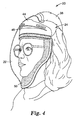
- the protective device of the present invention is light in weight, easy to don and remove, comfortable to wear, provides panoramic viewing, filters exhaled air and supplies filtered inhalation air. It can be used by bearded people, and by people who wear eyeglasses. It is well adapted to provide reciprocal protection for health care workers and patients, and reduces potential contamination from the wearer.
- system of the present invention can be manufactured at substantially lower cost than existing forced air devices and, thus, will allow for broader and more frequent use in hospital, clinical, industrial and office settings.
- face is intended to have its customary meaning, i.e., the anterior part of the human head generally from forehead to chin and extending laterally to, but not including, the ears.
- the face includes the chin, mouth, nose, cheeks, eyes and, usually, the forehead.
- head is intended to have its customary meaning but may also include portions of the neck.
- the present invention may be used a splash or impact protection device. Additionally, the device may provide respiratory protection, either through positive or negative pressure, to the wearer. The invention may also provide protection to a non-wearer against contaminants in a wearer's exhalation.
- the system 20 is very well-suited for use in the health care industry, the system 20 could be used in many other fields, in virtually any situation in which it might be desirable to isolate a person from the environment, e.g., in the pharmaceutical, chemical, electronics industries.
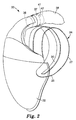
- the present invention provides a protective system 20 having a face shield 22 coupled to a cradle 24.
- the face shield 22 may provide splash and /or impact resistance.
- the face shield 22 is transparent and provides a wide field of view.
- a face shield 22 that provides a panoramic view is preferred.
- the face shield 22 may be made of any suitable material and of any size or shape that provides the desired level of splash and impact resistance.
- clear polycarbonate is a preferred material.
- the face shield 22 is formed to generally conform to the shape and exceed the size of the human face.
- the face shield 22, or lens could be movably or hingedly coupled to the head cradle, and it could be formed of two or more hingedly coupled pieces so that, for example, to drink something without removing the protective system a wearer could open a lower portion (for example) of the face shield 22.
- Cradle 24 is a generally curved or arcuate, spatulate shape.
- the cradle 24 may be fastened to head shield by a number of means, including adhesive, screws or springs.
- the cradle has a free end 25 and a length 27 extending generally between the free end 25 and the attachment to the face shield 22.
- the head cradle 24 is shaped to generally conform to and provide a snug fit against the head of the wearer.
- Cradle 24 is made of a resilient material. All or a portion of its length 27 may be resident. In a preferred embodiment, the material is a clear polyester. Other suitable materials include plastics such as polyolefins and ABS and metals such as spring steel. The resilience may be enhanced by using springs or other similar structures.
- the cradle 24 is sufficiently resilient to permit the free end 25 to generally engage the bottom of occipital protuberance of the wearer's head when in use.
- a reinforcing strip 30 may be added to the cradle 24.
- the reinforcing strip 30 preferably is resilient and may be made of many suitable materials, such as spring steel.
- cradle 24 exerts a gentle, compressive pressure against the wearer's head.
- the pressure is generally generated by the free end 25 of the cradle 24 and a portion of the protective device generally in the vicinity of where the device contacts the wearer's forehead.
- the pressure exerted is sufficient to hold the face shield 22 in place in front of the wearer's face but not so great as to leave substantial pressure marks on the wearer's head.
- the cradle 24 may be used in other applications, such as, for instance, welding applications. In this case, the cradle 24 would be attached to a welding shield.
- cradle 24 may include a head harness 32.
- the head harness 32 stabilizes the face shield 22 on the wearer's head and may articulate with the additional equipment to connect the device 20 to the equipment.
- the head harness 32 may either be part of the additional equipment or be part of the cradle 24.
- the face shield 22 and the wearer's face substantially define a breathing zone.
- This zone may be charged by an airflow generator 36, such as a blower, operably carried on the head cradle 24 or operably connected with a diffuser 44.
- the airflow generator 36 has an intake 37 with an inlet 41 and an outlet 39.
- the air flow generated by airflow generator 36 can be selectively increased or decreased.
- the flow rate is preferably above about 50 liters per minute, with a range of approximately 110 to 170 liters per minute being most preferred.
- An example of a suitable airflow generator 36 is a model W-2949 motor/blower (Minnesota Mining & Manufacturing Company, St. Paul, Minnesota, hereinafter referred to as "3M").
- a pressurized air source may be attached to device instead or in conjunction with the airflow generator 36.
- a filter 38 is connected to the intake 37 to provide filtered air to the breathing zone.
- filter 38 is a multilayer material, having an outer protective layer(s), such as a scrim layer encompassing an inner filter layer(s), such as a microfiber layer.
- the filter 38 is a pliable encompassing member.
- the bag-like filter 38 substantially encompasses at least the blower inlet 41. Examples of suitable filter materials may be found by reference to U.S. Patents 5,620,545 (Braun et al.) and 5,639,700 (Braun et al.), both assigned to 3M.
- the filter may be of varying degrees of flexibility, even approaching substantial rigidity, and may have various stiffness.
- the filter element may include more rigid portions for making it self-supporting in a selected configuration or position with respect to air intake 37 or air inlet 41, or a frame may be provided for this purpose. More than one filter element may be used. Other nonencompassing filters, such as the SERIES 2000 filters by 3M, are suitable for the present invention.
- Intake may be a port, as depicted in Figure 2, or may be a permeable or impermeable support structure.
- the blower 36 may be battery powered or powered by other sources.
- the air flow generator 36 is preferably electrically powered, an electrical current producer such as a battery or solar array being operably associated with the air intake. Directly wired line voltage could be used.
- the power source 40 is contained within filter 38.
- Suitable controls may be provided for the blower, such as a rheostat, slide, toggle or touch on/off switch.
- a spacer 42 may operably be carried near the inlet 41 for spacing the filter 38 from the intake 37.
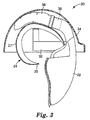
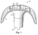
- the portable protective system of the present invention may include a diffuser 44 with an air entry 45 an air exit 46 and a plurality of internal baffles 48.
- the diffuser 44 defines an air flow path.
- the surface 26 of diffuser 44 near the air exit 46 is generally complementary to a human forehead.
- An air-impermeable band 51 may be provided on the diffuser and/or the cradle 24 or face shield 22 to help seal the device to the wearer.
- Diffuser 44 is coupled to face shield 22. Head cradle 24 extends generally rearward from the diffuser 44.
- face shield 22 may carry an exit filter seal 50 for filtering air before it is exhausted from the breathing zone.
- the exit filter seal 50 is generally pliable and is operably coupled to and disposed along all or part of the periphery of the face shield 22. Exit filter is adapted to generally engage and conform to the boundaries of a human face.
- the exit filter seal 50 substantially occupies or fills the space between the face shield and a wearer's face, thereby forming a breathing zone defined by the face shield 22, the surface of the wearer's face, and the exit filter seal 50.
- the exit filter seal 50 prevents the inward flow of unfiltered ambient air while permitting air to be exhausted through the seal from the breathing zone.
- Examples of material suitable for forming the exit filter seal 50 include TYVEK by DuPont, or other generally similar woven or nonwoven webs.
- a carded, thermally bonded nonwoven web comprised of 3 denier polypropylene and polyester fibers is suitable, but a generally similar woven or nonwoven web or a foam material may be used, as long as the selected material precludes contaminated or ambient air from entering the breathing zone.
- the exit filter seal 50 may be adhesively or mechanically attached along the perimeter of the face shield portion 22 using, for example, 3M tape #924.
- the exit filter seal 50 is used in protective devices wherein filtered exhalation is required or desired
- More than one exit filter seal 50 may be used, and the pliability of the exit or exhalation filter(s) may be varied.
- a filter cowl may be used with the present invention.
- the filter cowl drapes loosely from the edge of the face shield 22, substantially occupying or covering the space between the face shield 22 and the user's head particularly the space between the shield 22 and the periphery of a user's face. This defines a breathing zone.
- the cowl may be disposable, designed for a single use, i.e., to be removed after a use and replaced with another cowl.
- the cowl may be used in conjunction with or instead of the exit filter seal 50.
Description
Claims (8)
- A protective system (20), comprising:a diffuser (44) having a surface, an air entry, an air exit, and at least one internal baffle, said diffuser (44) defining an air flow path, said surface generally complementary to a human forehead;a substantially transparent face shield (22) coupled to the diffuser (44);a head cradle (24) extending from the diffuser (44), said head cradle (24) having a free end and a length extending generally between the free end and the diffuser (44), a portion of the length being sufficiently arcuate whereby, when in use, a portion of the head cradle generally conforms to a portion of the top and back of the wearer's head, the head cradle (24) extends generally toward the wearer's occipital promberance and said free end lodges against the wearer's head or neck in a region generally beneath the occipital protuberance;a blower (36) coupled to the diffuser (44) for generating an air flow through the diffuser (44), said blower (36) having an inlet and said blower (36) operably coupled to a power source; anda filter (38) operably coupled to the diffuser.
- The protective system (20) according to claim 1, and further comprising a generally pliable exit seal (50) operably coupled to and disposed along the periphery of the face shield (22) and adapted to generally engage and conform to the boundaries of a human head, thereby forming a breathing zone defined by the face shield (22), the surface of a wearer's face and the exit seal (50).
- The protective system (20) according to claim 1 or 2, wherein the diffuser (44) has an air-impermeable strip (51) attached thereto.
- The protective system (20) according to any of claims 1 to 3, wherein the blower (36) has a blower controller operably connected thereto and carried on the diffuser (44).
- The protective system (20) according to any of claims 2 to 4, wherein the exit seal (50) comprises a nonwoven web connected to the face shield (22).
- The protective system (20) according to claim 5, wherein the exit seal (50) comprises a nonwoven web of polypropylene and polyester fibers attached to the face shield (22).
- The protective system (20) according to any of claims 1 to 6, wherein the filter (38) is a compliant, encompassing filter that at least substantially encompasses the blower inlet.
- A human-face protector comprising:a head cradle (24) having a free end and a length, a portion of the length being sufficiently arcuate whereby, when in use, a portion of the head cradle (24) generally conforms to a portion of the top and back of the wearer's head, the head cradle (24) extends generally toward the wearer's occipital protuberance and said free end lodges against the wearer's head or neck in a region generally beneath the occipital protuberance;a substantially transparent, air-impermeable, rigid face shield (22) extending from one end of the head cradle (24), said face shield (22) having a periphery and formed to generally conform to the shape and exceed the size of a human face;a fibrous face filter seal (50) disposed adjacent to and generally along the periphery of the face shield (22) and adapted to engage and conform to the boundaries of a human face, thereby forming a breathing zone defined by the face shield (22), the surface of the human face and the face filter seal (50) when the protector is worn, wherein air exhausting from the breathing zone is filtered through the face filter seal (50); anda filter (38) for filtering air entering into the breathing zone.
Priority Applications (1)
| Application Number | Priority Date | Filing Date | Title |
|---|---|---|---|
| EP01111254A EP1127588B1 (en) | 1997-08-15 | 1997-12-16 | Protective system for face and respiratory protection |
Applications Claiming Priority (3)
| Application Number | Priority Date | Filing Date | Title |
|---|---|---|---|
| US911833 | 1992-07-10 | ||
| US08/911,833 US6014971A (en) | 1997-08-15 | 1997-08-15 | Protective system for face and respiratory protection |
| PCT/US1997/023712 WO1999008752A1 (en) | 1997-08-15 | 1997-12-16 | Protective system for face and respiratory protection |
Related Child Applications (1)
| Application Number | Title | Priority Date | Filing Date |
|---|---|---|---|
| EP01111254A Division EP1127588B1 (en) | 1997-08-15 | 1997-12-16 | Protective system for face and respiratory protection |
Publications (2)
| Publication Number | Publication Date |
|---|---|
| EP1003590A1 EP1003590A1 (en) | 2000-05-31 |
| EP1003590B1 true EP1003590B1 (en) | 2004-11-10 |
Family
ID=25430931
Family Applications (2)
| Application Number | Title | Priority Date | Filing Date |
|---|---|---|---|
| EP01111254A Expired - Lifetime EP1127588B1 (en) | 1997-08-15 | 1997-12-16 | Protective system for face and respiratory protection |
| EP97954213A Expired - Lifetime EP1003590B1 (en) | 1997-08-15 | 1997-12-16 | Protective system for face and respiratory protection |
Family Applications Before (1)
| Application Number | Title | Priority Date | Filing Date |
|---|---|---|---|
| EP01111254A Expired - Lifetime EP1127588B1 (en) | 1997-08-15 | 1997-12-16 | Protective system for face and respiratory protection |
Country Status (10)
| Country | Link |
|---|---|
| US (3) | US6014971A (en) |
| EP (2) | EP1127588B1 (en) |
| JP (1) | JP4119090B2 (en) |
| KR (1) | KR100526271B1 (en) |
| AU (1) | AU5805198A (en) |
| BR (1) | BR9714815A (en) |
| CA (1) | CA2300429A1 (en) |
| DE (2) | DE69731559T2 (en) |
| ES (1) | ES2231905T3 (en) |
| WO (1) | WO1999008752A1 (en) |
Cited By (1)
| Publication number | Priority date | Publication date | Assignee | Title |
|---|---|---|---|---|
| USD881380S1 (en) | 2017-10-16 | 2020-04-14 | Gentex Corporation | Respirator |
Families Citing this family (95)
| Publication number | Priority date | Publication date | Assignee | Title |
|---|---|---|---|---|
| US6014971A (en) * | 1997-08-15 | 2000-01-18 | 3M Innovative Properties Company | Protective system for face and respiratory protection |
| US6584976B2 (en) * | 1998-07-24 | 2003-07-01 | 3M Innovative Properties Company | Face mask that has a filtered exhalation valve |
| US6382208B2 (en) * | 1998-11-02 | 2002-05-07 | Board Of Regents University Of Nebraska | System for controlling the internal temperature of a respirator |
| US6371116B1 (en) * | 1999-06-24 | 2002-04-16 | Todd A. Resnick | Method and apparatus for pressurizing a protective hood enclosure with exhaled air |
| EP1286604B1 (en) | 2000-01-18 | 2008-04-30 | Stryker Corporation | Air filtration system including a helmet assembly with at least two air outlets to distribute air about a head of a user |
| US6279172B1 (en) | 2000-02-02 | 2001-08-28 | Gentex Corporation | Custom fitting assembly for helmet |
| US6374823B1 (en) * | 2000-03-14 | 2002-04-23 | Mohammed Ali Hajianpour | Disposable ventilated face shield and head covering |
| US6460539B1 (en) | 2000-09-21 | 2002-10-08 | 3M Innovative Properties Company | Respirator that includes an integral filter element, an exhalation valve, and impactor element |
| US6792951B2 (en) * | 2000-11-03 | 2004-09-21 | Evonitz, Iii Alex V. | Breathable air pressurized safety helmet |
| US7036502B2 (en) | 2002-04-08 | 2006-05-02 | Joseph Manne | Air curtain device |
| US20030192536A1 (en) * | 2002-04-12 | 2003-10-16 | Raymond Odell | Personal containment system with isolated blower |
| US6948191B2 (en) * | 2002-04-12 | 2005-09-27 | 3M Innovative Properties Company | Personal protective suit with partial flow restriction |
| US6796304B2 (en) | 2002-04-12 | 2004-09-28 | 3M Innovative Properties Company | Personal containment system with sealed passthrough |
| US6823867B2 (en) * | 2002-04-12 | 2004-11-30 | 3M Innovative Properties Company | Pouch for the blower unit of a powered air purifying respirator |
| US8261375B1 (en) | 2003-06-19 | 2012-09-11 | Reaux Brian K | Method of forming a protective covering for the face and eyes |
| US20050108813A1 (en) * | 2003-07-10 | 2005-05-26 | Cylena Medical Technologies Inc. | Protective apparel spacers and low resistance air flow |
| US20070192947A1 (en) * | 2003-07-10 | 2007-08-23 | Cylena Medical Technologies Inc. | Protective apparel with improved doffing |
| US6990691B2 (en) * | 2003-07-18 | 2006-01-31 | Depuy Products, Inc. | Head gear apparatus |
| US6973676B1 (en) | 2003-09-02 | 2005-12-13 | Elwood Jesse Bill Simpson | Protective helmet with integral air supply |
| US7156093B2 (en) * | 2003-09-18 | 2007-01-02 | E. D. Bullard Company | Inflatable respirator hood |
| US6918141B2 (en) * | 2003-09-23 | 2005-07-19 | Pabbon Development, Inc. | Protective headgear system |
| US7357135B2 (en) * | 2004-09-08 | 2008-04-15 | Steel Grip, Inc. | Protective hood with fan assembly |
| US7320722B2 (en) * | 2004-10-29 | 2008-01-22 | 3M Innovative Properties Company | Respiratory protection device that has rapid threaded clean air source attachment |
| US7197774B2 (en) * | 2004-11-12 | 2007-04-03 | 3M Innovative Properties Company | Supplied air helmet having face seal with differentiated permeability |
| US20060107431A1 (en) | 2004-11-12 | 2006-05-25 | Curran Desmond T | Supplied air helmet having a knitted face seal |
| US20060101552A1 (en) * | 2004-11-15 | 2006-05-18 | Lee Peter D | Frictionally engaged supplied air helmet face seal |
| US7419526B2 (en) * | 2005-03-03 | 2008-09-02 | 3M Innovative Properties Company | Conformal filter cartridges and methods |
| CA2845907C (en) * | 2005-03-24 | 2016-10-04 | Stryker Corporation | Method of manufacturing a hood for use with a personal protection system |
| US6996846B1 (en) * | 2005-06-02 | 2006-02-14 | Armen Karapetyan | Visor-type face shield for dentist |
| US7937775B2 (en) | 2005-08-09 | 2011-05-10 | Microtek Medical, Inc. | Surgical protective head gear assembly including high volume air delivery system |
| US20070050898A1 (en) * | 2005-08-09 | 2007-03-08 | Larson Keith A | Surgical protective system and assembly having a head gear assembly supporting a surgical garment and air delivery system |
| US7694353B2 (en) * | 2005-11-23 | 2010-04-13 | Brian Weston | Air circulation system for protective helmet and helmet containing the same |
| FI118724B (en) * | 2006-04-20 | 2008-02-29 | Euromaski Oy | Protective device |
| KR100763720B1 (en) * | 2007-03-21 | 2007-10-04 | 유광선 | A face protector for working |
| WO2008118768A1 (en) * | 2007-03-23 | 2008-10-02 | 3M Innovative Properties Company | Air delivery apparatus for respirator hood |
| US20100108067A1 (en) | 2007-03-23 | 2010-05-06 | Walker Garry J | Respirator flow control apparatus and method |
| EP2144674A4 (en) * | 2007-04-13 | 2012-12-26 | Invacare Corp | Apparatus and method for providing positive airway pressure |
| US7823586B2 (en) * | 2007-07-25 | 2010-11-02 | Mark Glazman | Personal respiratory protection system |
| CN101815557B (en) * | 2007-10-05 | 2012-12-19 | 3M创新有限公司 | Respirator flow control apparatus and method |
| CN101909698B (en) * | 2007-11-12 | 2014-03-12 | 3M创新有限公司 | Respirator assembly with air flow direction control |
| US8234722B2 (en) * | 2007-12-14 | 2012-08-07 | Stryker Corporation | Personal protection system with head unit having easy access controls and protective covering having glare avoiding face shield |
| PL2271407T3 (en) * | 2008-04-04 | 2019-09-30 | 3M Innovative Properties Company | Respirator system including convertible head covering member |
| CA2720226C (en) * | 2008-04-04 | 2017-09-19 | Pierre Legare | Air filtration device |
| US8185969B2 (en) | 2009-09-15 | 2012-05-29 | Wrong Gear, Inc. | Protective gear |
| CA135170S (en) * | 2009-11-02 | 2011-05-03 | Scott Health & Safety Ltd | Breathing mask |
| SE534951C2 (en) * | 2010-06-18 | 2012-02-28 | Facecover Sweden Ab | Motor-driven Air Purifying Respirator (PAPR) |
| JP5693360B2 (en) * | 2011-05-05 | 2015-04-01 | 石田 豊治 | Disaster hood |
| US9993605B2 (en) * | 2011-06-21 | 2018-06-12 | Resmed Limited | PAP system |
| KR20140068041A (en) | 2011-08-01 | 2014-06-05 | 쓰리엠 이노베이티브 프로퍼티즈 캄파니 | Respiratory assembly including latching mechanism |
| US9700743B2 (en) | 2012-07-31 | 2017-07-11 | 3M Innovative Properties Company | Respiratory assembly including latching mechanism |
| US9155923B2 (en) | 2011-12-06 | 2015-10-13 | East Carolina University | Portable respirators suitable for agricultural workers |
| US8899227B2 (en) | 2011-12-15 | 2014-12-02 | 3M Innovative Properties Company | Air filtration device having subsections lacking fluid communication |
| US8887719B2 (en) | 2011-12-15 | 2014-11-18 | 3M Innovative Properties Company | Air filtration device having tuned air distribution system |
| US9510626B2 (en) | 2013-02-01 | 2016-12-06 | 3M Innovative Properties Company | Sleeve-fit respirator cartridge |
| JP6455653B2 (en) * | 2013-12-26 | 2019-01-23 | 株式会社メトラン | Filter structure |
| USD822210S1 (en) | 2015-06-09 | 2018-07-03 | Lincoln Global, Inc. | Extended battery of a powered air purifying respirator |
| USD820455S1 (en) | 2015-06-09 | 2018-06-12 | Lincoln Global, Inc. | Filter cover of a powered air purifying respirator |
| USD810299S1 (en) | 2015-06-09 | 2018-02-13 | Lincoln Global, Inc. | Battery of a powered air purifying respirator |
| USD820456S1 (en) | 2015-06-09 | 2018-06-12 | Lincoln Global, Inc. | Belt bracket of powered air purifying respirator |
| WO2018075638A1 (en) * | 2016-10-19 | 2018-04-26 | Teleflex Medical Incorporated | Moisture removal and condensation and humidity management apparatus for a breathing circuit |
| US10960165B2 (en) | 2017-07-10 | 2021-03-30 | Teleflex Medical Incorporated | Moisture removal and condensation and humidity management apparatus for a breathing circuit |
| USD848077S1 (en) | 2018-03-07 | 2019-05-07 | Lincoln Global, Inc. | Cover lens frame |
| USD860546S1 (en) | 2018-03-07 | 2019-09-17 | Lincoln Global, Inc. | Top shell for helmet |
| USD857306S1 (en) | 2018-03-07 | 2019-08-20 | Lincoln Global, Inc. | Top of helmet shell |
| USD853044S1 (en) | 2018-03-07 | 2019-07-02 | Lincoln Global, Inc. | Inner shell of a helmet |
| CN108452450A (en) * | 2018-03-22 | 2018-08-28 | 军事科学院系统工程研究院卫勤保障技术研究所 | A kind of negative pressure Isolation head hood |
| USD851841S1 (en) | 2018-03-23 | 2019-06-18 | Lincoln Global, Inc. | Shield holder frame |
| US20200375281A1 (en) * | 2019-05-28 | 2020-12-03 | Honeywell International Inc. | Protective face shield assembly |
| WO2021050916A1 (en) * | 2019-09-12 | 2021-03-18 | O2-O2, Inc. | Respirator devices with source control mechanisms and associated systems and methods |
| JP7272287B2 (en) * | 2020-01-16 | 2023-05-12 | 豊田合成株式会社 | Functional part mounting structure |
| DE112020007023A5 (en) | 2020-04-04 | 2023-01-12 | Dirk Barnstedt | SYSTEM FOR VENTILATION OF INDIVIDUAL WORKPLACES TO PREVENT DROPLET INFECTIONS |
| DE102020109503A1 (en) | 2020-04-06 | 2021-10-07 | Thierry Lucas | Infection protection mask for hygiene applications |
| FR3111081A1 (en) * | 2020-06-09 | 2021-12-10 | soufiane SAMAKI | Positive pressure visor |
| TR202009416A2 (en) * | 2020-06-17 | 2020-07-21 | Maltepe Ueniversitesi Teknoloji Transfer Ofisi Anonim Sirketi | DISINFECTED AIR FLOW PROTECTION VENT HEAD |
| DE202020103893U1 (en) | 2020-07-06 | 2021-01-28 | Georg Hölzl | Respiratory protection device |
| EP3939667A1 (en) * | 2020-07-13 | 2022-01-19 | Mat Product & Technology, SL | Ventilated cooling and protective garment with facial shield |
| US20230263244A1 (en) * | 2020-07-13 | 2023-08-24 | Mat Product & Technology, Sl | Ventilated cooling and protective garment with facial shield |
| EP4181725A1 (en) * | 2020-07-15 | 2023-05-24 | Technion Research & Development Foundation Limited | Personal wearable air curtain shield |
| US20220016450A1 (en) * | 2020-07-17 | 2022-01-20 | Hall Labs Llc | Head Covering Device Providing Filtered Intake and Exhaust Air |
| US20220016451A1 (en) * | 2020-07-17 | 2022-01-20 | Hall Labs Llc | Personal Air Filtering Device with Air Mover Pulling Air Out of the Device |
| US11065479B1 (en) * | 2020-08-18 | 2021-07-20 | Alexander P Rafalovich | Portable air powered respirator |
| CN111905202B (en) * | 2020-08-21 | 2023-01-24 | 河南中医药大学第一附属医院 | Special gasification traditional chinese medical science nursing device of asthma patient |
| NO20201067A1 (en) * | 2020-09-30 | 2022-03-31 | Peakvent As | A face shield for being arranged in front of a portion of the face of a user |
| WO2022074426A1 (en) * | 2020-10-06 | 2022-04-14 | Кирилл КУЛАКОВСКИЙ | Personal air filtration system |
| WO2022086790A1 (en) * | 2020-10-19 | 2022-04-28 | Avox Systems Inc. | De-misting system for a mask and associated methods |
| WO2022155713A1 (en) * | 2021-01-20 | 2022-07-28 | Faria Wallace | Personal protective equipment against airborne contagious agents |
| US11318221B1 (en) | 2021-01-26 | 2022-05-03 | James Joseph Wade | Wearable air cleaner with ultraviolet light disinfection |
| US11925820B2 (en) | 2021-03-19 | 2024-03-12 | Razor Edge Systems, Inc. | Two-way protective respirator system with positive air flow against airborne contaminant particles and vapor components |
| US20220295923A1 (en) * | 2021-03-22 | 2022-09-22 | Hall Labs Llc | Head Covering Device Providing Filtered Intake and Exhaust Air |
| US11318333B1 (en) * | 2021-04-17 | 2022-05-03 | Christopher T. Ellerbrake | Respiratory protection system |
| US11202925B1 (en) * | 2021-04-21 | 2021-12-21 | Wadie M. Awad | Full face and head mask |
| USD986510S1 (en) | 2021-05-11 | 2023-05-16 | Barbara D Leschinsky | Wearable air sterilizer with slidable face shield |
| GB2607024A (en) * | 2021-05-21 | 2022-11-30 | World Wide Welding Ltd | Soft hood with outlet filter |
| KR102542490B1 (en) * | 2021-07-19 | 2023-06-12 | 엘지전자 주식회사 | Mask apparatus |
| WO2023161536A1 (en) * | 2022-02-25 | 2023-08-31 | Werlax Invest, S.L. | Air filtration device for protection |
Family Cites Families (44)
| Publication number | Priority date | Publication date | Assignee | Title |
|---|---|---|---|---|
| US2364571A (en) * | 1943-10-08 | 1944-12-05 | Wilson Athletic Goods Mfg Co I | Boxer's helmet |
| US3223086A (en) * | 1963-08-05 | 1965-12-14 | Arthur R Adams | Air-conditioned helmet |
| US3362403A (en) * | 1963-12-11 | 1968-01-09 | Robertshaw Controls Co | Unified helmet and oxygen breathing assembly |
| US3600713A (en) * | 1969-07-07 | 1971-08-24 | Mike C Holt | Athletic helmet |
| US3713640A (en) * | 1970-07-27 | 1973-01-30 | Riddell | Energy absorbing and sizing means for helmets |
| US3955570A (en) * | 1972-05-18 | 1976-05-11 | Physical Systems, Inc. | Surgical exhaust mask |
| US4055172A (en) | 1973-07-18 | 1977-10-25 | Josef Ender | Nail and set for correctly resetting fractured bones for their immediate re-use |
| US3906548A (en) * | 1974-10-24 | 1975-09-23 | Bert J Kallis | Sweat band for a hard hat suspension unit |
| US3934271A (en) * | 1974-11-27 | 1976-01-27 | Jhoon Rhee | Protective helmet |
| US3992722A (en) * | 1974-11-27 | 1976-11-23 | Jhoon Goo Rhee | Protective helmet |
| US4055173A (en) * | 1975-04-21 | 1977-10-25 | Knab James V | Surgical masking and ventilating system |
| US4058854A (en) * | 1975-07-24 | 1977-11-22 | Jhoon Goo Rhee | Protective helmet |
| US4019508A (en) * | 1976-05-21 | 1977-04-26 | Research Development Systems, Inc. | Wearable, self-contained fully mobile personal breathing apparatus for surgeons and operating room personnel |
| GB2032284B (en) * | 1978-10-02 | 1982-11-10 | Racal Safety Ltd | Breathing apparatus |
| DE2847869C2 (en) * | 1978-11-03 | 1980-11-27 | Metzeler Schaum Gmbh, 8940 Memmingen | Head protection made of polyurethane foam for athletes |
| US4286339A (en) * | 1978-12-04 | 1981-09-01 | Coombs Peter A | Fireman's helmet with energy absorbing liner |
| US4287613A (en) * | 1979-07-09 | 1981-09-08 | Riddell, Inc. | Headgear with energy absorbing and sizing means |
| GB2061696B (en) * | 1979-10-30 | 1984-05-16 | Martindale Protection Ltd | Protective respiratory helmet |
| US4280491A (en) * | 1980-03-07 | 1981-07-28 | Minnesota Mining And Manufacturing Company | Powered air respirator |
| US4462399A (en) * | 1981-10-02 | 1984-07-31 | Minnesota Mining And Manufacturing Company | Powered air respirator and cartridge |
| US4453277A (en) * | 1982-08-20 | 1984-06-12 | The United States Of America As Represented By The Secretary Of The Army | Protective helmet |
| US4676236A (en) * | 1983-09-09 | 1987-06-30 | Gentex Corporation | Helmet airflow system |
| JPH0649085B2 (en) * | 1985-11-15 | 1994-06-29 | ブリティッシュ・テクノロジー・グループ・リミテッド | Respiratory protection for dust with self-contained electric fan |
| US4965887A (en) * | 1987-11-12 | 1990-10-30 | John A. Paoluccio | Face protector for splash and spatter protection |
| US5003973A (en) * | 1988-01-15 | 1991-04-02 | Ford Theodore H | Rescue helmet apparatus |
| GB8809221D0 (en) * | 1988-04-19 | 1988-05-25 | Safety Products Ltd | Improvements in/relating to safety visors |
| US4901716A (en) * | 1989-02-06 | 1990-02-20 | Stackhouse Wyman H | Clean room helmet system |
| US5177815A (en) * | 1990-04-09 | 1993-01-12 | Andujar Edward M | Protective headgear |
| US5410757A (en) * | 1990-06-01 | 1995-05-02 | Kemira Oy | Face shield |
| US5054480A (en) * | 1990-06-14 | 1991-10-08 | Bio Medical Devices, Inc. | Personal air filtration and control system |
| US5283914A (en) * | 1990-12-20 | 1994-02-08 | Coal Industry (Patents) Limited | Protective helmets |
| USH1360H (en) * | 1991-04-24 | 1994-10-04 | The United States Of America, As Represented By The Secretary Of The Army | Lightweight protective gas mask and hood |
| US5104430A (en) * | 1991-06-11 | 1992-04-14 | Her Mou Lin | Mask with an air filtering device |
| NO174767C (en) * | 1991-11-29 | 1994-07-06 | Erik W Bahr | breathing mask |
| US5533500A (en) * | 1992-03-04 | 1996-07-09 | Her-Mou; Lin | Helmet with an air filtering device |
| USD357555S (en) * | 1992-03-16 | 1995-04-18 | Georg Brueckner | Head protector for pugilistic sports |
| US5315718A (en) * | 1992-04-30 | 1994-05-31 | The United States Of America As Represented By The Secretary Of The Army | Protective helmet and retention system therefor |
| US5381560A (en) * | 1993-03-23 | 1995-01-17 | Pdh Corporation | Fitting and retention system for headgear |
| US5659900A (en) * | 1993-07-08 | 1997-08-26 | Bell Sports, Inc. | Sizing and stabilizing apparatus for bicycle helmets |
| US5588153A (en) * | 1995-04-28 | 1996-12-31 | Stackhouse, Inc. | Surgical gown |
| US5592936A (en) * | 1995-08-28 | 1997-01-14 | Stackhouse, Inc. | Surgical helmet |
| US5711033A (en) * | 1995-10-05 | 1998-01-27 | Bio-Medical Devices, Inc. | Air filtration and control system including head gear |
| US5774901A (en) * | 1996-08-15 | 1998-07-07 | Bell Sports, Inc. | Sport helmet retention apparatus |
| US6014971A (en) * | 1997-08-15 | 2000-01-18 | 3M Innovative Properties Company | Protective system for face and respiratory protection |
-
1997
- 1997-08-15 US US08/911,833 patent/US6014971A/en not_active Expired - Lifetime
- 1997-12-16 DE DE69731559T patent/DE69731559T2/en not_active Expired - Lifetime
- 1997-12-16 AU AU58051/98A patent/AU5805198A/en not_active Abandoned
- 1997-12-16 KR KR10-2000-7001422A patent/KR100526271B1/en not_active IP Right Cessation
- 1997-12-16 BR BR9714815-6A patent/BR9714815A/en not_active IP Right Cessation
- 1997-12-16 EP EP01111254A patent/EP1127588B1/en not_active Expired - Lifetime
- 1997-12-16 CA CA002300429A patent/CA2300429A1/en not_active Abandoned
- 1997-12-16 ES ES97954213T patent/ES2231905T3/en not_active Expired - Lifetime
- 1997-12-16 EP EP97954213A patent/EP1003590B1/en not_active Expired - Lifetime
- 1997-12-16 WO PCT/US1997/023712 patent/WO1999008752A1/en active IP Right Grant
- 1997-12-16 DE DE69732806T patent/DE69732806T2/en not_active Expired - Lifetime
- 1997-12-16 JP JP2000509487A patent/JP4119090B2/en not_active Expired - Fee Related
-
1999
- 1999-09-20 US US09/399,539 patent/US6250299B1/en not_active Expired - Lifetime
- 1999-09-20 US US09/399,871 patent/US6279572B1/en not_active Expired - Lifetime
Cited By (1)
| Publication number | Priority date | Publication date | Assignee | Title |
|---|---|---|---|---|
| USD881380S1 (en) | 2017-10-16 | 2020-04-14 | Gentex Corporation | Respirator |
Also Published As
| Publication number | Publication date |
|---|---|
| JP2001514948A (en) | 2001-09-18 |
| DE69732806D1 (en) | 2005-04-21 |
| KR100526271B1 (en) | 2005-11-08 |
| WO1999008752A1 (en) | 1999-02-25 |
| KR20010022820A (en) | 2001-03-26 |
| CA2300429A1 (en) | 1999-02-25 |
| US6014971A (en) | 2000-01-18 |
| US6279572B1 (en) | 2001-08-28 |
| JP4119090B2 (en) | 2008-07-16 |
| AU5805198A (en) | 1999-03-08 |
| DE69731559D1 (en) | 2004-12-16 |
| ES2231905T3 (en) | 2005-05-16 |
| EP1127588A2 (en) | 2001-08-29 |
| EP1127588A3 (en) | 2003-02-12 |
| EP1127588B1 (en) | 2005-03-16 |
| EP1003590A1 (en) | 2000-05-31 |
| DE69731559T2 (en) | 2005-11-24 |
| BR9714815A (en) | 2000-07-25 |
| DE69732806T2 (en) | 2006-04-06 |
| US6250299B1 (en) | 2001-06-26 |
Similar Documents
| Publication | Publication Date | Title |
|---|---|---|
| EP1003590B1 (en) | Protective system for face and respiratory protection | |
| US6732733B1 (en) | Half-mask respirator with head harness assembly | |
| US5067174A (en) | Protective headgear | |
| US20040226563A1 (en) | Face Mask with Double Breathing Chambers | |
| AU703897B2 (en) | Disposable mask and suction catheter | |
| US4019508A (en) | Wearable, self-contained fully mobile personal breathing apparatus for surgeons and operating room personnel | |
| US20210308496A1 (en) | Respiratory mask | |
| KR20070085345A (en) | Frictionally engaged supplied air helmet face seal | |
| WO2023086609A1 (en) | Combined face shield and mask assembly | |
| CN211835878U (en) | Sterile air supply breathing cap | |
| US20210339056A1 (en) | Respirator to Accommodate Facial Hair | |
| US20210353977A1 (en) | Integrated respiratory and eye protective system | |
| CN213527206U (en) | Portable virus protective mask | |
| US20220305303A1 (en) | Facepiece chin retention feature | |
| JP2021172905A (en) | Medical mask | |
| US20230372745A1 (en) | Breath protection device | |
| CN218739921U (en) | Air purification hood | |
| CN212282593U (en) | Respirator with night vision function | |
| GB2597479A (en) | Protective hood | |
| GB2593928A (en) | Hood |
Legal Events
| Date | Code | Title | Description |
|---|---|---|---|
| PUAI | Public reference made under article 153(3) epc to a published international application that has entered the european phase |
Free format text: ORIGINAL CODE: 0009012 |
|
| 17P | Request for examination filed |
Effective date: 20000314 |
|
| AK | Designated contracting states |
Kind code of ref document: A1 Designated state(s): DE ES FR GB IT |
|
| 17Q | First examination report despatched |
Effective date: 20000904 |
|
| GRAP | Despatch of communication of intention to grant a patent |
Free format text: ORIGINAL CODE: EPIDOSNIGR1 |
|
| GRAS | Grant fee paid |
Free format text: ORIGINAL CODE: EPIDOSNIGR3 |
|
| GRAA | (expected) grant |
Free format text: ORIGINAL CODE: 0009210 |
|
| AK | Designated contracting states |
Kind code of ref document: B1 Designated state(s): DE ES FR GB IT |
|
| REG | Reference to a national code |
Ref country code: GB Ref legal event code: FG4D |
|
| REF | Corresponds to: |
Ref document number: 69731559 Country of ref document: DE Date of ref document: 20041216 Kind code of ref document: P |
|
| REG | Reference to a national code |
Ref country code: ES Ref legal event code: FG2A Ref document number: 2231905 Country of ref document: ES Kind code of ref document: T3 |
|
| PLBE | No opposition filed within time limit |
Free format text: ORIGINAL CODE: 0009261 |
|
| STAA | Information on the status of an ep patent application or granted ep patent |
Free format text: STATUS: NO OPPOSITION FILED WITHIN TIME LIMIT |
|
| ET | Fr: translation filed | ||
| 26N | No opposition filed |
Effective date: 20050811 |
|
| PGFP | Annual fee paid to national office [announced via postgrant information from national office to epo] |
Ref country code: ES Payment date: 20061226 Year of fee payment: 10 |
|
| PGFP | Annual fee paid to national office [announced via postgrant information from national office to epo] |
Ref country code: IT Payment date: 20061231 Year of fee payment: 10 |
|
| REG | Reference to a national code |
Ref country code: ES Ref legal event code: FD2A Effective date: 20071217 |
|
| PG25 | Lapsed in a contracting state [announced via postgrant information from national office to epo] |
Ref country code: ES Free format text: LAPSE BECAUSE OF NON-PAYMENT OF DUE FEES Effective date: 20071217 |
|
| PGFP | Annual fee paid to national office [announced via postgrant information from national office to epo] |
Ref country code: GB Payment date: 20081229 Year of fee payment: 12 |
|
| PG25 | Lapsed in a contracting state [announced via postgrant information from national office to epo] |
Ref country code: IT Free format text: LAPSE BECAUSE OF NON-PAYMENT OF DUE FEES Effective date: 20071216 |
|
| PGFP | Annual fee paid to national office [announced via postgrant information from national office to epo] |
Ref country code: FR Payment date: 20081217 Year of fee payment: 12 |
|
| GBPC | Gb: european patent ceased through non-payment of renewal fee |
Effective date: 20091216 |
|
| REG | Reference to a national code |
Ref country code: FR Ref legal event code: ST Effective date: 20100831 |
|
| PG25 | Lapsed in a contracting state [announced via postgrant information from national office to epo] |
Ref country code: FR Free format text: LAPSE BECAUSE OF NON-PAYMENT OF DUE FEES Effective date: 20091231 |
|
| PG25 | Lapsed in a contracting state [announced via postgrant information from national office to epo] |
Ref country code: GB Free format text: LAPSE BECAUSE OF NON-PAYMENT OF DUE FEES Effective date: 20091216 |
|
| PGFP | Annual fee paid to national office [announced via postgrant information from national office to epo] |
Ref country code: DE Payment date: 20121213 Year of fee payment: 16 |
|
| REG | Reference to a national code |
Ref country code: DE Ref legal event code: R119 Ref document number: 69731559 Country of ref document: DE |
|
| REG | Reference to a national code |
Ref country code: DE Ref legal event code: R119 Ref document number: 69731559 Country of ref document: DE Effective date: 20140701 |
|
| PG25 | Lapsed in a contracting state [announced via postgrant information from national office to epo] |
Ref country code: DE Free format text: LAPSE BECAUSE OF NON-PAYMENT OF DUE FEES Effective date: 20140701 |