EP2117199B1 - Transmission method, system and router based on the border gateway protocol - Google Patents
Transmission method, system and router based on the border gateway protocol Download PDFInfo
- Publication number
- EP2117199B1 EP2117199B1 EP08773221A EP08773221A EP2117199B1 EP 2117199 B1 EP2117199 B1 EP 2117199B1 EP 08773221 A EP08773221 A EP 08773221A EP 08773221 A EP08773221 A EP 08773221A EP 2117199 B1 EP2117199 B1 EP 2117199B1
- Authority
- EP
- European Patent Office
- Prior art keywords
- data packet
- route
- standby route
- standby
- router
- Prior art date
- Legal status (The legal status is an assumption and is not a legal conclusion. Google has not performed a legal analysis and makes no representation as to the accuracy of the status listed.)
- Active
Links
- 238000000034 method Methods 0.000 title claims abstract description 38
- 230000005540 biological transmission Effects 0.000 title claims abstract description 27
- 238000002372 labelling Methods 0.000 description 5
- 230000015572 biosynthetic process Effects 0.000 description 3
- 230000001419 dependent effect Effects 0.000 description 2
- 238000012986 modification Methods 0.000 description 2
- 230000004048 modification Effects 0.000 description 2
- 238000004891 communication Methods 0.000 description 1
- 238000005538 encapsulation Methods 0.000 description 1
- 238000005516 engineering process Methods 0.000 description 1
- 230000002265 prevention Effects 0.000 description 1
Images


Classifications
-
- H—ELECTRICITY
- H04—ELECTRIC COMMUNICATION TECHNIQUE
- H04L—TRANSMISSION OF DIGITAL INFORMATION, e.g. TELEGRAPHIC COMMUNICATION
- H04L45/00—Routing or path finding of packets in data switching networks
- H04L45/02—Topology update or discovery
- H04L45/04—Interdomain routing, e.g. hierarchical routing
-
- H—ELECTRICITY
- H04—ELECTRIC COMMUNICATION TECHNIQUE
- H04L—TRANSMISSION OF DIGITAL INFORMATION, e.g. TELEGRAPHIC COMMUNICATION
- H04L45/00—Routing or path finding of packets in data switching networks
- H04L45/18—Loop-free operations
-
- H—ELECTRICITY
- H04—ELECTRIC COMMUNICATION TECHNIQUE
- H04L—TRANSMISSION OF DIGITAL INFORMATION, e.g. TELEGRAPHIC COMMUNICATION
- H04L45/00—Routing or path finding of packets in data switching networks
- H04L45/22—Alternate routing
-
- H—ELECTRICITY
- H04—ELECTRIC COMMUNICATION TECHNIQUE
- H04L—TRANSMISSION OF DIGITAL INFORMATION, e.g. TELEGRAPHIC COMMUNICATION
- H04L45/00—Routing or path finding of packets in data switching networks
- H04L45/28—Routing or path finding of packets in data switching networks using route fault recovery
-
- H—ELECTRICITY
- H04—ELECTRIC COMMUNICATION TECHNIQUE
- H04L—TRANSMISSION OF DIGITAL INFORMATION, e.g. TELEGRAPHIC COMMUNICATION
- H04L45/00—Routing or path finding of packets in data switching networks
- H04L45/50—Routing or path finding of packets in data switching networks using label swapping, e.g. multi-protocol label switch [MPLS]
Definitions
- the present invention relates to the communication field, and more particularly to a transmission method, system, and router based on a border gateway protocol (BGP).
- BGP border gateway protocol
- a border gateway protocol is an inter-autonomous system (AS) dynamic routing protocol, which is not aimed to discover or calculate a route, but to control route propagation and select an optimal route, i.e., to automatically exchange loop-free AS path reachability information among the ASs, so as to construct a topology of an autonomous region, thereby eliminating the routing loops.
- AS is defined as a set of routers under the same technical administration and using the same routing policy
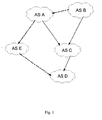
- Figure 1 is a schematic view of a BGP network in the prior art.
- an AS A has two loop-free routes to an AS D, which are that the AS A reaches the AS D via an AS C, and the AS A reaches the AS D via an AS E.
- the AS A selects an optimal route, for example, the loop-free route passing through the AS C, and notifies the optimal route to the AS C in the process of inter-AS route exchange.
- the Internet has become the bearer network of more and more services, increasingly high reliability of the Internet is required.
- the robustness of the BGP greatly affects the reliability indices of the Internet.
- the AS A and the AS B both need to reach the AS D via the AS C, and the AS A also has a sub-optimal route passing through the AS E in addition to the optimal route through the AS C.
- the AS C cannot obtain information about the sub-optimal route.
- the routing protocol between the ASs needs to recalculate the routes that reflect the latest topology, which is called a "convergence" process.
- the AS C may discard data packets sent from the AS A and the AS B till a new route is discovered after the convergence process is completed. For example, if the discovered new route is the sub-optimal route passing through the AS E, the AS C and the AS B respectively transmit data packets to the AS D via the AS A and the AS E. It can be seen that the data packets sent to the AS C whose destination is the AS D are discarded in the process of waiting for the convergence, thus resulting in a flow interruption.
- the AS A In order to solve the problem of temporary flow interruption occurring in the process of waiting for the BGP convergence, in a resilient BGP (RBGP) method, the AS A notifies the pre-calculated sub-optimal route to the AS C as a standby route. In this manner, when the connection between the AS C and the AS D is interrupted, the AS C forwards the data packets whose destination is the AS D to the AS A via the standby route, and then the AS A transmits the data packets to the AS D via the AS E. As such, in the process of waiting for the BGP convergence, the data packets are forwarded via the pre-calculated standby route, and thus the flow will not be interrupted.
- RBGP resilient BGP
- the router within the AS A still uses the AS C as a next-hop AS to the AS D. If the AS A fails to identify that the data packets need to be forwarded via the sub-optimal route, the data packets will be forwarded to the AS C again, so that a loop is formed between the AS C and the AS A.
- US patent application No. 2007/091796 A1 discloses a method of implementing a backup path in an autonomous system. The method is implemented within an autonomous system. In order to protect packets, the router A sets "P-bit" and "Forwarding helper" in the packet, when router B receives the preset packets, router B reads the "P-bit” and "Forwarding helper” and forwards the packet per the backup route. The routers A and B must within a same AS. US patent application No. 2007/070883 A1 is related to resilient routing systems and methods.
- a data packet is forwarded via a standby route corresponding to a data packet ID carried in the data packet.
- a data packet that needs to be forwarded via a standby route can be identified according to a data packet ID carried in the data packet, thus preventing the data packet sent by the sender from being forwarded back to the sender due to a failure to identify the data packet in the BGP convergence process, i.e., avoiding the formation of a data packet forwarding loop in the BGP convergence process. Therefore, the robustness of the BGP network is enhanced and the transmission performance based on the BGP is improved.
- FIG. 1 is a schematic view of a border gateway protocol (BGP) network in the prior art
- Figure 2 is a flow chart of a transmission method based on a BGP according to a first embodiment of the present invention.
- Figure 3 is a schematic structural view of a transmission system based on a BGP according to a second embodiment of the present invention.
- a method provided in an embodiment of the present invention includes: notifying a standby route to a peer autonomous system (AS); receiving a data packet carrying a data packet ID; and forwarding the data packet via a standby route corresponding to the data packet ID.
- AS peer autonomous system
- a system provided in an embodiment of the present invention includes a first router in a local AS and a second router in a peer AS.
- the first router in the local AS is adapted to notify a standby route to the second router in the peer AS, receive a data packet carrying a data packet ID, and forward the data packet via a standby route corresponding to the data packet ID carried in the data packet.
- the second router in the peer AS is adapted to receive and store the standby route notified by the first router in the local AS, carry a data packet ID in a data packet corresponding to the standby route when the data packet needs to be forwarded via a standby route, and send the data packet carrying the data packet ID to the first router in the local AS.
- the data packet ID may be directly corresponding to the standby route.
- data packets to be forwarded via the same standby route carry the same data packet ID, and the data packet ID is uniquely corresponding to the standby route.
- the data packet ID may also be corresponding to the standby route through a route ID of the standby route.
- Figure 2 is a flow chart of a transmission method based on a border gateway protocol (BGP) according to a first embodiment of the present invention.
- the AS A notifies a standby route carrying a route ID to the AS C.
- the AS C sends a data packet carrying a data packet ID to the AS A.
- the data packet ID is identical to the route ID of the standby route, so that the AS A can identify the data packet that needs to be forwarded via the standby route.
- the method includes the following steps.
- Step 201 a local AS assigns a route ID to a standby route.
- the AS A before notifying a standby route passing through the AS E to the AS C, the AS A needs to pre-assign a route ID, for example, a locally unique multiple protocol label switching (MPLS) label or other user-defined ID, to the standby route.
- a route ID for example, a locally unique multiple protocol label switching (MPLS) label or other user-defined ID
- MPLS locally unique multiple protocol label switching
- the description of the route ID assigned to the standby route is merely exemplary and is not intended to limit the scope of the present invention.
- the AS A that sends the notification is called a local AS
- the AS C that receives the notification is called a peer AS
- the AS C while in view of sending the data packet, the AS C is called the local AS, and the AS A is called the peer AS.
- Step 202 the local AS notifies the standby route carrying the route ID to the peer AS.
- the AS A notifies the standby route carrying the route ID to the AS C by using the notification expansion capability of the BGP.
- the ID of the standby route is an MPLS label, for example, label a. It should be understood by those skilled in the art that the description of the MPLS label as the route ID is merely exemplary and is not intended to limit the scope of the present invention.
- Steps 203 to 207 are performed.
- Step 203 the peer AS labels the data packet that needs to be forwarded via the standby route with a data packet ID that is identical to or one-to-one corresponding to the route ID of the standby route.
- the AS C labels the data packet to be sent to the AS D with an MPLS label that is identical to the route ID, for example, label a.
- the data packet that needs to be forwarded via the standby route may also be labeled with a data packet ID that is one-to-one corresponding to the route ID of the standby route, such as label 1 and A.
- Step 204 the peer AS sends the data packet carrying the data packet ID to the local AS.
- the AS C sends the data packet carrying the MPLS label to the AS A.
- Step 205 the local AS identifies the data packet that needs to be forwarded via the standby route.
- the data packet that needs to be forwarded via the standby route may be identified according to the data packet ID carried in the data packet.
- the data packet carries an MPLS label that is identical to the route ID or carries a data packet ID that is one-to-one corresponding to the route ID of the standby route, which shows that the data packet should be forwarded via the standby route.
- Step 206 the local AS obtains the standby route to be used by the data packet.
- this step may be omitted after the data packet that needs to be forwarded via the standby route is identified, that is, the data packet is directly forwarded via the only one standby route.
- each standby route may be assigned with a different route ID, for example, a locally unique label, which can uniquely determine one standby route in a standby route table of the router. All standby routes may also be assigned with the same label, which can determine that a standby route needs to be used; however, in order to know a specific standby route to be used, the standby route table needs to be looked up for a corresponding standby route according to a destination IP address of the data packet.
- Step 201 After receiving the data packet carrying the data packet ID that is identical to or one-to-one corresponding to the route ID, a corresponding standby route is found by using the data packet ID. That is, the standby route to be used can be directly obtained according to the relationship that the data packet ID is identical to or one-to-one corresponding to the route ID.
- Step 201 If a plurality of standby routes is assigned with the same route ID in Step 201, in this step, after receiving the data packet carrying the data packet ID that is identical to or one-to-one corresponding to the route ID, a corresponding standby route set is found by using the data packet ID first, and then a corresponding standby route is found from the standby route set according to the destination IP address of the data packet. That is, a plurality of corresponding standby routes is obtained first according to the corresponding relationship between the data packet ID and the standby route, and then a specific standby route to be used by the data packet is obtained according to the destination address of the data packet.
- Step 207 the local AS forwards the data packet carrying the data packet ID via the obtained standby route.
- the local AS forwards the data packet carrying the data packet ID to the destination via the obtained BGP standby route rather than a normal route.
- the data packet carrying the data packet ID is forwarded to the AS E by the AS A, and then forwarded to the AS D by the AS E.
- data packets that need to use an active route can be dynamically distinguished from those that need to use a standby route, and the data packet carrying the data packet ID is forwarded via the obtained route, thus avoiding the formation of a temporary data forwarding loop in the BGP convergence process.
- FIG 3 is a schematic structural view of a transmission system based on a BGP according to a second embodiment of the present invention.
- the system includes a first router 310 in a local AS and a second router 320 in a peer AS.
- the first router 310 in the local AS not only forwards a data packet that needs to use a standby route, but also assigns an MPLS label to the standby route as a route ID, and notifies the standby route carrying the route ID to the peer AS.
- the second router 320 in the peer AS labels the data packet with the MPLS label corresponding to the standby route when the data packet needs to be forwarded via the standby route, and sends the data packet to the first router 310.
- the first router 310 receives the data packet and then forwards the data packet via the standby route corresponding to the MPLS label.
- the first router 310 notifies a standby route carrying a pre-assigned route ID to the peer AS, receives a data packet carrying a data packet ID, and forwards the data packet via a standby route corresponding to the data packet ID carried in the data packet.
- the second router 320 receives and stores the standby route carrying the route ID notified by the first router 310, labels a data packet with a data packet ID that is identical to or one-to-one corresponding to the route ID when the data packet needs to be forwarded via the standby route, and sends the data packet carrying the data packet ID to the first router 310.
- the first router 310 not only includes a data packet receiving module 312 and a data packet forwarding module 313, but also includes a standby route notification module 311.
- the standby route notification module 311 notifies a standby route carrying a pre-assigned route ID to the second router 320 in the peer AS.
- the data packet receiving module 312 receives a data packet carrying a data packet ID.
- the data packet forwarding module 313 forwards the data packet carrying the data packet ID received by the data packet receiving module 312 via a standby route corresponding to the data packet ID.
- the second router 320 not only includes a data packet labeling module 322 and a data packet forwarding module 323, but also includes a standby route acquisition module 321.
- the standby route acquisition module 321 receives and stores the standby route carrying the route ID notified by the first router 310.
- the data packet labeling module 322 labels a data packet with a data packet ID corresponding to the route ID when the data packet needs to be forwarded via the standby route.
- the data packet labeling module 322 labels the data packet that needs to be forwarded via the standby route with an ID that is identical to or one-to-one corresponding to the route ID.
- the data packet labeling module 322 labels the data packet that needs to be forwarded via the standby route with an MPLS label of the standby route.
- the data packet forwarding module 323 forwards the data packet carrying the data packet ID from the data packet labeling module 322 to the peer AS via the standby route.
- the data packet forwarded by the data packet forwarding module 323 carries an MPLS label corresponding to the standby route.
- data packets that need to use an active route can be dynamically distinguished from those that need to use a standby route, thus avoiding the formation of a temporary data forwarding loop in the BGP convergence process.
Abstract
Description
- The present invention relates to the communication field, and more particularly to a transmission method, system, and router based on a border gateway protocol (BGP).
- A border gateway protocol (BGP) is an inter-autonomous system (AS) dynamic routing protocol, which is not aimed to discover or calculate a route, but to control route propagation and select an optimal route, i.e., to automatically exchange loop-free AS path reachability information among the ASs, so as to construct a topology of an autonomous region, thereby eliminating the routing loops. Here, an AS is defined as a set of routers under the same technical administration and using the same routing policy For example,
Figure 1 is a schematic view of a BGP network in the prior art. In the BGP network shown inFigure 1 , an AS A has two loop-free routes to an AS D, which are that the AS A reaches the AS D via an AS C, and the AS A reaches the AS D via an AS E. The AS A selects an optimal route, for example, the loop-free route passing through the AS C, and notifies the optimal route to the AS C in the process of inter-AS route exchange. - As the Internet has become the bearer network of more and more services, increasingly high reliability of the Internet is required. Being a routing protocol among ASs in the Internet, the robustness of the BGP greatly affects the reliability indices of the Internet. For example, in the BGP network shown in
FIG 1 , the AS A and the AS B both need to reach the AS D via the AS C, and the AS A also has a sub-optimal route passing through the AS E in addition to the optimal route through the AS C. However, according to a transmission method based on the BGP, the AS C cannot obtain information about the sub-optimal route. Once the path between the AS C and the AS D fails, i.e., the network topology changes, the routing protocol between the ASs needs to recalculate the routes that reflect the latest topology, which is called a "convergence" process. In the process of waiting for the convergence, the AS C may discard data packets sent from the AS A and the AS B till a new route is discovered after the convergence process is completed. For example, if the discovered new route is the sub-optimal route passing through the AS E, the AS C and the AS B respectively transmit data packets to the AS D via the AS A and the AS E. It can be seen that the data packets sent to the AS C whose destination is the AS D are discarded in the process of waiting for the convergence, thus resulting in a flow interruption. - In order to solve the problem of temporary flow interruption occurring in the process of waiting for the BGP convergence, in a resilient BGP (RBGP) method, the AS A notifies the pre-calculated sub-optimal route to the AS C as a standby route. In this manner, when the connection between the AS C and the AS D is interrupted, the AS C forwards the data packets whose destination is the AS D to the AS A via the standby route, and then the AS A transmits the data packets to the AS D via the AS E. As such, in the process of waiting for the BGP convergence, the data packets are forwarded via the pre-calculated standby route, and thus the flow will not be interrupted.
- However, as the BGP convergence generally lasts for several seconds, there is not enough time for the convergence of routers within the AS A in the convergence process, i.e., the router within the AS A still uses the AS C as a next-hop AS to the AS D. If the AS A fails to identify that the data packets need to be forwarded via the sub-optimal route, the data packets will be forwarded to the AS C again, so that a loop is formed between the AS C and the AS A.
- Seen from the above analysis, in the current transmission method based on the BGP, the BGP network is still not robust enough for the transmission of the data packets, and the transmission performance based on the BGP is poor.
US patent application No. 2007/091796 A1 discloses a method of implementing a backup path in an autonomous system. The method is implemented within an autonomous system. In order to protect packets, the router A sets "P-bit" and "Forwarding helper" in the packet, when router B receives the preset packets, router B reads the "P-bit" and "Forwarding helper" and forwards the packet per the backup route. The routers A and B must within a same AS.
US patent application No. 2007/070883 A1 is related to resilient routing systems and methods. When a node detects a fault in the reception of data transmitted to a neighbouring node, it switches to a backup configuration in which the neighbouring node is inhibited.
US patent application No. 2006/221813 A1 discloses a loop prevention techniques using encapsulation manipulation of IP/MPLS field. To solve the long convergence time in the MPLS/VPN network, the fast reroute, FRR, technique IS incorporated into MPLS/VPN network. - The object problem is solved by the method claim according to claim 1 and its dependent claims and by a transmission router claim according to claim 5 and its dependent claims.
- It can be seen from the above technical solutions that, for the transmission method, system, and router based on the BGP provided in the present invention, a data packet is forwarded via a standby route corresponding to a data packet ID carried in the data packet. In this manner, even in the BGP convergence process, a data packet that needs to be forwarded via a standby route can be identified according to a data packet ID carried in the data packet, thus preventing the data packet sent by the sender from being forwarded back to the sender due to a failure to identify the data packet in the BGP convergence process, i.e., avoiding the formation of a data packet forwarding loop in the BGP convergence process. Therefore, the robustness of the BGP network is enhanced and the transmission performance based on the BGP is improved.
-
Figure 1 is a schematic view of a border gateway protocol (BGP) network in the prior art; -
Figure 2 is a flow chart of a transmission method based on a BGP according to a first embodiment of the present invention; and -
Figure 3 is a schematic structural view of a transmission system based on a BGP according to a second embodiment of the present invention. - In order to make the objectives, technical solutions, and advantages of the present invention comprehensible, embodiments accompanied with figures are described in detail below.
- A method provided in an embodiment of the present invention includes: notifying a standby route to a peer autonomous system (AS); receiving a data packet carrying a data packet ID; and forwarding the data packet via a standby route corresponding to the data packet ID.
- A system provided in an embodiment of the present invention includes a first router in a local AS and a second router in a peer AS.
- The first router in the local AS is adapted to notify a standby route to the second router in the peer AS, receive a data packet carrying a data packet ID, and forward the data packet via a standby route corresponding to the data packet ID carried in the data packet.
- The second router in the peer AS is adapted to receive and store the standby route notified by the first router in the local AS, carry a data packet ID in a data packet corresponding to the standby route when the data packet needs to be forwarded via a standby route, and send the data packet carrying the data packet ID to the first router in the local AS.
- Here, the data packet ID may be directly corresponding to the standby route. For example, data packets to be forwarded via the same standby route carry the same data packet ID, and the data packet ID is uniquely corresponding to the standby route. Definitely, the data packet ID may also be corresponding to the standby route through a route ID of the standby route. The following embodiments are all described by taking the second case as an example.
- [Embodiment 1]
- With reference to
Figure 1 ,Figure 2 is a flow chart of a transmission method based on a border gateway protocol (BGP) according to a first embodiment of the present invention. In this embodiment, the AS A notifies a standby route carrying a route ID to the AS C. When it needs to forward a data packet via the standby route, the AS C sends a data packet carrying a data packet ID to the AS A. The data packet ID is identical to the route ID of the standby route, so that the AS A can identify the data packet that needs to be forwarded via the standby route. Referring toFigure 2 , the method includes the following steps. - In
Step 201, a local AS assigns a route ID to a standby route. - In this embodiment, before notifying a standby route passing through the AS E to the AS C, the AS A needs to pre-assign a route ID, for example, a locally unique multiple protocol label switching (MPLS) label or other user-defined ID, to the standby route. It should be understood by those skilled in the art that the description of the route ID assigned to the standby route is merely exemplary and is not intended to limit the scope of the present invention. Here, in view of sending the notification, the AS A that sends the notification is called a local AS, and the AS C that receives the notification is called a peer AS; while in view of sending the data packet, the AS C is called the local AS, and the AS A is called the peer AS.
- In
Step 202, the local AS notifies the standby route carrying the route ID to the peer AS. - The AS A notifies the standby route carrying the route ID to the AS C by using the notification expansion capability of the BGP. In this embodiment, the ID of the standby route is an MPLS label, for example, label a. It should be understood by those skilled in the art that the description of the MPLS label as the route ID is merely exemplary and is not intended to limit the scope of the present invention.
- When it needs to forward a data packet via the standby route, for example, the connection between the AS C and the AS D is interrupted or a certain policy requires to use the standby route,
Steps 203 to 207 are performed. - In
Step 203, the peer AS labels the data packet that needs to be forwarded via the standby route with a data packet ID that is identical to or one-to-one corresponding to the route ID of the standby route. - In this embodiment, after receiving the standby route carrying the route ID, the AS C labels the data packet to be sent to the AS D with an MPLS label that is identical to the route ID, for example, label a. It should be understood by those skilled in the art that the data packet that needs to be forwarded via the standby route may also be labeled with a data packet ID that is one-to-one corresponding to the route ID of the standby route, such as label 1 and A.
- In
Step 204, the peer AS sends the data packet carrying the data packet ID to the local AS. - In this embodiment, the AS C sends the data packet carrying the MPLS label to the AS A.
- In
Step 205, the local AS identifies the data packet that needs to be forwarded via the standby route. - In this embodiment, the data packet that needs to be forwarded via the standby route may be identified according to the data packet ID carried in the data packet. For example, the data packet carries an MPLS label that is identical to the route ID or carries a data packet ID that is one-to-one corresponding to the route ID of the standby route, which shows that the data packet should be forwarded via the standby route.
- In
Step 206, the local AS obtains the standby route to be used by the data packet. - In this embodiment, as there is only one standby route, this step may be omitted after the data packet that needs to be forwarded via the standby route is identified, that is, the data packet is directly forwarded via the only one standby route.
- If there is a plurality of standby routes, each standby route may be assigned with a different route ID, for example, a locally unique label, which can uniquely determine one standby route in a standby route table of the router. All standby routes may also be assigned with the same label, which can determine that a standby route needs to be used; however, in order to know a specific standby route to be used, the standby route table needs to be looked up for a corresponding standby route according to a destination IP address of the data packet.
- If each standby route is assigned with a different route ID in
Step 201, in this step, after receiving the data packet carrying the data packet ID that is identical to or one-to-one corresponding to the route ID, a corresponding standby route is found by using the data packet ID. That is, the standby route to be used can be directly obtained according to the relationship that the data packet ID is identical to or one-to-one corresponding to the route ID. - If a plurality of standby routes is assigned with the same route ID in
Step 201, in this step, after receiving the data packet carrying the data packet ID that is identical to or one-to-one corresponding to the route ID, a corresponding standby route set is found by using the data packet ID first, and then a corresponding standby route is found from the standby route set according to the destination IP address of the data packet. That is, a plurality of corresponding standby routes is obtained first according to the corresponding relationship between the data packet ID and the standby route, and then a specific standby route to be used by the data packet is obtained according to the destination address of the data packet. - In
Step 207, the local AS forwards the data packet carrying the data packet ID via the obtained standby route. - The local AS forwards the data packet carrying the data packet ID to the destination via the obtained BGP standby route rather than a normal route. In this embodiment, the data packet carrying the data packet ID is forwarded to the AS E by the AS A, and then forwarded to the AS D by the AS E.
- Through the transmission method based on the BGP according to the embodiment of the present invention, data packets that need to use an active route can be dynamically distinguished from those that need to use a standby route, and the data packet carrying the data packet ID is forwarded via the obtained route, thus avoiding the formation of a temporary data forwarding loop in the BGP convergence process.
- [Embodiment 2]
-
Figure 3 is a schematic structural view of a transmission system based on a BGP according to a second embodiment of the present invention. Referring toFigure 3 , the system includes afirst router 310 in a local AS and asecond router 320 in a peer AS. In this embodiment, thefirst router 310 in the local AS not only forwards a data packet that needs to use a standby route, but also assigns an MPLS label to the standby route as a route ID, and notifies the standby route carrying the route ID to the peer AS. Thesecond router 320 in the peer AS labels the data packet with the MPLS label corresponding to the standby route when the data packet needs to be forwarded via the standby route, and sends the data packet to thefirst router 310. Thefirst router 310 receives the data packet and then forwards the data packet via the standby route corresponding to the MPLS label. - In particular, the
first router 310 notifies a standby route carrying a pre-assigned route ID to the peer AS, receives a data packet carrying a data packet ID, and forwards the data packet via a standby route corresponding to the data packet ID carried in the data packet. - The
second router 320 receives and stores the standby route carrying the route ID notified by thefirst router 310, labels a data packet with a data packet ID that is identical to or one-to-one corresponding to the route ID when the data packet needs to be forwarded via the standby route, and sends the data packet carrying the data packet ID to thefirst router 310. In this embodiment, as the data packet ID is corresponding to the standby route through the route ID, thefirst router 310 not only includes a datapacket receiving module 312 and a datapacket forwarding module 313, but also includes a standbyroute notification module 311. - The standby
route notification module 311 notifies a standby route carrying a pre-assigned route ID to thesecond router 320 in the peer AS. - The data
packet receiving module 312 receives a data packet carrying a data packet ID. - The data
packet forwarding module 313 forwards the data packet carrying the data packet ID received by the datapacket receiving module 312 via a standby route corresponding to the data packet ID. - Likewise, as the data packet ID is corresponding to the standby route through the route ID, the
second router 320 not only includes a datapacket labeling module 322 and a datapacket forwarding module 323, but also includes a standbyroute acquisition module 321. - The standby
route acquisition module 321 receives and stores the standby route carrying the route ID notified by thefirst router 310. - The data
packet labeling module 322 labels a data packet with a data packet ID corresponding to the route ID when the data packet needs to be forwarded via the standby route. In this embodiment, as the data packet ID is corresponding to the standby route through the route ID, the datapacket labeling module 322 labels the data packet that needs to be forwarded via the standby route with an ID that is identical to or one-to-one corresponding to the route ID. In particular, provided that an active route fails and the data packet needs to be forwarded via a standby route corresponding to a destination IP address of the data packet, the datapacket labeling module 322 labels the data packet that needs to be forwarded via the standby route with an MPLS label of the standby route. - The data
packet forwarding module 323 forwards the data packet carrying the data packet ID from the datapacket labeling module 322 to the peer AS via the standby route. In this embodiment, the data packet forwarded by the datapacket forwarding module 323 carries an MPLS label corresponding to the standby route. - Through the transmission system based on the BGP according to the embodiment of the present invention, data packets that need to use an active route can be dynamically distinguished from those that need to use a standby route, thus avoiding the formation of a temporary data forwarding loop in the BGP convergence process.
- It will be apparent to those skilled in the art that various modifications and variations can be made to the structure of the present invention without departing from the scope of the invention. In view of the foregoing, it is intended that the present invention cover modifications and variations of this invention provided they fall within the scope of the following claims and their equivalents.
Claims (8)
- A transmission method based on a border gateway protocol, BGP, the method is performed by a local autonomous system, AS, the method comprising:notifying a standby route and a data packet identifier, ID, corresponding to the standby route to a peer, AS, (202);receiving a data packet carrying the data packet ID from the peer AS (204), wherein the data packet ID indicating that a data packet is forwarded via the standby route;identifying (205), according to the data packet ID, the data packet that needs to be forwarded via a standby route, wherein the data packet ID comprises multiple protocol label switching, MPLS, label;obtaining (206) the standby route according to the data packet ID; andforwarding the data packet via the standby route corresponding to the data packet ID carried in the data packet (207);wherein the notifying the standby route and the data packet ID corresponding to the standby route to the peer AS comprises: notifying the standby route and the data packet ID corresponding to the standby route to the peer AS through the BGP;characterized in that one data packet ID is corresponding to a plurality of standby routes; andthe forwarding the data packet via the standby route corresponding to the data packet ID carried in the data packet comprises: obtaining a plurality of standby routes corresponding to the data packet ID according to a corresponding relationship between the data packet ID and the standby route or a corresponding relationship between the data packet ID and the route ID for identifying the standby route, obtaining one standby route for forwarding the data packet from the obtained plurality of standby routes according to a destination address carried in the data packet, and forwarding the data packet via the obtained standby route.
- The transmission method based on a BGP according to claim 1, characterized in that the data packet ID is directly corresponding to the standby route, or the data packet ID is corresponding to the standby route through a route ID for identifying the standby route.
- The transmission method based on a BGP according to claim 2, characterized in that when the data packet ID is corresponding to the standby route through the route ID for identifying the standby route, the data packet ID is identical to or one-to-one corresponding to the route ID for identifying the standby route.
- The transmission method based on a BGP according to claim 3, characterized in that one route ID is corresponding to one standby route, or one route ID is corresponding to a plurality of standby routes.
- A transmission router based on a border gateway protocol, BGP, the transmission router is located in a local autonomous system, AS, the transmission router comprising: a standby route notification module, a data packet receiving module, a first module, a second module and a data packet forwarding module;
the standby route notification module (311), adapted to notify a standby route and a data packet identifier, ID, corresponding to the standby route to a peer AS;
the data packet receiving module (312), adapted to receive a data packet carrying the data packet ID from the peer AS, wherein the data packet ID indicating that a data packet is forwarded via the standby route;
the first module adapted to identify, according to the data packet ID, the data packet that needs to be forwarded via a standby route, wherein the data packet ID comprises multiple protocol label switching, MPLS, label;
the second module adapted to obtain the standby route according to the data packet ID; and
the data packet forwarding module (313), adapted to forward the data packet via the standby route corresponding to the data packet ID carried in the data packet received by the data packet receiving module (312);
wherein the notifying the standby route and the data packet ID corresponding to the standby route to the peer AS comprises: notifying the standby route and the data packet ID corresponding to the standby route to the peer AS through the BGP;
characterized in that one data packet ID is corresponding to a plurality of standby routes; and
the forwarding the data packet via the standby route corresponding to the data packet ID carried in the data packet comprises: obtaining a plurality of standby routes corresponding to the data packet ID according to a corresponding relationship between the data packet ID and the standby route or a corresponding relationship between the data packet ID and the route ID for identifying the standby route, obtaining one standby route for forwarding the data packet from the obtained plurality of standby routes according to a destination address carried in the data packet, and forwarding the data packet via the obtained standby route. - The transmission router based on a BGP according to claim 5, characterized in that the data packet ID is directly corresponding to the standby route, or the data packet ID is identical to or one-to-one corresponding to a route ID for identifying the standby route.
- A transmission system based on a border gateway protocol, BGP, characterized by comprising a first router (310) in a local autonomous system, AS, of claim 5 and a second router (320) in a peer AS;
the first router (310) in the local AS, adapted to notify a standby route and a data packet identifier, ID, corresponding to the standby route to the second router (320) in the peer AS, receive a data packet carrying the data packet ID from the second router (320) in the peer AS, identify, according to the data packet ID, the data packet that needs to be forwarded via a standby route, obtain the standby route according to the data packet ID, and forward the data packet via the standby route corresponding to the data packet ID carried in the data packet, wherein the data packet ID comprises multiple protocol label switching, MPLS, label, indicating that a data packet is forwarded via the standby route; and
the second router (320) in the peer AS, adapted to receive and store the standby route and the data packet ID corresponding to the standby route notified by the first router (310) in the local AS, carry a data packet ID corresponding to the standby route in the data packet when the data packet needs to be forwarded via the standby route, and send the data packet carrying the data packet ID to the first router (310) in the local AS. - The transmission system based on a BGP according to claim 7, characterized in that the data packet ID is directly corresponding to the standby route, or the data packet ID is identical to or one-to-one corresponding to a route ID for identifying the standby route.
Applications Claiming Priority (3)
| Application Number | Priority Date | Filing Date | Title |
|---|---|---|---|
| CN200710137523 | 2007-07-25 | ||
| CN2007101457052A CN101355494B (en) | 2007-07-25 | 2007-08-31 | Transmission method, system and router based on BGP |
| PCT/CN2008/071694 WO2009012703A1 (en) | 2007-07-25 | 2008-07-18 | Transmission method, system and router based on the border gateway protocol |
Publications (3)
| Publication Number | Publication Date |
|---|---|
| EP2117199A1 EP2117199A1 (en) | 2009-11-11 |
| EP2117199A4 EP2117199A4 (en) | 2010-01-27 |
| EP2117199B1 true EP2117199B1 (en) | 2010-12-22 |
Family
ID=40281007
Family Applications (1)
| Application Number | Title | Priority Date | Filing Date |
|---|---|---|---|
| EP08773221A Active EP2117199B1 (en) | 2007-07-25 | 2008-07-18 | Transmission method, system and router based on the border gateway protocol |
Country Status (5)
| Country | Link |
|---|---|
| US (1) | US8149852B2 (en) |
| EP (1) | EP2117199B1 (en) |
| CN (1) | CN101355494B (en) |
| AT (1) | ATE492976T1 (en) |
| WO (1) | WO2009012703A1 (en) |
Families Citing this family (3)
| Publication number | Priority date | Publication date | Assignee | Title |
|---|---|---|---|---|
| CN101355494B (en) | 2007-07-25 | 2011-12-07 | 华为技术有限公司 | Transmission method, system and router based on BGP |
| CN101867560B (en) * | 2009-04-20 | 2013-04-24 | 华为技术有限公司 | Method and system for realizing distribution type border gateway protocol |
| CN113839860A (en) * | 2020-06-24 | 2021-12-24 | 深圳市万普拉斯科技有限公司 | Data packet forwarding method and device and network equipment |
Family Cites Families (8)
| Publication number | Priority date | Publication date | Assignee | Title |
|---|---|---|---|---|
| US5579307A (en) * | 1995-03-23 | 1996-11-26 | Motorola, Inc. | Packet routing system and method with quasi-real-time control |
| JP2002374288A (en) * | 2001-06-14 | 2002-12-26 | Hitachi Ltd | Standby path high-speed switching method in router |
| JP3875107B2 (en) * | 2002-01-10 | 2007-01-31 | 株式会社エヌ・ティ・ティ・ドコモ | Packet switching system, packet switching method, routing device, packet data and generation method thereof |
| US7664013B2 (en) | 2005-02-28 | 2010-02-16 | Cisco Technology, Inc. | Loop prevention technique for MPLS using service labels |
| US7477593B2 (en) * | 2005-04-04 | 2009-01-13 | Cisco Technology, Inc. | Loop prevention techniques using encapsulation manipulation of IP/MPLS field |
| US7817539B2 (en) * | 2005-05-17 | 2010-10-19 | Resiliens As | Resilient routing systems and methods |
| US7852772B2 (en) * | 2005-10-20 | 2010-12-14 | Cisco Technology, Inc. | Method of implementing a backup path in an autonomous system |
| CN101355494B (en) | 2007-07-25 | 2011-12-07 | 华为技术有限公司 | Transmission method, system and router based on BGP |
-
2007
- 2007-08-31 CN CN2007101457052A patent/CN101355494B/en active Active
-
2008
- 2008-07-18 WO PCT/CN2008/071694 patent/WO2009012703A1/en active Application Filing
- 2008-07-18 AT AT08773221T patent/ATE492976T1/en not_active IP Right Cessation
- 2008-07-18 EP EP08773221A patent/EP2117199B1/en active Active
-
2009
- 2009-05-21 US US12/470,160 patent/US8149852B2/en active Active
Also Published As
| Publication number | Publication date |
|---|---|
| CN101355494A (en) | 2009-01-28 |
| EP2117199A4 (en) | 2010-01-27 |
| WO2009012703A1 (en) | 2009-01-29 |
| US8149852B2 (en) | 2012-04-03 |
| US20090225765A1 (en) | 2009-09-10 |
| ATE492976T1 (en) | 2011-01-15 |
| EP2117199A1 (en) | 2009-11-11 |
| CN101355494B (en) | 2011-12-07 |
Similar Documents
| Publication | Publication Date | Title |
|---|---|---|
| EP2109261B1 (en) | Communication system, device, route switching method and label issued state notifying method | |
| US7742400B2 (en) | Method and system for detecting link failure between nodes in a hybrid network | |
| EP1111860B1 (en) | Automatic protection switching using link-level redundancy supporting multi-protocol label switching | |
| JP5484590B2 (en) | Method, device and system for processing service traffic based on pseudowire | |
| US7298693B1 (en) | Reverse notification tree for data networks | |
| US8300523B2 (en) | Multi-chasis ethernet link aggregation | |
| EP1766821B1 (en) | Dynamic forwarding adjacency | |
| EP2852104B1 (en) | Method and device for establishing multi-protocol label switching traffic engineering tunnel | |
| US7796504B1 (en) | Method for establishing an MPLS data network protection pathway | |
| JP5666590B2 (en) | LDP and IGP synchronization for broadcast networks | |
| EP2364539B1 (en) | A system and method of implementing lightweight not-via ip fast reroutes in a telecommunications network | |
| US20080095045A1 (en) | Method and Apparatus for Detecting MPLS Network Failures | |
| US20140301186A1 (en) | Ring Network Protection Method, Network Node and Ring Network | |
| US7778204B2 (en) | Automatic maintenance of a distributed source tree (DST) network | |
| JP4109692B2 (en) | Session establishment method and label switch node in label switch network | |
| WO2008083590A1 (en) | Method and apparatus of rapid convergence of point-to-point service | |
| CN101326762A (en) | Constructing and implementing backup paths in autonomous systems | |
| WO2011157130A2 (en) | Path establishment method and apparatus | |
| US20150186202A1 (en) | Method and Device for Sending Inter-Domain Fault Information | |
| Papán et al. | Overview of IP fast reroute solutions | |
| KR100701105B1 (en) | Method for configuration and protection of control channel in IP-based network and method of status transition therefor | |
| EP2117199B1 (en) | Transmission method, system and router based on the border gateway protocol | |
| CN220067459U (en) | Cross-region wide area network two-layer transparent virtual circuit data transmission system | |
| WO2022246693A1 (en) | Method and apparatus for path switchover management | |
| WO2011050665A1 (en) | Method and device for implementing fast rerouting of ports |
Legal Events
| Date | Code | Title | Description |
|---|---|---|---|
| PUAI | Public reference made under article 153(3) epc to a published international application that has entered the european phase |
Free format text: ORIGINAL CODE: 0009012 |
|
| 17P | Request for examination filed |
Effective date: 20090520 |
|
| AK | Designated contracting states |
Kind code of ref document: A1 Designated state(s): AT BE BG CH CY CZ DE DK EE ES FI FR GB GR HR HU IE IS IT LI LT LU LV MC MT NL NO PL PT RO SE SI SK TR |
|
| A4 | Supplementary search report drawn up and despatched |
Effective date: 20100104 |
|
| RIC1 | Information provided on ipc code assigned before grant |
Ipc: H04L 12/56 20060101ALI20091223BHEP Ipc: H04L 29/06 20060101AFI20090212BHEP |
|
| 17Q | First examination report despatched |
Effective date: 20100504 |
|
| RIC1 | Information provided on ipc code assigned before grant |
Ipc: H04L 12/56 20060101ALI20100803BHEP Ipc: H04L 29/06 20060101AFI20100803BHEP |
|
| GRAP | Despatch of communication of intention to grant a patent |
Free format text: ORIGINAL CODE: EPIDOSNIGR1 |
|
| DAX | Request for extension of the european patent (deleted) | ||
| GRAS | Grant fee paid |
Free format text: ORIGINAL CODE: EPIDOSNIGR3 |
|
| GRAA | (expected) grant |
Free format text: ORIGINAL CODE: 0009210 |
|
| AK | Designated contracting states |
Kind code of ref document: B1 Designated state(s): AT BE BG CH CY CZ DE DK EE ES FI FR GB GR HR HU IE IS IT LI LT LU LV MC MT NL NO PL PT RO SE SI SK TR |
|
| REG | Reference to a national code |
Ref country code: GB Ref legal event code: FG4D |
|
| REG | Reference to a national code |
Ref country code: CH Ref legal event code: EP |
|
| REG | Reference to a national code |
Ref country code: IE Ref legal event code: FG4D |
|
| REF | Corresponds to: |
Ref document number: 602008004104 Country of ref document: DE Date of ref document: 20110203 Kind code of ref document: P |
|
| REG | Reference to a national code |
Ref country code: DE Ref legal event code: R096 Ref document number: 602008004104 Country of ref document: DE Effective date: 20110203 |
|
| REG | Reference to a national code |
Ref country code: NL Ref legal event code: VDEP Effective date: 20101222 |
|
| PG25 | Lapsed in a contracting state [announced via postgrant information from national office to epo] |
Ref country code: LT Free format text: LAPSE BECAUSE OF FAILURE TO SUBMIT A TRANSLATION OF THE DESCRIPTION OR TO PAY THE FEE WITHIN THE PRESCRIBED TIME-LIMIT Effective date: 20101222 |
|
| LTIE | Lt: invalidation of european patent or patent extension |
Effective date: 20101222 |
|
| PG25 | Lapsed in a contracting state [announced via postgrant information from national office to epo] |
Ref country code: HR Free format text: LAPSE BECAUSE OF FAILURE TO SUBMIT A TRANSLATION OF THE DESCRIPTION OR TO PAY THE FEE WITHIN THE PRESCRIBED TIME-LIMIT Effective date: 20101222 Ref country code: BG Free format text: LAPSE BECAUSE OF FAILURE TO SUBMIT A TRANSLATION OF THE DESCRIPTION OR TO PAY THE FEE WITHIN THE PRESCRIBED TIME-LIMIT Effective date: 20110322 Ref country code: FI Free format text: LAPSE BECAUSE OF FAILURE TO SUBMIT A TRANSLATION OF THE DESCRIPTION OR TO PAY THE FEE WITHIN THE PRESCRIBED TIME-LIMIT Effective date: 20101222 Ref country code: SE Free format text: LAPSE BECAUSE OF FAILURE TO SUBMIT A TRANSLATION OF THE DESCRIPTION OR TO PAY THE FEE WITHIN THE PRESCRIBED TIME-LIMIT Effective date: 20101222 Ref country code: LV Free format text: LAPSE BECAUSE OF FAILURE TO SUBMIT A TRANSLATION OF THE DESCRIPTION OR TO PAY THE FEE WITHIN THE PRESCRIBED TIME-LIMIT Effective date: 20101222 Ref country code: SI Free format text: LAPSE BECAUSE OF FAILURE TO SUBMIT A TRANSLATION OF THE DESCRIPTION OR TO PAY THE FEE WITHIN THE PRESCRIBED TIME-LIMIT Effective date: 20101222 Ref country code: AT Free format text: LAPSE BECAUSE OF FAILURE TO SUBMIT A TRANSLATION OF THE DESCRIPTION OR TO PAY THE FEE WITHIN THE PRESCRIBED TIME-LIMIT Effective date: 20101222 Ref country code: CY Free format text: LAPSE BECAUSE OF FAILURE TO SUBMIT A TRANSLATION OF THE DESCRIPTION OR TO PAY THE FEE WITHIN THE PRESCRIBED TIME-LIMIT Effective date: 20101222 |
|
| PG25 | Lapsed in a contracting state [announced via postgrant information from national office to epo] |
Ref country code: ES Free format text: LAPSE BECAUSE OF FAILURE TO SUBMIT A TRANSLATION OF THE DESCRIPTION OR TO PAY THE FEE WITHIN THE PRESCRIBED TIME-LIMIT Effective date: 20110402 Ref country code: NO Free format text: LAPSE BECAUSE OF FAILURE TO SUBMIT A TRANSLATION OF THE DESCRIPTION OR TO PAY THE FEE WITHIN THE PRESCRIBED TIME-LIMIT Effective date: 20110322 Ref country code: CZ Free format text: LAPSE BECAUSE OF FAILURE TO SUBMIT A TRANSLATION OF THE DESCRIPTION OR TO PAY THE FEE WITHIN THE PRESCRIBED TIME-LIMIT Effective date: 20101222 Ref country code: EE Free format text: LAPSE BECAUSE OF FAILURE TO SUBMIT A TRANSLATION OF THE DESCRIPTION OR TO PAY THE FEE WITHIN THE PRESCRIBED TIME-LIMIT Effective date: 20101222 Ref country code: BE Free format text: LAPSE BECAUSE OF FAILURE TO SUBMIT A TRANSLATION OF THE DESCRIPTION OR TO PAY THE FEE WITHIN THE PRESCRIBED TIME-LIMIT Effective date: 20101222 Ref country code: IS Free format text: LAPSE BECAUSE OF FAILURE TO SUBMIT A TRANSLATION OF THE DESCRIPTION OR TO PAY THE FEE WITHIN THE PRESCRIBED TIME-LIMIT Effective date: 20110422 Ref country code: PT Free format text: LAPSE BECAUSE OF FAILURE TO SUBMIT A TRANSLATION OF THE DESCRIPTION OR TO PAY THE FEE WITHIN THE PRESCRIBED TIME-LIMIT Effective date: 20110422 Ref country code: GR Free format text: LAPSE BECAUSE OF FAILURE TO SUBMIT A TRANSLATION OF THE DESCRIPTION OR TO PAY THE FEE WITHIN THE PRESCRIBED TIME-LIMIT Effective date: 20110323 |
|
| PG25 | Lapsed in a contracting state [announced via postgrant information from national office to epo] |
Ref country code: SK Free format text: LAPSE BECAUSE OF FAILURE TO SUBMIT A TRANSLATION OF THE DESCRIPTION OR TO PAY THE FEE WITHIN THE PRESCRIBED TIME-LIMIT Effective date: 20101222 Ref country code: RO Free format text: LAPSE BECAUSE OF FAILURE TO SUBMIT A TRANSLATION OF THE DESCRIPTION OR TO PAY THE FEE WITHIN THE PRESCRIBED TIME-LIMIT Effective date: 20101222 Ref country code: PL Free format text: LAPSE BECAUSE OF FAILURE TO SUBMIT A TRANSLATION OF THE DESCRIPTION OR TO PAY THE FEE WITHIN THE PRESCRIBED TIME-LIMIT Effective date: 20101222 Ref country code: NL Free format text: LAPSE BECAUSE OF FAILURE TO SUBMIT A TRANSLATION OF THE DESCRIPTION OR TO PAY THE FEE WITHIN THE PRESCRIBED TIME-LIMIT Effective date: 20101222 |
|
| PLBE | No opposition filed within time limit |
Free format text: ORIGINAL CODE: 0009261 |
|
| STAA | Information on the status of an ep patent application or granted ep patent |
Free format text: STATUS: NO OPPOSITION FILED WITHIN TIME LIMIT |
|
| PG25 | Lapsed in a contracting state [announced via postgrant information from national office to epo] |
Ref country code: DK Free format text: LAPSE BECAUSE OF FAILURE TO SUBMIT A TRANSLATION OF THE DESCRIPTION OR TO PAY THE FEE WITHIN THE PRESCRIBED TIME-LIMIT Effective date: 20101222 |
|
| 26N | No opposition filed |
Effective date: 20110923 |
|
| PG25 | Lapsed in a contracting state [announced via postgrant information from national office to epo] |
Ref country code: IT Free format text: LAPSE BECAUSE OF FAILURE TO SUBMIT A TRANSLATION OF THE DESCRIPTION OR TO PAY THE FEE WITHIN THE PRESCRIBED TIME-LIMIT Effective date: 20101222 Ref country code: MT Free format text: LAPSE BECAUSE OF FAILURE TO SUBMIT A TRANSLATION OF THE DESCRIPTION OR TO PAY THE FEE WITHIN THE PRESCRIBED TIME-LIMIT Effective date: 20101222 |
|
| REG | Reference to a national code |
Ref country code: DE Ref legal event code: R097 Ref document number: 602008004104 Country of ref document: DE Effective date: 20110923 |
|
| PG25 | Lapsed in a contracting state [announced via postgrant information from national office to epo] |
Ref country code: MC Free format text: LAPSE BECAUSE OF NON-PAYMENT OF DUE FEES Effective date: 20110731 |
|
| REG | Reference to a national code |
Ref country code: IE Ref legal event code: MM4A |
|
| PG25 | Lapsed in a contracting state [announced via postgrant information from national office to epo] |
Ref country code: IE Free format text: LAPSE BECAUSE OF NON-PAYMENT OF DUE FEES Effective date: 20110718 |
|
| REG | Reference to a national code |
Ref country code: CH Ref legal event code: PL |
|
| PG25 | Lapsed in a contracting state [announced via postgrant information from national office to epo] |
Ref country code: LI Free format text: LAPSE BECAUSE OF NON-PAYMENT OF DUE FEES Effective date: 20120731 Ref country code: CH Free format text: LAPSE BECAUSE OF NON-PAYMENT OF DUE FEES Effective date: 20120731 |
|
| PG25 | Lapsed in a contracting state [announced via postgrant information from national office to epo] |
Ref country code: LU Free format text: LAPSE BECAUSE OF NON-PAYMENT OF DUE FEES Effective date: 20110718 |
|
| PG25 | Lapsed in a contracting state [announced via postgrant information from national office to epo] |
Ref country code: TR Free format text: LAPSE BECAUSE OF FAILURE TO SUBMIT A TRANSLATION OF THE DESCRIPTION OR TO PAY THE FEE WITHIN THE PRESCRIBED TIME-LIMIT Effective date: 20101222 |
|
| PG25 | Lapsed in a contracting state [announced via postgrant information from national office to epo] |
Ref country code: HU Free format text: LAPSE BECAUSE OF FAILURE TO SUBMIT A TRANSLATION OF THE DESCRIPTION OR TO PAY THE FEE WITHIN THE PRESCRIBED TIME-LIMIT Effective date: 20101222 |
|
| REG | Reference to a national code |
Ref country code: FR Ref legal event code: PLFP Year of fee payment: 9 |
|
| REG | Reference to a national code |
Ref country code: FR Ref legal event code: PLFP Year of fee payment: 10 |
|
| REG | Reference to a national code |
Ref country code: FR Ref legal event code: PLFP Year of fee payment: 11 |
|
| REG | Reference to a national code |
Ref country code: DE Ref legal event code: R079 Ref document number: 602008004104 Country of ref document: DE Free format text: PREVIOUS MAIN CLASS: H04L0029060000 Ipc: H04L0065000000 |
|
| PGFP | Annual fee paid to national office [announced via postgrant information from national office to epo] |
Ref country code: GB Payment date: 20220606 Year of fee payment: 15 |
|
| PGFP | Annual fee paid to national office [announced via postgrant information from national office to epo] |
Ref country code: FR Payment date: 20220609 Year of fee payment: 15 |
|
| PGFP | Annual fee paid to national office [announced via postgrant information from national office to epo] |
Ref country code: DE Payment date: 20220531 Year of fee payment: 15 |
|
| REG | Reference to a national code |
Ref country code: DE Ref legal event code: R119 Ref document number: 602008004104 Country of ref document: DE |
|
| GBPC | Gb: european patent ceased through non-payment of renewal fee |
Effective date: 20230718 |