EP2117097A1 - Battery charging and isolation system for gas engine - Google Patents
Battery charging and isolation system for gas engine Download PDFInfo
- Publication number
- EP2117097A1 EP2117097A1 EP08253020A EP08253020A EP2117097A1 EP 2117097 A1 EP2117097 A1 EP 2117097A1 EP 08253020 A EP08253020 A EP 08253020A EP 08253020 A EP08253020 A EP 08253020A EP 2117097 A1 EP2117097 A1 EP 2117097A1
- Authority
- EP
- European Patent Office
- Prior art keywords
- battery
- control system
- low voltage
- voltage supply
- switching element
- Prior art date
- Legal status (The legal status is an assumption and is not a legal conclusion. Google has not performed a legal analysis and makes no representation as to the accuracy of the status listed.)
- Withdrawn
Links
Images


Classifications
-
- F—MECHANICAL ENGINEERING; LIGHTING; HEATING; WEAPONS; BLASTING
- F02—COMBUSTION ENGINES; HOT-GAS OR COMBUSTION-PRODUCT ENGINE PLANTS
- F02N—STARTING OF COMBUSTION ENGINES; STARTING AIDS FOR SUCH ENGINES, NOT OTHERWISE PROVIDED FOR
- F02N11/00—Starting of engines by means of electric motors
- F02N11/08—Circuits or control means specially adapted for starting of engines
- F02N11/0862—Circuits or control means specially adapted for starting of engines characterised by the electrical power supply means, e.g. battery
-
- F—MECHANICAL ENGINEERING; LIGHTING; HEATING; WEAPONS; BLASTING
- F02—COMBUSTION ENGINES; HOT-GAS OR COMBUSTION-PRODUCT ENGINE PLANTS
- F02N—STARTING OF COMBUSTION ENGINES; STARTING AIDS FOR SUCH ENGINES, NOT OTHERWISE PROVIDED FOR
- F02N1/00—Starting apparatus having hand cranks
- F02N1/005—Safety means
-
- F—MECHANICAL ENGINEERING; LIGHTING; HEATING; WEAPONS; BLASTING
- F02—COMBUSTION ENGINES; HOT-GAS OR COMBUSTION-PRODUCT ENGINE PLANTS
- F02N—STARTING OF COMBUSTION ENGINES; STARTING AIDS FOR SUCH ENGINES, NOT OTHERWISE PROVIDED FOR
- F02N3/00—Other muscle-operated starting apparatus
- F02N3/02—Other muscle-operated starting apparatus having pull-cords
-
- H—ELECTRICITY
- H02—GENERATION; CONVERSION OR DISTRIBUTION OF ELECTRIC POWER
- H02J—CIRCUIT ARRANGEMENTS OR SYSTEMS FOR SUPPLYING OR DISTRIBUTING ELECTRIC POWER; SYSTEMS FOR STORING ELECTRIC ENERGY
- H02J7/00—Circuit arrangements for charging or depolarising batteries or for supplying loads from batteries
- H02J7/0029—Circuit arrangements for charging or depolarising batteries or for supplying loads from batteries with safety or protection devices or circuits
- H02J7/00308—Overvoltage protection
-
- H—ELECTRICITY
- H02—GENERATION; CONVERSION OR DISTRIBUTION OF ELECTRIC POWER
- H02J—CIRCUIT ARRANGEMENTS OR SYSTEMS FOR SUPPLYING OR DISTRIBUTING ELECTRIC POWER; SYSTEMS FOR STORING ELECTRIC ENERGY
- H02J7/00—Circuit arrangements for charging or depolarising batteries or for supplying loads from batteries
- H02J7/14—Circuit arrangements for charging or depolarising batteries or for supplying loads from batteries for charging batteries from dynamo-electric generators driven at varying speed, e.g. on vehicle
Definitions
- This disclosure relates to a battery charging and isolation system.
- this disclosure relates to a battery charging and isolation circuit for a small internal-combustion engine configured to power lawn and gardening equipment, which has a starter motor, a battery, and control circuitry.
- Some internal-combustion engines such as small two-cycle engines used to power lawn and gardening equipment may be started by either electrically using a starter motor and a battery, or by using a mechanical device, such as a recoil mechanism. Some engines may include both starting systems. More sophisticated engines have a fuel-injection system, which is typically controlled by control circuitry. Rotation of the engine turns a magneto assembly, which supplies a high-voltage signal to the spark plugs. The high-voltage signal is typically stepped-down and filtered to provide a conditioned supply voltage to the circuitry.
- the control circuitry fails or the conditioned supply voltage is interrupted or otherwise degraded, the engine will not run, typically due to failure of the fuel injection system.
- the battery that supplies power to the starter motor has a finite life and eventually must be replaced. Such batteries tend to fail on occasion due to the harsh environment in which the devices are used. If the battery does fail, in known systems, such a failure typically interrupts, short-circuits, or otherwise degrades the conditioned supply voltage, thus causing engine failure, even though the other components of the system may be functioning properly.
- the invention provides a control system for an internal combustion engine having a battery for electric start operation and a mechanical starter for manual start operation, the control system comprising a transformer configured to generate a high voltage output for providing a spark, a power regulation circuit having an input adapted to receive the high voltage output and generate a low voltage supply, and a battery charging circuit having a switching element adapted to receive the low voltage supply and operatively couple the low voltage supply to the battery to charge the battery, the battery charging circuit including disconnecting circuitry operatively coupled to the switching element, wherein if a voltage level of the battery falls below a predetermined threshold value, the disconnecting circuitry turns off the transistor to electrically disconnect the battery from the low voltage supply and disable the battery charging operation, wherein the mechanical starter is configured to start the engine if the battery is insufficiently charged to drive the electric motor to start the engine.
- the battery charging unit may include a blocking diode operatively coupled between an output terminal of the switching element and the battery to prevent reverse current flow from the battery to the switching element.
- a starter motor may be in communication with the battery, wherein a short-circuit between the starter motor and ground causes a voltage level of the battery to fall below the predetermined threshold value of the disconnecting circuitry, and turns off the switching element to operatively disconnect the battery and the starter motor from the low voltage supply.
- the disconnecting circuitry may be a Zener diode.
- the battery charging circuit may include a biasing resistor having a first end coupled to the low voltage supply, and a second end coupled to a control terminal of the switching element and to a cathode of the Zener diode, the biasing resistor providing a voltage sufficient to maintain the Zener diode in a breakdown mode.
- the threshold of the Zener diode is preferably between about 1 volt and about 5 volts less than a maximum battery voltage. For typical applications it may for example be between about 9 volts and about 12 volts, or about 12 volts.
- the invention resides in a control system for an internal combustion engine having an electric starter motor powered by a battery, and having a mechanical starter for manual start operation, the control system comprising an ignition circuit configured to generate a high-voltage output for providing a spark, a power conditioning circuit configured to convert the high-voltage output to a low voltage supply, a voltage regulation circuit having an input adapted to receive the low voltage supply and provide a regulated component supply voltage, an electronic control unit adapted to receive the regulated component supply voltage and control functioning of the engine, a battery charging circuit having an electronic switching element adapted to receive the low voltage supply and operatively couple the battery to the low voltage supply to charge the battery, the battery charging circuit including disconnecting circuitry operatively coupled to a base of an electronic switching element, wherein if a voltage level of the battery falls below a predetermined value, the disconnecting circuitry turns off the electronic switching element to electrically disconnect the battery from the low voltage supply and disable battery charging operation, and wherein the mechanical starter is configured to start the engine if the battery is
- the invention resides in a battery isolation circuit for use with a power conditioning circuit for an internal combustion engine, the engine having an electric starter motor powered by a battery and a mechanical starter for manual start operation, the battery isolation circuit comprising a transistor adapted to receive a low voltage supply from the power conditioning circuit and operatively couple the low voltage supply to the battery to charge the battery when the transistor is turned on, disconnecting circuitry operatively coupled to a base of the transistor and to the low voltage supply, wherein if a voltage level of the battery falls below a predetermined threshold value of the disconnecting circuitry, the disconnecting circuitry turns off the transistor to electrically disconnect the battery from the low voltage supply, and wherein the mechanical starter is configured to start the engine if the battery is insufficiently charged.
- Figure 1 is a block diagram of an engine system
- FIG. 2 is a schematic diagram of a battery charge/isolation circuit according to a specific embodiment
- Figure 3 is a schematic diagram of an electric starting circuit according to a specific embodiment
- FIG. 4 is a schematic diagram of an ignition circuit according to a specific embodiment
- Figure 5 is a schematic diagram of a power generation circuit and a voltage regulation circuit according to a specific embodiment.
- Figure 6 is a schematic diagram of an electronic control unit and fuel injection circuit according to a specific embodiment.
- FIG. 1 is a block diagram of an internal-combustion engine system 100, including various electronic circuits and components.
- An internal-combustion engine 104 may be for example, a two-cycle gasoline engine.
- the engine 104 may be used in lawn and gardening equipment and outdoor tools, such as line or string trimmers, hedge trimmers, leaf blowers, chain saws, and other small outdoor-type tools. Any suitable internal-combustion engine may be used.
- the engine system 100 includes a starter motor 110 to start the engine 104, a starter motor battery 116 to power the starter motor 110, and an electric starting circuit 120 to control the starter motor.
- An ignition circuit 130 provides a high-voltage output via a high-voltage transformer coil 136 of a high voltage transformer 138 to supply a spark to the spark plugs.
- the high-voltage transformer coil 136 is inductively coupled to a power generation coil 144 of a power generation circuit 150, which may step-down and rectify the high voltage output to generate a reduced rectified supply voltage 148 at about an 18 volt level in one specific embodiment.
- the 18 volt supply voltage or supply voltage 148 may have spike or pulse-like waveform because it is derived from transformer coils having currents induced by rotating magnet components.
- a voltage regulator circuit 160 receives the supply voltage 148, and further conditions and filters the signal to provide a 12 volt component supply voltage or component voltage 152, which powers the various electrical components of the engine system 100.
- the voltage regulator circuit 160 supplies the component voltage 152 to an electronic control unit 170, which in turn, controls a fuel injection system 180.
- the supply voltage 148 is also supplied to a battery/charging isolation circuit 186, which trickle-charges the starter motor battery 116.
- the power generation circuit 150 may be configured to provide any suitable voltage level so long as this level is equal to or greater than the voltage rating of the starter motor battery 116 so that trickle-charging may be performed.
- the internal-combustion engine 104 of the illustrated embodiment is a conventional gasoline engine having a dual-mode starting mechanism.
- the engine 104 has a conventional recoil starter 192, which is configured to rotate the engine flywheel when pulled or cranked by the user so as to start the engine 104.
- the engine 104 includes the electric starter motor 110 to start the engine.
- the user may start the engine 104 either manually using the recoil starter 192 or electrically using the starter motor 110.
- Such components may be subjected to harsh conditions.
- harsh conditions may include extremes of temperature, precipitation and moisture, shock and vibration, and other conditions that may damage the components or circuitry.
- harsh conditions may also damage the starter motor battery 116 or may cause a short circuit or open circuit somewhere in the engine system 100.
- the starter motor battery 116 is such a critical component. That is, failure of the starter motor battery 116 or the starter motor 110 should not disable the engine 104 because the second system, namely the manual recoil starter 192, may be used to start the engine. Furthermore, once the engine 104 has been started, the power generation circuit 150 generates the electricity necessary to power the electrical components. In addition to possible battery damage caused by misuse or harsh conditions, in some circumstances, the battery 116 may become drained or otherwise fail, as such batteries have a finite useful lifetime. For example, the battery 116 may no longer accept or retain a charge when it reaches the end of its useful life.
- the electronic control unit 170 and fuel injection system 180 are critical components, and the engine 104 will not run if these components are disabled or otherwise damaged.
- the electronic control unit 170 or the fuel injection system 180 may become disabled if they do not receive the appropriate voltage levels from the voltage regulation circuit 160, which is dependent on the supply voltage 148 generated by the power generation circuit 150.
- the starter motor battery 116 is trickle-charged by the supply voltage 148, and the electronic control unit 170 indirectly receives power based on the supply voltage 148 (via the voltage regulation circuit 160), a short-circuit or battery failure may cause failure or interruption of the 18 volt supply voltage 148, thus disabling the engine 104.
- the battery charge/isolation circuit 186 is configured to isolate the starter motor battery 116 from both the power generation circuit 150 and the voltage regulation circuit 160, and/or other components of the system should the battery become drained or short-circuited, or otherwise interfere with the supply voltage 148.
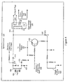
- FIG. 2 is a schematic diagram of the battery charging and isolation circuit 186.
- the battery charging and isolation circuit 186 is configured to receive the supply voltage 148 from the power generation circuit 150, and is adapted to prevent any interruption, decrease, and/or degradation of the supply voltage 148. This assures that the electronic control unit 170 receives the proper 12 volt regulated supply voltage 152 from the voltage regulation circuit 160. This is important because if the electronic control unit does not function properly due to an improper supply voltage level, the engine will fail to run.
- a positive terminal 202 of the starter motor battery 116 such as a 12 volt rechargeable battery, is coupled to the starter motor 110 through the electric starting circuit 120 to provide power to the starter motor, while a negative terminal 210 of the battery is connected to ground.
- Any suitable battery and/or voltage range may be used, depending on the operating characteristics of the starter motor and the voltage rating of the components of the various circuits.
- the supply voltage 148 is coupled to a source terminal of a MOS transistor 216.
- the MOS transistor 216 may be a P-channel enhancement mode vertical DMOS FET, such as part no. ZVP3306A, available from Zetex Semiconductors. Any suitable switching element or transistor may be used.
- the positive terminal of the battery 202 is operatively coupled to the drain terminal of the MOS transistor 216 through a blocking diode 220.
- the blocking diode 220 may prevent current flow from the battery to the MOS transistor 216.
- a bias resistor 224 such as a 470 ohm resistor, couples the source and gate terminals of the MOS transistor 216.
- the gate terminal of the transistor 216 is further coupled to ground through a Zener diode 230.
- the battery 116 may be trickle-charged by the supply voltage 148 through the MOS transistor 216.
- the threshold value of the Zener diode 230 is about 12 volts. In another embodiment, the threshold value of the Zener diode 230 is between about 9 volts and about 12 volts. Any suitable Zener threshold value may be used, which may be based on the voltage rating of the battery 116. For example, the Zener diode 230 may be selected to have a threshold value somewhat less than the voltage rating of the battery, for example between about 1 volt and about 5 volts lower than the maximum battery voltage.
- the voltage at the gate of the MOS transistor 216 is fixed by the Zener diode 230 at its breakdown voltage. If the supply voltage 148 at the source of the MOS transistor 216 should drop enough to cause the Vgs of the device to be insufficient to keep it turned on, the MOS transistor 216 will turn off. In so doing, the battery 116 is disconnected from the supply voltage 148, thus protecting the voltage regulator circuit 160, the electronic control unit 170, and the fuel injection system 180.
- the supply voltage 148 may then rise to full voltage. However, this may turn the MOS transistor 216 on again. Thus, the MOS transistor 216 may cycle on and off.
- the duty cycle of such a waveform may be about 20 milliseconds depending on the RC time constants inherent in the circuit and the battery charging characteristics of the battery 116.
- the cycling of the MOS transistor 216 during battery charging may induce ripple or spikes in the supply voltage 148, but such ripple does not adversely affect the voltage regulator circuit 160, which continues to provide a component voltage 152 to the electronic control unit 170.
- the battery 116 may be trickle-charged.
- the MOS transistor 216 will remain off to prevent interference with the supply voltage 148. Accordingly, the various components of the engine system 100 can function properly, including the electronic control unit 170 and the fuel injection system 180, even though the battery 116 or electric start capability is not operational. In this event, the user may start the engine manually using the recoil system 192.
- FIG. 3 is a schematic diagram of the electric starting circuit 120.
- the positive terminal 202 of the battery 116 is coupled to a first terminal 310 of the starter motor 110 through a normally-open relay switch 304, which, in the illustrated embodiment, is part of an electromechanical relay 316.
- a starter switch 320 which may be a momentary contact switch, is shown as normally-open in the "run" position and indicated as “Run Position - Open.”
- the user depresses the starter switch 320 to the start position. This applies power to the relay 316, which in turn, closes the normally-open relay switch 314, illustrated using dashed lines and indicated as the "Motor Start Position - Momentary Close”.
- the relay switch 304 closes, power is provided to the starter motor 110.
- the user may release the starter switch 320, which then returns to the normally-open or run position.
- Figure 4 is a schematic diagram of the ignition circuit 130.
- the engine 104 rotates, it turns a magnet assembly 404.
- the magnet assembly 404 rotates in proximity with (or within) a current charging armature coil 406.
- the magnet assembly 404 and current charging armature coil 406 function as a magneto to provide the spark to the spark plugs and electrical power to the system.
- the armature coil 406 is coupled to the high voltage transformer coil 136 through a spark ignition capacitor 410.
- High-voltage diodes 416, 418, 420, and 422 rectify the output of the armature coil 406 and provide a rectified output of about 2,000 volts to about 3,000 volts.
- a transistor 430 is controlled via its base terminal by the electronic control unit 170 (ECU 170) (see Figure 1 ) through an ECU spark advance signal 434.
- ECU spark advance signal 434 triggers the transistor 430
- an ignition switch or SCR 440 conducts causing the spark ignition capacitor 410 to discharge, which in turn, creates the spark for the spark plugs through secondary windings 448 of the high voltage transformer 138.
- the ECU 170 works in conjunction with a trigger winding coil 450 to provide proper timing for the ignition spark ignition capacitor 410.
- the ignition circuit 130 may be a commercially available ignition circuit, such as a CDI (capacitive discharge ignition) circuit available from PCRC of Missouri.
- FIG. 5 is a schematic diagram of the power generation circuit 150 and the voltage regulation circuit 160.
- the power generation coil 144 is coupled to a plurality of diodes 510 to provide a full-wave rectified signal.
- the power generation coil 144 in the illustrated embodiment, is inductively coupled to the high voltage transformer coil 136 of the ignition circuit 130. Thus, there may be no direct wiring or physical connection between the power generation circuit 150 and the ignition circuit 130.
- the power generation coil 144 may step down the high-voltage output of the transformer coil 136 by a factor of about 100 to about 200 based on the winding turn ratio between the two coils 136 and 144.
- the stepped-down and rectified signal is at a voltage level to provide the supply voltage 148.
- the supply voltage 148 is also supplied to the battery charging/isolation circuit 186 and the voltage regulation circuit 160.
- a storage capacitor 520 smooths the output ripple, while Zener diode 526 regulates the voltage to the desired supply voltage 148 level.
- the voltage regulation circuit 160 receives the supply voltage 148 from the power generation circuit 150 and provides regulated electrical power for the various electronic components and circuits that control the engine 104.
- the voltage regulation circuit 160 provides the component voltage 152 at about a 12 volt level to the electronic control unit 170, which controls many of the electrical functions of the engine 104, including the fuel injection system 180.
- the voltage regulation circuit 160 includes a bipolar transistor 550 having a base terminal 556 coupled to a Zener diode 560.
- the Zener diode 560 in one embodiment has a breakdown threshold voltage of about 13 volts so that the output of the transistor 550 at an emitter terminal 560 is about 12 volts, which is the component voltage 152 of the above illustrated embodiment.
- any suitable voltage level of the component voltage 152 may be used.
- the power generation circuit 150 and voltage regulation circuit 160 need not be in separate circuits and may be combined. Such a combined power generation or power conditioning circuit may provide the appropriate voltage levels to the circuitry of the engine system 100.
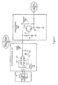
- FIG 6 is a block diagram of the electronic control unit 170 and the fuel injection system 180.
- the electronic control unit 170 of the illustrated embodiment includes a processor 602 and a plurality of sensors to provide data regarding the condition of the engine and environmental parameters. Such sensors, for example, may include a cylinder temperature sensor 610, an air intake temperature sensor 612, an oxygen sensor 614, an engine speed sensor 616, a piston position sensor 618, and other sensors.
- the processor 602 evaluates the data and determines the timing of the spark advance signal 434 (see Figures 1 and 4 ).
- the processor provides injection signals 630 that control when fuel is injected into the engine cylinders.
- the electronic control unit 170 further controls the fuel injection system 180 via the injection signals 630.
- the injection signals 630 electrically activate a plurality of corresponding injector solenoids 640, which provide the mechanical force to inject fuel into the cylinders through cylinder nozzles 644.
Abstract
A control system is adapted to control an internal combustion engine, which has a battery for electric start operation and a mechanical starter for manual start operation. The control system includes a transformer configured to generate a high voltage output for providing a spark, and a power regulation circuit having an input adapted to receive the high voltage output and generate a low voltage supply. A battery charging circuit includes a switching element adapted to receive the low voltage supply and operatively couple the low voltage supply to the battery to charge the battery. The battery charging circuit includes a disconnecting circuitry diode operatively coupled to the switching element so that if a voltage level of the battery falls below a predetermined value, the disconnecting circuitry diode turns off the transistor to electrically disconnect the battery from the low voltage supply and disable the electric start operation. The mechanical starter is configured to start the engine if the battery is insufficiently charged to drive the electric motor to start the engine.
Description
- This disclosure relates to a battery charging and isolation system. In particular, this disclosure relates to a battery charging and isolation circuit for a small internal-combustion engine configured to power lawn and gardening equipment, which has a starter motor, a battery, and control circuitry.
- Some internal-combustion engines, such as small two-cycle engines used to power lawn and gardening equipment may be started by either electrically using a starter motor and a battery, or by using a mechanical device, such as a recoil mechanism. Some engines may include both starting systems. More sophisticated engines have a fuel-injection system, which is typically controlled by control circuitry. Rotation of the engine turns a magneto assembly, which supplies a high-voltage signal to the spark plugs. The high-voltage signal is typically stepped-down and filtered to provide a conditioned supply voltage to the circuitry.
- However, if the control circuitry fails or the conditioned supply voltage is interrupted or otherwise degraded, the engine will not run, typically due to failure of the fuel injection system. The battery that supplies power to the starter motor has a finite life and eventually must be replaced. Such batteries tend to fail on occasion due to the harsh environment in which the devices are used. If the battery does fail, in known systems, such a failure typically interrupts, short-circuits, or otherwise degrades the conditioned supply voltage, thus causing engine failure, even though the other components of the system may be functioning properly. A need exists for effectively removing or isolating a drained or short-circuited battery from the other electrical components of the engine system so that the engine can still be started mechanically.
- According to a first aspect the invention provides a control system for an internal combustion engine having a battery for electric start operation and a mechanical starter for manual start operation, the control system comprising a transformer configured to generate a high voltage output for providing a spark, a power regulation circuit having an input adapted to receive the high voltage output and generate a low voltage supply, and a battery charging circuit having a switching element adapted to receive the low voltage supply and operatively couple the low voltage supply to the battery to charge the battery, the battery charging circuit including disconnecting circuitry operatively coupled to the switching element, wherein if a voltage level of the battery falls below a predetermined threshold value, the disconnecting circuitry turns off the transistor to electrically disconnect the battery from the low voltage supply and disable the battery charging operation, wherein the mechanical starter is configured to start the engine if the battery is insufficiently charged to drive the electric motor to start the engine.
- The battery charging unit may include a blocking diode operatively coupled between an output terminal of the switching element and the battery to prevent reverse current flow from the battery to the switching element.
- A starter motor may be in communication with the battery, wherein a short-circuit between the starter motor and ground causes a voltage level of the battery to fall below the predetermined threshold value of the disconnecting circuitry, and turns off the switching element to operatively disconnect the battery and the starter motor from the low voltage supply.
- The disconnecting circuitry may be a Zener diode. The battery charging circuit may include a biasing resistor having a first end coupled to the low voltage supply, and a second end coupled to a control terminal of the switching element and to a cathode of the Zener diode, the biasing resistor providing a voltage sufficient to maintain the Zener diode in a breakdown mode. The threshold of the Zener diode is preferably between about 1 volt and about 5 volts less than a maximum battery voltage. For typical applications it may for example be between about 9 volts and about 12 volts, or about 12 volts.
- In a further aspect the invention resides in a control system for an internal combustion engine having an electric starter motor powered by a battery, and having a mechanical starter for manual start operation, the control system comprising an ignition circuit configured to generate a high-voltage output for providing a spark, a power conditioning circuit configured to convert the high-voltage output to a low voltage supply, a voltage regulation circuit having an input adapted to receive the low voltage supply and provide a regulated component supply voltage, an electronic control unit adapted to receive the regulated component supply voltage and control functioning of the engine, a battery charging circuit having an electronic switching element adapted to receive the low voltage supply and operatively couple the battery to the low voltage supply to charge the battery, the battery charging circuit including disconnecting circuitry operatively coupled to a base of an electronic switching element, wherein if a voltage level of the battery falls below a predetermined value, the disconnecting circuitry turns off the electronic switching element to electrically disconnect the battery from the low voltage supply and disable battery charging operation, and wherein the mechanical starter is configured to start the engine if the battery is insufficiently charged to drive the electric motor to start the engine.
- In a further aspect the invention resides in a battery isolation circuit for use with a power conditioning circuit for an internal combustion engine, the engine having an electric starter motor powered by a battery and a mechanical starter for manual start operation, the battery isolation circuit comprising a transistor adapted to receive a low voltage supply from the power conditioning circuit and operatively couple the low voltage supply to the battery to charge the battery when the transistor is turned on, disconnecting circuitry operatively coupled to a base of the transistor and to the low voltage supply, wherein if a voltage level of the battery falls below a predetermined threshold value of the disconnecting circuitry, the disconnecting circuitry turns off the transistor to electrically disconnect the battery from the low voltage supply, and wherein the mechanical starter is configured to start the engine if the battery is insufficiently charged.
- Embodiments of the invention are described, by way of example only, with reference to the following drawings in which:
-
Figure 1 is a block diagram of an engine system; -
Figure 2 is a schematic diagram of a battery charge/isolation circuit according to a specific embodiment; -
Figure 3 is a schematic diagram of an electric starting circuit according to a specific embodiment; -
Figure 4 is a schematic diagram of an ignition circuit according to a specific embodiment; -
Figure 5 is a schematic diagram of a power generation circuit and a voltage regulation circuit according to a specific embodiment; and -
Figure 6 is a schematic diagram of an electronic control unit and fuel injection circuit according to a specific embodiment. - The invention is described with reference to the drawings in which like elements are referred to by like numerals. The relationship and function of the various elements of this invention are better understood by the following description. Each aspect so defined may be combined with any other aspect or aspects unless clearly indicated to the contrary.
-
Figure 1 is a block diagram of an internal-combustion engine system 100, including various electronic circuits and components. An internal-combustion engine 104, may be for example, a two-cycle gasoline engine. Theengine 104 may be used in lawn and gardening equipment and outdoor tools, such as line or string trimmers, hedge trimmers, leaf blowers, chain saws, and other small outdoor-type tools. Any suitable internal-combustion engine may be used. - The
engine system 100 includes astarter motor 110 to start theengine 104, astarter motor battery 116 to power thestarter motor 110, and anelectric starting circuit 120 to control the starter motor. Anignition circuit 130 provides a high-voltage output via a high-voltage transformer coil 136 of ahigh voltage transformer 138 to supply a spark to the spark plugs. The high-voltage transformer coil 136 is inductively coupled to apower generation coil 144 of apower generation circuit 150, which may step-down and rectify the high voltage output to generate a reduced rectifiedsupply voltage 148 at about an 18 volt level in one specific embodiment. The 18 volt supply voltage orsupply voltage 148 may have spike or pulse-like waveform because it is derived from transformer coils having currents induced by rotating magnet components. - In the illustrated embodiment, a
voltage regulator circuit 160 receives thesupply voltage 148, and further conditions and filters the signal to provide a 12 volt component supply voltage orcomponent voltage 152, which powers the various electrical components of theengine system 100. For example, thevoltage regulator circuit 160 supplies thecomponent voltage 152 to anelectronic control unit 170, which in turn, controls afuel injection system 180. Thesupply voltage 148 is also supplied to a battery/charging isolation circuit 186, which trickle-charges thestarter motor battery 116. Of course, thepower generation circuit 150 may be configured to provide any suitable voltage level so long as this level is equal to or greater than the voltage rating of thestarter motor battery 116 so that trickle-charging may be performed. - The internal-
combustion engine 104 of the illustrated embodiment is a conventional gasoline engine having a dual-mode starting mechanism. In that regard, theengine 104 has aconventional recoil starter 192, which is configured to rotate the engine flywheel when pulled or cranked by the user so as to start theengine 104. In addition to therecoil starter 192, theengine 104 includes theelectric starter motor 110 to start the engine. Thus, the user may start theengine 104 either manually using therecoil starter 192 or electrically using thestarter motor 110. - Because the above-described circuits are coupled to an internal-
combustion engine 104, which may be adapted for outdoor use or use in challenging environments, such components may be subjected to harsh conditions. Such harsh conditions may include extremes of temperature, precipitation and moisture, shock and vibration, and other conditions that may damage the components or circuitry. Such harsh conditions may also damage thestarter motor battery 116 or may cause a short circuit or open circuit somewhere in theengine system 100. - Although sufficiently harsh conditions may damage one or more critical components so that the
engine 104 will fail to operate, neither thestarter motor battery 116 nor thestarter motor 110 is such a critical component. That is, failure of thestarter motor battery 116 or thestarter motor 110 should not disable theengine 104 because the second system, namely themanual recoil starter 192, may be used to start the engine. Furthermore, once theengine 104 has been started, thepower generation circuit 150 generates the electricity necessary to power the electrical components. In addition to possible battery damage caused by misuse or harsh conditions, in some circumstances, thebattery 116 may become drained or otherwise fail, as such batteries have a finite useful lifetime. For example, thebattery 116 may no longer accept or retain a charge when it reaches the end of its useful life. - In contrast, the
electronic control unit 170 andfuel injection system 180 are critical components, and theengine 104 will not run if these components are disabled or otherwise damaged. For example, theelectronic control unit 170 or thefuel injection system 180 may become disabled if they do not receive the appropriate voltage levels from thevoltage regulation circuit 160, which is dependent on thesupply voltage 148 generated by thepower generation circuit 150. - Because the
starter motor battery 116 is trickle-charged by thesupply voltage 148, and theelectronic control unit 170 indirectly receives power based on the supply voltage 148 (via the voltage regulation circuit 160), a short-circuit or battery failure may cause failure or interruption of the 18volt supply voltage 148, thus disabling theengine 104. Accordingly, the battery charge/isolation circuit 186 is configured to isolate thestarter motor battery 116 from both thepower generation circuit 150 and thevoltage regulation circuit 160, and/or other components of the system should the battery become drained or short-circuited, or otherwise interfere with thesupply voltage 148. -
Figure 2 is a schematic diagram of the battery charging andisolation circuit 186. The battery charging andisolation circuit 186 is configured to receive thesupply voltage 148 from thepower generation circuit 150, and is adapted to prevent any interruption, decrease, and/or degradation of thesupply voltage 148. This assures that theelectronic control unit 170 receives the proper 12 voltregulated supply voltage 152 from thevoltage regulation circuit 160. This is important because if the electronic control unit does not function properly due to an improper supply voltage level, the engine will fail to run. - A
positive terminal 202 of thestarter motor battery 116, such as a 12 volt rechargeable battery, is coupled to thestarter motor 110 through theelectric starting circuit 120 to provide power to the starter motor, while a negative terminal 210 of the battery is connected to ground. Any suitable battery and/or voltage range may be used, depending on the operating characteristics of the starter motor and the voltage rating of the components of the various circuits. - In the illustrated embodiment, the
supply voltage 148 is coupled to a source terminal of aMOS transistor 216. TheMOS transistor 216 may be a P-channel enhancement mode vertical DMOS FET, such as part no. ZVP3306A, available from Zetex Semiconductors. Any suitable switching element or transistor may be used. The positive terminal of thebattery 202 is operatively coupled to the drain terminal of theMOS transistor 216 through a blockingdiode 220. The blockingdiode 220 may prevent current flow from the battery to theMOS transistor 216. Abias resistor 224, such as a 470 ohm resistor, couples the source and gate terminals of theMOS transistor 216. The gate terminal of thetransistor 216 is further coupled to ground through aZener diode 230. Thebattery 116 may be trickle-charged by thesupply voltage 148 through theMOS transistor 216. - If the battery voltage falls below the Zener breakdown threshold (about 12 volts in the illustrated embodiment), or if the
battery 116 or thestarter motor 110 becomes short-circuited to ground, the voltage level at the cathode of theZener diode 230 will fall below the Zener threshold level. This occurs because the source terminal of theMOS transistor 216 will tend to be pulled down toward the battery potential through the conductingMOS transistor 216. In one embodiment, the threshold value of theZener diode 230 is about 12 volts. In another embodiment, the threshold value of theZener diode 230 is between about 9 volts and about 12 volts. Any suitable Zener threshold value may be used, which may be based on the voltage rating of thebattery 116. For example, theZener diode 230 may be selected to have a threshold value somewhat less than the voltage rating of the battery, for example between about 1 volt and about 5 volts lower than the maximum battery voltage. - The voltage at the gate of the
MOS transistor 216 is fixed by theZener diode 230 at its breakdown voltage. If thesupply voltage 148 at the source of theMOS transistor 216 should drop enough to cause the Vgs of the device to be insufficient to keep it turned on, theMOS transistor 216 will turn off. In so doing, thebattery 116 is disconnected from thesupply voltage 148, thus protecting thevoltage regulator circuit 160, theelectronic control unit 170, and thefuel injection system 180. - Once the
MOS transistor 216 turns off, thesupply voltage 148 may then rise to full voltage. However, this may turn theMOS transistor 216 on again. Thus, theMOS transistor 216 may cycle on and off. The duty cycle of such a waveform may be about 20 milliseconds depending on the RC time constants inherent in the circuit and the battery charging characteristics of thebattery 116. The cycling of theMOS transistor 216 during battery charging may induce ripple or spikes in thesupply voltage 148, but such ripple does not adversely affect thevoltage regulator circuit 160, which continues to provide acomponent voltage 152 to theelectronic control unit 170. - During the "on" cycle of the
MOS transistor 216, thebattery 116 may be trickle-charged. Of course, if thebattery 116 experiences a hard failure, or if thestarter motor 110 is short-circuited to ground, theMOS transistor 216 will remain off to prevent interference with thesupply voltage 148. Accordingly, the various components of theengine system 100 can function properly, including theelectronic control unit 170 and thefuel injection system 180, even though thebattery 116 or electric start capability is not operational. In this event, the user may start the engine manually using therecoil system 192. -
Figure 3 is a schematic diagram of theelectric starting circuit 120. Thepositive terminal 202 of thebattery 116 is coupled to afirst terminal 310 of thestarter motor 110 through a normally-open relay switch 304, which, in the illustrated embodiment, is part of anelectromechanical relay 316. Astarter switch 320, which may be a momentary contact switch, is shown as normally-open in the "run" position and indicated as "Run Position - Open." To electrically start theengine 104, the user depresses thestarter switch 320 to the start position. This applies power to therelay 316, which in turn, closes the normally-open relay switch 314, illustrated using dashed lines and indicated as the "Motor Start Position - Momentary Close". When therelay switch 304 closes, power is provided to thestarter motor 110. Once theengine 104 starts, the user may release thestarter switch 320, which then returns to the normally-open or run position. -
Figure 4 is a schematic diagram of theignition circuit 130. As theengine 104 rotates, it turns amagnet assembly 404. Themagnet assembly 404 rotates in proximity with (or within) a currentcharging armature coil 406. Themagnet assembly 404 and currentcharging armature coil 406 function as a magneto to provide the spark to the spark plugs and electrical power to the system. Thearmature coil 406 is coupled to the highvoltage transformer coil 136 through aspark ignition capacitor 410. High-voltage diodes armature coil 406 and provide a rectified output of about 2,000 volts to about 3,000 volts. - A
transistor 430 is controlled via its base terminal by the electronic control unit 170 (ECU 170) (seeFigure 1 ) through an ECUspark advance signal 434. When the ECUspark advance signal 434 triggers thetransistor 430, an ignition switch orSCR 440 conducts causing thespark ignition capacitor 410 to discharge, which in turn, creates the spark for the spark plugs throughsecondary windings 448 of thehigh voltage transformer 138. TheECU 170 works in conjunction with atrigger winding coil 450 to provide proper timing for the ignitionspark ignition capacitor 410. Theignition circuit 130 may be a commercially available ignition circuit, such as a CDI (capacitive discharge ignition) circuit available from PCRC of Missouri. -
Figure 5 is a schematic diagram of thepower generation circuit 150 and thevoltage regulation circuit 160. Thepower generation coil 144 is coupled to a plurality ofdiodes 510 to provide a full-wave rectified signal. Thepower generation coil 144, in the illustrated embodiment, is inductively coupled to the highvoltage transformer coil 136 of theignition circuit 130. Thus, there may be no direct wiring or physical connection between thepower generation circuit 150 and theignition circuit 130. Thepower generation coil 144 may step down the high-voltage output of thetransformer coil 136 by a factor of about 100 to about 200 based on the winding turn ratio between the twocoils supply voltage 148. Thesupply voltage 148 is also supplied to the battery charging/isolation circuit 186 and thevoltage regulation circuit 160. Astorage capacitor 520 smooths the output ripple, whileZener diode 526 regulates the voltage to the desiredsupply voltage 148 level. - The
voltage regulation circuit 160 receives thesupply voltage 148 from thepower generation circuit 150 and provides regulated electrical power for the various electronic components and circuits that control theengine 104. For example, thevoltage regulation circuit 160 provides thecomponent voltage 152 at about a 12 volt level to theelectronic control unit 170, which controls many of the electrical functions of theengine 104, including thefuel injection system 180. In the illustrated embodiment, thevoltage regulation circuit 160 includes abipolar transistor 550 having abase terminal 556 coupled to aZener diode 560. TheZener diode 560 in one embodiment has a breakdown threshold voltage of about 13 volts so that the output of thetransistor 550 at anemitter terminal 560 is about 12 volts, which is thecomponent voltage 152 of the above illustrated embodiment. Depending upon system configuration and the various component voltage requirements, any suitable voltage level of thecomponent voltage 152 may be used. - The
power generation circuit 150 andvoltage regulation circuit 160 need not be in separate circuits and may be combined. Such a combined power generation or power conditioning circuit may provide the appropriate voltage levels to the circuitry of theengine system 100. -
Figure 6 is a block diagram of theelectronic control unit 170 and thefuel injection system 180. Theelectronic control unit 170 of the illustrated embodiment includes aprocessor 602 and a plurality of sensors to provide data regarding the condition of the engine and environmental parameters. Such sensors, for example, may include acylinder temperature sensor 610, an airintake temperature sensor 612, anoxygen sensor 614, an engine speed sensor 616, a piston position sensor 618, and other sensors. Theprocessor 602 evaluates the data and determines the timing of the spark advance signal 434 (seeFigures 1 and4 ). The processor provides injection signals 630 that control when fuel is injected into the engine cylinders. Theelectronic control unit 170 further controls thefuel injection system 180 via the injection signals 630. The injection signals 630 electrically activate a plurality ofcorresponding injector solenoids 640, which provide the mechanical force to inject fuel into the cylinders throughcylinder nozzles 644. - While the invention has been illustrated and described in detail in the drawings and foregoing description, the same is to be considered as illustrative and not restrictive in character, it being understood that only exemplary embodiments have been shown and described and do not limit the scope of the invention in any manner. The illustrative embodiments are not exclusive of each other or of other embodiments not recited herein. Accordingly, the invention also provides embodiments that comprise combinations of one or more of the illustrative embodiments described above. Modifications and variations of the invention as herein set forth can be made without departing from the scope thereof, and, therefore, only such limitations should be imposed as are indicated by the appended claims.
Claims (23)
- A control system for an internal combustion engine having a battery for electric start operation and a mechanical starter for manual start operation, the control system comprising:a transformer configured to generate a high voltage output for providing a spark;a power regulation circuit having an input adapted to receive the high voltage output and generate a low voltage supply; anda battery charging circuit having a switching element adapted to receive the low voltage supply and operatively couple the low voltage supply to the battery to charge the battery, the battery charging circuit including disconnecting circuitry operatively coupled to the switching element, wherein if a voltage level of the battery falls below a predetermined threshold value, the disconnecting circuitry turns off the switching element to electrically disconnect the battery from the low voltage supply and disable the battery charging operation;wherein the mechanical starter is configured to start the engine if the battery is insufficiently charged to drive the electric motor to start the engine.
- The control system of claim 1, wherein the battery charging circuit includes a blocking diode operatively coupled between an output terminal of the switching element and the battery to prevent reverse current flow from the battery to the switching element.
- The control system of claim 1 or 2, further comprising a starter motor in communication with the battery.
- The control system of claim 3, wherein a short-circuit between the starter motor and ground causes a voltage level of the battery to fall below the predetermined threshold value of the disconnecting circuitry, and turns off the switching element to operatively disconnect the battery and the starter motor from the low voltage supply.
- The control system of any preceding claim wherein the disconnecting circuitry is a Zener diode.
- The control system of claim 5, wherein the battery charging circuit includes a biasing resistor having a first end coupled to the low voltage supply, and a second end coupled to a control terminal of the switching element and to a cathode of the Zener diode.
- The control system of claim 6, wherein the biasing resistor provides a voltage sufficient to maintain the Zener diode in a breakdown mode.
- The control system of claim 5, 6 or 7, wherein the threshold value of the Zener diode is about 12 volts.
- The control system of claim 5, 6 or 7, wherein the threshold value of the Zener diode is between about 9 volts and about 12 volts.
- The control system of claim 5, wherein the threshold value of the Zener diode is between about 1 volt and about 5 volts less than a maximum battery voltage.
- A control system for an internal combustion engine having an electric starter motor powered by a battery, and having a mechanical starter for manual start operation, the control system comprising:an ignition circuit configured to generate a high-voltage output for providing a spark;a power conditioning circuit configured to convert the high-voltage output to a low voltage supply;a voltage regulation circuit having an input adapted to receive the low voltage supply and provide a regulated component supply voltage;an electronic control unit adapted to receive the regulated component supply voltage and control functioning of the engine;a battery charging circuit having an electronic switching element adapted to receive the low voltage supply and operatively couple the battery to the low voltage supply to charge the battery;the battery charging circuit including disconnecting circuitry operatively coupled to a base of an electronic switching element, wherein if a voltage level of the battery falls below a predetermined value, the disconnecting circuitry turns off the electronic switching element to electrically disconnect the battery from the low voltage supply and disable battery charging operation; andwherein the mechanical starter is configured to start the engine if the battery is insufficiently charged to drive the electric motor to start the engine.
- The control system of claim 11 wherein the disconnecting circuitry is a Zener diode.
- The control system of claim 11 or 12, wherein the battery charging circuit includes a blocking diode operatively coupled between an output terminal of the electronic switching element and the battery to prevent reverse current flow from the battery to the electronic switching element.
- The control system of claim 11, 12 or 13, wherein a short-circuit between the starter motor and ground causes a voltage level of the battery to fall below the predetermined threshold value of the disconnecting circuitry, and turns off the electronic switching element to operatively disconnect the battery and the starter motor from the low voltage supply.
- The control system of claim 12, wherein the battery charging circuit includes a biasing resistor having a first end coupled to the low voltage supply, and a second end coupled to a gate of the electronic switching element and to a cathode of the Zener diode.
- The control system of claim 15, wherein the biasing resistor provides a voltage sufficient to maintain the Zener diode in a breakdown mode.
- The control system of claim 12, wherein a threshold value of the Zener diode is between about 9 volts and about 12 volts.
- A battery isolation circuit for use with a power conditioning circuit for an internal combustion engine, the engine having an electric starter motor powered by a battery and a mechanical starter for manual start operation, the battery isolation circuit comprising:a transistor adapted to receive a low voltage supply from the power conditioning circuit and operatively couple the low voltage supply to the battery to charge the battery when the transistor is turned on;disconnecting circuitry operatively coupled to a base of the transistor and to the low voltage supply, wherein if a voltage level of the battery falls below a predetermined threshold value of the disconnecting circuitry, the disconnecting circuitry turns off the transistor to electrically disconnect the battery from the low voltage supply; andwherein the mechanical starter is configured to start the engine if the battery is insufficiently charged.
- The control system of claim 18 wherein the disconnecting circuitry is a Zener diode.
- The battery isolation circuit of claim 19, wherein a short-circuit between the starter motor and ground causes the voltage level of the battery to fall below the predetermined threshold value of the Zener diode, which reverse biases the Zener diode and turns off the transistor to operatively disconnect the battery and the starter motor from the low voltage supply.
- The battery isolation circuit of claim 19 or 20, further comprising a biasing resistor having a first end coupled to the low voltage supply, and a second end coupled to a gate of the transistor and to a cathode of the Zener diode.
- The battery isolation circuit of claim 21, wherein the biasing resistor provides a voltage sufficient to maintain the Zener diode in a breakdown mode.
- The battery isolation circuit of any one of claims 18 to 22, further comprising a blocking diode operatively coupled between an output terminal of the transistor and the battery to prevent reverse current flow from the battery to the transistor.
Applications Claiming Priority (1)
| Application Number | Priority Date | Filing Date | Title |
|---|---|---|---|
| US12/115,749 US20090278509A1 (en) | 2008-05-06 | 2008-05-06 | Battery charging and isolation system for gas engine |
Publications (1)
| Publication Number | Publication Date |
|---|---|
| EP2117097A1 true EP2117097A1 (en) | 2009-11-11 |
Family
ID=40933819
Family Applications (1)
| Application Number | Title | Priority Date | Filing Date |
|---|---|---|---|
| EP08253020A Withdrawn EP2117097A1 (en) | 2008-05-06 | 2008-09-12 | Battery charging and isolation system for gas engine |
Country Status (4)
| Country | Link |
|---|---|
| US (1) | US20090278509A1 (en) |
| EP (1) | EP2117097A1 (en) |
| CN (1) | CN101576041A (en) |
| AU (1) | AU2008207652A1 (en) |
Families Citing this family (32)
| Publication number | Priority date | Publication date | Assignee | Title |
|---|---|---|---|---|
| JP2009164415A (en) * | 2008-01-08 | 2009-07-23 | Mitsumi Electric Co Ltd | Semiconductor device |
| US8395278B2 (en) * | 2010-08-05 | 2013-03-12 | GM Global Technology Operations LLC | Method and apparatus for starting an internal combustion engine |
| JP5100804B2 (en) * | 2010-09-13 | 2012-12-19 | 三菱電機株式会社 | Start control unit and start command signal generator for the same |
| US8727233B2 (en) | 2011-10-17 | 2014-05-20 | Champion Power Equipment, Inc. | Pressure spray washer and control |
| US8857138B2 (en) | 2011-11-04 | 2014-10-14 | Briggs & Stratton Corporation | Starter system for an engine |
| US9127658B2 (en) | 2011-11-04 | 2015-09-08 | Briggs & Stratton Corporation | Internal combustion engine including starting system powered by lithium-ion battery |
| US8733072B2 (en) | 2011-11-04 | 2014-05-27 | Briggs & Stratton Corporation | Starter system for an engine |
| US8868813B2 (en) | 2011-12-30 | 2014-10-21 | Bedrock Automation Platforms Inc. | Communications control system with a serial communications interface and a parallel communications interface |
| US9727511B2 (en) | 2011-12-30 | 2017-08-08 | Bedrock Automation Platforms Inc. | Input/output module with multi-channel switching capability |
| US10834820B2 (en) | 2013-08-06 | 2020-11-10 | Bedrock Automation Platforms Inc. | Industrial control system cable |
| US9467297B2 (en) | 2013-08-06 | 2016-10-11 | Bedrock Automation Platforms Inc. | Industrial control system redundant communications/control modules authentication |
| US11967839B2 (en) | 2011-12-30 | 2024-04-23 | Analog Devices, Inc. | Electromagnetic connector for an industrial control system |
| US11144630B2 (en) | 2011-12-30 | 2021-10-12 | Bedrock Automation Platforms Inc. | Image capture devices for a secure industrial control system |
| US8862802B2 (en) | 2011-12-30 | 2014-10-14 | Bedrock Automation Platforms Inc. | Switch fabric having a serial communications interface and a parallel communications interface |
| US9600434B1 (en) | 2011-12-30 | 2017-03-21 | Bedrock Automation Platforms, Inc. | Switch fabric having a serial communications interface and a parallel communications interface |
| US9437967B2 (en) | 2011-12-30 | 2016-09-06 | Bedrock Automation Platforms, Inc. | Electromagnetic connector for an industrial control system |
| US9191203B2 (en) | 2013-08-06 | 2015-11-17 | Bedrock Automation Platforms Inc. | Secure industrial control system |
| US11314854B2 (en) | 2011-12-30 | 2022-04-26 | Bedrock Automation Platforms Inc. | Image capture devices for a secure industrial control system |
| US8971072B2 (en) | 2011-12-30 | 2015-03-03 | Bedrock Automation Platforms Inc. | Electromagnetic connector for an industrial control system |
| US10834094B2 (en) | 2013-08-06 | 2020-11-10 | Bedrock Automation Platforms Inc. | Operator action authentication in an industrial control system |
| KR101360060B1 (en) * | 2012-12-07 | 2014-02-12 | 기아자동차 주식회사 | Method and system for controlling engine start when starter motor of hybrid electric vehicle is failure |
| US10613567B2 (en) | 2013-08-06 | 2020-04-07 | Bedrock Automation Platforms Inc. | Secure power supply for an industrial control system |
| US10130962B2 (en) | 2013-10-10 | 2018-11-20 | Briggs & Stratton Corporation | Wirelessly controlled trigger start and chemical tank change-over for pressure washers |
| JP6960715B2 (en) * | 2014-02-14 | 2021-11-05 | ベドロック・オートメーション・プラットフォームズ・インコーポレーテッド | Safe power supply for industrial control systems |
| WO2015134884A1 (en) | 2014-03-06 | 2015-09-11 | Briggs & Stratton Corporation | Rechargeable battery system for replacement of lead-acid battery |
| US11349323B2 (en) * | 2015-03-06 | 2022-05-31 | Briggs & Stratton, Llc | Lithium-ion battery for engine starting |
| USD795181S1 (en) | 2016-06-15 | 2017-08-22 | Briggs & Stratton Corporation | Battery |
| CN107634644A (en) * | 2017-10-31 | 2018-01-26 | 无锡汉神电气股份有限公司 | A kind of surge mu balanced circuit |
| DE202018100148U1 (en) * | 2018-01-11 | 2019-04-12 | WeightWorks GmbH | Energy storage device, motor vehicle or monitoring system with such an energy storage device and use of such energy storage device |
| JP7024463B2 (en) * | 2018-02-01 | 2022-02-24 | 株式会社Gsユアサ | Management device, power storage device, management method of power storage element |
| US11319915B2 (en) | 2020-06-11 | 2022-05-03 | Kohler Co. | Engine system, and method of starting the engine |
| CN113803183A (en) * | 2020-06-11 | 2021-12-17 | 科勒公司 | Engine system and method for starting engine |
Citations (6)
| Publication number | Priority date | Publication date | Assignee | Title |
|---|---|---|---|---|
| US3217229A (en) * | 1962-05-08 | 1965-11-09 | Lyttleton W Ballard | Alternator current and voltage control |
| GB1149889A (en) * | 1966-02-25 | 1969-04-23 | Mcculloch Corp | Improvements in voltage cut-off circuits |
| US4056765A (en) * | 1975-10-20 | 1977-11-01 | Howard H. Morse | Battery-generator output monitor |
| US6249106B1 (en) * | 2000-09-21 | 2001-06-19 | Delphi Technologies, Inc. | Apparatus and method for maintaining a threshold value in a battery |
| JP2002098032A (en) * | 2000-09-25 | 2002-04-05 | Honda Motor Co Ltd | Power supply device for vehicle |
| DE202004007496U1 (en) * | 2004-05-05 | 2004-07-22 | Kinyanjui, Thama-ini, Dr. | Automatically regulated battery charging circuit that provides overload and return current protection |
Family Cites Families (49)
| Publication number | Priority date | Publication date | Assignee | Title |
|---|---|---|---|---|
| US3786344A (en) * | 1971-10-04 | 1974-01-15 | Motorola Inc | Voltage and current regulator with automatic switchover |
| FR2284037A1 (en) * | 1974-09-09 | 1976-04-02 | Peugeot & Renault | METHOD AND DEVICE FOR CONTROL OF AN ELECTROMAGNETIC INJECTOR |
| IT1051454B (en) * | 1975-12-09 | 1981-04-21 | Fiat Spa | FLOW RATE STABILIZATION PROCEDURE AND DEVICE IN ELECTROMAGNETIC INJECTORS BY CORRELATION BETWEEN OPENING INSTANT AND EXCITATION CURRENT |
| US4082066A (en) * | 1976-05-03 | 1978-04-04 | Allied Chemical Corporation | Modulation for fuel density in fuel injection system |
| US4252098A (en) * | 1978-08-10 | 1981-02-24 | Chrysler Corporation | Air/fuel ratio control for an internal combustion engine using an exhaust gas sensor |
| US4348628A (en) * | 1980-06-20 | 1982-09-07 | Loucks Carl C | Electric motor alternating power supply for vehicles |
| US4479161A (en) * | 1982-09-27 | 1984-10-23 | The Bendix Corporation | Switching type driver circuit for fuel injector |
| US4576135A (en) * | 1984-04-24 | 1986-03-18 | Trw Inc. | Fuel injection apparatus employing electric power converter |
| US4753207A (en) * | 1986-10-30 | 1988-06-28 | Allied Corporation | Low voltage supply control system for fuel injectors |
| US4803417A (en) * | 1986-12-22 | 1989-02-07 | General Motors Corporation | Vehicle battery discharging indicator |
| JP2751174B2 (en) * | 1988-02-01 | 1998-05-18 | 株式会社デンソー | Vehicle charging control device |
| US5245252A (en) * | 1988-11-15 | 1993-09-14 | Frus John R | Apparatus and method for providing ignition to a turbine engine |
| US5065073A (en) * | 1988-11-15 | 1991-11-12 | Frus John R | Apparatus and method for providing ignition to a turbine engine |
| JPH03199667A (en) * | 1989-12-27 | 1991-08-30 | Yamaha Motor Co Ltd | 2-cycle engine air/fuel injection device |
| DE4029794A1 (en) * | 1990-08-18 | 1992-02-20 | Bosch Gmbh Robert | METHOD AND DEVICE FOR CONTROLLING AN ELECTROMAGNETIC CONSUMER |
| US5265022A (en) * | 1990-10-26 | 1993-11-23 | Fuji Heavy Industries Ltd. | Engine protecting system |
| IT1241365B (en) * | 1990-12-21 | 1994-01-10 | Sgs Thomson Microelectronics | PILOTING CIRCUIT FOR INDUCTIVE LOADS, IN PARTICULAR FOR FUEL INJECTORS |
| US5092302A (en) * | 1990-12-26 | 1992-03-03 | Ford Motor Company | Fuel pump speed control by dc-dc converter |
| EP0607030B1 (en) * | 1993-01-12 | 1999-03-24 | SILICONIX Incorporated | PWM multiplexed solenoid driver |
| US5629609A (en) * | 1994-03-08 | 1997-05-13 | Texas Instruments Incorporated | Method and apparatus for improving the drop-out voltage in a low drop out voltage regulator |
| JP3319150B2 (en) * | 1994-05-26 | 2002-08-26 | 株式会社デンソー | Control device for fuel pump for internal combustion engine |
| US5502963A (en) * | 1994-09-15 | 1996-04-02 | Kokusan Denki Co., Ltd. | Power device for driving auxiliary equipment for internal combustion engine |
| JPH08336205A (en) * | 1995-04-07 | 1996-12-17 | Nippon Soken Inc | Battery charger for hybrid vehicle |
| JP3166600B2 (en) * | 1996-03-13 | 2001-05-14 | 国産電機株式会社 | Fuel pump drive for fuel injection system for internal combustion engine |
| JP3830243B2 (en) * | 1997-10-06 | 2006-10-04 | トヨタ自動車株式会社 | Battery power supply |
| US6331744B1 (en) * | 1998-02-10 | 2001-12-18 | Light Sciences Corporation | Contactless energy transfer apparatus |
| CN1316436C (en) * | 1998-10-09 | 2007-05-16 | 丰田自动车株式会社 | Charging device |
| US6439674B1 (en) * | 1999-09-01 | 2002-08-27 | Denso Corporation | Vehicle braking apparatus and vehicle braking method |
| US6575146B1 (en) * | 1999-10-22 | 2003-06-10 | Toyota Jidosha Kabushiki Kaisha | Diagnostic apparatus for an evaporated fuel system, and vehicle control apparatus for a vehicle equipped with the diagnostic apparatus |
| US6700802B2 (en) * | 2000-02-14 | 2004-03-02 | Aura Systems, Inc. | Bi-directional power supply circuit |
| US6493618B2 (en) * | 2000-03-15 | 2002-12-10 | Toyota Jidosha Kabushiki Kaisha | Vehicle control using multiple sensors |
| JP3371889B2 (en) * | 2000-04-17 | 2003-01-27 | トヨタ自動車株式会社 | Vehicle slip control |
| JP3736300B2 (en) * | 2000-06-19 | 2006-01-18 | 株式会社日立製作所 | Automobile and power supply device thereof |
| JP3791314B2 (en) * | 2000-09-14 | 2006-06-28 | 株式会社デンソー | In-vehicle device and service providing system |
| JP2002158041A (en) * | 2000-11-16 | 2002-05-31 | Yazaki Corp | Charging method of battery built in slide door |
| US20030024509A1 (en) * | 2001-02-23 | 2003-02-06 | Matusek Steve M. | Method and apparatus for increasing the delivery of fuel to an engine |
| JP3861704B2 (en) * | 2002-01-31 | 2006-12-20 | 株式会社デンソー | Driving device for cooling fan motor for vehicle |
| US6857918B1 (en) * | 2002-03-28 | 2005-02-22 | Bombardier Recreational Products Inc. | Personal watercraft having a hybrid power source |
| JP4904661B2 (en) * | 2002-11-21 | 2012-03-28 | 株式会社デンソー | Fuel cell system |
| US6966040B2 (en) * | 2003-03-14 | 2005-11-15 | Combustion Dynamics Corp. | Systems and methods for operating an electromagnetic actuator |
| US7317300B2 (en) * | 2003-06-23 | 2008-01-08 | Denso Corporation | Automotive battery state monitor apparatus |
| JP4103713B2 (en) * | 2003-07-18 | 2008-06-18 | 株式会社デンソー | Current detector |
| US20050177288A1 (en) * | 2004-02-06 | 2005-08-11 | Sullivan James D. | Interdependent control of aftermarket vehicle accessories without invasive control connections |
| US7000559B2 (en) * | 2004-05-28 | 2006-02-21 | Daka Research Inc. (Br. Virg. Isl Corp.) Offshoreincorporations Centre | Modularized underwater motive device |
| JP4232693B2 (en) * | 2004-06-08 | 2009-03-04 | 株式会社デンソー | Vehicle power generation control system |
| US7124047B2 (en) * | 2004-09-03 | 2006-10-17 | Eaton Corporation | Mathematical model useful for determining and calibrating output of a linear sensor |
| JP2007064209A (en) * | 2005-08-05 | 2007-03-15 | Fujitsu Ten Ltd | Engine control device, control method, and control system |
| US7696719B2 (en) * | 2006-03-07 | 2010-04-13 | Fujitsu Ten Limited | Power control apparatus, power control method |
| US7612524B2 (en) * | 2006-09-29 | 2009-11-03 | International Truck Intellectual Property Company, Llc | Motor vehicle battery disconnect circuit having electronic disconnects |
-
2008
- 2008-05-06 US US12/115,749 patent/US20090278509A1/en not_active Abandoned
- 2008-08-29 AU AU2008207652A patent/AU2008207652A1/en not_active Abandoned
- 2008-09-12 EP EP08253020A patent/EP2117097A1/en not_active Withdrawn
- 2008-09-27 CN CNA2008101488159A patent/CN101576041A/en active Pending
Patent Citations (6)
| Publication number | Priority date | Publication date | Assignee | Title |
|---|---|---|---|---|
| US3217229A (en) * | 1962-05-08 | 1965-11-09 | Lyttleton W Ballard | Alternator current and voltage control |
| GB1149889A (en) * | 1966-02-25 | 1969-04-23 | Mcculloch Corp | Improvements in voltage cut-off circuits |
| US4056765A (en) * | 1975-10-20 | 1977-11-01 | Howard H. Morse | Battery-generator output monitor |
| US6249106B1 (en) * | 2000-09-21 | 2001-06-19 | Delphi Technologies, Inc. | Apparatus and method for maintaining a threshold value in a battery |
| JP2002098032A (en) * | 2000-09-25 | 2002-04-05 | Honda Motor Co Ltd | Power supply device for vehicle |
| DE202004007496U1 (en) * | 2004-05-05 | 2004-07-22 | Kinyanjui, Thama-ini, Dr. | Automatically regulated battery charging circuit that provides overload and return current protection |
Also Published As
| Publication number | Publication date |
|---|---|
| CN101576041A (en) | 2009-11-11 |
| AU2008207652A1 (en) | 2009-11-26 |
| US20090278509A1 (en) | 2009-11-12 |
Similar Documents
| Publication | Publication Date | Title |
|---|---|---|
| EP2117097A1 (en) | Battery charging and isolation system for gas engine | |
| US10626839B2 (en) | Ignition system for light-duty combustion engine | |
| EP2282046A2 (en) | Combustion and emergency starting control system with auxiliary power | |
| US20130154546A1 (en) | Overvoltage Protection System and Method | |
| WO1999015785A1 (en) | Fuel injected rope-start engine without battery | |
| US20210033036A1 (en) | Engine kill switch and control assembly | |
| EP1691053B1 (en) | Control circuit for capacitor discharge ignition system | |
| US4984543A (en) | Oil pressure interlock switch powered by the engine starter | |
| CN108026889B (en) | Ignition system for light-duty combustion engine | |
| US10408136B2 (en) | Throttle trigger actuated throttle position sensor and engine control module | |
| CN112654782B (en) | Engine ignition control unit for improved engine starting | |
| US10907537B2 (en) | Ignition module with low speed control | |
| US20080257322A1 (en) | Capacitor-discharge ignition system for internal combustion engine | |
| CN110753791A (en) | Magneto ignition system and ignition control system | |
| JP5136743B2 (en) | Non-contact ignition control device for internal combustion engine | |
| CN113748264A (en) | Engine ignition system with multiple ignition events | |
| RU2125763C1 (en) | Generator unit for motor vehicle |
Legal Events
| Date | Code | Title | Description |
|---|---|---|---|
| PUAI | Public reference made under article 153(3) epc to a published international application that has entered the european phase |
Free format text: ORIGINAL CODE: 0009012 |
|
| AK | Designated contracting states |
Kind code of ref document: A1 Designated state(s): AT BE BG CH CY CZ DE DK EE ES FI FR GB GR HR HU IE IS IT LI LT LU LV MC MT NL NO PL PT RO SE SI SK TR |
|
| AX | Request for extension of the european patent |
Extension state: AL BA MK RS |
|
| AKX | Designation fees paid | ||
| REG | Reference to a national code |
Ref country code: DE Ref legal event code: 8566 |
|
| STAA | Information on the status of an ep patent application or granted ep patent |
Free format text: STATUS: THE APPLICATION IS DEEMED TO BE WITHDRAWN |
|
| 18D | Application deemed to be withdrawn |
Effective date: 20100828 |