EP2116867A2 - Optical sensor - Google Patents
Optical sensor Download PDFInfo
- Publication number
- EP2116867A2 EP2116867A2 EP08007360A EP08007360A EP2116867A2 EP 2116867 A2 EP2116867 A2 EP 2116867A2 EP 08007360 A EP08007360 A EP 08007360A EP 08007360 A EP08007360 A EP 08007360A EP 2116867 A2 EP2116867 A2 EP 2116867A2
- Authority
- EP
- European Patent Office
- Prior art keywords
- optical
- optical sensor
- sensor according
- light
- coupling
- Prior art date
- Legal status (The legal status is an assumption and is not a legal conclusion. Google has not performed a legal analysis and makes no representation as to the accuracy of the status listed.)
- Withdrawn
Links
Images

Classifications
-
- G—PHYSICS
- G02—OPTICS
- G02B—OPTICAL ELEMENTS, SYSTEMS OR APPARATUS
- G02B6/00—Light guides; Structural details of arrangements comprising light guides and other optical elements, e.g. couplings
- G02B6/10—Light guides; Structural details of arrangements comprising light guides and other optical elements, e.g. couplings of the optical waveguide type
- G02B6/12—Light guides; Structural details of arrangements comprising light guides and other optical elements, e.g. couplings of the optical waveguide type of the integrated circuit kind
- G02B6/13—Integrated optical circuits characterised by the manufacturing method
- G02B6/138—Integrated optical circuits characterised by the manufacturing method by using polymerisation
-
- B—PERFORMING OPERATIONS; TRANSPORTING
- B29—WORKING OF PLASTICS; WORKING OF SUBSTANCES IN A PLASTIC STATE IN GENERAL
- B29D—PRODUCING PARTICULAR ARTICLES FROM PLASTICS OR FROM SUBSTANCES IN A PLASTIC STATE
- B29D11/00—Producing optical elements, e.g. lenses or prisms
- B29D11/00663—Production of light guides
-
- G—PHYSICS
- G01—MEASURING; TESTING
- G01S—RADIO DIRECTION-FINDING; RADIO NAVIGATION; DETERMINING DISTANCE OR VELOCITY BY USE OF RADIO WAVES; LOCATING OR PRESENCE-DETECTING BY USE OF THE REFLECTION OR RERADIATION OF RADIO WAVES; ANALOGOUS ARRANGEMENTS USING OTHER WAVES
- G01S17/00—Systems using the reflection or reradiation of electromagnetic waves other than radio waves, e.g. lidar systems
- G01S17/02—Systems using the reflection of electromagnetic waves other than radio waves
- G01S17/06—Systems determining position data of a target
- G01S17/08—Systems determining position data of a target for measuring distance only
- G01S17/10—Systems determining position data of a target for measuring distance only using transmission of interrupted, pulse-modulated waves
-
- G—PHYSICS
- G01—MEASURING; TESTING
- G01S—RADIO DIRECTION-FINDING; RADIO NAVIGATION; DETERMINING DISTANCE OR VELOCITY BY USE OF RADIO WAVES; LOCATING OR PRESENCE-DETECTING BY USE OF THE REFLECTION OR RERADIATION OF RADIO WAVES; ANALOGOUS ARRANGEMENTS USING OTHER WAVES
- G01S7/00—Details of systems according to groups G01S13/00, G01S15/00, G01S17/00
- G01S7/48—Details of systems according to groups G01S13/00, G01S15/00, G01S17/00 of systems according to group G01S17/00
- G01S7/481—Constructional features, e.g. arrangements of optical elements
- G01S7/4818—Constructional features, e.g. arrangements of optical elements using optical fibres
-
- G—PHYSICS
- G02—OPTICS
- G02B—OPTICAL ELEMENTS, SYSTEMS OR APPARATUS
- G02B6/00—Light guides; Structural details of arrangements comprising light guides and other optical elements, e.g. couplings
- G02B6/10—Light guides; Structural details of arrangements comprising light guides and other optical elements, e.g. couplings of the optical waveguide type
- G02B6/12—Light guides; Structural details of arrangements comprising light guides and other optical elements, e.g. couplings of the optical waveguide type of the integrated circuit kind
- G02B6/122—Basic optical elements, e.g. light-guiding paths
- G02B6/125—Bends, branchings or intersections
-
- G—PHYSICS
- G02—OPTICS
- G02B—OPTICAL ELEMENTS, SYSTEMS OR APPARATUS
- G02B6/00—Light guides; Structural details of arrangements comprising light guides and other optical elements, e.g. couplings
- G02B6/24—Coupling light guides
- G02B6/26—Optical coupling means
- G02B6/30—Optical coupling means for use between fibre and thin-film device
- G02B6/305—Optical coupling means for use between fibre and thin-film device and having an integrated mode-size expanding section, e.g. tapered waveguide
-
- G—PHYSICS
- G02—OPTICS
- G02B—OPTICAL ELEMENTS, SYSTEMS OR APPARATUS
- G02B6/00—Light guides; Structural details of arrangements comprising light guides and other optical elements, e.g. couplings
- G02B6/10—Light guides; Structural details of arrangements comprising light guides and other optical elements, e.g. couplings of the optical waveguide type
- G02B6/12—Light guides; Structural details of arrangements comprising light guides and other optical elements, e.g. couplings of the optical waveguide type of the integrated circuit kind
- G02B2006/12035—Materials
- G02B2006/12069—Organic material
- G02B2006/12071—PMMA
-
- G—PHYSICS
- G02—OPTICS
- G02B—OPTICAL ELEMENTS, SYSTEMS OR APPARATUS
- G02B6/00—Light guides; Structural details of arrangements comprising light guides and other optical elements, e.g. couplings
- G02B6/10—Light guides; Structural details of arrangements comprising light guides and other optical elements, e.g. couplings of the optical waveguide type
- G02B6/12—Light guides; Structural details of arrangements comprising light guides and other optical elements, e.g. couplings of the optical waveguide type of the integrated circuit kind
- G02B2006/12133—Functions
- G02B2006/12147—Coupler
-
- G—PHYSICS
- G02—OPTICS
- G02B—OPTICAL ELEMENTS, SYSTEMS OR APPARATUS
- G02B6/00—Light guides; Structural details of arrangements comprising light guides and other optical elements, e.g. couplings
- G02B6/10—Light guides; Structural details of arrangements comprising light guides and other optical elements, e.g. couplings of the optical waveguide type
- G02B6/14—Mode converters
-
- G—PHYSICS
- G02—OPTICS
- G02B—OPTICAL ELEMENTS, SYSTEMS OR APPARATUS
- G02B6/00—Light guides; Structural details of arrangements comprising light guides and other optical elements, e.g. couplings
- G02B6/24—Coupling light guides
- G02B6/36—Mechanical coupling means
- G02B6/3628—Mechanical coupling means for mounting fibres to supporting carriers
- G02B6/3632—Mechanical coupling means for mounting fibres to supporting carriers characterised by the cross-sectional shape of the mechanical coupling means
- G02B6/3636—Mechanical coupling means for mounting fibres to supporting carriers characterised by the cross-sectional shape of the mechanical coupling means the mechanical coupling means being grooves
-
- G—PHYSICS
- G02—OPTICS
- G02B—OPTICAL ELEMENTS, SYSTEMS OR APPARATUS
- G02B6/00—Light guides; Structural details of arrangements comprising light guides and other optical elements, e.g. couplings
- G02B6/24—Coupling light guides
- G02B6/36—Mechanical coupling means
- G02B6/3628—Mechanical coupling means for mounting fibres to supporting carriers
- G02B6/3648—Supporting carriers of a microbench type, i.e. with micromachined additional mechanical structures
- G02B6/3652—Supporting carriers of a microbench type, i.e. with micromachined additional mechanical structures the additional structures being prepositioning mounting areas, allowing only movement in one dimension, e.g. grooves, trenches or vias in the microbench surface, i.e. self aligning supporting carriers
-
- G—PHYSICS
- G02—OPTICS
- G02B—OPTICAL ELEMENTS, SYSTEMS OR APPARATUS
- G02B6/00—Light guides; Structural details of arrangements comprising light guides and other optical elements, e.g. couplings
- G02B6/24—Coupling light guides
- G02B6/36—Mechanical coupling means
- G02B6/3628—Mechanical coupling means for mounting fibres to supporting carriers
- G02B6/3684—Mechanical coupling means for mounting fibres to supporting carriers characterised by the manufacturing process of surface profiling of the supporting carrier
- G02B6/3696—Mechanical coupling means for mounting fibres to supporting carriers characterised by the manufacturing process of surface profiling of the supporting carrier by moulding, e.g. injection moulding, casting, embossing, stamping, stenciling, printing, or with metallic mould insert manufacturing using LIGA or MIGA techniques
Definitions
- the present invention relates to an optical sensor according to the preamble of claim 1.
- Generic optical sensors for detecting objects in a surveillance area are known for a variety of applications and have the following components: a transmitting unit for emitting light, a receiving unit for receiving light, a transmitting optics for guiding light into the surveillance area and a receiving optics for Passing light coming from the surveillance area to the receiving unit.
- it may be light sensors, triangulation sensors, retro-reflective sensors or electro-optical distance measuring devices based on the transit time principle.
- Optical couplings are known, for example, in the field of telecommunications and have a coupling body on or in which at least one light-guiding region and connecting regions for components to be connected are formed.
- reference pulses are coupled out of the laser beam path, which have a lower height compared to the measuring pulses, but in their pulse shape otherwise as well as possible to match the measuring pulses.
- a pulsed laser diode emits a sequence of identical pulses for each measurement.
- the laser power is coupled into two fibers, typically accounting for 80% of the power on a main channel and 20% of the power on a reference channel.
- the light in the main channel is then directed to a target object and reflected back from there.
- By comparing the reflected Beam with the reference beam can be closed to the duration for the outward and return path of the light and over this to the distance of the target object.
- a clarification of the results can be achieved when averaging over the results of the pulse sequence.
- the measuring and the reference pulses should contain as much as possible the same distribution of light modes.
- This aspect is of particular importance, since laser diodes are usually used as light sources which radiate inhomogeneously over their active area in general. In order to achieve a more homogeneous distribution of the light modes, diffusers or long, conventional optical waveguides are usually used. Due to a large number of reflections, the desired modem compound is produced.
- beam splitters For coupling and decoupling of the laser radiation, for example of additional light sources, beam splitters have hitherto been used in the prior art. These are mechanically treated, for example suitably ground glass fibers, which are glued together.
- electro-optical distance measuring devices which evaluate a pulse transit time usually attenuate the measuring pulses in a defined manner, a complicated mechanical diaphragm, in particular a graduated filter arranged on a rotatable wheel, being frequently used for this.
- a shaping of the beam has hitherto been possible only with considerable mechanical and optical effort, glass fibers also being used here, for example.
- the optical sensor of the type specified above is further developed in that the transmitting optics and / or the receiving optics for connecting optical components have at least one optical coupling, that the optical coupling has a coupling body formed from a first plastic material, on or in the at least one Lichtleit Scheme and connection areas for components to be connected are formed, and that in the coupling body on a first form side, a first recess profile is impressed, which is at least partially filled with a transparent second plastic material to form the Lichtleit Schemee.
- a depression profile is thermally impressed into a mold side of a first half-shell made of a first thermoplastic material with an embossing tool. Furthermore, to form the light-guiding regions, the depression profile is at least partially filled with a transparent second thermoplastic material. In addition, the mold side of the first half-shell is at least partially covered with a second half-shell.
- the optical coupling is used for conducting analog light signals in electro-optical distance measuring devices, in particular according to the transit time principle.
- Another core idea of the invention can be considered to use a stamping method as a simple production technique for the optical couplings to be used.
- the first significant advantage of the invention can be considered that with the embossing technique and variable embossing depths are possible.
- structures can be created that, for example, taper in two dimensions.
- the Einkoppeleffizienz and the variability of the beam shaping can be significantly improved.
- another advantage is that true two-dimensional beam shaping is possible. For example, a beam profile which is initially rectangular in the coupling-in region can be transferred to round beam profiles in the region of the coupling-out.
- the present invention provides an optical sensor with an optical coupling, which is particularly simple and inexpensive to manufacture and in which particularly good properties are achieved with regard to the mode mixture.
- the transmitting unit can basically be any radiation or light source. Particular preference is given to using LEDs or laser diodes.
- the receiving unit basically have known light or radiation detectors.
- semiconductor photodetectors are used.
- optical couplings which are produced according to the embossing method described above, in electro-optical distance measuring devices the analog light signals are routed and possibly manipulated.
- any optical components can be connected to the optical coupling.
- radiation sources, detectors and optical fibers can be connected to the optical couplings.
- the optical coupling for providing a defined optical interface has a cover which at least partially covers the first mold side.
- the cover completely covers at least the light-guiding regions, in order to protect them against soiling, via which light can be coupled out. This cover accordingly provides both mechanical and optical protection.
- the coupling body can have a first half-shell, on which the first mold side is formed, and, in addition, a second half-shell, through which the cover is formed.
- the cover is formed by a, applied to the first form side, in particular glued foil.
- a second depression profile is embossed in the second half-shell on a second mold side.
- this second depression profile in the second half shell the greatest possible design freedom exists, so that the variability of the beam shaping can be increased even further by this measure.
- the second depression profile corresponds in mirror image to the first depression profile.
- the beam cross sections of the light guide regions thus consist of the first and the second depression profile. In principle, apart from the material of the first half shell and the second half shell of the thermal deformability, no further requirement.
- first half shell and / or the second half shell are particularly preferably formed from a transparent first plastic material.
- first half-shell and / or the second half-shell may be formed of PMMA.
- the second half-shell can also be formed from a different material than the first half-shell.
- both shells are particularly preferably made of the same material.
- first and / or the second half-shell is made of a transparent plastic material is particularly preferred in view of the light-guiding properties of the Lichtleit Schemee when the second transparent plastic material with which the first recess profile and the second recess profile are at least partially filled, a lower refractive index has as the first transparent plastic material from which the first half-shell and / or the second half-shell are formed.
- At least one receptacle for an optical fiber to be connected is formed in the coupling body. If the optical coupling is used in a distance measuring device according to the transit time principle, preferably at least one receptacle for a measuring fiber and a reference fiber is present.
- At least one receptacle for a laser diode to be connected is expediently formed at a coupling end of the optical coupling.
- the receptacles for optical fibers to be connected or laser diodes to be connected can advantageously be formed by the first recessed profile and / or the second recessed profile. Further production steps are then not necessary.
- the Lichtleit Scheme or Lichtleit Schemee at least one branch for splitting the laser beams or for coupling the radiation of a second radiation source.
- the above-described method moreover makes it possible to produce optical couplings in which the light-guiding region or the light-guiding regions have a specifically adapted, in particular variable, cross-section in their direction of extent exhibit. This is a particularly important property of the optical coupling and the method described above, since this feature significantly increases the variability and adaptability of the optical beam guidance.
- the light-guiding regions can at least partially have a round or elliptical cross-section.
- the generally rectangular radiating surface of a laser diode at least partially square or rectangular cross sections of the light-guiding regions may be expedient.
- an elliptical cross section may also be advantageous.
- the light-conducting regions advantageously have a round or square cross-section with regard to the most effective possible coupling-out or coupling-in of the radiation.
- optical waveguide region or the waveguide regions are tapered or tapered with increasing distance from a coupling end.
- sensors with optical couplings are possible in which the extent of a light-guiding region changes in its direction of extent in both spatial directions transverse to the direction of extent.
- a coupling element is also provided for receiving a laser diode in the region of at least one coupling-in end.
- This may be a simple injection-molded part, which is connected to the coupling body, for example, locked therein, and in which a laser diode to be connected can be positively received.
- a lens in particular a cylindrical lens, be integrated, with which the emerging from the laser diode radiation can be suitably passed to the coupling end of the corresponding Lichtleit Schemes in the coupling body and directed. In this way coupling losses can be reduced.
- a vertical over-radiation of an end face of a light-conducting region can be reduced and, in addition, the beam divergence can be reduced so that it is as small as possible to an acceptance angle of the light-guiding region.
- a further improvement consists in that said coupling element has an anti-twist device for the laser diode.
- this may be a non-rotationally symmetrical design of the receptacle for the laser diode in the coupling body, so that twisting of the laser diode used in the coupling body is not possible.
- this coupling element itself be adjustable with respect to the coupling element, for example by means of screws.
- this coupling element can be glued to the coupling body, wherein an adjustment must be carried out before the curing of the adhesive bond.
- a heating element in particular a resistance wire, is provided on at least one light-guiding region, with which a weakening of the light to be transmitted can take place up to 30 dB without a mechanical attenuator.
- the optical couplings produced by the method described above can be used particularly well for mixing light modes of the laser radiation.
- the radiation distribution is particularly fast, typically already after about 4 cm homogenized well over the cross section of the Lichtleit Schemee.
- the optical coupling can be used as an optical coupling device between at least one laser and a further optical component, in particular at least one optical fiber.
- analogue light pulses into measuring and reference pulses.
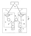
- optical sensor 100 An embodiment of an optical sensor 100 according to the invention will be described with reference to FIG Fig. 7 explained.
- Light emitted by the transmitting unit 13 is split by the coupling 10 onto a measuring fiber 84 and a reference fiber 82.
- Light emerging from the measuring fiber 84 is radiated onto an optical system 15 shown schematically here, which directs the light 17 into a monitoring area 18.
- an optical system 15 shown schematically here, which directs the light 17 into a monitoring area 18.
- a transmitting optical system 16 is formed which guides the light 17 from the transmitting unit 13 into the monitoring area 18.
- optical coupling 11 From an object 19 in the monitoring area 18, light 21 is reflected back and / or backscattered and then passes to an optics 24 shown here schematically.
- the light 21 is subsequently coupled into a glass fiber 23, which is connected to a further optical coupling 11.
- An output of this optical coupling 11 is connected via a further optical fiber 27 to a receiving unit 25 formed by a photodetector.
- another terminal of the optical fiber 24 is connected to the optical coupling 11.
- the optical system 24, the optical fibers 23, 27 and the optical coupling 11 accordingly form a receiving optical unit 22 which directs the light 21 coming from the monitoring area 18 onto the receiving unit 25.
- the optical coupling 11 accordingly serves to conduct both reference pulses via the optical fiber 24 to the receiving unit 25 as well as measurement pulses via the optical fiber 23 to the receiving unit 25.
- pulses supplied by the transmitting unit 13 can be divided into measuring pulses and reference pulses with the aid of the optical coupling 10, which differ substantially only in their height, but not in their shape, due to the particularly effective mixture of modes in the optical coupling 10.
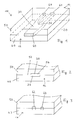
- a first embodiment of an optical coupling 10, as used in an optical sensor according to the invention is, with reference to the FIGS. 1 to 4 explained. Equivalent components are given the same reference numerals in all figures.
- the optical coupling 10 has, as an essential component, a coupling body 20 of a first half-shell 40 and a second half-shell 50.
- the first half shell 40 and the second half shell 50 are each made of a PMMA base material, ie a transparent thermoplastic material.
- An inside or form side 42 of the first half-shell has a recess profile 44, which was thermally impressed there by means of the method described above and a suitable embossing tool.
- a mirror-image-like depression profile 54 is thermally impressed.
- a Lichtleit Geneva is defined.
- the resulting cavities are at least partially, but preferably completely, filled with a lower refractive plastic.
- the first half-shell 40 and the second half-shell 50 are then assembled.
- any optical fiber fibers to be connected may already be inserted into receiving areas provided by the depression profiles 44, 54. In principle, however, this can also take place only after the half shells 40, 50 have been put together.
- a connection region 60 for example for a laser diode 90, is provided. That in the FIGS. 1 and 4 embodiment shown has a Lichtleit Scheme 30 with a branch 36 on. From a portion 38 of the Lichtleit Schemes 30, in which radiation of a laser diode 90 is coupled, accordingly divides the Lichtleit Scheme 30 at the junction 36 in the light guides 32, 34.
- the light-guiding region 30 tapers from the coupling end to the coupling-out end in the in Fig. 4 shown, ie the extension of the light guides 32, 34 in the z-direction is smaller than that of the area 38.
- the Lichtleit Scheme 30 but also tapers in the y-direction, ie in the direction perpendicular to the plane.
- the room seals are in Fig. 4 indicated by a coordinate system 95.
- the region 38 of the Lichtleit Scheme 30 has a substantially rectangular cross-section. This is especially true of the Figures 1 and 2 seen.
- the receiving areas 62, 64 for the optical fibers 82, 84 to be introduced or inserted there have a substantially square cross-section, the receptacle 64, which can receive a measuring fiber 84 of an electro-optical distance measuring device according to the invention, having a larger cross section as the receptacle 62, which serves to receive a reference fiber 82.
- the side lengths of the rectangular entrance surface and the square exit surfaces are on the order of a few 0.1 mm.
- the receptacles 62, 64 are essentially trench-shaped structures or depressions in which the fibers, that is to say the reference fiber 82 and the measuring fiber 84, can be positioned without adjustment.
- FIGS. 1 to 4 illustrated embodiment thus serves as an optical beam splitter for an electro-optical distance measuring device according to the transit time principle.
- FIGS. 5 and 6 A second variant of an optical coupling 10 is in the FIGS. 5 and 6 shown.
- Fig. 5 is a view of the coupling end 12 of the optical coupling 10th
- Fig. 6 shows the Auskoppelende 14 of this optical coupling 10th
- the course of the light guide regions corresponds in the embodiment of the FIGS. 5 and 6 essentially the in Fig. 4 for the first embodiment shown situation.
- the spatial dimensions of the cross sections are again a few 0.1 mm.
- the optical couplings 10 shown in the figures for example, about 50% of an irradiated laser radiation can be coupled into the main channel, that is to say into the measuring fiber 84. For example, only a few percent are injected into the reference fiber 82.
- the branch 36 is made relatively sharp. A rounding leads to a deterioration of the reference decoupling.
- the measuring fiber 84 and the reference fiber 82 are stuck, for example, two millimeters deep in the coupling body 20th
- the present invention provides a novel optical sensor with an optical coupling.
- the optical couplings described here are particularly suitable for applications in optical sensors in general and in particular for those applications in which a targeted beam shaping is necessary. Particular advantages can be achieved here with very small structures, if previously known tool technologies, such as injection molding, do not lead to success.
- these can optical couplings are used according to the invention for electro-optical distance measuring devices according to the transit time principle, in which for the provision of comparable optical pulses, a mode mixture is to take place. Therefore, the optical coupling according to the invention can serve in particular as an optical beam splitter or splitter.
- Compared to previously known technologies such as optical printed circuit boards or simple butt coupling of two fibers side by side can be achieved with the invention significantly improved coupling efficiencies, significantly improved mixing of the individual modes and also a significantly improved reliability of production.
- the good coupling-out efficiency of the reference channel after mode mixing is also significant. Compared to the technology of optical circuit boards also higher numerical apertures can be achieved during coupling and decoupling.
- the hot embossing technology allows overall three-dimensional beam paths within the coupling body and high numerical apertures can be achieved by a large freedom of choice of the material pairings.
- the general objective in the mentioned distance measuring devices according to the transit time principle to couple the highest possible proportion of the light into a measuring fiber and a small defined part in a, in particular shorter, reference fiber, is thus implemented particularly reliably in the optical coupling.
- the same step index fiber can be used, for example, 100 microns in diameter.
- a plastic part can be provided by the optical couplings described here, in which both fibers can be coupled easily and in particular without adjustment.
- the laser diode is also connected without active adjustment with the optical coupling. Since mechanical tolerances of laser diodes are generally comparatively large, it is equally possible to provide suitable adjustment means for the active adjustment of a laser diode.
- the optical couplings described here can basically be operated in a wide temperature range, for example, from -20 to + 75 ° C.
Abstract
Description
Die vorliegende Erfindung betrifft einen optischen Sensor nach dem Oberbegriff des Anspruchs 1.The present invention relates to an optical sensor according to the preamble of
Gattungsgemäße optische Sensoren zum Nachweis von Objekten in einem Überwachungsbereich sind für eine Vielzahl von Anwendungen bekannt und weisen folgende Komponenten auf: eine Sendeeinheit zum Aussenden von Licht, eine Empfangseinheit zum Empfangen von Licht, eine Sendeoptik zum Leiten von Licht in den Überwachungsbereich und eine Empfangsoptik zum Leiten von aus dem Überwachungsbereich kommendem Licht auf die Empfangseinheit.Generic optical sensors for detecting objects in a surveillance area are known for a variety of applications and have the following components: a transmitting unit for emitting light, a receiving unit for receiving light, a transmitting optics for guiding light into the surveillance area and a receiving optics for Passing light coming from the surveillance area to the receiving unit.
Beispielsweise kann es sich um Lichttaster, Triangulationssensoren, Reflexionslichtschranken oder auch um elektrooptische Entfernungsmessgeräte nach dem Laufzeitprinzip handeln.For example, it may be light sensors, triangulation sensors, retro-reflective sensors or electro-optical distance measuring devices based on the transit time principle.
Optische Kupplungen sind beispielsweise aus dem Bereich der Telekommunikation bekannt und weisen einen Kupplungskörper auf, an oder in dem mindestens ein Lichtleitbereich und Anschlussbereiche für anzuschließende Komponenten gebildet sind.Optical couplings are known, for example, in the field of telecommunications and have a coupling body on or in which at least one light-guiding region and connecting regions for components to be connected are formed.
Bei elektrooptischen Entfernungsmessgeräten, insbesondere solchen, bei denen eine Pulslaufzeit zur Entfernungsbestimmung herangezogen wird, werden aus dem Laserstrahlengang Referenzpulse ausgekoppelt, die im Vergleich zu den Messpulsen eine geringere Höhe aufweisen, in ihrer Pulsform ansonsten aber möglichst gut mit den Messpulsen übereinstimmen sollen.In electro-optical distance measuring devices, in particular those in which a pulse transit time is used to determine the distance, reference pulses are coupled out of the laser beam path, which have a lower height compared to the measuring pulses, but in their pulse shape otherwise as well as possible to match the measuring pulses.
Bei diesem Prinzip der Distanzmessung sendet eine gepulste Laserdiode für jede Messung eine Abfolge gleicher Pulse aus. Die Laserleistung wird in zwei Fasern eingekoppelt, wobei typischerweise 80% der Leistung auf einen Hauptkanal und 20% der Leistung auf einen Referenzkanal entfallen. Das Licht im Hauptkanal wird sodann auf ein Zielobjekt gerichtet und von dort zurückreflektiert. Durch Vergleich des reflektierten Strahls mit dem Referenzstrahl kann auf die Zeitdauer für den Hin- und Rückweg des Lichts und hierüber auf die Distanz des Zielobjekts geschlossen werden. Eine Präzisierung der Ergebnisse kann dabei erzielt werden, wenn über die Ergebnisse der Pulsfolge gemittelt wird.In this principle of distance measurement, a pulsed laser diode emits a sequence of identical pulses for each measurement. The laser power is coupled into two fibers, typically accounting for 80% of the power on a main channel and 20% of the power on a reference channel. The light in the main channel is then directed to a target object and reflected back from there. By comparing the reflected Beam with the reference beam can be closed to the duration for the outward and return path of the light and over this to the distance of the target object. A clarification of the results can be achieved when averaging over the results of the pulse sequence.
Hierzu sollten die Mess- und die Referenzpulse möglichst dieselbe Verteilung von Lichtmoden enthalten. Diesem Aspekt kommt besondere Bedeutung zu, da üblicherweise Laserdioden als Lichtquellen verwendet werden, die über ihre aktive Fläche im Allgemeinen inhomogen abstrahlen. Um eine homogenere Verteilung der Lichtmoden zu erzielen, werden üblicherweise Diffusoren oder lange, konventionelle Lichtwellenleiter eingesetzt. Durch eine Vielzahl von Reflexionen kommt es dabei zur gewünschten Modemmischung. Zum Ein- und Auskoppeln der Laserstrahlung, beispielsweise von zusätzlichen Lichtquellen, werden im Stand der Technik bisher Strahlteiler eingesetzt. Hierbei handelt es sich um mechanisch behandelte, beispielsweise geeignet angeschliffene Glasfasern, die miteinander verklebt werden.For this purpose, the measuring and the reference pulses should contain as much as possible the same distribution of light modes. This aspect is of particular importance, since laser diodes are usually used as light sources which radiate inhomogeneously over their active area in general. In order to achieve a more homogeneous distribution of the light modes, diffusers or long, conventional optical waveguides are usually used. Due to a large number of reflections, the desired modem compound is produced. For coupling and decoupling of the laser radiation, for example of additional light sources, beam splitters have hitherto been used in the prior art. These are mechanically treated, for example suitably ground glass fibers, which are glued together.
Um vergleichbare Pulse zu erhalten, werden bei elektrooptischen Entfernungsmessgeräten, die eine Pulslaufzeit auswerten, die Messpulse üblicherweise definiert abgeschwächt, wobei hierfür bisher häufig eine aufwendige mechanische Blende, insbesondere ein auf einem drehbaren Rad angeordnetes Verlaufsfilter eingesetzt werden. Eine Formung des Strahls ist bisher nur mit erheblichem mechanischem und optischem Aufwand möglich, wobei auch hier beispielsweise Glasfasern verwendet werden.In order to obtain comparable pulses, electro-optical distance measuring devices which evaluate a pulse transit time usually attenuate the measuring pulses in a defined manner, a complicated mechanical diaphragm, in particular a graduated filter arranged on a rotatable wheel, being frequently used for this. A shaping of the beam has hitherto been possible only with considerable mechanical and optical effort, glass fibers also being used here, for example.
Die erwähnten Diffusoren erzielen aber nur sehr eingeschränkt die gewünschte Wirkung der Modenmischung und der Prozess ist auch für eine Serienfertigung nur sehr eingeschränkt reproduzierbar.However, the diffusers mentioned achieve only very limited the desired effect of the mode mixture and the process is only very limited reproducible for mass production.
Weiterhin ist der Einsatz von Strahlteilern als auch von anderen Lichtwellenleiter-Lösungen sehr teuer. Lediglich in sehr großen Stückzahlen eingesetzte Typen können zu vertretbaren Preisen bezogen werden. Die dabei zum Einsatz kommenden Glasfasern eignen sich aber nur sehr eingeschränkt für den Bau der oben erwähnten optischen Entfernungsmessgeräte. Sodann sind die üblicherweise eingesetzten Blenden relativ aufwendig und ebenfalls teuer. Darüber hinaus sind die benötigten Blenden nur schwer zu beschaffen.Furthermore, the use of beam splitters and other optical fiber solutions is very expensive. Only types used in large quantities can be purchased at reasonable prices. However, the glass fibers used in this case are only very limited for the construction of the above-mentioned optical distance measuring devices. Then the panels commonly used are relatively expensive and also expensive. In addition, the required panels are difficult to obtain.
Schließlich ist eine Strahlformung mit Hilfe von Glasfasern nur jeweils durch gezielte Fertigung dieser Glasfasern in Handarbeit möglich, was ebenfalls hohe Kosten nach sich zieht.Finally, a beam shaping by means of glass fibers only by targeted production of these glass fibers by hand is possible, which also entails high costs.
Als eine Aufgabe der Erfindung kann angesehen werden, einen optischen Sensor zum Nachweis von Objekten in einem Überwachungsbereich zu schaffen, bei welchem für die Sendeoptik und/oder die Empfangsoptik ein vereinfachter und/oder kostengünstigerer Aufbau erzielt wird.It can be regarded as an object of the invention to provide an optical sensor for detecting objects in a surveillance area, in which a simplified and / or more cost-effective construction is achieved for the transmitting optics and / or the receiving optics.
Diese Aufgabe wird erfindungsgemäß durch den optischen Sensor mit den Merkmalen des Anspruchs 1 gelöst.This object is achieved by the optical sensor with the features of
Der optische Sensor der oben angegebenen Art ist erfindungsgemäß dadurch weitergebildet, dass die Sendeoptik und/oder die Empfangsoptik zum Verbinden von optischen Komponenten mindestens eine optische Kupplung aufweist, dass die optische Kupplung einen aus einem ersten Kunststoffmaterial gebildeten Kupplungskörper aufweist, an oder in dem mindestens ein Lichtleitbereich und Anschlussbereiche für anzuschließende Komponenten gebildet sind, und dass in dem Kupplungskörper an einer ersten Formseite ein erstes Vertiefungsprofil eingeprägt ist, welches zum Bilden der Lichtleitbereiche wenigstens teilweise mit einem transparenten zweiten Kunststoffmaterial verfüllt ist.According to the invention, the optical sensor of the type specified above is further developed in that the transmitting optics and / or the receiving optics for connecting optical components have at least one optical coupling, that the optical coupling has a coupling body formed from a first plastic material, on or in the at least one Lichtleitbereich and connection areas for components to be connected are formed, and that in the coupling body on a first form side, a first recess profile is impressed, which is at least partially filled with a transparent second plastic material to form the Lichtleitbereiche.
Bei einem Verfahren zur Herstellung einer solchen optischen Kupplung wird in eine Formseite einer ersten Halbschale aus einem ersten thermoplastischen Kunststoff mit einem Prägewerkzeug thermisch ein Vertiefungsprofil eingeprägt. Weiterhin wird zum Bilden der Lichtleitbereiche das Vertiefungsprofil wenigstens teilweise mit einem transparenten zweiten thermoplastischen Kunststoffmaterial verfüllt. Außerdem wird die Formseite der ersten Halbschale wenigstens teilweise mit einer zweiten Halbschale abgedeckt.In a method for producing such an optical coupling, a depression profile is thermally impressed into a mold side of a first half-shell made of a first thermoplastic material with an embossing tool. Furthermore, to form the light-guiding regions, the depression profile is at least partially filled with a transparent second thermoplastic material. In addition, the mold side of the first half-shell is at least partially covered with a second half-shell.
Gemäß einem weiteren Aspekt der Erfindung wird die optische Kupplung zum Leiten von analogen Lichtsignalen bei elektrooptischen Entfernungsmessgeräten, insbesondere nach dem Laufzeitprinzip, verwendet.According to a further aspect of the invention, the optical coupling is used for conducting analog light signals in electro-optical distance measuring devices, in particular according to the transit time principle.
Bevorzugte Ausgestaltungen des optischen Sensors sind Gegenstand der abhängigen Ansprüche und werden außerdem in der folgenden Beschreibung, insbesondere mit Bezug auf die beigefügten Figuren, erläutert.Preferred embodiments of the optical sensor are the subject matter of the dependent claims and are also explained in the following description, in particular with reference to the accompanying figures.
Als erster Kerngedanke der Erfindung kann angesehen werden, für die spezifische Aufgabenstellung bei optischen Sensoren und insbesondere bei elektrooptischen Entfernungsmessgeräten, die eine Pulslaufzeit auswerten, zur Ein- und Auskopplung von Licht und insbesondere zur Modenmischung nicht mehr hochwertige optische Komponenten, sondern ein gezielt für die vorliegenden Bedürfnisse geschaffenes Massenprodukt zu verwenden.As a first core idea of the invention can be considered, for the specific task in optical sensors and in particular electro-optical distance measuring devices that evaluate a pulse transit time for coupling and decoupling of light and especially for mode mixing no longer high-quality optical components, but a targeted for the present To use needs created mass product.
Als weiterer Kerngedanke der Erfindung kann erachtet werden, als einfache Fertigungstechnik für die einzusetzenden optischen Kupplungen ein Prägeverfahren einzusetzen.Another core idea of the invention can be considered to use a stamping method as a simple production technique for the optical couplings to be used.
Überraschenderweise können hierbei Grenzflächen erreicht werden, welche so strukturiert sind, dass im Hinblick auf die Durchmischung der einzelnen Lasermoden besonders gute Eigenschaften erzielt werden.Surprisingly, in this case it is possible to achieve boundary surfaces which are structured in such a way that particularly good properties are achieved with regard to the mixing of the individual laser modes.
Als erster wesentlicher Vorteil der Erfindung kann angesehen werden, dass mit der Prägetechnik auch variable Prägetiefen möglich sind. Damit können Strukturen geschaffen werden, die sich beispielsweise in zwei Dimensionen verjüngen. Hierdurch kann die Einkoppeleffizienz und die Variabilität der Strahlformung deutlich verbessert werden. Damit zusammenhängend besteht ein weiterer Vorteil darin, dass eine echte zweidimensionale Strahlformung möglich ist. Beispielsweise kann ein im Einkoppelbereich zunächst rechteckiges Strahlprofil auf runde Strahlprofile im Bereich der Auskopplung überführt werden.The first significant advantage of the invention can be considered that with the embossing technique and variable embossing depths are possible. In this way, structures can be created that, for example, taper in two dimensions. As a result, the Einkoppeleffizienz and the variability of the beam shaping can be significantly improved. Related to this, another advantage is that true two-dimensional beam shaping is possible. For example, a beam profile which is initially rectangular in the coupling-in region can be transferred to round beam profiles in the region of the coupling-out.
Insgesamt wird mit der vorliegenden Erfindung ein optischer Sensor mit einer optischen Kupplung bereitgestellt, welche besonders einfach und kostengünstig herzustellen ist und bei der außerdem im Hinblick auf die Modenmischung besonders gute Eigenschaften erzielt werden.Overall, the present invention provides an optical sensor with an optical coupling, which is particularly simple and inexpensive to manufacture and in which particularly good properties are achieved with regard to the mode mixture.
Bei der Sendeeinheit kann es sich grundsätzlich um beliebige Strahlungs- oder Lichtquellen handeln. Besonders bevorzugt werden Leuchtdioden oder Laserdioden eingesetzt.The transmitting unit can basically be any radiation or light source. Particular preference is given to using LEDs or laser diodes.
Ebenso kann die Empfangseinheit grundsätzlich bekannte Licht- oder Strahlungsdetektoren aufweisen. Insbesondere werden Halbleiter-Photodetektoren eingesetzt.Likewise, the receiving unit basically have known light or radiation detectors. In particular, semiconductor photodetectors are used.
In besonders vorteilhafter Weise können mit optischen Kupplungen, die gemäß dem oben beschriebenen Prägeverfahren hergestellt sind, bei elektrooptischen Entfernungsmessgeräten die analogen Lichtsignale geleitet und gegebenenfalls manipuliert werden.In a particularly advantageous manner can be made with optical couplings, which are produced according to the embossing method described above, in electro-optical distance measuring devices the analog light signals are routed and possibly manipulated.
Grundsätzlich können an die optische Kupplung beliebige optische Komponenten angeschlossen werden. Insbesondere können Strahlungsquellen, Detektoren und optische Fasern an die optischen Kupplungen angeschlossen werden.In principle, any optical components can be connected to the optical coupling. In particular, radiation sources, detectors and optical fibers can be connected to the optical couplings.
Grundsätzlich ist eine Totalreflexion in den Lichtleitbereichen auch an einer Grenzfläche zu Luft möglich. Allerdings wäre eine so gebildete Oberfläche oder Grenzfläche verschmutzungsempfindlich.In principle, total reflection in the light-guiding regions is also possible at an interface with air. However, such a formed surface or interface would be susceptible to contamination.
Bei einer besonders bevorzugten Variante weist die optische Kupplung zum Bereitstellen einer definierten optischen Grenzfläche eine Abdeckung auf, welche die erste Formseite wenigstens teilweise abdeckt. Besonders zweckmäßig ist hierbei, wenn die Abdeckung zumindest die Lichtleitbereiche vollständig abdeckt, um diese vor Verschmutzungen, über welche Licht ausgekoppelt werden kann, zu schützen. Durch diese Abdeckung wird demgemäß sowohl ein mechanischer als auch ein optischer Schutz bereitgestellt.In a particularly preferred variant, the optical coupling for providing a defined optical interface has a cover which at least partially covers the first mold side. In this case, it is particularly expedient if the cover completely covers at least the light-guiding regions, in order to protect them against soiling, via which light can be coupled out. This cover accordingly provides both mechanical and optical protection.
Grundsätzlich kann der Kupplungskörper eine erste Halbschale aufweisen, an welcher die erste Formseite gebildet ist, und darüber hinaus eine zweite Halbschale, durch welche die Abdeckung gebildet ist.In principle, the coupling body can have a first half-shell, on which the first mold side is formed, and, in addition, a second half-shell, through which the cover is formed.
Bei einer besonders bevorzugten Variante ist die Abdeckung durch eine auf die erste Formseite aufgebrachte, insbesondere aufgeklebte Folie gebildet.In a particularly preferred variant, the cover is formed by a, applied to the first form side, in particular glued foil.
Bei einem besonders bevorzugten Ausführungsbeispiel des erfindungsgemäßen optischen Sensors ist in die zweite Halbschale an einer zweiten Formseite ein zweites Vertiefungsprofil eingeprägt. Grundsätzlich besteht im Hinblick auf dieses zweite Vertiefungsprofil in der zweiten Halbschale weitestgehende Gestaltungsfreiheit, so dass die Variabilität der Strahlformung durch diese Maßnahme noch gesteigert werden kann.In a particularly preferred embodiment of the optical sensor according to the invention, a second depression profile is embossed in the second half-shell on a second mold side. Basically, with regard to this second depression profile in the second half shell, the greatest possible design freedom exists, so that the variability of the beam shaping can be increased even further by this measure.
Bei einer besonders bevorzugten Variante entspricht das zweite Vertiefungsprofil spiegelbildlich dem ersten Vertiefungsprofil. Die Strahlquerschnitte der Lichtleitbereiche setzen sich somit aus dem ersten und dem zweiten Vertiefungsprofil zusammen. Prinzipiell ist an das Material der ersten Halbschale und der zweiten Halbschale von der thermischen Verformbarkeit abgesehen, keine weitere Anforderung gestellt.In a particularly preferred variant, the second depression profile corresponds in mirror image to the first depression profile. The beam cross sections of the light guide regions thus consist of the first and the second depression profile. In principle, apart from the material of the first half shell and the second half shell of the thermal deformability, no further requirement.
Besonders bevorzugt sind die erste Halbschale und/oder die zweite Halbschale jedoch aus einem transparenten ersten Kunststoffmaterial gebildet. Beispielsweise können die erste Halbschale und/oder die zweite Halbschale aus PMMA gebildet sein.However, the first half shell and / or the second half shell are particularly preferably formed from a transparent first plastic material. For example, the first half-shell and / or the second half-shell may be formed of PMMA.
Grundsätzlich kann die zweite Halbschale auch aus einem anderen Material als die erste Halbschale geformt sein. Besonders bevorzugt sind jedoch beide Halbschalen aus demselben Material gefertigt.In principle, the second half-shell can also be formed from a different material than the first half-shell. However, both shells are particularly preferably made of the same material.
Soweit die erste und/oder die zweite Halbschale aus einem transparenten Kunststoffmaterial gefertigt ist, ist im Hinblick auf die Lichtleiteigenschaften der Lichtleitbereiche besonders bevorzugt, wenn das zweite transparente Kunststoffmaterial, mit welchem das erste Vertiefungsprofil und das zweite Vertiefungsprofil wenigstens teilweise verfüllt werden, einen geringeren Brechungsindex aufweist als das erste transparente Kunststoffmaterial, aus welchem die erste Halbschale und/oder die zweite Halbschale gebildet sind.As far as the first and / or the second half-shell is made of a transparent plastic material is particularly preferred in view of the light-guiding properties of the Lichtleitbereiche when the second transparent plastic material with which the first recess profile and the second recess profile are at least partially filled, a lower refractive index has as the first transparent plastic material from which the first half-shell and / or the second half-shell are formed.
Bei weiteren zweckmäßigen Varianten des erfindungsgemäßen optischen Sensors ist in dem Kupplungskörper mindestens eine Aufnahme für eine anzuschließende Lichtleitfaser gebildet. Sofern die optische Kupplung in einem Entfernungsmessgerät nach dem Laufzeitprinzip eingesetzt wird, ist bevorzugt mindestens eine Aufnahme für eine Messfaser und eine Referenzfaser vorhanden.In further expedient variants of the optical sensor according to the invention at least one receptacle for an optical fiber to be connected is formed in the coupling body. If the optical coupling is used in a distance measuring device according to the transit time principle, preferably at least one receptacle for a measuring fiber and a reference fiber is present.
Entsprechend ist zweckmäßig an einem Einkoppelende der optischen Kupplung mindestens eine Aufnahme für eine anzuschließende Laserdiode gebildet.Accordingly, at least one receptacle for a laser diode to be connected is expediently formed at a coupling end of the optical coupling.
Die Aufnahmen für anzuschließende Lichtleitfasern oder anzuschließende Laserdioden können dabei vorteilhaft durch das erste Vertiefungsprofil und/oder das zweite Vertiefungsprofil gebildet sein. Weitere Fertigungsschritte sind dann nicht notwendig.The receptacles for optical fibers to be connected or laser diodes to be connected can advantageously be formed by the first recessed profile and / or the second recessed profile. Further production steps are then not necessary.
Für den Einsatz der optischen Kupplung in einem Entfernungsmessgerät nach dem Laufzeitprinzip ist weiterhin bevorzugt, wenn der Lichtleitbereich oder die Lichtleitbereiche mindestens eine Verzweigung zum Teilen der Laserstrahlen oder zum Einkoppeln der Strahlung einer zweiten Strahlungsquelle aufweisen.For the use of the optical coupling in a distance measuring device according to the transit time principle is further preferred if the Lichtleitbereich or Lichtleitbereiche at least one branch for splitting the laser beams or for coupling the radiation of a second radiation source.
Das oben beschriebene Verfahren ermöglicht darüber hinaus die Herstellung von optischen Kupplungen, bei denen der Lichtleitbereich oder die Lichtleitbereiche in ihrer Erstreckungsrichtung einen gezielt angepassten, insbesondere veränderlichen, Querschnitt aufweisen. Hierbei handelt es sich um eine besonders wichtige Eigenschaft der optischen Kupplung und des oben beschriebenen Verfahrens, da durch dieses Merkmal die Variabilität und Anpassbarkeit der optischen Strahlführung erheblich gesteigert wird.The above-described method moreover makes it possible to produce optical couplings in which the light-guiding region or the light-guiding regions have a specifically adapted, in particular variable, cross-section in their direction of extent exhibit. This is a particularly important property of the optical coupling and the method described above, since this feature significantly increases the variability and adaptability of the optical beam guidance.
Im Hinblick auf die tatsächlich eingesetzten Strahlquerschnitte besteht denkbar große Freiheit. Beispielsweise können die Lichtleitbereiche wenigstens teilweise einen runden oder elliptischen Querschnitt aufweisen. Ebenso können, beispielsweise im Hinblick auf die im Allgemeinen rechteckige Abstrahlfläche einer Laserdiode, wenigstens teilweise quadratische oder rechteckige Querschnitte der Lichtleitbereiche zweckmäßig sein.With regard to the beam cross sections actually used, there is a great deal of freedom. For example, the light-guiding regions can at least partially have a round or elliptical cross-section. Likewise, for example with regard to the generally rectangular radiating surface of a laser diode, at least partially square or rectangular cross sections of the light-guiding regions may be expedient.
Statt eines rechteckigen Querschnitts in einem Anschlussbereich einer Laserdiode kann aber auch ein elliptischer Querschnitt von Vorteil sein.Instead of a rectangular cross section in a connection region of a laser diode, however, an elliptical cross section may also be advantageous.
In den Anschlussbereichen für die anzuschließenden Lichtleitfasern weisen die Lichtleitbereiche im Hinblick auf eine möglichst effektive Auskopplung oder Einkopplung der Strahlung zweckmäßig einen runden oder quadratischen Querschnitt auf.In the connection regions for the optical fibers to be connected, the light-conducting regions advantageously have a round or square cross-section with regard to the most effective possible coupling-out or coupling-in of the radiation.
Im Hinblick auf die im Allgemeinen deutlich kleineren Querschnitte der eingesetzten Lichtleitfasern im Vergleich zu den Abstrahlflächen von typischerweise verwendeten Laserdioden ist außerdem bevorzugt, wenn sich der Lichtleitbereich oder die Lichtleitbereiche mit zunehmender Entfernung von einem Einkoppelende verjüngt oder verjüngen.In view of the generally much smaller cross sections of the optical fibers used in comparison to the radiating surfaces of typically used laser diodes, it is also preferred if the optical waveguide region or the waveguide regions are tapered or tapered with increasing distance from a coupling end.
Insbesondere sind erfindungsgemäß Sensoren mit optischen Kupplungen möglich, bei denen sich die Ausdehnung eines Lichtleitbereichs in seiner Erstreckungsrichtung in beiden zur Erstreckungsrichtung querstehenden Raumrichtungen ändert.In particular, according to the invention, sensors with optical couplings are possible in which the extent of a light-guiding region changes in its direction of extent in both spatial directions transverse to the direction of extent.
Bei einer weiteren bevorzugten Variante der Erfindung ist außerdem zur Aufnahme einer Laserdiode im Bereich mindestens eines Einkoppelendes ein Kupplungselement vorgesehen. Hierbei kann es sich um ein einfaches Spritzgussteil handeln, welches mit dem Kupplungskörper verbunden, beispielsweise darin eingerastet wird, und in dem eine anzuschließende Laserdiode formschlüssig aufgenommen werden kann.In a further preferred variant of the invention, a coupling element is also provided for receiving a laser diode in the region of at least one coupling-in end. This may be a simple injection-molded part, which is connected to the coupling body, for example, locked therein, and in which a laser diode to be connected can be positively received.
Zweckmäßig kann in ein solches Kupplungselement bereits eine Linse, insbesondere eine Zylinderlinse, integriert sein, mit welcher die aus der Laserdiode austretende Strahlung geeignet auf das Einkoppelende des entsprechenden Lichtleitbereichs in dem Kupplungskörper geleitet und gerichtet werden kann. Auf diese Weise können Koppelverluste reduziert werden.Appropriately, in such a coupling element already a lens, in particular a cylindrical lens, be integrated, with which the emerging from the laser diode radiation can be suitably passed to the coupling end of the corresponding Lichtleitbereichs in the coupling body and directed. In this way coupling losses can be reduced.
Mit Hilfe einer Zylinderlinse kann eine vertikale Überstrahlung einer Stirnfläche eines Lichtleitbereichs reduziert werden und außerdem kann die Strahldivergenz verkleinert werden, so dass diese möglichst kleiner ist als ein Akzeptanzwinkel des Lichtleitbereichs.With the aid of a cylindrical lens, a vertical over-radiation of an end face of a light-conducting region can be reduced and, in addition, the beam divergence can be reduced so that it is as small as possible to an acceptance angle of the light-guiding region.
In diesem Zusammenhang besteht eine weitere Verbesserung darin, dass das genannte Kupplungselement eine Verdrehsicherung für die Laserdiode aufweist. Hierbei kann es sich in einer einfachen Variante um eine nichtrotationssymmetrische Ausbildung der Aufnahme für die Laserdiode im Kupplungskörper handeln, so dass ein Verdrehen der in den Kupplungskörper eingesetzten Laserdiode nicht möglich ist. Auch hierdurch wird insgesamt die Zuverlässigkeit des Aufbaus erhöht. Bevorzugt kann dieses Kupplungselement selbst bezüglich des Kupplungselements justierbar sein, beispielsweise mit Hilfe von Stellschrauben. Alternativ kann dieses Kupplungselement mit dem Kupplungskörper verklebt sein, wobei vor dem Aushärten der Klebeverbindung eine Justage durchgeführt werden muss.In this context, a further improvement consists in that said coupling element has an anti-twist device for the laser diode. In a simple variant, this may be a non-rotationally symmetrical design of the receptacle for the laser diode in the coupling body, so that twisting of the laser diode used in the coupling body is not possible. This also increases the overall reliability of the structure. Preferably, this coupling element itself be adjustable with respect to the coupling element, for example by means of screws. Alternatively, this coupling element can be glued to the coupling body, wherein an adjustment must be carried out before the curing of the adhesive bond.
Bei einer weiteren bevorzugten Ausgestaltung des erfindungsgemäßen optischen Sensors ist an mindestens einem Lichtleitbereich ein Heizelement, insbesondere ein Widerstandsdraht, vorgesehen, mit welchem eine Abschwächung des zu leitenden Lichts bis zu 30 dB ohne mechanischen Abschwächer erfolgen kann.In a further preferred embodiment of the optical sensor according to the invention, a heating element, in particular a resistance wire, is provided on at least one light-guiding region, with which a weakening of the light to be transmitted can take place up to 30 dB without a mechanical attenuator.
Erfindungsgemäß wurde erkannt, dass sich die nach dem oben beschriebenen Verfahren hergestellten optischen Kupplungen besonders gut zum Mischen von Lichtmoden der Laserstrahlung verwenden lassen. Durch mehrfache interne Reflexionen an den Grenzflächen der Lichtleitbereiche an oder in dem Kupplungskörper wird die Strahlungsverteilung besonders schnell, typischerweise bereits nach etwa 4 cm hinreichend gut über den Querschnitt der Lichtleitbereiche homogenisiert.According to the invention, it has been recognized that the optical couplings produced by the method described above can be used particularly well for mixing light modes of the laser radiation. By multiple internal reflections at the interfaces of the Lichtleitbereiche on or in the coupling body, the radiation distribution is particularly fast, typically already after about 4 cm homogenized well over the cross section of the Lichtleitbereiche.
Dies ermöglicht in vorteilhafter Weise die Verwendung der optischen Kupplung zum Leiten und Auftrennen von kurzen Lichtpulsen, wobei diese Lichtpulse durch die erzielte Modenmischung in ihrer Pulshöhe eventuell unterschiedlich sind, in ihrer Form ansonsten jedoch sehr weitgehend übereinstimmen.This advantageously makes it possible to use the optical coupling for conducting and separating short light pulses, these light pulses possibly being different in their pulse height as a result of the mode mixture obtained, but otherwise very similar in their shape.
Beispielsweise kann die optische Kupplung als optische Kopplungsvorrichtung zwischen mindestens einem Laser und einer weiteren optischen Komponente, insbesondere mindestens einer Lichtleitfaser, verwendet werden.For example, the optical coupling can be used as an optical coupling device between at least one laser and a further optical component, in particular at least one optical fiber.
Die genannten positiven Merkmale machen die optische Kupplung in besonderer Weise geeignet zum Leiten von analogen Lichtsignalen bei elektrooptischen Entfernungsmessgeräten, insbesondere nach dem Laufzeitprinzip, inbesondere der in
Besonders bevorzugt werden in erfindungsgemäßen Sensoren analoge Lichtpulse in Mess- und Referenzpulse aufgeteilt.In sensors according to the invention, it is particularly preferable to split analogue light pulses into measuring and reference pulses.
Eine besondere Bedeutung für die Effektivität der Einkopplung von Licht in die Lichtleitbereiche oder der Auskopplung von Licht aus den Lichtleitbereichen spielt die numerische Apertur im Bereich des Einkoppel- oder Auskoppelendes der Lichtleitbereiche. Mit dem oben beschriebenen Herstellungsverfahren können numerische Aperturen erreicht werden, die größer sind als 0,30. Gute Resultate werden aber bereits mit numerischen Aperturen erreicht, die größer als 0,25 oder 0,28 sind.Of particular importance for the effectiveness of the coupling of light into the Lichtleitbereiche or the coupling of light from the Lichtleitbereiche plays the numerical aperture in the region of the coupling or Auskoppelendes the Lichtleitbereiche. With the manufacturing method described above, numerical apertures larger than 0.30 can be achieved. However, good results are already achieved with numerical apertures that are greater than 0.25 or 0.28.
Weitere Vorteile und Merkmale der vorliegenden Erfindung werden nachstehend mit Bezug auf die beigefügten Figuren beschrieben.Further advantages and features of the present invention will be described below with reference to the accompanying drawings.
Hierin zeigt:
- Fig. 1
- eine perspektivische schematische Ansicht eines ersten Ausführungsbei- spiels einer optischen Kupplung für den Einsatz bei einem erfindungsge- mäßen optischen Sensor;
- Fig. 2
- eine schematische perspektivische Teilansicht der optischen Kupplung aus
Fig. 1 ; - Fig. 3
- eine weitere schematische perspektivische Teilansicht der optischen Kupp- lung aus
Fig. 1 ; - Fig. 4
- eine Schnittansicht eines im Vergleich zu
Fig. 1 leicht abgewandelten Bei- spiels einer optischen Kupplung; - Fig. 5
- eine schematische perspektivische Teilansicht eines weiteren Ausführungs- beispiels einer optischen Kupplung;
- Fig. 6
- eine schematische perspektivische Teilansicht des Ausführungsbeispiels aus
Fig. 5 ; und - Fig. 7
- eine schematische Ansicht eines Ausführungsbeispiels eines erfindungs- gemäßen optischen Sensors.
- Fig. 1
- a perspective schematic view of a first embodiment of an optical coupling for use in an optical sensor according to the invention;
- Fig. 2
- a schematic perspective partial view of the optical coupling
Fig. 1 ; - Fig. 3
- a further schematic perspective partial view of the optical coupling from
Fig. 1 ; - Fig. 4
- a sectional view of one compared to
Fig. 1 slightly modified example of an optical coupling; - Fig. 5
- a schematic perspective partial view of another embodiment of an optical coupling;
- Fig. 6
- a schematic perspective partial view of the embodiment of
Fig. 5 ; and - Fig. 7
- a schematic view of an embodiment of an inventive optical sensor.
Ein Ausführungsbeispiel eines erfindungsgemäßen optischen Sensors 100 wird mit Bezug auf
Eine Sendeeinheit 13, beispielsweise ein Laser, ist dort an eine optische Kupplung 10 der in den
Von einem Objekt 19 im Überwachungsbereich 18 wird Licht 21 zurückreflektiert und/oder zurückgestreut und gelangt sodann auf eine hier schematisch dargestellte Optik 24. Das Licht 21 wird im Anschluss in eine Glasfaser 23 eingekoppelt, welche mit einer weiteren optischen Kupplung 11 verbunden ist. Ein Ausgang dieser optischen Kupplung 11 ist über eine weitere optische Faser 27 mit einer durch einen Photodetektor gebildeten Empfangseinheit 25 verbunden. Außerdem ist mit der optischen Kupplung 11 auch ein weiterer Anschluss der optischen Faser 24 verbunden. Durch die Optik 24, die optischen Fasern 23, 27 und die optische Kupplung 11 wird demgemäß eine Empfangsoptik 22 gebildet, welche das aus dem Überwachungsbereich 18 kommende Licht 21 auf die Empfangseinheit 25 leitet. Die optische Kupplung 11 dient demgemäß zum Leiten sowohl von Referenzpulsen über die Glasfaser 24 auf die Empfangseinheit 25 als auch von Messpulsen über die optische Faser 23 auf die Empfangseinheit 25.From an
In besonders vorteilhafter Weise können mit Hilfe der optischen Kupplung 10 von der Sendeeinheit 13 gelieferte Pulse in Messpulse und Referenzpulse aufgeteilt werden, welche sich aufgrund der besonders effektiven Modenmischung in der optischen Kupplung 10 im Wesentlichen nur in ihrer Höhe, nicht aber in ihrer Form unterscheiden.In a particularly advantageous manner, pulses supplied by the transmitting
Ein erstes Ausführungsbeispiel einer optischen Kupplung 10, wie sie bei einem erfindungsgemäßen optischen Sensor zum Einsatz kommt, wird mit Bezug auf die
Die optische Kupplung 10 weist als wesentlichen Bestandteil einen Kupplungskörper 20 einer ersten Halbschale 40 und einer zweiten Halbschale 50 auf. Die erste Halbschale 40 und die zweite Halbschale 50 sind jeweils aus einem PMMA-Grundmaterial, also einem transparenten thermoplastischen Material, gefertigt.The
Eine Innenseite oder Formseite 42 der ersten Halbschale weist ein Vertiefungsprofil 44 auf, welches dort mit Hilfe des oben beschriebenen Verfahrens und einem geeigneten Prägewerkzeug thermisch eingeprägt wurde.An inside or
An einer Innenseite oder Formseite 52 der zweiten Halbschale ist ein spiegelbildlich gleiches Vertiefungsprofil 54 thermisch eingeprägt.On an inner side or
Durch die Vertiefungsprofile 44, 54 wird eine Lichtleitstruktur definiert. Die entstandenen Hohlräume werden mindestens teilweise, bevorzugt aber vollständig, mit einem niedriger brechenden Kunststoff verfüllt. Zur Fertigstellung der optischen Kupplung werden sodann die erste Halbschale 40 und die zweite Halbschale 50 zusammengesetzt. Zuvor können eventuell anzuschließende Lichtleiterfasern bereits in durch die Vertiefungsprofile 44, 54 gegebene Aufnahmebereiche eingelegt werden. Dies kann grundsätzlich aber auch erst nach dem Zusammensetzen der Halbschalen 40, 50 erfolgen.By
Je nach Herstellverfahren für das eingesetzte Prägewerkzeug liegen die erzielbaren Rauhigkeiten im Bereich von Ra = 20nm bis Ra = 75nm. Damit sind Genauigkeiten im Bereich von 1µm zu realisieren.Depending on the manufacturing process for the embossing tool used, the achievable roughnesses are in the range of Ra = 20 nm to Ra = 75 nm. This allows accuracies in the range of 1μm to be realized.
An einer ersten Stirnseite der optischen Kupplung 10, die auch als Einkoppelende 12 bezeichnet werden kann, ist ein Anschlussbereich 60, beispielsweise für eine Laserdiode 90 vorgesehen. Das in den
Durch diese Strukturen, die auch als zweidimensionale Taper bezeichnet werden, kann eine deutlich höhere Einkoppeleffizienz und insbesondere eine variable Strahlform realisiert werden. Diese zweidimensionalen Taper können insbesondere mit dem oben beschriebenen Verfahren besonders gut und kostengünstig hergestellt werden.By these structures, which are also referred to as two-dimensional taper, a significantly higher coupling efficiency and in particular a variable beam shape can be realized. These two-dimensional taper can be produced particularly well and inexpensively, in particular with the method described above.
Bei dem in den
Die Seitenlängen der rechteckigen Eintrittsfläche und der quadratischen Austrittsflächen betragen größenordnungsmäßig einige 0,1 mm.The side lengths of the rectangular entrance surface and the square exit surfaces are on the order of a few 0.1 mm.
Bei den Aufnahmen 62, 64 handelt es sich im Wesentlichen um grabenförmige Strukturen oder Vertiefungen, in welchen die Fasern, also die Referenzfaser 82 und die Messfaser 84, justagefrei positioniert werden können.The
Das in den
Eine zweite Variante einer optischen Kupplung 10 ist in den
Der Verlauf der Lichtleitbereiche entspricht bei dem Ausführungsbeispiel aus den
Die räumlichen Dimensionen der Querschnitte betragen wiederum einige 0,1 mm.The spatial dimensions of the cross sections are again a few 0.1 mm.
Mit dem in den Figuren gezeigten optischen Kupplungen 10 können beispielsweise etwa 50% einer eingestrahlten Laserstrahlung in den Hauptkanal, also in die Messfaser 84 eingekoppelt werden. In die Referenzfaser 82 werden beispielsweise nur einige Prozent eingekoppelt. Der Brechungsindex des Materials, mit welchem die Vertiefungsprofil 44, 45 verfüllt werden, kann beispielsweise n = 1,5 betragen. Der Brechungsindex des PMMA-Materials der Halbschalen 40, 50 ist geringer und kann zum Beispiel etwa n = 1,47 betragen. Die Verzweigung 36 ist vergleichsweise scharf ausgeführt. Eine Verrundung führt zu einer Verschlechterung der Referenzauskoppelung.With the
Die Messfaser 84 und die Referenzfaser 82 stecken beispielsweise zwei Millimeter tief in dem Kupplungskörper 20.The measuring
Mit der vorliegenden Erfindung wird ein neuartiger optischer Sensor mit einer optischen Kupplung bereitgestellt. Die hier beschriebenen optischen Kupplungen eignen sich besonders für Anwendungen in der Optosensorik allgemein und insbesondere für solche Anwendungen, bei denen eine gezielte Strahlformung notwendig ist. Besondere Vorteile können hier bei sehr kleinen Strukturen erzielt werden, wenn bisher bekannte Werkzeugtechnologien, wie Spritzguss, nicht zum Erfolg führen. Insbesondere können diese optischen Kupplungen erfindungsgemäß für elektrooptische Entfernungsmessgeräte nach dem Laufzeitprinzip eingesetzt werden, bei denen zur Bereitstellung vergleichbarer optischer Pulse eine Modenmischung erfolgen soll. Die optische Kupplung kann erfindungsgemäß deshalb insbesondere als optischer Strahlteiler oder Splitter dienen. Im Vergleich zu bisher bekannten Technologien wie optischen Leiterplatten oder einfacher Stumpfkopplung von zwei Fasern nebeneinander können mit der Erfindung deutlich verbesserte Koppeleffizienzen, eine erheblich verbesserte Durchmischung der einzelnen Moden und außerdem eine deutlich verbesserte Zuverlässigkeit der Herstellung erzielt werden.The present invention provides a novel optical sensor with an optical coupling. The optical couplings described here are particularly suitable for applications in optical sensors in general and in particular for those applications in which a targeted beam shaping is necessary. Particular advantages can be achieved here with very small structures, if previously known tool technologies, such as injection molding, do not lead to success. In particular, these can optical couplings are used according to the invention for electro-optical distance measuring devices according to the transit time principle, in which for the provision of comparable optical pulses, a mode mixture is to take place. Therefore, the optical coupling according to the invention can serve in particular as an optical beam splitter or splitter. Compared to previously known technologies such as optical printed circuit boards or simple butt coupling of two fibers side by side can be achieved with the invention significantly improved coupling efficiencies, significantly improved mixing of the individual modes and also a significantly improved reliability of production.
Allgemein ermöglicht bei den erfindungsgemäßen Sensoren eine Strahlformung in zwei Dimensionen in Bereichen unterhalb von 10 µm.In general, in the case of the sensors according to the invention, beam shaping in two dimensions in areas below 10 μm is possible.
Für die Entfernungsmessung nach dem Lichtlaufzeitprinzip ist neben der hohen Einkoppeleffizienz und der sehr guten homogenen Modenmischung der Laserdiodenstrahlung auch die gute Auskoppeleffizienz des Referenzkanals nach der Modenmischung bedeutsam. Im Vergleich zur Technologie von optischen Leiterplatten können außerdem höhere numerische Aperturen beim Ein- und Auskoppeln erzielt werden.For the distance measurement according to the time of flight principle, in addition to the high coupling efficiency and the very good homogeneous mode mixing of the laser diode radiation, the good coupling-out efficiency of the reference channel after mode mixing is also significant. Compared to the technology of optical circuit boards also higher numerical apertures can be achieved during coupling and decoupling.
Die Technologie des Heißprägens ermöglicht insgesamt dreidimensionale Strahlverläufe innerhalb des Kupplungskörpers und durch eine große Wahlfreiheit der Materialpaarungen können hohe numerische Aperturen erzielt werden. Das allgemeine Ziel bei den genannten Entfernungsmessgeräten nach dem Laufzeitprinzip, einen möglichst hohen Anteil des Lichts in eine Messfaser einzukoppeln und einen kleinen definierten Teil in eine, insbesondere kürzere, Referenzfaser, wird demgemäß bei der optischen Kupplung besonders zuverlässig realisiert. Für beide Fasern kann die gleichen Stufenindexfaser mit beispielsweise 100 µm Durchmesser verwendet werden.The hot embossing technology allows overall three-dimensional beam paths within the coupling body and high numerical apertures can be achieved by a large freedom of choice of the material pairings. The general objective in the mentioned distance measuring devices according to the transit time principle to couple the highest possible proportion of the light into a measuring fiber and a small defined part in a, in particular shorter, reference fiber, is thus implemented particularly reliably in the optical coupling. For both fibers, the same step index fiber can be used, for example, 100 microns in diameter.
Insbesondere kann durch die hier beschriebenen optischen Kupplungen ein Kunststoffteil bereitgestellt werden, bei dem beide Fasern einfach und insbesondere ohne Justage gekoppelt werden können. Grundsätzlich ist auch möglich, dass auch die Laserdiode ohne aktive Justage mit der optischen Kupplung verbunden wird. Da mechanische Toleranzen von Laserdioden im Allgemeinen vergleichsweise groß sind, ist aber genauso möglich, für die aktive Justage einer Laserdiode geeignete Justagemittel vorzusehen. Die hier beschriebenen optischen Kupplungen können grundsätzlich in einem großen Temperaturbereich beispielsweise von -20 bis +75°C betrieben werden.In particular, a plastic part can be provided by the optical couplings described here, in which both fibers can be coupled easily and in particular without adjustment. In principle, it is also possible that the laser diode is also connected without active adjustment with the optical coupling. Since mechanical tolerances of laser diodes are generally comparatively large, it is equally possible to provide suitable adjustment means for the active adjustment of a laser diode. The optical couplings described here can basically be operated in a wide temperature range, for example, from -20 to + 75 ° C.
Claims (19)
mit einer Sendeeinheit (13) zum Aussenden von Licht (17),
mit einer Empfangseinheit (25) zum Empfangen von Licht (21),
mit einer Sendeoptik (16) zum Leiten von Licht (17) in den Überwachungsbereich (18),
mit einer Empfangsoptik (22) zum Leiten von aus dem Überwachungsbereich (18) kommendem Licht (21) auf die Empfangseinheit (25),
dadurch gekennzeichnet,
dass die Sendeoptik (16) und/oder die Empfangsoptik (22) zum Verbinden von optischen Komponenten mindestens eine optische Kupplung (10) aufweist, dass die optische Kupplung (10) einen aus einem ersten Kunststoffmaterial gebildeten Kupplungskörper (20) aufweist, an oder in dem mindestens ein Lichtleitbereich (30) und Anschlussbereiche (60) für anzuschließende Komponenten (82, 84, 90) gebildet sind, und
dass in den Kupplungskörper (20) an einer ersten Formseite (42) ein erstes Vertiefungsprofil (44) eingeprägt ist, welches zum Bilden der Lichtleitbereiche (30) wenigstens teilweise mit einem transparenten zweiten Kunststoffmaterial verfüllt ist.Optical sensor for detecting objects in a surveillance area (18),
with a transmitting unit (13) for emitting light (17),
with a receiving unit (25) for receiving light (21),
with transmission optics (16) for guiding light (17) into the monitoring area (18),
with a receiving optics (22) for guiding light (21) coming from the monitoring area (18) onto the receiving unit (25),
characterized,
that the transmitting optics (16) and / or the receiving optics (22) for connecting optical components has at least one optical coupling (10), that the optical coupling (10) has a coupling body (20) formed from a first plastic material, on or in the at least one light guide region (30) and connection regions (60) for components to be connected (82, 84, 90) are formed, and
that in the coupling body (20) on a first mold face (42) has a first recess section (44) is stamped, which is for forming the Lichtleitbereiche (30) at least partially filled with a transparent second plastic material.
dadurch gekennzeichnet,
dass die optische Kupplung (10) zum Bereitstellen einer definierten optischen Grenzfläche eine Abdeckung, insbesondere eine auf die erste Formseite (42) aufgeklebte Folie, aufweist, welche die erste Formseite (42) wenigstens teilweise abdeckt.Optical sensor according to claim 1,
characterized,
in that the optical coupling (10) for providing a defined optical interface has a cover, in particular a film adhered to the first mold side (42), which covers the first mold side (42) at least partially.
dadurch gekennzeichnet,
dass der Kupplungskörper (20) eine erste Halbschale (40) aufweist, an welcher die erste Formseite (42) gebildet ist, und eine zweite Halbschale(50), durch welche die Abdeckung gebildet ist.Optical sensor according to claim 2,
characterized,
in that the coupling body (20) has a first half-shell (40) on which the first mold side (42) is formed, and a second half-shell (50) through which the cover is formed.
dadurch gekennzeichnet,
dass in die zweite Halbschale (50) an einer zweiten Formseite (52) ein zweites Vertiefungsprofil (54) eingeprägt ist.Optical sensor according to claim 3,
characterized,
in that a second indentation profile (54) is embossed in the second half-shell (50) on a second mold side (52).
dadurch gekennzeichnet,
dass das zweite Vertiefungsprofil (54) dem ersten Vertiefungsprofil (44) spiegelbildlich entspricht.Optical sensor according to claim 4,
characterized,
in that the second depression profile (54) corresponds to the first depression profile (44) in a mirror image.
dadurch gekennzeichnet,
dass die zweite Halbschale (50) aus demselben Material wie die erste Halbschale (40) gebildet ist.Optical sensor according to one of claims 3 to 5,
characterized,
in that the second half-shell (50) is formed from the same material as the first half-shell (40).
dadurch gekennzeichnet,
dass die erste Halbschale (40) und/oder die zweite Halbschale (50) aus einem transparenten ersten Kunststoffmaterial, insbesondere aus PMMA, gebildet ist.Optical sensor according to one of claims 3 to 6,
characterized,
that the first half-shell (40) and / or the second half-shell (50) made of a transparent first plastic material, in particular of PMMA, is formed.
dadurch gekennzeichnet,
dass das zweite transparente Kunststoffmaterial, mit welchem das erste Vertiefungsprofil (44) und das zweite Vertiefungsprofil (54) wenigstens teilweise verfüllt sind, einen geringeren Brechungsindex aufweist als das erste transparente Kunststoffmaterial, aus welchem die erste Halbschale (40) und/oder die zweite Halbschale (50) gebildet ist.Optical sensor according to one of claims 3 to 7,
characterized,
that the second transparent plastic material with which the first groove profile (44) and the second groove profile (54) are at least partly filled, a lower refractive index than the first transparent plastic material from which the first half-shell (40) and / or the second half-shell (50) is formed.
dadurch gekennzeichnet,
dass in dem Kupplungskörper (20) mindestens eine Aufnahme (62, 64) für eine anzuschließende Lichtleitfaser (82, 84) gebildet ist und/oder dass in dem Kupplungskörper (20) mindestens eine Aufnahme für eine Messfaser (84) und eine Referenzfaser (82) vorhanden ist und/oder dass in dem Kupplungskörper (20) mindestens eine Aufnahme für eine anzuschließende Laserdiode (90) gebildet ist.Optical sensor according to one of claims 1 to 8,
characterized,
that in the coupling body (20) at least one receptacle (62, 64) for a to be connected optical fiber (82, 84) is formed and / or that in the coupling body (20) at least one receptacle for a measurement fiber (84) and a reference fiber (82 ) is present and / or that in the coupling body (20) at least one receptacle for a laser diode to be connected (90) is formed.
dadurch gekennzeichnet,
dass die Aufnahmen für anzuschließende Lichtleitfasern (82, 84) oder anzuschließende Laserdioden (90) durch das erste Vertiefungsprofil (44) und/oder das zweite Vertiefungsprofil (54) gebildet ist oder sind.Optical sensor according to one of claims 1 to 9,
characterized,
that the receptacles for optical fibers to be connected (82, 84) or to be connected laser diodes (90) is formed by the first depression section (44) and / or the second groove profile (54) or are.
dadurch gekennzeichnet,
dass der Lichtleitbereich (30) oder die Lichtleitbereiche mindestens eine Verzweigung (36) zum Teilen der Laserstrahlung oder zum Einkoppeln der Strahlung einer zweiten Strahlungsquelle aufweisen.Optical sensor according to one of claims 1 to 10,
characterized,
that the light guiding portion (30) or the Lichtleitbereiche have at least one branch (36) for dividing the laser radiation or for coupling the radiation from a second radiation source.
dadurch gekennzeichnet,
dass der Lichtleitbereich (30) oder die Lichtleitbereiche in ihrer Erstreckungsrichtung einen gezielt angepassten, insbesondere veränderlichen, Querschnitt aufweist oder aufweisen.Optical sensor according to one of claims 1 to 11,
characterized,
that the light guiding portion (30) or the Lichtleitbereiche in their direction of extension in a targeted manner adapted, in particular variable, has cross-section or have.
dadurch gekennzeichnet,
dass die Lichtleitbereiche (30) wenigstens teilweise einen runden oder elliptischen Querschnitt aufweisen und/oder
dass die Lichtleitbereiche (30) wenigstens teilweise einen quadratischen oder rechteckigen Querschnitt aufweisen.Optical sensor according to one of claims 1 to 12,
characterized,
in that the light-guiding regions (30) at least partially have a round or elliptical cross section and / or
in that the light-guiding regions (30) at least partially have a square or rectangular cross-section.
dadurch gekennzeichnet,
dass ein Lichtleitbereich (30) in einem Anschlussbereich (60) für eine Laserdiode einen rechteckigen oder elliptischen Querschnitt aufweist und/oder dass ein Lichtleitbereich (30) in einem Anschlussbereich (60) für eine Lichtleitfaser (82, 84) einen runden oder quadratischen Querschnitt aufweist.Optical sensor according to one of claims 1 to 13,
characterized,
in that a light guide region (30) in a connection region (60) for a laser diode has a rectangular or elliptical cross section and / or that a light guide region (30) in a connection region (60) for an optical fiber (82, 84) has a round or square cross section ,
dadurch gekennzeichnet,
dass sich die Ausdehnung eines Lichtleitbereichs (30) in seiner Erstreckungsrichtung in beiden zur Erstreckungsrichtung querstehenden Raumrichtungen ändert.Optical sensor according to one of claims 1 to 14,
characterized,
that the expansion of a light guiding region (30) in its direction of extension in both transverse to the direction of extension directions in space changes.
dadurch gekennzeichnet,
dass zum Anschließen einer Laserdiode (90) mindestens ein Kupplungselement vorgesehen ist und/oder
dass in das Kupplungselement eine Linse, insbesondere eine Zylinderlinse, integriert ist und/oder
dass das Kupplungselement eine Verdrehsicherung für die Laserdiode (90) aufweist.Optical sensor according to one of claims 1 to 15,
characterized,
in that at least one coupling element is provided for connecting a laser diode (90) and / or
in that a lens, in particular a cylindrical lens, is integrated in the coupling element and / or
that the coupling element has an anti-rotation for the laser diode (90).
dadurch gekennzeichnet,
dass an mindestens einem der Lichtleitbereiche (30) ein Heizelement vorgesehen ist.Optical sensor according to one of claims 1 to 16,
characterized,
that is provided on at least one of Lichtleitbereiche (30) a heating element.
dadurch gekennzeichnet,
dass der der Lichtleitbereich (30) oder die Lichtleitbereiche zwischen dem Einkoppelende (12) und einer Verzweigung (36) mindestens 4 cm lang ist oder sind.Optical sensor according to one of claims 1 to 17,
characterized,
in that the light-guiding region (30) or the light-guiding regions between the coupling end (12) and a branch (36) is or are at least 4 cm long.
welcher ein elektrooptisches Entfernungsmessgerät nach dem Laufzeitprinzip ist.Optical sensor according to one of claims 1 to 18,
which is an electro-optical distance measuring device according to the transit time principle.
Priority Applications (1)
| Application Number | Priority Date | Filing Date | Title |
|---|---|---|---|
| EP08007360A EP2116867A3 (en) | 2008-04-15 | 2008-04-15 | Optical sensor |
Applications Claiming Priority (1)
| Application Number | Priority Date | Filing Date | Title |
|---|---|---|---|
| EP08007360A EP2116867A3 (en) | 2008-04-15 | 2008-04-15 | Optical sensor |
Publications (2)
| Publication Number | Publication Date |
|---|---|
| EP2116867A2 true EP2116867A2 (en) | 2009-11-11 |
| EP2116867A3 EP2116867A3 (en) | 2010-03-03 |
Family
ID=41050963
Family Applications (1)
| Application Number | Title | Priority Date | Filing Date |
|---|---|---|---|
| EP08007360A Withdrawn EP2116867A3 (en) | 2008-04-15 | 2008-04-15 | Optical sensor |
Country Status (1)
| Country | Link |
|---|---|
| EP (1) | EP2116867A3 (en) |
Cited By (1)
| Publication number | Priority date | Publication date | Assignee | Title |
|---|---|---|---|---|
| DE102010010097A1 (en) * | 2010-03-01 | 2011-09-01 | Esw Gmbh | Compact laser rangefinder |
Citations (11)
| Publication number | Priority date | Publication date | Assignee | Title |
|---|---|---|---|---|
| JPS58149008A (en) * | 1982-02-28 | 1983-09-05 | Matsushita Electric Works Ltd | Manufacture of light guide path plate |
| FR2546307A1 (en) * | 1983-05-19 | 1984-11-23 | Barr & Stroud Ltd | OPTICAL DEVICES SIMULATOR OF REACH |
| JPS59232312A (en) * | 1983-06-16 | 1984-12-27 | Nippon Telegr & Teleph Corp <Ntt> | High polymer optical guide path and its production |
| JPH0312612A (en) * | 1989-06-09 | 1991-01-21 | Fujitsu Ltd | Connecting element between optical elements |
| WO1993021550A1 (en) * | 1992-04-10 | 1993-10-28 | Robert Bosch Gmbh | Process for producing optical polymer components with integral fibre/chip coupling by moulding |
| EP0569181A1 (en) * | 1992-05-08 | 1993-11-10 | AT&T Corp. | An integrated optical package for coupling optical fibers to devices with asymmetric light beams |
| GB2319356A (en) * | 1996-11-18 | 1998-05-20 | Samsung Electronics Co Ltd | Multi-mode optical fibre coupler with transmission medium |
| EP1241510A1 (en) * | 2001-03-13 | 2002-09-18 | Kabushiki Kaisha Toshiba | Spot size converter, semiconductor laser module and optical fiber laser device |
| DE10249285A1 (en) * | 2001-11-14 | 2003-05-22 | Riegl Laser Measurement Sys | Method for measuring distance operates with a laser distance meter for continuous transmission of sequences of laser pulses converted into electrical signals in a receiver device for echo pulses |
| WO2007020780A1 (en) * | 2005-08-15 | 2007-02-22 | Topcon Corporation | Measuring device |
| US7298936B1 (en) * | 2000-12-04 | 2007-11-20 | Graywire Llc | Facile production of optical communication assemblies and components |
-
2008
- 2008-04-15 EP EP08007360A patent/EP2116867A3/en not_active Withdrawn
Patent Citations (11)
| Publication number | Priority date | Publication date | Assignee | Title |
|---|---|---|---|---|
| JPS58149008A (en) * | 1982-02-28 | 1983-09-05 | Matsushita Electric Works Ltd | Manufacture of light guide path plate |
| FR2546307A1 (en) * | 1983-05-19 | 1984-11-23 | Barr & Stroud Ltd | OPTICAL DEVICES SIMULATOR OF REACH |
| JPS59232312A (en) * | 1983-06-16 | 1984-12-27 | Nippon Telegr & Teleph Corp <Ntt> | High polymer optical guide path and its production |
| JPH0312612A (en) * | 1989-06-09 | 1991-01-21 | Fujitsu Ltd | Connecting element between optical elements |
| WO1993021550A1 (en) * | 1992-04-10 | 1993-10-28 | Robert Bosch Gmbh | Process for producing optical polymer components with integral fibre/chip coupling by moulding |
| EP0569181A1 (en) * | 1992-05-08 | 1993-11-10 | AT&T Corp. | An integrated optical package for coupling optical fibers to devices with asymmetric light beams |
| GB2319356A (en) * | 1996-11-18 | 1998-05-20 | Samsung Electronics Co Ltd | Multi-mode optical fibre coupler with transmission medium |
| US7298936B1 (en) * | 2000-12-04 | 2007-11-20 | Graywire Llc | Facile production of optical communication assemblies and components |
| EP1241510A1 (en) * | 2001-03-13 | 2002-09-18 | Kabushiki Kaisha Toshiba | Spot size converter, semiconductor laser module and optical fiber laser device |
| DE10249285A1 (en) * | 2001-11-14 | 2003-05-22 | Riegl Laser Measurement Sys | Method for measuring distance operates with a laser distance meter for continuous transmission of sequences of laser pulses converted into electrical signals in a receiver device for echo pulses |
| WO2007020780A1 (en) * | 2005-08-15 | 2007-02-22 | Topcon Corporation | Measuring device |
Cited By (2)
| Publication number | Priority date | Publication date | Assignee | Title |
|---|---|---|---|---|
| DE102010010097A1 (en) * | 2010-03-01 | 2011-09-01 | Esw Gmbh | Compact laser rangefinder |
| US8842260B2 (en) | 2010-03-01 | 2014-09-23 | Esw Gmbh | Compact laser rangefinder |
Also Published As
| Publication number | Publication date |
|---|---|
| EP2116867A3 (en) | 2010-03-03 |
Similar Documents
| Publication | Publication Date | Title |
|---|---|---|
| EP0238977B1 (en) | Emission-reception module for a bidirectional communication network, particularly a broadband ISDN | |
| DE19932430C2 (en) | Opto-electronic assembly and component for this assembly | |
| DE19610881B4 (en) | Microsystem module | |
| EP1387982B1 (en) | Total reflection optic element | |
| DE2938649A1 (en) | DEVICE AND METHOD FOR TRANSMITTING SIGNALS IN LIGHT GUIDES | |
| DE202005018197U1 (en) | Laser distance measurement device | |
| CH697509B1 (en) | Laser welding device, consisting of a light conductor or an optical waveguide with an optical funnel. | |
| DE4113720C2 (en) | Fork light barrier | |
| EP2116867A2 (en) | Optical sensor | |
| WO2002052321A2 (en) | Device for the transmission of optical signals by means of planar light guides | |
| DE102005010557A1 (en) | Optical Multiplexer / Demultiplexer | |
| DE102008018927A1 (en) | Optical sensor for detection of objects in monitoring area, has transmitter unit for transmitting light, receiving unit for receiving light, and transmitting lens for conducting light into monitored area | |
| EP3324218B1 (en) | Multi-beam light barrier | |
| DE102008018740A1 (en) | Electro-optic distance measuring device, has printed circuit board guiding analog light signals, and optical fiber with coupling end coupling laser radiations of laser diode, where fiber includes decoupling end for decoupling radiations | |
| DE102017204546A1 (en) | lidar | |
| DE102017209645B4 (en) | Micromechanical light deflection device, method for deflecting light using a micromechanical light deflection device and light transmission device | |
| CH694707A5 (en) | Means for generating parallel collimated Strahlenbuendel from fiber-coupled laser diodes, and methods for their preparation. | |
| DE2929186C2 (en) | ||
| DE102013209044A1 (en) | Control unit for a light transit time camera system | |
| DE102014015328B3 (en) | Projection device and measuring device with such | |
| DE102009001471A1 (en) | light source | |
| DE10120937C2 (en) | optosensor | |
| DE102018113970B4 (en) | Cable with light emitting element | |
| DE102018114969B4 (en) | Method and device for coupling light into a light guide and sensor | |
| DE102009013821B4 (en) | Optical collector and device with optical collector |
Legal Events
| Date | Code | Title | Description |
|---|---|---|---|
| PUAI | Public reference made under article 153(3) epc to a published international application that has entered the european phase |
Free format text: ORIGINAL CODE: 0009012 |
|
| AK | Designated contracting states |
Kind code of ref document: A2 Designated state(s): AT BE BG CH CY CZ DE DK EE ES FI FR GB GR HR HU IE IS IT LI LT LU LV MC MT NL NO PL PT RO SE SI SK TR |
|
| AX | Request for extension of the european patent |
Extension state: AL BA MK RS |
|
| PUAL | Search report despatched |
Free format text: ORIGINAL CODE: 0009013 |
|
| AK | Designated contracting states |
Kind code of ref document: A3 Designated state(s): AT BE BG CH CY CZ DE DK EE ES FI FR GB GR HR HU IE IS IT LI LT LU LV MC MT NL NO PL PT RO SE SI SK TR |
|
| AX | Request for extension of the european patent |
Extension state: AL BA MK RS |
|
| AKY | No designation fees paid | ||
| STAA | Information on the status of an ep patent application or granted ep patent |
Free format text: STATUS: THE APPLICATION IS DEEMED TO BE WITHDRAWN |
|
| 18D | Application deemed to be withdrawn |
Effective date: 20100904 |
|
| REG | Reference to a national code |
Ref country code: DE Ref legal event code: R108 Effective date: 20110208 Ref country code: DE Ref legal event code: 8566 |