EP2116856A2 - Method for correcting errors in an electricity measurement in a multi-phase electricity network - Google Patents
Method for correcting errors in an electricity measurement in a multi-phase electricity network Download PDFInfo
- Publication number
- EP2116856A2 EP2116856A2 EP09100170A EP09100170A EP2116856A2 EP 2116856 A2 EP2116856 A2 EP 2116856A2 EP 09100170 A EP09100170 A EP 09100170A EP 09100170 A EP09100170 A EP 09100170A EP 2116856 A2 EP2116856 A2 EP 2116856A2
- Authority
- EP
- European Patent Office
- Prior art keywords
- current
- phase
- discontinuity
- measuring
- jump
- Prior art date
- Legal status (The legal status is an assumption and is not a legal conclusion. Google has not performed a legal analysis and makes no representation as to the accuracy of the status listed.)
- Granted
Links
- 238000000034 method Methods 0.000 title claims abstract description 24
- 238000005259 measurement Methods 0.000 title claims description 37
- 230000005611 electricity Effects 0.000 title 2
- 230000003679 aging effect Effects 0.000 claims description 4
- 230000002277 temperature effect Effects 0.000 claims description 4
- 230000001747 exhibiting effect Effects 0.000 claims description 3
- 239000002699 waste material Substances 0.000 claims description 2
- 238000006073 displacement reaction Methods 0.000 description 11
- 238000012937 correction Methods 0.000 description 8
- 238000011161 development Methods 0.000 description 6
- 230000018109 developmental process Effects 0.000 description 6
- 230000000694 effects Effects 0.000 description 5
- 238000004519 manufacturing process Methods 0.000 description 5
- 238000001514 detection method Methods 0.000 description 4
- 238000010586 diagram Methods 0.000 description 4
- 230000003044 adaptive effect Effects 0.000 description 3
- 238000004458 analytical method Methods 0.000 description 2
- 238000004364 calculation method Methods 0.000 description 2
- 238000006243 chemical reaction Methods 0.000 description 2
- 230000007704 transition Effects 0.000 description 2
- 230000001419 dependent effect Effects 0.000 description 1
- 238000011156 evaluation Methods 0.000 description 1
- 230000007717 exclusion Effects 0.000 description 1
- 238000012545 processing Methods 0.000 description 1
Images

Classifications
-
- G—PHYSICS
- G01—MEASURING; TESTING
- G01R—MEASURING ELECTRIC VARIABLES; MEASURING MAGNETIC VARIABLES
- G01R19/00—Arrangements for measuring currents or voltages or for indicating presence or sign thereof
- G01R19/0092—Arrangements for measuring currents or voltages or for indicating presence or sign thereof measuring current only
-
- H—ELECTRICITY
- H02—GENERATION; CONVERSION OR DISTRIBUTION OF ELECTRIC POWER
- H02M—APPARATUS FOR CONVERSION BETWEEN AC AND AC, BETWEEN AC AND DC, OR BETWEEN DC AND DC, AND FOR USE WITH MAINS OR SIMILAR POWER SUPPLY SYSTEMS; CONVERSION OF DC OR AC INPUT POWER INTO SURGE OUTPUT POWER; CONTROL OR REGULATION THEREOF
- H02M7/00—Conversion of ac power input into dc power output; Conversion of dc power input into ac power output
- H02M7/42—Conversion of dc power input into ac power output without possibility of reversal
- H02M7/44—Conversion of dc power input into ac power output without possibility of reversal by static converters
- H02M7/48—Conversion of dc power input into ac power output without possibility of reversal by static converters using discharge tubes with control electrode or semiconductor devices with control electrode
- H02M7/53—Conversion of dc power input into ac power output without possibility of reversal by static converters using discharge tubes with control electrode or semiconductor devices with control electrode using devices of a triode or transistor type requiring continuous application of a control signal
- H02M7/537—Conversion of dc power input into ac power output without possibility of reversal by static converters using discharge tubes with control electrode or semiconductor devices with control electrode using devices of a triode or transistor type requiring continuous application of a control signal using semiconductor devices only, e.g. single switched pulse inverters
- H02M7/5387—Conversion of dc power input into ac power output without possibility of reversal by static converters using discharge tubes with control electrode or semiconductor devices with control electrode using devices of a triode or transistor type requiring continuous application of a control signal using semiconductor devices only, e.g. single switched pulse inverters in a bridge configuration
- H02M7/53871—Conversion of dc power input into ac power output without possibility of reversal by static converters using discharge tubes with control electrode or semiconductor devices with control electrode using devices of a triode or transistor type requiring continuous application of a control signal using semiconductor devices only, e.g. single switched pulse inverters in a bridge configuration with automatic control of output voltage or current
- H02M7/53875—Conversion of dc power input into ac power output without possibility of reversal by static converters using discharge tubes with control electrode or semiconductor devices with control electrode using devices of a triode or transistor type requiring continuous application of a control signal using semiconductor devices only, e.g. single switched pulse inverters in a bridge configuration with automatic control of output voltage or current with analogue control of three-phase output
- H02M7/53876—Conversion of dc power input into ac power output without possibility of reversal by static converters using discharge tubes with control electrode or semiconductor devices with control electrode using devices of a triode or transistor type requiring continuous application of a control signal using semiconductor devices only, e.g. single switched pulse inverters in a bridge configuration with automatic control of output voltage or current with analogue control of three-phase output based on synthesising a desired voltage vector via the selection of appropriate fundamental voltage vectors, and corresponding dwelling times
-
- G—PHYSICS
- G01—MEASURING; TESTING
- G01R—MEASURING ELECTRIC VARIABLES; MEASURING MAGNETIC VARIABLES
- G01R25/00—Arrangements for measuring phase angle between a voltage and a current or between voltages or currents
-
- H—ELECTRICITY
- H02—GENERATION; CONVERSION OR DISTRIBUTION OF ELECTRIC POWER
- H02M—APPARATUS FOR CONVERSION BETWEEN AC AND AC, BETWEEN AC AND DC, OR BETWEEN DC AND DC, AND FOR USE WITH MAINS OR SIMILAR POWER SUPPLY SYSTEMS; CONVERSION OF DC OR AC INPUT POWER INTO SURGE OUTPUT POWER; CONTROL OR REGULATION THEREOF
- H02M1/00—Details of apparatus for conversion
- H02M1/0003—Details of control, feedback or regulation circuits
- H02M1/0009—Devices or circuits for detecting current in a converter
Definitions
- the invention relates to a method for current measurement of phase currents by means of a measuring circuit in a multi-phase power network, in which at least one controllable switching element, a desired energization of at least one electrical load and acting on the switching element control signals to achieve the desired energization of the consumer, wherein clock patterns
- the control signals are associated with measuring windows for the current measurement and clock patterns for a desired measuring window size and / or position are shifted in time, wherein in the current measurement at least one Stromock exhibiting measuring current waveform is measured, which has at least one error due to the shifted clock pattern, wherein from the measuring current course Current values exhibiting phase current profile is determined, at which the error causes at least one jump.
- phase currents there is often a desire to detect the phase currents. If it is an energization of an electric motor by means of a controllable bridge, which has controllable switching elements in their individual bridge branches, then the electric motor can be energized in the desired manner.
- the switching elements are driven by clock patterns, which are generated for example on the basis of a center-centered pulse width modulation.
- a low-resistance resistor (shunt) is arranged in each phase line.
- shunt low-resistance resistor
- the invention has for its object to enable a very simple and inexpensive power measurement, the error is always corrected correctly.
- the occurrence of the discontinuity is detected, that the jump height of the discontinuity is determined, and that the phase current profile is corrected in dependence on the step height such that the current value corresponding to the step height in the time course following the discontinuity of the step Current values of the measuring current profile at least partially subtracted or added to this at least partially.
- the error is due to reactive current components due to the clock shift of the drive signals, especially when the currents are interacting with each other via an electrical node.
- the method enables automatic and adaptive correction of the inaccuracies in the phase current profile generated by the discontinuities, since each discontinuity is analyzed and its influence on the measurement result is corrected.
- temperature and aging effects, as well as different influences in different operating points of the electrical load are always considered and thus enable a highly accurate current measurement.
- the power network has a rotating phase vector and that a phase current profile is determined from the measurement current profile by directly taking the current values of the phase current profile as a function of a rotation angle of the phase vector from the measurement current profile and / or from current values of at least one measurement current profile be calculated.
- the measurement current course contains either a single phase current profile or a combination of a plurality of phase current characteristics, and it can also be provided that at least part of the phase current profile is calculated.
- the method is preferably used when the power grid is operated by means of pulse width modulation by the switching elements.
- the clock patterns are shifted as a function of the phase position of the phase current profile, which is why the instantaneous content of the measuring current profile can be derived from the angle of rotation which reproduces the phase position of the phase current profile.
- the desired phase current profile can either be taken from the measurement current profile or calculated using electrical equations.
- the occurrence of the discontinuity is detected when, within a defined period of time, an increase and / or a fall in the current values of the phase current profile exceeds or falls below a predetermined threshold value.
- a threshold value maximum increase or maximum waste within a certain period of time. If this threshold value is not met by the phase current profile, then it can be assumed that there is a discontinuity.
- the occurrence of the discontinuity is detected when a deviation of the phase current profile from a calculated and / or estimated expected phase current profile occurs and the deviation exceeds or falls below a threshold value.
- the detection of a jump by means of a maximum increase or decrease from one measurement point to the next can lead to error detections, since the course between the measurement points is not detected. This is the case in particular when the phase vector has high angular velocities and / or high current amplitudes are considered. It therefore makes sense to make an estimate of the next expected current value in the phase current profile in order to be able to evaluate a possible deviation of the detected current value of the phase current profile from the expected current value. This evaluation can again take place via a threshold value.
- the angle of rotation of the phase vector can be divided into regions in which the phase current profile is determined in different ways from the measuring current profile.
- a discontinuity occurs when a transition is made from such a rotation angle range to another rotation angle range, because then a way of determining changes in a next, different way of determining. Due to this change, the error in the measuring current profile is taken into account differently, which causes discontinuities.
- discontinuities formed in this way can be based on the angle of rotation, in particular on the basis of the transition of the angle of rotation of a Detect turning angle range in a next rotation angle range easily and quickly.
- the measuring current profile due to at least one component scattering, temperature and / or aging effect of the measuring circuit has at least one over the measuring current course substantially uniform additional error, which causes a change in the jump height of the jump point in the phase current profile, wherein by means of electrical Equations of the electrical load, in particular electrical machine equation of an electrical consumer representing electric machine, and the jump height of the current value of the change is calculated, which is subtracted from the Meßstromverlauf or added to this.
- electrical Equations of the electrical load in particular electrical machine equation of an electrical consumer representing electric machine
- the change can be calculated from the jump height by means of suitable electrical equations, such as electrical equations of the electrical load, which change arises exclusively from one or more of the effects of the measurement circuit. In this way, a compensation of such effects is possible, which allows a high overall adaptability and accuracy of the current measurement.
- suitable electrical equations such as electrical equations of the electrical load
- Sub-component scattering effects are understood to mean effects that arise in individual components of the circuit, in particular the measuring circuit, due to production-related deviations, for example due to manufacturing tolerances, from which a measurement error and / or measurement noise is evident.
- the current value corresponding to the jump height and / or the current value of the phase current profile corresponding to the change in the jump height are subtracted unchanged from the measurement current profile in a time interval extending to a further, subsequent discontinuity or added unchanged to the measurement current profile , If a jump is detected and its jump height determined, the phase current curve becomes dependent on this corrected for the current jump height. The correction is made on the basis of the same value, which results in dependence on the current jump height, until a new jump position is detected, after which the method repeats periodically.
- One way of continuously correcting the phase current profile in this way is by means of a control, in particular a control with a proportional and an integral component.
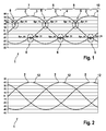
- the FIG. 1 shows a diagram 1, which represents three phase current waveforms 2, which were determined from Meßstromverierin not shown.
- the phase current profiles 2 are associated with a power network, not shown, which has three phases U, V and W, which each lead one of the currents I'_U, I'_V and I'_W.
- a first phase current curve 3 corresponds to the profile of the current I'-U
- a second phase current profile 4 to the profile of the current I'-V
- a third phase current curve 5 to the profile of the current I'_W.
- two measuring current curves were measured in the power network, which describe the characteristics of the currents I1_gem and I2_gem.
- the phase current profiles 2 have discontinuities 6, wherein configurations of the discontinuities 6 are equal between the phase current curves 2.
- four different jumps Spr_11, Spr_12, Spr_21 and Spr_22 are arranged.
- the jump Spr_11 leads on the example of the phase current waveform 3 to an increase for a period of time 7.
- the jump Spr_12 leads to a drop of the phase current curve 3 for a period 8, wherein the jump Spr_12 has the same jump height as the jump Spr_11.
- the jump Spr_21 leads to a renewed increase in the phase current profile 3, wherein the renewed increase is smaller than the rise of the jump Spr_21, the resulting rise for a period of time 9 applies.
- the jump heights are not limited to the heights and ratios shown.
- the jump Spr_22 which lowers the phase current curve 3 for the period 10, with the jumps Spr_21 and Spr_22 having the same jump height.
- the sequence of these jumps Spr_11, Spr_12, Spr_21 and Spr_22 occurs periodically and is the same for all phase current curves 2, whereby a corresponding time shift between the phase current curves 2 has to be considered.
- the FIG. 2 shows the diagram 1 with corrected phase current waveforms 2, which are sinusoidal waveforms 12.
- corrected phase current waveforms 2 To obtain the individual sections of the affected with discontinuities 6 phase current waveforms 2 from the FIG. 1 , as shown by the example of the phase current curve 3 in the time sections 7, 8, 9 and 10 along the jumps Spr_11, Spr_12, Spr_21 and Spr_22 shifted by a part of their associated jump heights.
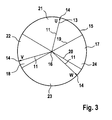
- the FIG. 3 shows a rotating phase vector 13, which represents the three phases U, V and W of the power grid.
- a phase vector 13 for example, serve a voltage vector, which is known about a further, additional measurement in the power grid or from a controller for the power network out.
- the phase vector 13 rotates counterclockwise.
- the rotating phase vector 13 has three phase vector branches 11, each phase vector branch 11 being associated with a phase U, V or W, furthermore the phase vector branches 11 are arranged at an angle of 120 ° to each other and all run with a peak 14 on a circular orbit 15 In addition, a horizontal straight line 17 passes through the center 16.
- the vertical distance of the peaks 14 from the straight line 17 corresponds to the instantaneous current value of the current I'_U, I'_V or I'_W associated with the phase U, V or W.
- the circle 18 enclosed by the circular orbit 15 is subdivided into four circle segments 21, 22, 23 and 24 by two straight lines 19 and 20, which run through the center point 16.
- the individual circle segments 21, 22, 23 and 24 determine how the phase current profile 2 is determined. If one of the phase vector branches 11 lies in the circular segment 21, then the phase current profile 2 assigned to the phase vector branch 11 is taken directly from the measuring current profile of the current I1_gem.
- phase current profile 2 from the measuring current profiles of the currents I1_gem and I2_gem is calculated for the corresponding phase U, V or W. If one of the phase vector branches 11 is in segment 23, the phase current profile 2 for the corresponding phase U, V or W is taken directly from the measurement current profile of the current I 2_gem. If one of the phase vector branches 11 lies in the circle segment 24, the phase current profile 2 is calculated for the corresponding phase U, V or W on the basis of the measuring current profiles I1_gem and I2_gem.
- FIG. 3 illustrated orbit 15 shows an error-free circular shape, resulting in the phase current waveforms 2 sinusoidal waveforms 12, as shown in FIG. 2 is shown. The location of the rotating phase vector 13 and thus the position of the phase vector branches 11 is determined by the rotation angle of the phase vector.
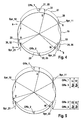
- FIG. 4 shows the representation of FIG. 3 , wherein additionally an orbit 26 is shown, which contains four discontinuities 6, which divides the orbit into four orbit segments 27, 28, 29 and 30.
- the orbit 26 represents the phase current waveforms 2 of FIG. 1
- the jump points 6 find their correspondences in the jumps Spr_11, Spr_12, Spr_21 and Spr_22.
- the orbit segments 27, 28, 29 and 30 each time a period 7, 8, 9 or 10 of the FIG. 1 assigned.
- the orbit segment 27 is assigned to the time segment 7, the orbit segment 28 to the time segment 8, the orbit segment 29 to the time segment 9 and the orbit segment 30 to the period 10.
- the orbit 26 shows different displacements 31, 32, 33 and 34 at various points in relation to the orbit 15, wherein the amounts of the displacements 31, 32 and 33 are different and the amounts of the displacements 32 and 34 are equal.
- the displacements 32 and 34 also represent an additional error 36.
- the displacements 31, 32, 33 and 34 each represent an inaccuracy 35, which prevails in their respective orbit segment 27, 28, 29 and 30. It thus results in an individual parallel displacement for each orbit segment 27, 28, 29 and 30 with respect to the orbit 15.
- real error values of the currents I1_gem and I2_gem were used.
- the current value of the displacement 31 is designated Offs_1
- the current value of the displacement 33 is designated Offs_2
- the current value of the displacements 32 and 34 is designated Offs_3.
- discontinuities 6 occur where a phase vector branch 11 changes from one segment 21, 22, 23 or 24 into another circle segment 21, 22, 23 or 24. Due to the arrangement of the circle segments 21, 22, 23 and 24 always arise simultaneously in two different phases U, V and / or W each have a discontinuity 6, wherein the types of discontinuities 6 between the phases U, V or W differ from each other. In particular, there is a relationship between simultaneously occurring discontinuities of different phases U, V or W, such that their jump heights are equal in terms of amount, but differ in sign.
- Offs_ 2 2 3 ⁇ Spr_ 21 - 1 3 ⁇ Spr_ 11
- Offs_ 1 2 3 ⁇ Spr_ 11 - 1 3 ⁇ Spr_ 21
- FIG. 6 shows the inventive method 37, wherein the method 37, the measured currents I1'_gem and I2'_gem via arrows 38 and 39 are supplied.
- Arrows 38 and 39 terminate in a correction unit 40 which calculates corrected currents I1 and I2 according to equations (8) and (9).
- the correction unit 40 is supplied with the current values Offs_1 and Offs_2 via arrows 41 and 42.
- the corrected currents I1 and I2 are forwarded via arrows 43 and 44 to a conversion unit 45, which converts the corrected currents I1 and I2 into the phase currents I'_U, I'_V and I'_W.
- the conversion is done by the in the FIGS. 3 to 5 explained method by means of a rotating phase vector 13.
- the three currents I'_U, I'_V and I'_W are provided via arrows 46, 47 and 48 for further analysis and processing.
- an arrow 49, 50 and 51 each goes off, which forward the currents I'_U, I'_V and I'_W to a jump determination 52.
- the jump determination 52 analyzes the phase current profiles 2, which are formed by the currents I'_U, I'_V and I'_W, and at the point in time of a jump 6 gives the current jumps Spr_11_a and Spr_21_a and their jump height via arrows 53 and 54 to a fault determination 55 - Also referred to as offset determination - continue.
- the error determination 55 calculates the current values Offs_1 and Offs_2, which are again transferred to the correction unit 40 via the arrows 41 and 42. Since the times of potential jump points 6 are known by the rotating phase vector 13, the corresponding current values of the jump heights of the jumps Spr_11_a or Spr_21_a can also be measured and evaluated at exactly this point in time. In all of this, it should be noted that always one of the three currents I'_U, I'_V or I'_W must be calculated using the node rule. Finally, this method leads to a continuous sinusoidal current waveform 12 for the currents I'_U, I'_V and I'_W of the phases U, V and W.
- the FIG. 7 shows a detailed view of the error detection 55 from FIG. 6 ,
- the error determination 55 has an error calculation 56, which forwards current values Offs_1_a and Offs_2_a to an error controller 59 by means of arrows 57 and 58.
- the current values Offs_1_a and Offs_2_a are supplied to a subtracter 60, to which a setpoint value 61 is fed via an arrow 62.
- the setpoint 61 is zero.
- the result of the subtractor 60 is forwarded by means of an arrow 63 to a gain element 64, which transmits the amplified signal via an arrow 65 to an adder 66.
- the result of the adder 66 is transmitted via an arrow 67 to a delay element 68, which is sent via an arrow 69 at the time of a jump 6, a trigger signal, whereby the delay element is switched further.
- the result of the delay element 68 corresponds in each case to the current values Offs_1 and Offs_2. Via an arrow 70, these values are fed back to summer 66.
- the error calculation 56 calculates the current values Offs_1_a and Offs_2_a using equations (6) and (7), in which case Offs_1 is replaced by Offs_1_a and Offs_2 by Offs_2_a in the equations. These values are first applied to a desired value 61 in the subtractor 60 and then amplified in the amplifier 64.
- the amplifier 64 thus serves as a P element 71 of the error controller 59.
- the delay element 68 together with the summer 66, an I element 72 of the error controller 59, which integrates at each discontinuity 6, if the I element via the arrow 69, the trigger signal is transmitted.
- the jumps Spr_11, Spur_12, Spr_21 and Spr_22 occur for the currents I'_U, I'_V and I'_W of the phase-current profiles 2, respectively. As in FIG. 1 set out, they each form pairs of equal jump heights. Therefore, only the jumps Spr_11 and Spr_21 were selected for the considerations presented here.
Landscapes
- Engineering & Computer Science (AREA)
- Power Engineering (AREA)
- Physics & Mathematics (AREA)
- General Physics & Mathematics (AREA)
- Control Of Ac Motors In General (AREA)
- Testing Electric Properties And Detecting Electric Faults (AREA)
Abstract
Description
Die Erfindung betrifft ein Verfahren zur Strommessung von Phasenströmen mittels einer Messschaltung in einem mehrphasigen Stromnetz, in dem durch mindestens ein steuerbares Schaltelement eine gewünschte Bestromung mindestens eines elektrischen Verbrauchers erfolgt und auf das Schaltelement Steuersignale wirken, um die gewünschte Bestromung des Verbrauchers zu erreichen, wobei Taktmustern der Ansteuersignale Messfenster für die Strommessung zugeordnet sind und Taktmuster für eine gewünschte Messfenstergröße und/oder -position zeitlich verschoben werden, wobei bei der Strommessung mindestens ein Stromwerte aufweisender Messstromverlauf gemessen wird, der aufgrund der verschobenen Taktmuster mindestens einen Fehler aufweist, wobei aus dem Messstromverlauf ein Stromwerte aufweisender Phasenstromverlauf ermittelt wird, bei dem der Fehler mindestens eine Sprungstelle bewirkt.The invention relates to a method for current measurement of phase currents by means of a measuring circuit in a multi-phase power network, in which at least one controllable switching element, a desired energization of at least one electrical load and acting on the switching element control signals to achieve the desired energization of the consumer, wherein clock patterns The control signals are associated with measuring windows for the current measurement and clock patterns for a desired measuring window size and / or position are shifted in time, wherein in the current measurement at least one Stromwerte exhibiting measuring current waveform is measured, which has at least one error due to the shifted clock pattern, wherein from the measuring current course Current values exhibiting phase current profile is determined, at which the error causes at least one jump.
Bei Elektromotoren mit mehrphasiger Ansteuerung besteht oft der Wunsch, die Phasenströme zu erfassen. Handelt es sich um eine Bestromung eines Elektromotors mittels einer steuerbaren Brücke, die in ihren einzelnen Brückenzweigen steuerbare Schaltelemente aufweist, so lässt sich der Elektromotor in gewünschter Weise bestromen. Zu diesem Zweck werden die Schaltelemente mit Taktmustern angesteuert, die beispielsweise auf Basis einer mittenzentrierten Pulsweitenmodulation erzeugt werden. Um die Phasenströme zu erfassen, wird in jeder Phasenleitung ein niederohmiger Widerstand (Shunt) angeordnet. Der Aufwand dieser mehrphasigen Messanordnung ist entsprechend groß. Um den Aufwand zu verkleinern, kann ein einzelner Shunt in eine gemeinsame Leitung gelegt werden, mit der jede Phasenleitung verbunden ist. Werden dann die Ansteuersignale der Schaltelemente derart zueinander verschoben, sodass die Schaltelemente sequenziell geschaltet werden, bilden sich zwischen den einzelnen Schaltungen der Schaltelemente Messfenster, innerhalb derer Messungen durchgeführt werden können. Die nacheinander durchgeführten Messungen ergeben Stromwerte unterschiedlicher Messstromverläufe. Diese ermöglichen einen Rückschluss auf die Phasenströme der einzelnen Phasen, wobei die einzelnen Messstromverläufe analysiert werden müssen, um die Phasenstromverläufe ermitteln zu können. Durch das Verschieben der Ansteuersignale bilden sich Blindstromanteile im Stromnetz, die bei Erfassung des Messstromverlaufs am Shunt einen Fehler bewirken. Bei der Analyse des Messstromverlaufs ergeben sich aufgrund des Fehlers in dem ermittelten Phasenstromverlauf Sprungstellen, wodurch der Phasenstromverlauf bereichsweise, nämlich von einem Sprung zu einem nächsten Sprung seinerseits eine Ungenauigkeit aufweist.In multiphase drive motors, there is often a desire to detect the phase currents. If it is an energization of an electric motor by means of a controllable bridge, which has controllable switching elements in their individual bridge branches, then the electric motor can be energized in the desired manner. For this purpose, the switching elements are driven by clock patterns, which are generated for example on the basis of a center-centered pulse width modulation. In order to detect the phase currents, a low-resistance resistor (shunt) is arranged in each phase line. The cost of this multiphase measuring arrangement is correspondingly large. To reduce the effort, a single shunt can be placed in a common line to which each phase line is connected. Will then the control signals of the switching elements to each other shifted, so that the switching elements are switched sequentially, between the individual circuits of the switching elements measuring windows are formed, within which measurements can be performed. The successive measurements yield current values of different measuring current curves. These allow conclusions to be drawn about the phase currents of the individual phases, whereby the individual measuring current profiles must be analyzed in order to be able to determine the phase current characteristics. By shifting the control signals, reactive current components are formed in the power network, which cause a fault on detection of the measurement current profile at the shunt. In the analysis of the measurement current profile, due to the error in the determined phase current profile, discontinuities occur, whereby the phase current profile in some areas, namely from one jump to a next jump, in turn has an inaccuracy.
Die Ungenauigkeit wird im Stand der Technik bei Fertigungsende einer entsprechenden Baugruppe durch einmalige Kalibrierung beseitigt, dem Bandende-Abgleich. Eine weitere Berücksichtigung während einer Bauteillebensdauer erfolgt nicht, weshalb ein erneutes Auftreten der Ungenauigkeit nicht erkannt und korrigiert werden kann.The inaccuracy is eliminated in the prior art at the end of production of a corresponding assembly by a single calibration, the end-of-band adjustment. Further consideration during a component life does not take place, which is why a recurrence of the inaccuracy can not be detected and corrected.
Der Erfindung liegt die Aufgabe zugrunde, eine sehr einfache und kostengünstige Strommessung zu ermöglichen, wobei der Fehler stets korrekt korrigiert wird.The invention has for its object to enable a very simple and inexpensive power measurement, the error is always corrected correctly.
Bei dem erfindungsgemäßen Verfahren ist vorgesehen, dass das Auftreten der Sprungstelle erfasst wird, dass die Sprunghöhe der Sprungstelle ermittelt wird und dass der Phasenstromverlauf in Abhängigkeit der Sprunghöhe derart korrigiert wird, dass der der Sprunghöhe entsprechende Stromwert im sich an die Sprungstelle anschließenden zeitlichen Verlauf von den Stromwerten des Messstromverlaufs zumindest teilweise abgezogen oder zu diesem zumindest teilweise addiert wird. Der Fehler bildet sich aufgrund von Blindstromanteilen durch die Taktverschiebung der Ansteuersignale, insbesondere dann, wenn die Ströme über einen elektrischen Knoten miteinander in Wechselwirkung stehen.In the method according to the invention, it is provided that the occurrence of the discontinuity is detected, that the jump height of the discontinuity is determined, and that the phase current profile is corrected in dependence on the step height such that the current value corresponding to the step height in the time course following the discontinuity of the step Current values of the measuring current profile at least partially subtracted or added to this at least partially. The error is due to reactive current components due to the clock shift of the drive signals, especially when the currents are interacting with each other via an electrical node.
Dieses Ungleichgewicht an dem Knoten führt zu Blindströmen, die die Strommessung und damit den Messstromverlauf mit dem Fehler behaften. Das Verfahren ermöglicht eine automatische und adaptive Korrektur der durch die Sprungstellen erzeugten Ungenauigkeiten in dem Phasenstromverlauf, da jede Sprungstelle analysiert wird, und ihr Einfluss auf das Messergebnis korrigiert wird. Somit werden auch Temperatur- und Alterungseffekte, sowie unterschiedliche Einflüsse in verschiedenen Arbeitspunkten des elektrischen Verbrauchers stets berücksichtigt und ermöglichen somit eine hochgenaue Strommessung.This imbalance at the node leads to reactive currents, which affect the current measurement and thus the measuring current course with the error. The method enables automatic and adaptive correction of the inaccuracies in the phase current profile generated by the discontinuities, since each discontinuity is analyzed and its influence on the measurement result is corrected. Thus, temperature and aging effects, as well as different influences in different operating points of the electrical load are always considered and thus enable a highly accurate current measurement.
Nach einer bevorzugten Weiterbildung der Erfindung ist vorgesehen, dass das Stromnetz einen rotierenden Phasenvektor aufweist und dass aus dem Messstromverlauf ein Phasenstromverlauf ermittelt wird, indem die Stromwerte des Phasenstromverlaufs in Abhängigkeit eines Drehwinkels des Phasenvektors dem Messstromverlauf direkt entnommen werden und/oder aus Stromwerten mindestens eines Messstromverlaufs berechnet werden. Bei einer sequenziellen Strommessung enthält der Messstromverlauf entweder einen einzelnen Phasenstromverlauf oder eine Kombination mehrerer Phasenstromverläufe, ferner kann vorgesehen sein, dass mindestens ein Teil des Phasenstromverlaufs berechnet wird. Das Verfahren wird bevorzugt dann angewendet, wenn das Stromnetz mittels Pulsweitenmodulation durch die Schaltelemente betrieben wird. Dabei werden die Taktmuster in Abhängigkeit der Phasenlage des Phasenstromverlaufs verschoben, weshalb sich aus dem Drehwinkel, der die Phasenlage des Phasenstromverlaufs wiedergibt, der momentane Inhalt des Messstromverlaufs ableiten lässt. So ergibt sich aus einem bestimmten Drehwinkel, insbesondere einem Drehwinkelbereich, welchen Inhalt der Messstromverlauf aktuell führt. Anhand dieser Informationen kann der gewünschte Phasenstromverlauf entweder dem Messstromverlauf entnommen werden oder anhand elektrischer Gleichungen berechnet werden.According to a preferred development of the invention, it is provided that the power network has a rotating phase vector and that a phase current profile is determined from the measurement current profile by directly taking the current values of the phase current profile as a function of a rotation angle of the phase vector from the measurement current profile and / or from current values of at least one measurement current profile be calculated. In the case of a sequential current measurement, the measurement current course contains either a single phase current profile or a combination of a plurality of phase current characteristics, and it can also be provided that at least part of the phase current profile is calculated. The method is preferably used when the power grid is operated by means of pulse width modulation by the switching elements. In this case, the clock patterns are shifted as a function of the phase position of the phase current profile, which is why the instantaneous content of the measuring current profile can be derived from the angle of rotation which reproduces the phase position of the phase current profile. Thus results from a certain angle of rotation, in particular a rotation angle range, which content of the measuring current currently leads. Based on this information, the desired phase current profile can either be taken from the measurement current profile or calculated using electrical equations.
Nach einer Weiterbildung der Erfindung ist vorgesehen, dass das Auftreten der Sprungstelle erfasst wird, wenn innerhalb einer festgelegten Zeitspanne ein Anstieg und/oder ein Abfall der Stromwerte des Phasenstromverlaufs eines vorgegebenen Schwellwerts über- oder unterschreitet. Insbesondere bei bekanntem Phasenstromverlauf ist es vorteilhaft, wenn als Schwellwert ein maximaler Anstieg oder ein maximaler Abfall innerhalb einer bestimmten Zeitspanne angegeben wird. Wird dieser Schwellwert von dem Phasenstromverlauf nicht eingehalten, so kann von einer Sprungstelle ausgegangen werden.According to a development of the invention, it is provided that the occurrence of the discontinuity is detected when, within a defined period of time, an increase and / or a fall in the current values of the phase current profile exceeds or falls below a predetermined threshold value. In particular, with known phase current profile, it is advantageous if a threshold value maximum increase or maximum waste within a certain period of time. If this threshold value is not met by the phase current profile, then it can be assumed that there is a discontinuity.
Nach einer Weiterbildung des Verfahrens ist vorgesehen, dass das Auftreten der Sprungstelle erfasst wird, wenn eine Abweichung des Phasenstromverlaufs von einem berechneten und/oder abgeschätzt erwarteten Phasenstromverlauf auftritt und die Abweichung einen Schwellwert über- oder unterschreitet. Bei digitalen Messungen kann die Erfassung eines Sprunges mittels eines maximalen Anstiegs oder Abfalls von einem Messpunkt zum nächsten zu Fehlerfassungen führen, da der Verlauf zwischen den Messpunkten nicht erfasst wird. Dies ist insbesondere dann der Fall, wenn der Phasenvektor hohe Winkelgeschwindigkeiten aufweist und/oder hohe Stromamplituden betrachtet werden. Es ist daher sinnvoll, eine Abschätzung des nächsten zu erwartenden Stromwerts im Phasenstromverlauf vorzunehmen, um eine mögliche Abweichung des erfassten Stromwerts des Phasenstromverlaufs von dem erwarteten Stromwert auswerten zu können. Diese Auswertung kann wiederum über einen Schwellwert erfolgen.According to a development of the method, it is provided that the occurrence of the discontinuity is detected when a deviation of the phase current profile from a calculated and / or estimated expected phase current profile occurs and the deviation exceeds or falls below a threshold value. In digital measurements, the detection of a jump by means of a maximum increase or decrease from one measurement point to the next can lead to error detections, since the course between the measurement points is not detected. This is the case in particular when the phase vector has high angular velocities and / or high current amplitudes are considered. It therefore makes sense to make an estimate of the next expected current value in the phase current profile in order to be able to evaluate a possible deviation of the detected current value of the phase current profile from the expected current value. This evaluation can again take place via a threshold value.
Nach einer Weiterbildung der Erfindung ist vorgesehen, dass bei mindestens einem bestimmten Drehwinkel des Phasenvektors immer eine Sprungstelle auftritt und dass das Auftreten dieser Sprungstelle anhand des Drehwinkels erfasst wird. Wie bereits erwähnt, kann bei einem Stromnetz mit einem rotierenden Phasenvektor der Drehwinkel des Phasenvektors in Bereiche eingeteilt werden, in welchen der Phasenstromverlauf auf unterschiedliche Weise aus dem Messstromverlauf ermittelt wird. Eine Sprungstelle tritt insbesondere dann auf, wenn ein Übergang von einem solchen Drehwinkelbereich in einen anderen Drehwinkelbereich vollzogen wird, da dann von einer Weise des Ermittelns in eine nächste, andere Weise des Ermittelns gewechselt wird. Durch diesen Wechsel wird der Fehler in dem Messstromverlauf unterschiedlich berücksichtigt, wodurch Sprungstellen entstehen. Somit lassen sich derartig gebildete Sprungstellen anhand des Drehwinkels, insbesondere anhand des Übergangs des Drehwinkels von einem Drehwinkelbereich in einen nächsten Drehwinkelbereich einfach und schnell erfassen.According to a development of the invention, it is provided that at least one specific angle of rotation of the phase vector always a jump occurs and that the occurrence of this discontinuity is detected on the basis of the rotation angle. As already mentioned, in the case of a power network having a rotating phase vector, the angle of rotation of the phase vector can be divided into regions in which the phase current profile is determined in different ways from the measuring current profile. In particular, a discontinuity occurs when a transition is made from such a rotation angle range to another rotation angle range, because then a way of determining changes in a next, different way of determining. Due to this change, the error in the measuring current profile is taken into account differently, which causes discontinuities. Thus, discontinuities formed in this way can be based on the angle of rotation, in particular on the basis of the transition of the angle of rotation of a Detect turning angle range in a next rotation angle range easily and quickly.
Nach einer Weiterbildung der Erfindung ist vorgesehen, dass der Messstromverlauf aufgrund von mindestens einem Bauteilestreuungs-, Temperatur- und/oder Alterungseffekt der Messschaltung mindestens einen über den Messstromverlauf weitgehend gleichförmigen Zusatzfehler aufweist, der im Phasenstromverlauf eine Veränderung der Sprunghöhe der Sprungstelle bewirkt, wobei mittels elektrischer Gleichungen des elektrischen Verbrauchers, insbesondere elektrische Maschinengleichung einer den elektrischen Verbraucher darstellenden elektrischen Maschine, und der Sprunghöhe der Stromwert der Veränderung berechnet wird, welcher von dem Messstromverlauf abgezogen oder zu diesem addiert wird. Derartige Effekte der Messschaltungen führen dazu, dass die Stromwerte des Messstromverlaufs alle weitgehend auf die gleiche Weise vergrößert oder verkleinert werden, also dass der Messstromverlauf im Gesamten verschoben wird. Da diese Verschiebung sich auf die einzelnen Sprunghöhen auswirkt, kann anhand der Sprunghöhe durch geeignete elektrische Gleichungen, wie elektrischen Gleichungen des elektrischen Verbrauchers, die Veränderung berechnet werden, welche ausschließlich aus einem oder mehreren der Effekte der Messschaltung entsteht. Auf diese Weise ist eine Kompensation derartiger Effekte möglich, was insgesamt eine hohe Adaptivität und Genauigkeit der Strommessung ermöglicht. Unter Bauteilestreuungseffekten werden Effekte verstanden, die in einzelnen Bauteilen der Schaltung, insbesondere der Messschaltung, aufgrund produktionsbedingter Abweichungen entstehen, beispielsweise durch Fertigungstoleranzen, aus denen eine Messabweichung und/oder ein Messrauschen hervorgeht.According to a development of the invention, it is provided that the measuring current profile due to at least one component scattering, temperature and / or aging effect of the measuring circuit has at least one over the measuring current course substantially uniform additional error, which causes a change in the jump height of the jump point in the phase current profile, wherein by means of electrical Equations of the electrical load, in particular electrical machine equation of an electrical consumer representing electric machine, and the jump height of the current value of the change is calculated, which is subtracted from the Meßstromverlauf or added to this. Such effects of the measuring circuits lead to the fact that the current values of the measuring current profile are all largely increased or reduced in the same way, ie that the measuring current profile is shifted in its entirety. Since this shift affects the individual jump heights, the change can be calculated from the jump height by means of suitable electrical equations, such as electrical equations of the electrical load, which change arises exclusively from one or more of the effects of the measurement circuit. In this way, a compensation of such effects is possible, which allows a high overall adaptability and accuracy of the current measurement. Sub-component scattering effects are understood to mean effects that arise in individual components of the circuit, in particular the measuring circuit, due to production-related deviations, for example due to manufacturing tolerances, from which a measurement error and / or measurement noise is evident.
Nach einer Weiterbildung des Verfahrens ist vorgesehen, dass der der Sprunghöhe entsprechende Stromwert und/oder der der Veränderung der Sprunghöhe entsprechende Stromwert des Phasenstromverlaufs von dem Messstromverlauf in einem bis zu einer weiteren, nachfolgenden Sprungstelle reichenden Zeitabschnitt unverändert abgezogen oder zum Messstromverlauf unverändert addiert wird/werden. Wird eine Sprungstelle erfasst und deren Sprunghöhe ermittelt, so wird der Phasenstromverlauf in Abhängigkeit dieser aktuellen Sprunghöhe korrigiert. Das Korrigieren wird solange anhand desselben Wertes, der sich in Abhängigkeit der aktuellen Sprunghöhe ergibt, vorgenommen, bis eine erneute Sprungstelle erfasst wird, wonach sich das Verfahren periodisch wiederholt. Eine Möglichkeit, den Phasenstromverlauf kontinuierlich auf diese Weise zu korrigieren, ergibt sich mittels einer Regelung, insbesondere einer Regelung mit einem proportionalen und einem integralen Anteil.According to a development of the method, it is provided that the current value corresponding to the jump height and / or the current value of the phase current profile corresponding to the change in the jump height are subtracted unchanged from the measurement current profile in a time interval extending to a further, subsequent discontinuity or added unchanged to the measurement current profile , If a jump is detected and its jump height determined, the phase current curve becomes dependent on this corrected for the current jump height. The correction is made on the basis of the same value, which results in dependence on the current jump height, until a new jump position is detected, after which the method repeats periodically. One way of continuously correcting the phase current profile in this way is by means of a control, in particular a control with a proportional and an integral component.
Es ist ferner denkbar, das Verfahren bei Systemen anzuwenden, welche einen nicht oder nur zeitweise rotierenden Phasenvektor aufweisen, in dem eine Umschaltung zwischen unterschiedlichen Weisen der Ermittlung des Phasenstromverlaufs, beispielsweise anhand erwarteter Stromwerte oder eines durch eine Steuerung vorgesehenen oder angenommenen Stromzustandes, ermittelt werden und somit auch für derartige Systeme eine adaptive Korrektur von Sprungstellen und insbesondere adaptive Korrektur von Temperatur- und/oder Alterungseffekten der Messschaltung zu ermöglichen.It is furthermore conceivable to use the method in systems which have a phase vector which does not rotate or only intermittently, in which a changeover between different ways of determining the phase current profile, for example based on expected current values or a current state provided or assumed by a controller, is determined and Thus, for such systems to allow an adaptive correction of discontinuities and in particular adaptive correction of temperature and / or aging effects of the measuring circuit.
Die Zeichnungen veranschaulichen die Erfindung anhand eines Ausführungsbeispiels, und zwar zeigt:
Figur 1- ein Diagramm mit Phasenstromverläufen die Sprungstellen aufweisen,
Figur 2- ein Diagramm mit korrigierten Phasenstromverläufen,
Figur 3- einen rotierenden Phasenvektor,
Figur 4- einen rotierenden Phasenvektor der Sprungstellen aufweist,
Figur 5- einen rotierenden Phasenvektor mit einer Zusammensetzung der Sprungstellen,
Figur 6- eine schematische Darstellung des erfindungsgemäßen Verfahrens,
- Figur 7
- eine Ermittlung der von dem Messstromverlauf abzuziehenden Stromwerte mit einer Regelung.
- FIG. 1
- a diagram with phase current curves that have jump points,
- FIG. 2
- a diagram with corrected phase current curves,
- FIG. 3
- a rotating phase vector,
- FIG. 4
- has a rotating phase vector of the discontinuities,
- FIG. 5
- a rotating phase vector with a composition of the discontinuities,
- FIG. 6
- a schematic representation of the method according to the invention,
- FIG. 7
- a determination of the current values to be subtracted from the measurement current profile with a control.
Die
Die
Die
Die 
Daraus ergibt sich, dass die Sprungstellen 6 dort auftreten, wo ein Phasenvektorast 11 von einem Segment 21, 22, 23 oder 24 in ein anderes Kreissegment 21, 22, 23 oder 24 wechselt. Aufgrund der Anordnung der Kreissegmente 21, 22, 23 und 24 entstehen immer gleichzeitig in zwei verschiedenen Phasen U, V und/oder W jeweils eine Sprungstelle 6, wobei sich die Arten der Sprungstellen 6 zwischen den Phasen U, V oder W voneinander unterscheiden. Insbesondere ergibt sich ein Zusammenhang zwischen gleichzeitig auftretenden Sprungstellen verschiedener Phasen U, V oder W, derart, dass deren Sprunghöhen betragsweise gleich sind, sich jedoch im Vorzeichen unterscheiden.It follows that the
Die 

Aus Gleichung (1), Gleichung (2) und Gleichung (3) ergibt sich ![]()
und ![]()
![]()
and ![]()
Dies führt zu zwei Gleichungen mit zwei Unbekannten, aus denen sich die Stromwerte Offs_1 und Offs_2 der Verschiebungen 31 und 33 aus den beiden Sprüngen Spr_11 und Spr_21 wie folgt ergeben: 

Die in den Messstromverläufen gemessenen Ströme I1_gem und I2_gem können mittels der Stromwerte Offs_1 und Offs_2 der Fehler 35 zu Strömen I1 und I2 wie folgt korrigiert werden: ![]()

![]()
Die
Die
Mit dieser Methode ist es möglich, Fehler und Sprungstellen bei einer Strommessung, insbesondere mit rotierendem Phasenvektor 13 adaptiv nachzuregeln. Damit können entsprechende Abgleichschritte bei einer Produktion entfallen. Außerdem kann die Qualität der Strommessung über Lebensdauer und Temperatur entsprechender Bauteile verbessert werden, die das Verfahren verwenden. Einschränkungen des zulässigen Toleranzbereiches für einen Bandende-Abgleich um Lebenszeitdriften zu berücksichtigen, wären ferner nicht mehr notwendig. Dadurch kann unter Umständen eine Ausschlussrate in Produktionen reduziert werden.With this method, it is possible to adaptively correct errors and discontinuities in a current measurement, in particular with a
Claims (7)
Applications Claiming Priority (1)
| Application Number | Priority Date | Filing Date | Title |
|---|---|---|---|
| DE102008001586A DE102008001586A1 (en) | 2008-05-06 | 2008-05-06 | Method for error correction in a current measurement in a multi-phase power network |
Publications (3)
| Publication Number | Publication Date |
|---|---|
| EP2116856A2 true EP2116856A2 (en) | 2009-11-11 |
| EP2116856A3 EP2116856A3 (en) | 2014-05-07 |
| EP2116856B1 EP2116856B1 (en) | 2018-08-15 |
Family
ID=41087365
Family Applications (1)
| Application Number | Title | Priority Date | Filing Date |
|---|---|---|---|
| EP09100170.1A Not-in-force EP2116856B1 (en) | 2008-05-06 | 2009-03-10 | Method for correcting errors in an electricity measurement in a multi-phase electricity network |
Country Status (2)
| Country | Link |
|---|---|
| EP (1) | EP2116856B1 (en) |
| DE (1) | DE102008001586A1 (en) |
Cited By (1)
| Publication number | Priority date | Publication date | Assignee | Title |
|---|---|---|---|---|
| CN113272666A (en) * | 2018-12-27 | 2021-08-17 | 罗伯特·博世有限公司 | Method for obtaining an enhanced error of a current measuring device |
Families Citing this family (1)
| Publication number | Priority date | Publication date | Assignee | Title |
|---|---|---|---|---|
| US11217465B2 (en) | 2017-04-11 | 2022-01-04 | Muehlbauer GmbH & Co. KG | Component receiving device with optical sensor |
Citations (5)
| Publication number | Priority date | Publication date | Assignee | Title |
|---|---|---|---|---|
| DE4013089A1 (en) * | 1990-04-25 | 1991-10-31 | Bosch Gmbh Robert | IC engine control input voltage error corrected measurement - deriving accurate value of auxiliary parameter and replacement of reference parameter with derived digital ratio |
| US5436819A (en) * | 1991-07-25 | 1995-07-25 | Mitsubishi Denki Kabushiki Kaisha | Apparatus for and method of compensating for an output voltage error in an inverter output |
| JP2004135441A (en) * | 2002-10-11 | 2004-04-30 | Daikin Ind Ltd | Motor driving method and its device |
| US20040169488A1 (en) * | 2001-09-29 | 2004-09-02 | Toshiyuki Maeda | Phase current detection method, inverter control method, motor control method, and apparatuses used in these methods |
| US20070090785A1 (en) * | 2005-10-26 | 2007-04-26 | Ho Eddy Y Y | Audible noise reduction for single current shunt platform |
-
2008
- 2008-05-06 DE DE102008001586A patent/DE102008001586A1/en not_active Withdrawn
-
2009
- 2009-03-10 EP EP09100170.1A patent/EP2116856B1/en not_active Not-in-force
Patent Citations (5)
| Publication number | Priority date | Publication date | Assignee | Title |
|---|---|---|---|---|
| DE4013089A1 (en) * | 1990-04-25 | 1991-10-31 | Bosch Gmbh Robert | IC engine control input voltage error corrected measurement - deriving accurate value of auxiliary parameter and replacement of reference parameter with derived digital ratio |
| US5436819A (en) * | 1991-07-25 | 1995-07-25 | Mitsubishi Denki Kabushiki Kaisha | Apparatus for and method of compensating for an output voltage error in an inverter output |
| US20040169488A1 (en) * | 2001-09-29 | 2004-09-02 | Toshiyuki Maeda | Phase current detection method, inverter control method, motor control method, and apparatuses used in these methods |
| JP2004135441A (en) * | 2002-10-11 | 2004-04-30 | Daikin Ind Ltd | Motor driving method and its device |
| US20070090785A1 (en) * | 2005-10-26 | 2007-04-26 | Ho Eddy Y Y | Audible noise reduction for single current shunt platform |
Non-Patent Citations (1)
| Title |
|---|
| BLAABJERG F ET AL: "An ideal PWM-VSI inverter using only one current sensor in the DC-link", 19940101, 1. Januar 1994 (1994-01-01), Seiten 458-464, XP006511326, * |
Cited By (2)
| Publication number | Priority date | Publication date | Assignee | Title |
|---|---|---|---|---|
| CN113272666A (en) * | 2018-12-27 | 2021-08-17 | 罗伯特·博世有限公司 | Method for obtaining an enhanced error of a current measuring device |
| CN113272666B (en) * | 2018-12-27 | 2024-05-14 | 罗伯特·博世有限公司 | Method for detecting an enhancement error of a current measuring device |
Also Published As
| Publication number | Publication date |
|---|---|
| EP2116856B1 (en) | 2018-08-15 |
| DE102008001586A1 (en) | 2009-11-12 |
| EP2116856A3 (en) | 2014-05-07 |
Similar Documents
| Publication | Publication Date | Title |
|---|---|---|
| EP3531141A1 (en) | Method and device for network condition monitoring | |
| DE102007054434B3 (en) | Sensor system analyzing method for e.g. automatic gearbox, in motor vehicle, involves determining position of selector fork depending on base output signal, function for amplification factor and base response curve | |
| EP2696175A1 (en) | Method for detecting the flow rate of a centrifugal pump | |
| EP2360483B1 (en) | Method and device for current measurement in a multi-phase electrical network | |
| WO2015132064A2 (en) | Method for determining phase currents in an electrical multi-phase system | |
| EP2265964B1 (en) | Method and device for current measurement in phase lines | |
| EP3164724B1 (en) | Method and device for testing a tap changer of a transformer | |
| EP3164726B1 (en) | Method and device for testing a tap changer of a transformer | |
| EP0204897B1 (en) | Method and device for controlling the mark-to-space ratio of an electric signal | |
| EP1853927B1 (en) | Motion sensor equipped with encoder monitoring circuit and corresponding encoder monitoring method | |
| EP2116856B1 (en) | Method for correcting errors in an electricity measurement in a multi-phase electricity network | |
| EP1340988B1 (en) | Method and device for measuring the impedance in an electrical energy supply network | |
| WO2019122311A1 (en) | Monitoring method for a wind turbine, associated monitoring device, and wind turbine having a monitoring device | |
| DE102013213566B4 (en) | Device and method for measuring a current | |
| EP3058381B1 (en) | Method for determining the supply voltages of a consumer and consumer | |
| EP2593800B1 (en) | Method or voltage detection system for determining a correction parameter for a measurement channel and for detecting a terminal voltage of an electric motor | |
| DE102015205772B3 (en) | Method for generating a speed signal of an electric motor | |
| EP3164725B1 (en) | Method and device for testing a tap changer of a transformer | |
| EP3014756B1 (en) | Method for detecting an incorrect angular position of an electric motor | |
| DE4233110A1 (en) | Measuring electrical conductivity of liquids, esp. electrolytes - comparing conductivity values obtained for two different ac current frequencies to detect measurement errors | |
| EP3076193A1 (en) | Device and method for measuring a current in a conductor in an on-board electrical network of a motor vehicle | |
| EP1988402A2 (en) | Method for determining work/power | |
| EP3197748B1 (en) | Method for identifying an error state in a brushless direct current motor | |
| EP1879289B1 (en) | Determination of the angle of rotation of an electric motor | |
| EP2777144A2 (en) | Method for calibrating a multiphase inverter, operating apparatus, computer program, and computer program product |
Legal Events
| Date | Code | Title | Description |
|---|---|---|---|
| PUAI | Public reference made under article 153(3) epc to a published international application that has entered the european phase |
Free format text: ORIGINAL CODE: 0009012 |
|
| AK | Designated contracting states |
Kind code of ref document: A2 Designated state(s): AT BE BG CH CY CZ DE DK EE ES FI FR GB GR HR HU IE IS IT LI LT LU LV MC MK MT NL NO PL PT RO SE SI SK TR |
|
| AX | Request for extension of the european patent |
Extension state: AL BA RS |
|
| PUAL | Search report despatched |
Free format text: ORIGINAL CODE: 0009013 |
|
| AK | Designated contracting states |
Kind code of ref document: A3 Designated state(s): AT BE BG CH CY CZ DE DK EE ES FI FR GB GR HR HU IE IS IT LI LT LU LV MC MK MT NL NO PL PT RO SE SI SK TR |
|
| AX | Request for extension of the european patent |
Extension state: AL BA RS |
|
| RIC1 | Information provided on ipc code assigned before grant |
Ipc: G01R 19/00 20060101AFI20140331BHEP Ipc: G01R 25/00 20060101ALN20140331BHEP |
|
| 17P | Request for examination filed |
Effective date: 20141107 |
|
| RBV | Designated contracting states (corrected) |
Designated state(s): AT BE BG CH CY CZ DE DK EE ES FI FR GB GR HR HU IE IS IT LI LT LU LV MC MK MT NL NO PL PT RO SE SI SK TR |
|
| AKX | Designation fees paid |
Designated state(s): AT BE BG CH CY CZ DE DK EE ES FI FR GB GR HR HU IE IS IT LI LT LU LV MC MK MT NL NO PL PT RO SE SI SK TR |
|
| AXX | Extension fees paid |
Extension state: RS Extension state: BA Extension state: AL |
|
| GRAP | Despatch of communication of intention to grant a patent |
Free format text: ORIGINAL CODE: EPIDOSNIGR1 |
|
| STAA | Information on the status of an ep patent application or granted ep patent |
Free format text: STATUS: GRANT OF PATENT IS INTENDED |
|
| RIC1 | Information provided on ipc code assigned before grant |
Ipc: H02M 1/00 20060101ALI20180503BHEP Ipc: G01R 25/00 20060101ALN20180503BHEP Ipc: G01R 19/00 20060101AFI20180503BHEP Ipc: H02M 7/5387 20070101ALI20180503BHEP |
|
| INTG | Intention to grant announced |
Effective date: 20180518 |
|
| RIC1 | Information provided on ipc code assigned before grant |
Ipc: H02M 1/00 20060101ALI20180507BHEP Ipc: G01R 19/00 20060101AFI20180507BHEP Ipc: G01R 25/00 20060101ALN20180507BHEP Ipc: H02M 7/5387 20070101ALI20180507BHEP |
|
| RIN1 | Information on inventor provided before grant (corrected) |
Inventor name: FINKE, SVEN Inventor name: KUEHN, TIMO |
|
| GRAS | Grant fee paid |
Free format text: ORIGINAL CODE: EPIDOSNIGR3 |
|
| GRAA | (expected) grant |
Free format text: ORIGINAL CODE: 0009210 |
|
| STAA | Information on the status of an ep patent application or granted ep patent |
Free format text: STATUS: THE PATENT HAS BEEN GRANTED |
|
| AK | Designated contracting states |
Kind code of ref document: B1 Designated state(s): AT BE BG CH CY CZ DE DK EE ES FI FR GB GR HR HU IE IS IT LI LT LU LV MC MK MT NL NO PL PT RO SE SI SK TR |
|
| REG | Reference to a national code |
Ref country code: CH Ref legal event code: EP Ref country code: GB Ref legal event code: FG4D Free format text: NOT ENGLISH Ref country code: AT Ref legal event code: REF Ref document number: 1030390 Country of ref document: AT Kind code of ref document: T Effective date: 20180815 |
|
| REG | Reference to a national code |
Ref country code: IE Ref legal event code: FG4D Free format text: LANGUAGE OF EP DOCUMENT: GERMAN |
|
| REG | Reference to a national code |
Ref country code: DE Ref legal event code: R096 Ref document number: 502009015188 Country of ref document: DE |
|
| REG | Reference to a national code |
Ref country code: NL Ref legal event code: MP Effective date: 20180815 |
|
| REG | Reference to a national code |
Ref country code: LT Ref legal event code: MG4D |
|
| PG25 | Lapsed in a contracting state [announced via postgrant information from national office to epo] |
Ref country code: GR Free format text: LAPSE BECAUSE OF FAILURE TO SUBMIT A TRANSLATION OF THE DESCRIPTION OR TO PAY THE FEE WITHIN THE PRESCRIBED TIME-LIMIT Effective date: 20181116 Ref country code: IS Free format text: LAPSE BECAUSE OF FAILURE TO SUBMIT A TRANSLATION OF THE DESCRIPTION OR TO PAY THE FEE WITHIN THE PRESCRIBED TIME-LIMIT Effective date: 20181215 Ref country code: NO Free format text: LAPSE BECAUSE OF FAILURE TO SUBMIT A TRANSLATION OF THE DESCRIPTION OR TO PAY THE FEE WITHIN THE PRESCRIBED TIME-LIMIT Effective date: 20181115 Ref country code: LT Free format text: LAPSE BECAUSE OF FAILURE TO SUBMIT A TRANSLATION OF THE DESCRIPTION OR TO PAY THE FEE WITHIN THE PRESCRIBED TIME-LIMIT Effective date: 20180815 Ref country code: FI Free format text: LAPSE BECAUSE OF FAILURE TO SUBMIT A TRANSLATION OF THE DESCRIPTION OR TO PAY THE FEE WITHIN THE PRESCRIBED TIME-LIMIT Effective date: 20180815 Ref country code: NL Free format text: LAPSE BECAUSE OF FAILURE TO SUBMIT A TRANSLATION OF THE DESCRIPTION OR TO PAY THE FEE WITHIN THE PRESCRIBED TIME-LIMIT Effective date: 20180815 Ref country code: BG Free format text: LAPSE BECAUSE OF FAILURE TO SUBMIT A TRANSLATION OF THE DESCRIPTION OR TO PAY THE FEE WITHIN THE PRESCRIBED TIME-LIMIT Effective date: 20181115 Ref country code: SE Free format text: LAPSE BECAUSE OF FAILURE TO SUBMIT A TRANSLATION OF THE DESCRIPTION OR TO PAY THE FEE WITHIN THE PRESCRIBED TIME-LIMIT Effective date: 20180815 |
|
| PG25 | Lapsed in a contracting state [announced via postgrant information from national office to epo] |
Ref country code: LV Free format text: LAPSE BECAUSE OF FAILURE TO SUBMIT A TRANSLATION OF THE DESCRIPTION OR TO PAY THE FEE WITHIN THE PRESCRIBED TIME-LIMIT Effective date: 20180815 Ref country code: HR Free format text: LAPSE BECAUSE OF FAILURE TO SUBMIT A TRANSLATION OF THE DESCRIPTION OR TO PAY THE FEE WITHIN THE PRESCRIBED TIME-LIMIT Effective date: 20180815 Ref country code: ES Free format text: LAPSE BECAUSE OF FAILURE TO SUBMIT A TRANSLATION OF THE DESCRIPTION OR TO PAY THE FEE WITHIN THE PRESCRIBED TIME-LIMIT Effective date: 20180815 |
|
| PG25 | Lapsed in a contracting state [announced via postgrant information from national office to epo] |
Ref country code: PL Free format text: LAPSE BECAUSE OF FAILURE TO SUBMIT A TRANSLATION OF THE DESCRIPTION OR TO PAY THE FEE WITHIN THE PRESCRIBED TIME-LIMIT Effective date: 20180815 Ref country code: RO Free format text: LAPSE BECAUSE OF FAILURE TO SUBMIT A TRANSLATION OF THE DESCRIPTION OR TO PAY THE FEE WITHIN THE PRESCRIBED TIME-LIMIT Effective date: 20180815 Ref country code: CZ Free format text: LAPSE BECAUSE OF FAILURE TO SUBMIT A TRANSLATION OF THE DESCRIPTION OR TO PAY THE FEE WITHIN THE PRESCRIBED TIME-LIMIT Effective date: 20180815 Ref country code: EE Free format text: LAPSE BECAUSE OF FAILURE TO SUBMIT A TRANSLATION OF THE DESCRIPTION OR TO PAY THE FEE WITHIN THE PRESCRIBED TIME-LIMIT Effective date: 20180815 |
|
| REG | Reference to a national code |
Ref country code: DE Ref legal event code: R097 Ref document number: 502009015188 Country of ref document: DE |
|
| PG25 | Lapsed in a contracting state [announced via postgrant information from national office to epo] |
Ref country code: SK Free format text: LAPSE BECAUSE OF FAILURE TO SUBMIT A TRANSLATION OF THE DESCRIPTION OR TO PAY THE FEE WITHIN THE PRESCRIBED TIME-LIMIT Effective date: 20180815 Ref country code: DK Free format text: LAPSE BECAUSE OF FAILURE TO SUBMIT A TRANSLATION OF THE DESCRIPTION OR TO PAY THE FEE WITHIN THE PRESCRIBED TIME-LIMIT Effective date: 20180815 |
|
| PLBE | No opposition filed within time limit |
Free format text: ORIGINAL CODE: 0009261 |
|
| STAA | Information on the status of an ep patent application or granted ep patent |
Free format text: STATUS: NO OPPOSITION FILED WITHIN TIME LIMIT |
|
| 26N | No opposition filed |
Effective date: 20190516 |
|
| PG25 | Lapsed in a contracting state [announced via postgrant information from national office to epo] |
Ref country code: SI Free format text: LAPSE BECAUSE OF FAILURE TO SUBMIT A TRANSLATION OF THE DESCRIPTION OR TO PAY THE FEE WITHIN THE PRESCRIBED TIME-LIMIT Effective date: 20180815 |
|
| PG25 | Lapsed in a contracting state [announced via postgrant information from national office to epo] |
Ref country code: MC Free format text: LAPSE BECAUSE OF FAILURE TO SUBMIT A TRANSLATION OF THE DESCRIPTION OR TO PAY THE FEE WITHIN THE PRESCRIBED TIME-LIMIT Effective date: 20180815 |
|
| REG | Reference to a national code |
Ref country code: CH Ref legal event code: PL |
|
| GBPC | Gb: european patent ceased through non-payment of renewal fee |
Effective date: 20190310 |
|
| PG25 | Lapsed in a contracting state [announced via postgrant information from national office to epo] |
Ref country code: LU Free format text: LAPSE BECAUSE OF NON-PAYMENT OF DUE FEES Effective date: 20190310 |
|
| REG | Reference to a national code |
Ref country code: BE Ref legal event code: MM Effective date: 20190331 |
|
| PG25 | Lapsed in a contracting state [announced via postgrant information from national office to epo] |
Ref country code: IE Free format text: LAPSE BECAUSE OF NON-PAYMENT OF DUE FEES Effective date: 20190310 Ref country code: GB Free format text: LAPSE BECAUSE OF NON-PAYMENT OF DUE FEES Effective date: 20190310 Ref country code: LI Free format text: LAPSE BECAUSE OF NON-PAYMENT OF DUE FEES Effective date: 20190331 Ref country code: CH Free format text: LAPSE BECAUSE OF NON-PAYMENT OF DUE FEES Effective date: 20190331 |
|
| PG25 | Lapsed in a contracting state [announced via postgrant information from national office to epo] |
Ref country code: BE Free format text: LAPSE BECAUSE OF NON-PAYMENT OF DUE FEES Effective date: 20190331 |
|
| PG25 | Lapsed in a contracting state [announced via postgrant information from national office to epo] |
Ref country code: TR Free format text: LAPSE BECAUSE OF FAILURE TO SUBMIT A TRANSLATION OF THE DESCRIPTION OR TO PAY THE FEE WITHIN THE PRESCRIBED TIME-LIMIT Effective date: 20180815 |
|
| PGFP | Annual fee paid to national office [announced via postgrant information from national office to epo] |
Ref country code: IT Payment date: 20200325 Year of fee payment: 12 |
|
| PG25 | Lapsed in a contracting state [announced via postgrant information from national office to epo] |
Ref country code: PT Free format text: LAPSE BECAUSE OF FAILURE TO SUBMIT A TRANSLATION OF THE DESCRIPTION OR TO PAY THE FEE WITHIN THE PRESCRIBED TIME-LIMIT Effective date: 20181215 Ref country code: MT Free format text: LAPSE BECAUSE OF FAILURE TO SUBMIT A TRANSLATION OF THE DESCRIPTION OR TO PAY THE FEE WITHIN THE PRESCRIBED TIME-LIMIT Effective date: 20180815 |
|
| PGFP | Annual fee paid to national office [announced via postgrant information from national office to epo] |
Ref country code: FR Payment date: 20200325 Year of fee payment: 12 |
|
| REG | Reference to a national code |
Ref country code: AT Ref legal event code: MM01 Ref document number: 1030390 Country of ref document: AT Kind code of ref document: T Effective date: 20190310 |
|
| PG25 | Lapsed in a contracting state [announced via postgrant information from national office to epo] |
Ref country code: AT Free format text: LAPSE BECAUSE OF NON-PAYMENT OF DUE FEES Effective date: 20190310 |
|
| PG25 | Lapsed in a contracting state [announced via postgrant information from national office to epo] |
Ref country code: CY Free format text: LAPSE BECAUSE OF FAILURE TO SUBMIT A TRANSLATION OF THE DESCRIPTION OR TO PAY THE FEE WITHIN THE PRESCRIBED TIME-LIMIT Effective date: 20180815 |
|
| PG25 | Lapsed in a contracting state [announced via postgrant information from national office to epo] |
Ref country code: HU Free format text: LAPSE BECAUSE OF FAILURE TO SUBMIT A TRANSLATION OF THE DESCRIPTION OR TO PAY THE FEE WITHIN THE PRESCRIBED TIME-LIMIT; INVALID AB INITIO Effective date: 20090310 |
|
| PG25 | Lapsed in a contracting state [announced via postgrant information from national office to epo] |
Ref country code: FR Free format text: LAPSE BECAUSE OF NON-PAYMENT OF DUE FEES Effective date: 20210331 |
|
| PG25 | Lapsed in a contracting state [announced via postgrant information from national office to epo] |
Ref country code: IT Free format text: LAPSE BECAUSE OF NON-PAYMENT OF DUE FEES Effective date: 20210310 |
|
| PG25 | Lapsed in a contracting state [announced via postgrant information from national office to epo] |
Ref country code: MK Free format text: LAPSE BECAUSE OF FAILURE TO SUBMIT A TRANSLATION OF THE DESCRIPTION OR TO PAY THE FEE WITHIN THE PRESCRIBED TIME-LIMIT Effective date: 20180815 |
|
| PGFP | Annual fee paid to national office [announced via postgrant information from national office to epo] |
Ref country code: DE Payment date: 20220525 Year of fee payment: 14 |
|
| REG | Reference to a national code |
Ref country code: DE Ref legal event code: R119 Ref document number: 502009015188 Country of ref document: DE |
|
| PG25 | Lapsed in a contracting state [announced via postgrant information from national office to epo] |
Ref country code: DE Free format text: LAPSE BECAUSE OF NON-PAYMENT OF DUE FEES Effective date: 20231003 |