EP2116708A2 - Fuel injection amount control device and method - Google Patents
Fuel injection amount control device and method Download PDFInfo
- Publication number
- EP2116708A2 EP2116708A2 EP09251255A EP09251255A EP2116708A2 EP 2116708 A2 EP2116708 A2 EP 2116708A2 EP 09251255 A EP09251255 A EP 09251255A EP 09251255 A EP09251255 A EP 09251255A EP 2116708 A2 EP2116708 A2 EP 2116708A2
- Authority
- EP
- European Patent Office
- Prior art keywords
- injection amount
- learning
- fuel injection
- learned value
- injection valve
- Prior art date
- Legal status (The legal status is an assumption and is not a legal conclusion. Google has not performed a legal analysis and makes no representation as to the accuracy of the status listed.)
- Granted
Links
Images



Classifications
-
- F—MECHANICAL ENGINEERING; LIGHTING; HEATING; WEAPONS; BLASTING
- F02—COMBUSTION ENGINES; HOT-GAS OR COMBUSTION-PRODUCT ENGINE PLANTS
- F02D—CONTROLLING COMBUSTION ENGINES
- F02D41/00—Electrical control of supply of combustible mixture or its constituents
- F02D41/008—Controlling each cylinder individually
-
- F—MECHANICAL ENGINEERING; LIGHTING; HEATING; WEAPONS; BLASTING
- F02—COMBUSTION ENGINES; HOT-GAS OR COMBUSTION-PRODUCT ENGINE PLANTS
- F02D—CONTROLLING COMBUSTION ENGINES
- F02D43/00—Conjoint electrical control of two or more functions, e.g. ignition, fuel-air mixture, recirculation, supercharging or exhaust-gas treatment
- F02D43/02—Conjoint electrical control of two or more functions, e.g. ignition, fuel-air mixture, recirculation, supercharging or exhaust-gas treatment using only analogue means
-
- F—MECHANICAL ENGINEERING; LIGHTING; HEATING; WEAPONS; BLASTING
- F02—COMBUSTION ENGINES; HOT-GAS OR COMBUSTION-PRODUCT ENGINE PLANTS
- F02D—CONTROLLING COMBUSTION ENGINES
- F02D2200/00—Input parameters for engine control
- F02D2200/02—Input parameters for engine control the parameters being related to the engine
- F02D2200/06—Fuel or fuel supply system parameters
- F02D2200/0602—Fuel pressure
-
- F—MECHANICAL ENGINEERING; LIGHTING; HEATING; WEAPONS; BLASTING
- F02—COMBUSTION ENGINES; HOT-GAS OR COMBUSTION-PRODUCT ENGINE PLANTS
- F02D—CONTROLLING COMBUSTION ENGINES
- F02D2200/00—Input parameters for engine control
- F02D2200/02—Input parameters for engine control the parameters being related to the engine
- F02D2200/06—Fuel or fuel supply system parameters
- F02D2200/0614—Actual fuel mass or fuel injection amount
-
- F—MECHANICAL ENGINEERING; LIGHTING; HEATING; WEAPONS; BLASTING
- F02—COMBUSTION ENGINES; HOT-GAS OR COMBUSTION-PRODUCT ENGINE PLANTS
- F02D—CONTROLLING COMBUSTION ENGINES
- F02D41/00—Electrical control of supply of combustible mixture or its constituents
- F02D41/24—Electrical control of supply of combustible mixture or its constituents characterised by the use of digital means
- F02D41/2406—Electrical control of supply of combustible mixture or its constituents characterised by the use of digital means using essentially read only memories
- F02D41/2425—Particular ways of programming the data
- F02D41/2429—Methods of calibrating or learning
-
- F—MECHANICAL ENGINEERING; LIGHTING; HEATING; WEAPONS; BLASTING
- F02—COMBUSTION ENGINES; HOT-GAS OR COMBUSTION-PRODUCT ENGINE PLANTS
- F02D—CONTROLLING COMBUSTION ENGINES
- F02D41/00—Electrical control of supply of combustible mixture or its constituents
- F02D41/24—Electrical control of supply of combustible mixture or its constituents characterised by the use of digital means
- F02D41/2406—Electrical control of supply of combustible mixture or its constituents characterised by the use of digital means using essentially read only memories
- F02D41/2425—Particular ways of programming the data
- F02D41/2429—Methods of calibrating or learning
- F02D41/2451—Methods of calibrating or learning characterised by what is learned or calibrated
- F02D41/2454—Learning of the air-fuel ratio control
-
- F—MECHANICAL ENGINEERING; LIGHTING; HEATING; WEAPONS; BLASTING
- F02—COMBUSTION ENGINES; HOT-GAS OR COMBUSTION-PRODUCT ENGINE PLANTS
- F02D—CONTROLLING COMBUSTION ENGINES
- F02D41/00—Electrical control of supply of combustible mixture or its constituents
- F02D41/24—Electrical control of supply of combustible mixture or its constituents characterised by the use of digital means
- F02D41/2406—Electrical control of supply of combustible mixture or its constituents characterised by the use of digital means using essentially read only memories
- F02D41/2425—Particular ways of programming the data
- F02D41/2429—Methods of calibrating or learning
- F02D41/2451—Methods of calibrating or learning characterised by what is learned or calibrated
- F02D41/2464—Characteristics of actuators
- F02D41/2467—Characteristics of actuators for injectors
Definitions
- This invention relates to a fuel injection amount control device and method for an internal combustion engine of a vehicle.
- An ECU Electronic Control Unit
- An engine of a vehicle such as an automobile, is available that learns a change in injection amount due to the degradation of an injector over time. Learned values are stored in a control memory in the ECU.
- the ECU is removed and a new ECU is installed.
- the learned values of the injection amount of the injector that has been degraded over time is not stored in the control memory in the new ECU after the replacement. Therefore, it takes a while for the new ECU after the replacement to learn an appropriate injection amount of the injector degraded over time.
- JP-A-2001-65399 describes that when the ECU is replaced, the learned values stored in the control memory in the old ECU before the replacement is read out to a terminal, and the read learned value is written or stored into a control memory in a new ECU after the replacement.
- a gateway ECU and several other ECUs are installed in the vehicle, and the gateway ECU writes a copy of data into the other ECUs in advance.
- the new gateway ECU after the replacement requests the copy of data written by the old gateway ECU before the replacement from the other ECUs, and the other ECUs send the copy of data to the new gateway ECU after the replacement.
- the new gateway ECU after the replacement can obtain the information same as that held by the old gateway ECU before replacement.
- JP-A-2001-349259 describes an injection device including a piezoelectric element for an actuator. This injection device stores aging characteristics of the piezoelectric element as a function.
- JP-A-2005-36788 describes a learning control device of a fuel injection quantity in a diesel engine.
- a single injection with a small amount of fuel is performed during a no-injection period in which a command injection quantity to an injector is zero or under, and a torque proportional quantity is calculated by multiplying a change amount of the engine speed increased by the single injection, by the engine speed at the time when the single injection is performed (engine speed before being increased by the single injection).
- the injection quantity is proportional to the generation torque
- an actual injection quantity can be estimated from the generation torque calculated from the torque proportional quantity.
- the difference between the estimated actual injection quantity and the command fuel injection quantity is detected as a deviation in the injection quantity, and the fuel injection quantity of the injector is corrected based on the deviation in injection quantity.
- the present invention provides a fuel injection amount control device and method that quickly recover from a serious degradation of the fuel injection amount of the fuel injection valve that has been degraded over time, even if, when the ECU (a fuel injection amount control device) for a vehicle is replaced, the learned values regarding the fuel injection amount of the fuel injection valve stored in a memory in an ECU (a fuel injection amount control device) for a vehicle before the replacement is not carried over to a memory in an ECU for the vehicle after the replacement.
- a first aspect of the present invention provides a fuel injection amount control device that includes: learning means for learning a secular change in an injection amount of a fuel injection valve to acquire a learned value; correcting means for correcting the injection amount of the fuel injection valve based on the learned value acquired by the learning means; and temporary learned value calculating means for calculating a temporary learned value of the injection amount of the fuel injection valve based on an input travel distance of a vehicle and an estimated secular change information indicating the secular change in the injection amount of the fuel injection valve estimated per travel distance of the vehicle.
- the correcting means corrects the injection amount of the fuel injection valve based on the temporary learned value calculated by the temporary learned value calculating means instead of the learned value until the learning means completes an acquisition of the learned value after the travel distance is input.
- the fuel injection amount control device after the replacement corrects the fuel injection amount of the fuel injection valve based on the temporary learned value after the replacement until the learning means completes the acquisition of the learned value.
- the estimated secular change information may be, for example, a mean value of empirically acquired secular changes in the injection amount of the fuel injection valve per travel distance, and such estimated secular change information may be stored in storage means in advance.
- the fuel injection amount control device may further include fuel injection valve learning priority means for performing the learning by the learning means in priority to other learning after a command to enter a fuel injection valve learning priority mode is input until the learning by the learning means is completed and the learned value is acquired.
- the other learning means learning other than the learning performed by the learning means, and is performed by learning control that shares an operation resource (CPU etc.) with the fuel injection amount control device.
- the command to enter a fuel injection valve learning priority mode may be the input of the travel distance.
- the time period in which the temporary learned value is used for correcting the fuel injection amount of the fuel injection valve is reduced, compared to the case where no entry into the fuel injection valve learning priority mode exists.
- the fuel injection valve can quickly recover the most appropriate injection state.
- a second aspect of the present invention provides a fuel injection amount control device that includes learning means for learning a secular change in an injection amount of a fuel injection valve to acquire a learned value; and correcting means for correcting the injection amount of the fuel injection valve based on the learned value acquired by the learning means.
- the fuel injection amount control device further includes fuel injection valve learning priority means for performing the learning by the learning means in priority to other learning after a command to enter a fuel injection valve learning priority mode is input until the learning by the learning means is completed and the learned value is acquired.
- the time period in which a default value is used for correcting the fuel injection amount of the fuel injection valve is reduced, compared to the case where no entry into the fuel injection valve learning priority mode exists.
- the fuel injection valve can quickly recover the most appropriate injection state.
- a third aspect of the present invention provides a fuel injection amount control method.
- a secular change in an injection amount of a fuel injection valve is learned to acquire a learned value.
- the injection amount of the fuel injection valve is corrected based on the acquired learned value.
- a travel distance of a vehicle is input.
- a temporary learned value of the injection amount of the fuel injection valve is calculated based on the input travel distance and an estimated secular change information indicating the secular change in the injection amount of the fuel injection valve estimated per travel distance of the vehicle.
- the injection amount of the fuel injection valve is corrected based on the calculated temporary learned value instead of the learned value until the acquisition of the learned value is completed after the travel distance is input.
- a fourth aspect of the present invention provides a fuel injection amount control method.
- a secular change in an injection amount of a fuel injection valve is learned to acquire a learned value.
- the injection amount of the fuel injection valve is corrected based on the acquired learned value.
- a command to enter a fuel injection valve learning priority mode is input.
- the learning of the secular change is performed in priority to other learning after the command to enter the fuel injection valve learning priority mode is input until the learning of the secular change is completed and the learned value is acquired.
- a fuel injection amount control device according to a first embodiment of the present invention will be described hereinafter.
- a fuel injection amount control device that is installed in a common-rail diesel engine (internal combustion engine) and performs learning control of a pilot injection amount (injection amount of a fuel injection valve), and a fuel injection system including the fuel injection amount control device are described as an example.
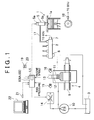
- FIG. 1 is a configuration diagram illustrating a fuel injection system of a diesel engine 1 according to the embodiment.
- the fuel injection system shown in FIG 1 is applied to a four-cylinder diesel engine 1, for example.
- the fuel injection system includes a common rail 2 serving as an accumulator that stores high-pressure fuel, a high-pressure fuel pump 4 that pressurizes fuel pumped out by a feed pump 10 from a fuel tank 3 and supplies the pressurized fuel to the common rail 2, an injector (fuel injection valve) 5 that injects the high-pressure fuel supplied from the common rail 2 into a cylinder (combustion chamber 1a) in the engine 1, and an electronic control unit 6 (hereinafter, referred to as an "ECU 6"), serving as a fuel injection amount control device that controls this fuel injection system.
- ECU 6 electronice control unit 6
- the ECU 6 sets a target fuel pressure, and the common rail 2 accumulates the high-pressure fuel supplied from the high-pressure fuel pump 4 at the target fuel pressure.
- a pressure sensor 7 that detects an accumulated fuel pressure (hereinafter, referred to as a "rail pressure") and outputs the detected rail pressure to the ECU 6, and a pressure limiter 8 that limits the rail pressure so as not to exceed a preset upper limit are attached to the common rail 2. When the rail pressure exceeds the upper limit, the pressure limiter 8 opens to vent the excess pressure to the fuel tank 3.
- the high-pressure fuel pump 4 is provided with a plunger 12 and a solenoid regulator valve 14.
- the plunger 12 reciprocates in a cylinder 11 in synchronization with the rotation of a camshaft 9 that is rotated by the drive force from a crankshaft of the engine 1.
- the solenoid regulator valve 14 regulates or adjusts the fuel amount drawn into a compression chamber 13 in the cylinder 11 from the feed pump 10.
- the solenoid regulator valve 14 regulates the fuel pumped out from the feed pump 10, and the fuel pushes open an inlet valve 15 to be drawn into the compression chamber 13.
- the solenoid regulator valve 14 is controlled by a control signal from the ECU 6 to vary the (cross-sectional) passage area of a fuel supply passage. By varying the passage area, the solenoid regulator valve 14 regulates or adjusts the amount of fuel introduced into the compression chamber 13 to adjust the discharge pressure of the fuel from the high-pressure fuel pump 4, thereby adjusting the rail pressure. More specifically, when fuel is not injected (during a fuel cut operation), such as when an accelerator angle is equal to "0,” the solenoid regulator valve 14 is fully closed. On the other hand, the solenoid regulator valve 14 is widely opened to increase the rail pressure.
- Each cylinder in the engine 1 is provided with an injector 5.
- the injector 5 is connected to the common rail 2 via a high-pressure pipe 17.
- the injector 5 includes a solenoid valve 5a that is operated based on a command from the ECU 6, and a nozzle 5b that injects a fuel when the solenoid valve 5a is energized.
- the solenoid valve 5a opens and closes a low-pressure passage that connects between a pressure chamber to which the high fuel pressure in the common rail 2 is applied and a low-pressure side. When the solenoid valve is energized, the low-pressure passage is opened. When the solenoid valve is de-energized, the low-pressure passage is closed.
- the nozzle 5b includes a needle that opens and closes a nozzle hole.
- the fuel pressure in the pressure chamber biases the needle in the valve closing direction (direction to close the nozzle hole). Therefore, when the low-pressure passage is opened by energizing the solenoid valve 5a and thereby the fuel pressure in the pressure chamber is reduced, the needle moves upward in the nozzle 5b to open the valve (open the nozzle hole) and the high-pressure fuel supplied from the common rail 2 is injected into the cylinder through the nozzle hole.
- An engine speed sensor 18 (for example, an electromagnetic pick up), an accelerator angle sensor 19, a pressure sensor 7 and the like are connected to the ECU 6.
- the engine speed sensor 18 outputs a pulse signal to calculate an engine speed.
- the accelerator angle sensor 19 detects an accelerator angle (an engine load).
- the pressure sensor 7 detects the rail pressure.
- the ECU 6 calculates a target rail pressure of the common rail 2 and an injection timing, injection amount, or the like appropriate for the operating condition of the engine 1 based on the information detected by the sensors 18, 19 and 7. Then, the ECU 6 electronically controls the solenoid regulator valve 14 of the high-pressure fuel pump 4 and the solenoid valve 5a of the injector 5 in accordance with the calculation result.
- a neutral switch 20 sends (inputs) a neutral signal to the ECU 6 when the shift position of the transmission is N (neutral) position.
- a clutch-off sensor 21 sends (inputs) a clutch-off signal to the ECU 6 when a vehicle driver depresses a clutch pedal.
- the ECU 6 further includes an interface to connect to a terminal device 22, and predetermined information (such as a vehicle travel distance described later) is input to the ECU 6 through the terminal device 22.
- a pilot injection with a very small amount of fuel is performed prior to the main injection performed at the beginning of an expansion stroke, and pilot injection amount learning control is performed to acquire an appropriate amount of the pilot injection.
- the ECU 6 stores a pilot injection amount setting map as shown in FIG. 2 in a ROM.
- the energization time of the injector appropriate for a certain common rail pressure is acquired in accordance with the pilot injection amount setting map, such that a command pilot injection amount, which is determined in accordance with an engine speed or the like, is acquired or achieved.
- pilot injection amount learning control a secular change in pilot injection amount of the injector 5 is learned, and the pilot injection amount of the injector 5 is corrected based on the learned value of the secular change.
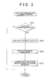
- step ST1 the ECU 6 determines whether a learning condition to perform pilot injection amount learning control during an operation of the engine 1 is satisfied. More specifically, the learning condition is satisfied if all of the following three conditions (1) - (3) are satisfied. (1) The accelerator angle is equal to "0.” (2) The shift position of the transmission is N (neutral) position or the clutch is off (disconnected). (3) A predetermined rail pressure is maintained.
- the ECU 6 determines the above-described conditions based on the outputs of the accelerator angle sensor 19, the neutral switch 20, the clutch-off sensor 21 and the pressure sensor 7. Note that the learning conditions for the pilot injection amount learning control are not limited to the above conditions, but may be set any other appropriate conditions.
- step ST1 determines whether the control routine is negative. If the determination in step ST1 is negative, this control routine is once ended. On the other hand, if the determination in step ST1 is affirmative, the process proceeds to step ST2.
- step ST2 a single injection with a very small amount of fuel (an amount same as the pilot injection amount, for example) is performed as a learning injection into a particular cylinder (a cylinder in which a piston is positioned near the top dead point). Then, in step ST3, the change in engine speed due to the single injection is detected. The change in engine speed is detected based on the output signal from the engine speed sensor 18.
- step ST4 the ECU 6 calculates the difference between a command fuel injection amount (a target injection amount determined by the ECU 6) and an actual fuel injection amount by the single injection.
- the difference (hereinafter, sometimes referred to as "deviation") between the command fuel injection amount and the actual fuel injection amount is set as a learned deviation (learned value).
- the pilot injection amount of the injector 5 is corrected based on the learned deviation.
- the ECU 6 compares the change in engine speed when a single injection with the command fuel injection amount is assumed to be performed (this change is stored in the memory in the ECU 6 in advance) with the change in actual engine speed corresponding to the actual fuel injection amount, and calculates the learned deviation (learned value) of the fuel injection amount from the difference in the engine speed.
- the pilot injection amount setting map (see FIG 2 ) described above is corrected based on the calculated learned deviation.
- multiple single injections may be performed (for example, 10 times) for each combination of a rail pressure and a cylinder to acquire multiple deviations between the command fuel injection amount and the actual fuel injection amount, and an average of the multiple deviations may be set as the learned deviation related to the combination of the rail pressure and the cylinder.
- the above-described pilot injection amount learning control is performed per cylinder per rail pressure.
- the pilot injection amount learning control ends. Thereafter, the pilot injection amount learning control is preformed at appropriate times, and the deviation (secular change) of the pilot injection amount due to the degradation of the injector 5 over time is appropriately calculated.
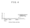
- the above-described pilot injection amount learning control is performed at such a frequency that the deviation in the pilot injection amount of the injector 5 does not exceed a predetermined injection amount correction accuracy line (for example, 0.2mm 3 ).
- a predetermined injection amount correction accuracy line for example, 0.2mm 3
- the horizontal axis indicates a vehicle travel distance
- the vertical axis indicates a deviation in the pilot injection amount of the injector 5.
- the zigzag line L1 indicates a deviation in the pilot injection amount of the injector 5 of a specific cylinder with a specific rail pressure.
- This zigzag line L1 indicates a case in which the pilot injection amount learning control is performed at an appropriate timing, that is, when the difference amount matches the injection amount correction accuracy line L2.
- the pilot injection amount is corrected such that the deviation is equal to zero at the vehicle travel distances 100km, 600km, 1600km and 3600km.
- the horizontal line indicates a vehicle travel distance
- the vertical line indicates the deviation and a learned deviation of the pilot injection amount of the injector 5.
- the curve L3 indicates an example of a deviation of the pilot injection amount of the injector 5 when the pilot injection amount learning control has never been performed.
- the line L4 indicates an integrated value of learned deviation shown in FIG 4 .
- the integrated value of the learned deviation at 100km, 600km, 1600km and 3600km are respectively 0.2mm 3 , 0.4mm 3 , 0.6mm 3 and 0.8mm 3 .
- Pilot injection amount correction control of the injector 5 when the ECU is replaced will be described hereinafter.
- the ECU 6 stores a degradation trend map L5 shown by a solid line in FIG 6 in the ROM.
- the degradation trend map L5 indicates a mean value of deviations (secular changes) in the pilot injection amount of the injector 5 estimated per vehicle travel distance when the pilot injection amount learning control has never been performed.
- the degradation trend map L5 indicates a relationship between the estimated secular change and the vehicle travel distance.
- the degradation trend map L5 may sometimes be referred to as an "estimated secular change information," hereinafter.
- the curve L6 shows the fastest secular change in the pilot injection amount, and the curve L7 shows the slowest secular change in the pilot injection amount.
- the deviation of the pilot injection amount of the injector 5 when the pilot injection amount has never been corrected by the pilot injection amount learning control falls between the curve L6 and the curve L7 in most cases, and results in a value close to the curve (degradation trend map) L5 with high probability.
- the curves L5 to L7 can be acquired in advance through experiments, or the like.
- the vehicle travel distance is, for example, 2800km.
- 0.6mm 3 is stored as an integrated value of learned deviation.
- an initial value (0mm 3 ) is stored as the integrated value of learned deviation. Therefore, if nothing is done, the deviation of the pilot injection amount of the degraded injector 5 is large and therefore a good pilot injection cannot be performed. In other words, because the pilot injection is performed according to a default pilot injection amount setting map corresponding to a new injector 5, the deviation increases and good pilot injection cannot be performed.
- the ECU 6 after the replacement calculates a temporary learned value of the pilot injection amount of the injector 5 in accordance with the degradation trend map L5 and a vehicle travel distance input from the terminal device 22, and corrects the pilot injection amount of the injector 5 using the temporary learned value instead of the default value until the first pilot injection amount learning control is completed after the replacement of the ECU 6.
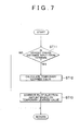
- the operation for correcting the pilot injection amount will be described hereinafter with reference to FIG. 7 .
- step ST11 the ECU 6 after the replacement (hereinafter, simply referred to as "ECU 6") determines whether a vehicle travel distance is input from the terminal device 22. If the determination in step ST11 is affirmative, the control process proceeds to step ST12. On the other hand, if the determination in step ST11 is negative, this control routine is once ended.
- step ST12 the ECU 6 calculates a temporary learned value of the pilot injection amount of the injector 5 (temporary integrated value of learned deviation) based on the input vehicle travel distance and the degradation trend map (estimated secular change information) L5.
- the ECU 6 acquires the value (deviation) on the degradation trend map L5 shown in FIG 6 corresponding to the input vehicle travel distance, as the temporary learned value.
- step ST13 the ECU 6 sets the calculated temporary learned value as the integrated value of the learned deviation (learned value) to be used in the correction of the pilot injection amount of the injector 5, and corrects the pilot injection amount of the injector 5 based on the temporary learned value.
- the ECU 6 corrects the pilot injection amount setting map (see FIG 2 ) using the temporary learned value as the integrated value of learned deviation.
- the correction of the pilot injection amount using the temporary learned value continues until the first pilot injection amount learning control is completed and the learned deviation is acquired through the first pilot injection amount leaning control.
- the integrated value of the learned deviation used to correct the pilot injection amount is updated from the temporary learned value to the learned value newly acquired by the first pilot injection amount learning control.
- the temporary learned value F is used as the integrated value of the learned deviation to correct the pilot injection amount until the first pilot injection amount learning control is completed after the ECU is replaced.
- the deviation of the pilot injection amount of the injector 5 is difference "a" between the value on the curve L6 and the temporary learned value F.
- the accuracy of the pilot injection amount improves significantly.
- the deviation of the pilot injection amount of the injector 5 changes over time along the curve L7
- the deviation in the pilot injection amount of the injector 5 after the correction is difference "c" between the value on the curve L7 and the temporary learned value F.
- the deviation of the conventional way is difference "d" between the value on the curve L7 and the default value. Therefore, the accuracy of the pilot injection amount does not much improve.
- the degradation trend map L5 indicates the mean value of the estimated deviations of the pilot injection amount of the injector 5 (for each vehicle travel distance) when the pilot injection amount learning control has never been performed
- the temporary learned value F calculated based on the degradation trend map L5 and the input vehicle travel distance is highly likely to be the value close to the integrated value of the learned deviation stored in the ECU before the replacement. Therefore, according to the ECU 6, in many cases, the degradation in accuracy of the pilot injection amount after the replacement of the ECU, which conventionally occurred, can be avoided.
- a second embodiment of the present invention will be described.
- the difference between the first embodiment and the second embodiment will be mainly described.
- Like elements are denoted by the like reference numerals in the drawings, and the description thereof will be omitted hereinafter.
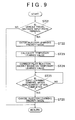
- the ECU 6 in the first embodiment is different from the ECU 6A in the second embodiment in a portion of the pilot injection amount correction control operation performed when the ECU is replaced. The difference is described with reference to the flowchart shown in FIG 9 .
- step ST21 the ECU 6A after replacement (hereinafter, simply referred to as "ECU 6A") determines whether a vehicle travel distance is input from the terminal device 22. If the determination in step ST21 is affirmative, the process proceeds to step ST22. On the other hand, if the determination in step ST21 is negative, this control routine is once ended.
- step ST22 the ECU 6A enters an injector learning priority mode.
- the ECU 6A executes the pilot injection amount learning control described with reference to FIG. 3 in priority to other learning processes, and execution frequency of the pilot injection amount learning control increases than before entering the injector learning priority mode.
- the other leaning processes means learning processes other than the pilot injection amount learning control operation, but shares an operation resource (ECU etc.) with the pilot injection amount learning control operation.
- the input of the vehicle travel distance from the terminal device 22 in step ST21 is used as an input of a command to enter the injector learning priority mode.
- the command to enter the injector learning priority mode may be input independently from the input of vehicle travel distance.
- Step ST23 is an operation similar to that of step ST12
- step ST24 is an operation similar to that of step ST13. Therefore, description thereof will be omitted here.
- step ST25 the ECU 6A determines whether the first pilot injection amount learning control after replacement of the ECU is completed. If the determination in step ST25 is affirmative, the process proceeds to step ST26. On the contrary, if the determination in step ST25 is negative, the determination in step ST25 is performed repeatedly.
- step ST26 the ECU 6A cancels (ends) the injector learning priority mode and ends this control routine.
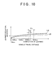
- the injector 5 can recover the most suitable injection state quickly after the replacement of the ECU.
- the ECU 6 in the first embodiment is different from the ECU 6B in the third embodiment in the pilot injection amount correction control operation when the ECU is replaced. The difference is described with reference to the flowchart shown in FIG. 11 .
- step ST31 the ECU 6B determines whether a predetermined command (command to enter the injector learning priority mode) is input from the terminal device 22. If the determination in step ST31 is affirmative, the process proceeds to step ST32. On the contrary, if the determination in step ST31 is negative, this control routine is once ended.
- a predetermined command command to enter the injector learning priority mode
- step ST32 the ECU 6B enters the injector learning priority mode.
- the ECU 6B executes the pilot injection amount learning control described above with reference to FIG. 3 in priority to other learning processes, and the execution frequency of the pilot injection amount learning control increases than before entering the injector learning priority mode.
- step ST33:YES when the first pilot injection amount learning control after replacement of ECU is completed (step ST33:YES), the injector learning priority mode is canceled in step ST34, and this control routine ends.
- the injector 5 can recover the most suitable injection state quickly after the replacement of the ECU.
- in-cylinder direct fuel injection engine in which fuel is directly injected into a combustion chamber from an injector is described as an example.
- an engine a port-injection engine in which fuel is injected into an intake pipe may be used, instead.
- an engine in which fuel is injected into both a combustion chamber and an intake pipe may be used.
- the present invention is not limited to a diesel engine; rather the present invention may be applied to the fuel injection in an in-cylinder direct injection gasoline engine or a port-injection gasoline engine.
- the injection amount learning control is performed for pilot injection.
- the present invention is not limited to the pilot injection. Rather, the injection amount learning control may be performed for main injection or after injection, which is performed after the main injection.
- the command to enter the injector learning priority mode may not be input from the terminal device 22.
- switches may be connected to the ECU 6A or 6B, and a predetermined switch signal input from the switches may be used as the command to enter the injector learning priority mode.
- the present invention may be used, for example, in a fuel injection amount control apparatus that performs learning control to correct secular change in a pilot injection amount of a diesel engine.
Landscapes
- Engineering & Computer Science (AREA)
- Chemical & Material Sciences (AREA)
- Combustion & Propulsion (AREA)
- Mechanical Engineering (AREA)
- General Engineering & Computer Science (AREA)
- Electrical Control Of Air Or Fuel Supplied To Internal-Combustion Engine (AREA)
- Combined Controls Of Internal Combustion Engines (AREA)
Abstract
Description
- This invention relates to a fuel injection amount control device and method for an internal combustion engine of a vehicle.
- An ECU (Electronic Control Unit) for an engine of a vehicle, such as an automobile, is available that learns a change in injection amount due to the degradation of an injector over time. Learned values are stored in a control memory in the ECU. When a failure occurs in the ECU, the ECU is removed and a new ECU is installed. In this case, while the injector stays in a condition degraded over time, the learned values of the injection amount of the injector that has been degraded over time is not stored in the control memory in the new ECU after the replacement. Therefore, it takes a while for the new ECU after the replacement to learn an appropriate injection amount of the injector degraded over time. Thus, it is difficult to make the injection amount of the injector optimum during the period (until the learning of the injection amount is completed).
- Japanese Patent Application Publication No.
2001-65399 JP-A-2001-65399 - Further, in an ECU system for a vehicle described in Japanese Patent Application Publication No.
2003-56398 JP-A-2003-56398 - Japanese Patent Application Publication No.
2001-349259 JP-A-2001-349259 - Japanese Patent Application Publication No.
2005-36788 JP-A-2005-36788 - In the method described in
JP-A-2001-65399 - In the ECU system for a vehicle described in
JP-A-2003-56398 - The present invention provides a fuel injection amount control device and method that quickly recover from a serious degradation of the fuel injection amount of the fuel injection valve that has been degraded over time, even if, when the ECU (a fuel injection amount control device) for a vehicle is replaced, the learned values regarding the fuel injection amount of the fuel injection valve stored in a memory in an ECU (a fuel injection amount control device) for a vehicle before the replacement is not carried over to a memory in an ECU for the vehicle after the replacement.
- A first aspect of the present invention provides a fuel injection amount control device that includes: learning means for learning a secular change in an injection amount of a fuel injection valve to acquire a learned value; correcting means for correcting the injection amount of the fuel injection valve based on the learned value acquired by the learning means; and temporary learned value calculating means for calculating a temporary learned value of the injection amount of the fuel injection valve based on an input travel distance of a vehicle and an estimated secular change information indicating the secular change in the injection amount of the fuel injection valve estimated per travel distance of the vehicle. The correcting means corrects the injection amount of the fuel injection valve based on the temporary learned value calculated by the temporary learned value calculating means instead of the learned value until the learning means completes an acquisition of the learned value after the travel distance is input.
- According to the first aspect of the present invention, for example, when a failure etc. occurs in the fuel injection amount control device and the fuel injection amount control device is replaced, the fuel injection amount control device after the replacement corrects the fuel injection amount of the fuel injection valve based on the temporary learned value after the replacement until the learning means completes the acquisition of the learned value. The estimated secular change information may be, for example, a mean value of empirically acquired secular changes in the injection amount of the fuel injection valve per travel distance, and such estimated secular change information may be stored in storage means in advance. By doing so, the degradation in the fuel injection amount of the fuel injection valve degraded over time can be reduced during the time period from the replacement of the fuel injection amount control device to the completion of acquisition of the learned value by the learning means in many cases.
- The fuel injection amount control device may further include fuel injection valve learning priority means for performing the learning by the learning means in priority to other learning after a command to enter a fuel injection valve learning priority mode is input until the learning by the learning means is completed and the learned value is acquired. The other learning here means learning other than the learning performed by the learning means, and is performed by learning control that shares an operation resource (CPU etc.) with the fuel injection amount control device. The command to enter a fuel injection valve learning priority mode may be the input of the travel distance.
- According to this construction, the time period in which the temporary learned value is used for correcting the fuel injection amount of the fuel injection valve is reduced, compared to the case where no entry into the fuel injection valve learning priority mode exists. As a result, the fuel injection valve can quickly recover the most appropriate injection state.
- A second aspect of the present invention provides a fuel injection amount control device that includes learning means for learning a secular change in an injection amount of a fuel injection valve to acquire a learned value; and correcting means for correcting the injection amount of the fuel injection valve based on the learned value acquired by the learning means. The fuel injection amount control device further includes fuel injection valve learning priority means for performing the learning by the learning means in priority to other learning after a command to enter a fuel injection valve learning priority mode is input until the learning by the learning means is completed and the learned value is acquired.
- According to the second aspect of the present invention, the time period in which a default value is used for correcting the fuel injection amount of the fuel injection valve is reduced, compared to the case where no entry into the fuel injection valve learning priority mode exists. As a result, the fuel injection valve can quickly recover the most appropriate injection state.
- A third aspect of the present invention provides a fuel injection amount control method. A secular change in an injection amount of a fuel injection valve is learned to acquire a learned value. The injection amount of the fuel injection valve is corrected based on the acquired learned value. A travel distance of a vehicle is input. A temporary learned value of the injection amount of the fuel injection valve is calculated based on the input travel distance and an estimated secular change information indicating the secular change in the injection amount of the fuel injection valve estimated per travel distance of the vehicle. The injection amount of the fuel injection valve is corrected based on the calculated temporary learned value instead of the learned value until the acquisition of the learned value is completed after the travel distance is input. According to the third aspect of the present invention, the effect similar to that of the first aspect of the present invention may be obtained.
- A fourth aspect of the present invention provides a fuel injection amount control method. in the method, a secular change in an injection amount of a fuel injection valve is learned to acquire a learned value. The injection amount of the fuel injection valve is corrected based on the acquired learned value. A command to enter a fuel injection valve learning priority mode is input. The learning of the secular change is performed in priority to other learning after the command to enter the fuel injection valve learning priority mode is input until the learning of the secular change is completed and the learned value is acquired. According to the fourth aspect of the present invention, the effect similar to that of the second aspect of the present invention may be obtained.
- The foregoing and further objects, features and advantages of the invention will become apparent from the following description of example embodiments with reference to the accompanying drawings, wherein like numerals are used to represent like elements and wherein:
-
FIG 1 is a configuration diagram illustrating a fuel injection system of a diesel engine according to an embodiment of the present invention; -
FIG. 2 is a diagram showing an example of a pilot injection amount setting map; -
FIG 3 is a flowchart showing a pilot injection amount learning control operation; -
FIG 4 is a diagram showing an example of a deviation of the pilot injection amount of the injector of a specific cylinder with a specific rail pressure; -
FIG 5 is a diagram showing an integrated value of learned deviation and a deviation of the pilot injection amount of an injector when no correction has been performed; -
FIG 6 is a diagram showing an example of a degradation trend map; -
FIG 7 is a flowchart showing a control operation of the ECU according to the first embodiment of the present invention; -
FIG 8 is a diagram showing an integrated value of learned deviation and a temporary learned value of the ECU according to the first embodiment of the present invention, and in particular, showing an example of a case where the ECU is replaced when the vehicle travel distance is 2800km; -
FIG 9 is a flowchart showing a control operation of the ECU according to a second embodiment of the present invention; -
FIG 10 is a diagram showing an integrated value of learned deviation and a temporary learned value of the ECU according to the second embodiment of the present invention, and in particular, showing an example of a case where the ECU is replaced when the vehicle travel distance is 2800km; -
FIG 11 is a flowchart showing a control operation of the ECU according to a third embodiment of the present invention; and -
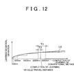
FIG 12 is a diagram showing an integrated value of learned deviation and a temporary learned value of the ECU according to the third embodiment of the present invention, and in particular, showing an example of a case where the ECU is replaced when the vehicle travel distance is 2800km. - A fuel injection amount control device according to a first embodiment of the present invention will be described hereinafter. In the embodiment, a fuel injection amount control device that is installed in a common-rail diesel engine (internal combustion engine) and performs learning control of a pilot injection amount (injection amount of a fuel injection valve), and a fuel injection system including the fuel injection amount control device are described as an example.
-
FIG. 1 is a configuration diagram illustrating a fuel injection system of adiesel engine 1 according to the embodiment. The fuel injection system shown inFIG 1 is applied to a four-cylinder diesel engine 1, for example. The fuel injection system includes acommon rail 2 serving as an accumulator that stores high-pressure fuel, a high-pressure fuel pump 4 that pressurizes fuel pumped out by afeed pump 10 from a fuel tank 3 and supplies the pressurized fuel to thecommon rail 2, an injector (fuel injection valve) 5 that injects the high-pressure fuel supplied from thecommon rail 2 into a cylinder (combustion chamber 1a) in theengine 1, and an electronic control unit 6 (hereinafter, referred to as an "ECU 6"), serving as a fuel injection amount control device that controls this fuel injection system. - The
ECU 6 sets a target fuel pressure, and thecommon rail 2 accumulates the high-pressure fuel supplied from the high-pressure fuel pump 4 at the target fuel pressure. Apressure sensor 7 that detects an accumulated fuel pressure (hereinafter, referred to as a "rail pressure") and outputs the detected rail pressure to theECU 6, and apressure limiter 8 that limits the rail pressure so as not to exceed a preset upper limit are attached to thecommon rail 2. When the rail pressure exceeds the upper limit, thepressure limiter 8 opens to vent the excess pressure to the fuel tank 3. - The high-
pressure fuel pump 4 is provided with aplunger 12 and asolenoid regulator valve 14. Theplunger 12 reciprocates in acylinder 11 in synchronization with the rotation of acamshaft 9 that is rotated by the drive force from a crankshaft of theengine 1. Thesolenoid regulator valve 14 regulates or adjusts the fuel amount drawn into acompression chamber 13 in thecylinder 11 from thefeed pump 10. In the high-pressure fuel pump 4, when theplunger 12 moves in thecylinder 11 from the top dead point to the bottom dead point, thesolenoid regulator valve 14 regulates the fuel pumped out from thefeed pump 10, and the fuel pushes open aninlet valve 15 to be drawn into thecompression chamber 13. Then, when theplunger 12 moves in thecylinder 11 from the bottom dead point to the top dead point, theplunger 12 pressurizes the fuel in thecompression chamber 13, and the pressurized fuel pushes open adischarge valve 16 to be pumped into thecommon rail 2. Thesolenoid regulator valve 14 is controlled by a control signal from theECU 6 to vary the (cross-sectional) passage area of a fuel supply passage. By varying the passage area, thesolenoid regulator valve 14 regulates or adjusts the amount of fuel introduced into thecompression chamber 13 to adjust the discharge pressure of the fuel from the high-pressure fuel pump 4, thereby adjusting the rail pressure. More specifically, when fuel is not injected (during a fuel cut operation), such as when an accelerator angle is equal to "0," thesolenoid regulator valve 14 is fully closed. On the other hand, thesolenoid regulator valve 14 is widely opened to increase the rail pressure. - Each cylinder in the
engine 1 is provided with aninjector 5. Theinjector 5 is connected to thecommon rail 2 via a high-pressure pipe 17. Theinjector 5 includes asolenoid valve 5a that is operated based on a command from theECU 6, and anozzle 5b that injects a fuel when thesolenoid valve 5a is energized. Thesolenoid valve 5a opens and closes a low-pressure passage that connects between a pressure chamber to which the high fuel pressure in thecommon rail 2 is applied and a low-pressure side. When the solenoid valve is energized, the low-pressure passage is opened. When the solenoid valve is de-energized, the low-pressure passage is closed. - The
nozzle 5b includes a needle that opens and closes a nozzle hole. The fuel pressure in the pressure chamber biases the needle in the valve closing direction (direction to close the nozzle hole). Therefore, when the low-pressure passage is opened by energizing thesolenoid valve 5a and thereby the fuel pressure in the pressure chamber is reduced, the needle moves upward in thenozzle 5b to open the valve (open the nozzle hole) and the high-pressure fuel supplied from thecommon rail 2 is injected into the cylinder through the nozzle hole. On the other hand, when the low-pressure passage is closed by de-energizing thesolenoid valve 5a, and thereby the fuel pressure in the pressure chamber is increased, the needle moves downward in thenozzle 5b to close the valve (close nozzle hole) and the injection ends. - An engine speed sensor 18 (for example, an electromagnetic pick up), an
accelerator angle sensor 19, apressure sensor 7 and the like are connected to theECU 6. Theengine speed sensor 18 outputs a pulse signal to calculate an engine speed. Theaccelerator angle sensor 19 detects an accelerator angle (an engine load). Thepressure sensor 7 detects the rail pressure. TheECU 6 calculates a target rail pressure of thecommon rail 2 and an injection timing, injection amount, or the like appropriate for the operating condition of theengine 1 based on the information detected by thesensors ECU 6 electronically controls thesolenoid regulator valve 14 of the high-pressure fuel pump 4 and thesolenoid valve 5a of theinjector 5 in accordance with the calculation result. - Further, a
neutral switch 20 sends (inputs) a neutral signal to theECU 6 when the shift position of the transmission is N (neutral) position. Also, a clutch-off sensor 21 sends (inputs) a clutch-off signal to theECU 6 when a vehicle driver depresses a clutch pedal. TheECU 6 further includes an interface to connect to aterminal device 22, and predetermined information (such as a vehicle travel distance described later) is input to theECU 6 through theterminal device 22. - In the fuel injection control performed by the
ECU 6, a pilot injection with a very small amount of fuel is performed prior to the main injection performed at the beginning of an expansion stroke, and pilot injection amount learning control is performed to acquire an appropriate amount of the pilot injection. By performing the pilot injection with a very small amount of fuel prior to the main injection, the temperature in thecombustion chamber 1a is lowered, fuel diffusion is enhanced during the main injection, and an ignition lag from fuel injection to ignition is shortened. As a result, combustion noises are reduced and NOx emission is reduced. - The
ECU 6 stores a pilot injection amount setting map as shown inFIG. 2 in a ROM. The pilot injection amount setting map defines relationships between a pilot injection amount and an energization time (valve opening time) respectively for multiple levels (six levels inFIG. 2 ) of common rail pressure (a - f inFIG 2 that are set such that, for example, a = 32MPa, b = 48MPa, c = 64MPa, d = 80MPa, e = 96MPa, f = 112MPa). The energization time of the injector appropriate for a certain common rail pressure is acquired in accordance with the pilot injection amount setting map, such that a command pilot injection amount, which is determined in accordance with an engine speed or the like, is acquired or achieved. - Next, a pilot injection amount learning control operation will be described with reference to the flowchart shown in
FIG. 3 . In the pilot injection amount learning control, a secular change in pilot injection amount of theinjector 5 is learned, and the pilot injection amount of theinjector 5 is corrected based on the learned value of the secular change. - In step ST1, the
ECU 6 determines whether a learning condition to perform pilot injection amount learning control during an operation of theengine 1 is satisfied. More specifically, the learning condition is satisfied if all of the following three conditions (1) - (3) are satisfied. (1) The accelerator angle is equal to "0." (2) The shift position of the transmission is N (neutral) position or the clutch is off (disconnected). (3) A predetermined rail pressure is maintained. - The
ECU 6 determines the above-described conditions based on the outputs of theaccelerator angle sensor 19, theneutral switch 20, the clutch-off sensor 21 and thepressure sensor 7. Note that the learning conditions for the pilot injection amount learning control are not limited to the above conditions, but may be set any other appropriate conditions. - If the determination in step ST1 is negative, this control routine is once ended. On the other hand, if the determination in step ST1 is affirmative, the process proceeds to step ST2.
- In step ST2, a single injection with a very small amount of fuel (an amount same as the pilot injection amount, for example) is performed as a learning injection into a particular cylinder (a cylinder in which a piston is positioned near the top dead point). Then, in step ST3, the change in engine speed due to the single injection is detected. The change in engine speed is detected based on the output signal from the
engine speed sensor 18. - In step ST4, the
ECU 6 calculates the difference between a command fuel injection amount (a target injection amount determined by the ECU 6) and an actual fuel injection amount by the single injection. The difference (hereinafter, sometimes referred to as "deviation") between the command fuel injection amount and the actual fuel injection amount is set as a learned deviation (learned value). Further, the pilot injection amount of theinjector 5 is corrected based on the learned deviation. In other words, theECU 6 compares the change in engine speed when a single injection with the command fuel injection amount is assumed to be performed (this change is stored in the memory in theECU 6 in advance) with the change in actual engine speed corresponding to the actual fuel injection amount, and calculates the learned deviation (learned value) of the fuel injection amount from the difference in the engine speed. Then, the pilot injection amount setting map (seeFIG 2 ) described above is corrected based on the calculated learned deviation. Preferably, multiple single injections may be performed (for example, 10 times) for each combination of a rail pressure and a cylinder to acquire multiple deviations between the command fuel injection amount and the actual fuel injection amount, and an average of the multiple deviations may be set as the learned deviation related to the combination of the rail pressure and the cylinder. - The above-described pilot injection amount learning control is performed per cylinder per rail pressure. When the steps ST1 to ST4 are performed for all cylinders and for all rail pressures (six rail pressures shown in
FIG 2 ), the pilot injection amount learning control ends. Thereafter, the pilot injection amount learning control is preformed at appropriate times, and the deviation (secular change) of the pilot injection amount due to the degradation of theinjector 5 over time is appropriately calculated. - The above-described pilot injection amount learning control is performed at such a frequency that the deviation in the pilot injection amount of the
injector 5 does not exceed a predetermined injection amount correction accuracy line (for example, 0.2mm3). InFIG. 4 , the horizontal axis indicates a vehicle travel distance, and the vertical axis indicates a deviation in the pilot injection amount of theinjector 5. The zigzag line L1 indicates a deviation in the pilot injection amount of theinjector 5 of a specific cylinder with a specific rail pressure. This zigzag line L1 indicates a case in which the pilot injection amount learning control is performed at an appropriate timing, that is, when the difference amount matches the injection amount correction accuracy line L2. Thus, the pilot injection amount is corrected such that the deviation is equal to zero at the vehicle travel distances 100km, 600km, 1600km and 3600km. - In
FIG 5 , the horizontal line indicates a vehicle travel distance, and the vertical line indicates the deviation and a learned deviation of the pilot injection amount of theinjector 5. More specifically, the curve L3 indicates an example of a deviation of the pilot injection amount of theinjector 5 when the pilot injection amount learning control has never been performed. The line L4 indicates an integrated value of learned deviation shown inFIG 4 . As shown in line L4, when the vehicle travel distances are 100km, 600km, 1600km and 3600km, the deviation of 0.2 mm3 is calculated as the learned deviation. In this case, the integrated value of the learned deviation at 100km, 600km, 1600km and 3600km are respectively 0.2mm3, 0.4mm3, 0.6mm3 and 0.8mm3. - Pilot injection amount correction control of the
injector 5 when the ECU is replaced will be described hereinafter. - The
ECU 6 stores a degradation trend map L5 shown by a solid line inFIG 6 in the ROM. The degradation trend map L5 indicates a mean value of deviations (secular changes) in the pilot injection amount of theinjector 5 estimated per vehicle travel distance when the pilot injection amount learning control has never been performed. Thus, the degradation trend map L5 indicates a relationship between the estimated secular change and the vehicle travel distance. The degradation trend map L5 may sometimes be referred to as an "estimated secular change information," hereinafter. The curve L6 shows the fastest secular change in the pilot injection amount, and the curve L7 shows the slowest secular change in the pilot injection amount. Therefore, the deviation of the pilot injection amount of theinjector 5 when the pilot injection amount has never been corrected by the pilot injection amount learning control falls between the curve L6 and the curve L7 in most cases, and results in a value close to the curve (degradation trend map) L5 with high probability. The curves L5 to L7 can be acquired in advance through experiments, or the like. - Hereinafter, an example when the secular change in the pilot injection amount progresses the most rapidly (the case of curve L6) will be described. In addition, in the following description, it is assumed that the curve L3 shown in
FIG 5 indicates the case where the secular change in the pilot injection amount progresses the most rapidly. - It is assumed that, when a failure occurs in the
ECU 6 installed on a vehicle and theECU 6 is replaced, the vehicle travel distance is, for example, 2800km. In this case, as shown inFIG. 5 , in the memory in theECU 6 before the replacement, 0.6mm3 is stored as an integrated value of learned deviation. However, in the memory of theECU 6 after the replacement, an initial value (0mm3) is stored as the integrated value of learned deviation. Therefore, if nothing is done, the deviation of the pilot injection amount of thedegraded injector 5 is large and therefore a good pilot injection cannot be performed. In other words, because the pilot injection is performed according to a default pilot injection amount setting map corresponding to anew injector 5, the deviation increases and good pilot injection cannot be performed. - Therefore, the
ECU 6 after the replacement calculates a temporary learned value of the pilot injection amount of theinjector 5 in accordance with the degradation trend map L5 and a vehicle travel distance input from theterminal device 22, and corrects the pilot injection amount of theinjector 5 using the temporary learned value instead of the default value until the first pilot injection amount learning control is completed after the replacement of theECU 6. The operation for correcting the pilot injection amount will be described hereinafter with reference toFIG. 7 . - In step ST11, the
ECU 6 after the replacement (hereinafter, simply referred to as "ECU 6") determines whether a vehicle travel distance is input from theterminal device 22. If the determination in step ST11 is affirmative, the control process proceeds to step ST12. On the other hand, if the determination in step ST11 is negative, this control routine is once ended. - In step ST12, the
ECU 6 calculates a temporary learned value of the pilot injection amount of the injector 5 (temporary integrated value of learned deviation) based on the input vehicle travel distance and the degradation trend map (estimated secular change information) L5. In other words, theECU 6 acquires the value (deviation) on the degradation trend map L5 shown inFIG 6 corresponding to the input vehicle travel distance, as the temporary learned value. - In step ST13, the
ECU 6 sets the calculated temporary learned value as the integrated value of the learned deviation (learned value) to be used in the correction of the pilot injection amount of theinjector 5, and corrects the pilot injection amount of theinjector 5 based on the temporary learned value. In other words, theECU 6 corrects the pilot injection amount setting map (seeFIG 2 ) using the temporary learned value as the integrated value of learned deviation. The correction of the pilot injection amount using the temporary learned value continues until the first pilot injection amount learning control is completed and the learned deviation is acquired through the first pilot injection amount leaning control. Incidentally, when the first pilot injection amount learning control is completed after the replacement of the ECU, the integrated value of the learned deviation used to correct the pilot injection amount is updated from the temporary learned value to the learned value newly acquired by the first pilot injection amount learning control. - According to the
ECU 6 described above, as shown inFIG 8 , the temporary learned value F is used as the integrated value of the learned deviation to correct the pilot injection amount until the first pilot injection amount learning control is completed after the ECU is replaced. Thus, during this period, the deviation of the pilot injection amount of theinjector 5 is difference "a" between the value on the curve L6 and the temporary learned value F. Compared to the conventional case in which the deviation of the pilot injection amount of theinjector 5 after replacement of the ECU is difference "b" between the value on the curve L6 and the default value, the accuracy of the pilot injection amount improves significantly. - In the meantime, if the deviation of the pilot injection amount of the
injector 5 changes over time along the curve L7, the deviation in the pilot injection amount of theinjector 5 after the correction is difference "c" between the value on the curve L7 and the temporary learned value F. In this case, the deviation of the conventional way is difference "d" between the value on the curve L7 and the default value. Therefore, the accuracy of the pilot injection amount does not much improve. However, because the degradation trend map L5 indicates the mean value of the estimated deviations of the pilot injection amount of the injector 5 (for each vehicle travel distance) when the pilot injection amount learning control has never been performed, the temporary learned value F calculated based on the degradation trend map L5 and the input vehicle travel distance is highly likely to be the value close to the integrated value of the learned deviation stored in the ECU before the replacement. Therefore, according to theECU 6, in many cases, the degradation in accuracy of the pilot injection amount after the replacement of the ECU, which conventionally occurred, can be avoided. - A second embodiment of the present invention will be described. In the second embodiment, the difference between the first embodiment and the second embodiment will be mainly described. Like elements are denoted by the like reference numerals in the drawings, and the description thereof will be omitted hereinafter.
- The
ECU 6 in the first embodiment is different from theECU 6A in the second embodiment in a portion of the pilot injection amount correction control operation performed when the ECU is replaced. The difference is described with reference to the flowchart shown inFIG 9 . - In step ST21, the
ECU 6A after replacement (hereinafter, simply referred to as "ECU 6A") determines whether a vehicle travel distance is input from theterminal device 22. If the determination in step ST21 is affirmative, the process proceeds to step ST22. On the other hand, if the determination in step ST21 is negative, this control routine is once ended. - In step ST22, the
ECU 6A enters an injector learning priority mode. In the injector learning priority mode, theECU 6A executes the pilot injection amount learning control described with reference toFIG. 3 in priority to other learning processes, and execution frequency of the pilot injection amount learning control increases than before entering the injector learning priority mode. The other leaning processes means learning processes other than the pilot injection amount learning control operation, but shares an operation resource (ECU etc.) with the pilot injection amount learning control operation. Incidentally, in this embodiment, the input of the vehicle travel distance from theterminal device 22 in step ST21 is used as an input of a command to enter the injector learning priority mode. However, the command to enter the injector learning priority mode may be input independently from the input of vehicle travel distance. - Step ST23 is an operation similar to that of step ST12, and step ST24 is an operation similar to that of step ST13. Therefore, description thereof will be omitted here.
- In step ST25, the
ECU 6A determines whether the first pilot injection amount learning control after replacement of the ECU is completed. If the determination in step ST25 is affirmative, the process proceeds to step ST26. On the contrary, if the determination in step ST25 is negative, the determination in step ST25 is performed repeatedly. - In step ST26, the
ECU 6A cancels (ends) the injector learning priority mode and ends this control routine. - According to the
ECU 6A, as shown inFIG 10 , the time period T2 in which the temporary learned value is used to correct the pilot injection amount is reduced, compared to the same time period T1 in the case where the ECU does not enter the injector learning priority mode. Therefore, theinjector 5 can recover the most suitable injection state quickly after the replacement of the ECU. - A third embodiment of the present invention will be described hereinafter. In the following description, the difference between the first embodiment and the third embodiment will be mainly described. In the drawings, like elements will be denoted by like reference numerals, and the description thereof will be omitted.
- The
ECU 6 in the first embodiment is different from theECU 6B in the third embodiment in the pilot injection amount correction control operation when the ECU is replaced. The difference is described with reference to the flowchart shown inFIG. 11 . - In step ST31, the
ECU 6B determines whether a predetermined command (command to enter the injector learning priority mode) is input from theterminal device 22. If the determination in step ST31 is affirmative, the process proceeds to step ST32. On the contrary, if the determination in step ST31 is negative, this control routine is once ended. - In step ST32, the
ECU 6B enters the injector learning priority mode. In the injector learning priority mode, theECU 6B executes the pilot injection amount learning control described above with reference toFIG. 3 in priority to other learning processes, and the execution frequency of the pilot injection amount learning control increases than before entering the injector learning priority mode. - Then, when the first pilot injection amount learning control after replacement of ECU is completed (step ST33:YES), the injector learning priority mode is canceled in step ST34, and this control routine ends.
- According to the
ECU 6B, as shown inFIG. 12 , the time period T3 in which the default value (0) is used to correct the pilot injection amount is reduced, compared to the same time period T1 in the case where the ECU does not enter the injector learning priority mode. Therefore, theinjector 5 can recover the most suitable injection state quickly after the replacement of the ECU. - In the above-described first to third embodiments, in-cylinder direct fuel injection engine in which fuel is directly injected into a combustion chamber from an injector is described as an example. However, an engine (a port-injection engine) in which fuel is injected into an intake pipe may be used, instead. In addition, an engine in which fuel is injected into both a combustion chamber and an intake pipe may be used. Further, the present invention is not limited to a diesel engine; rather the present invention may be applied to the fuel injection in an in-cylinder direct injection gasoline engine or a port-injection gasoline engine.
- Furthermore, in the above-described first to third embodiments, the injection amount learning control is performed for pilot injection. However, the present invention is not limited to the pilot injection. Rather, the injection amount learning control may be performed for main injection or after injection, which is performed after the main injection.
- In addition, the command to enter the injector learning priority mode may not be input from the
terminal device 22. For example, switches may be connected to theECU - The present invention may be used, for example, in a fuel injection amount control apparatus that performs learning control to correct secular change in a pilot injection amount of a diesel engine.
- While some embodiments of the invention have been illustrated above, it is to be understood that the invention is not limited to details of the illustrated embodiments, but may be embodied with various changes, modifications or improvements, which may occur to those skilled in the art, without departing from the spirit and scope of the invention.
Claims (7)
- A fuel injection amount control device (6, 6A) characterized by comprising:learning means for learning a secular change in an injection amount of a fuel injection valve (5) to acquire a learned value;correcting means for correcting the injection amount of the fuel injection valve based on the learned value acquired by the learning means; andtemporary learned value calculating means for calculating a temporary learned value of the injection amount of the fuel injection valve based on an input travel distance of a vehicle and an estimated secular change information (L5) indicating the secular change in the injection amount of the fuel injection valve estimated per travel distance of the vehicle,wherein the correcting means corrects the injection amount of the fuel injection valve based on the temporary learned value calculated by the temporary learned value calculating means instead of the learned value until the learning means completes an acquisition of the learned value after the travel distance is input.
- The fuel injection amount control device according to claim 1, further comprising fuel injection valve learning priority means for performing the learning by the learning means in priority to other learning after a command to enter a fuel injection valve learning priority mode is input until the learning by the learning means is completed and the learned value is acquired.
- The fuel injection amount control device according to claim 1 or 2, wherein the estimated secular change information is a mean value of empirically acquired secular changes in the injection amount of the fuel injection valve per travel distance, and the fuel injection amount control device further comprises storage means that stores the estimated secular change information in advance.
- The fuel injection amount control device according to claim 2, wherein the command to enter the fuel injection valve learning priority mode is the input of the travel distance.
- A fuel injection amount control device (6B) characterized by comprising:learning means for learning a secular change in an injection amount of a fuel injection valve (5) to acquire a learned value;correcting means for correcting the injection amount of the fuel injection valve based on the learned value acquired by the learning means; andfuel injection valve learning priority means for performing the learning by the learning means in priority to other learning after a command to enter a fuel injection valve learning priority mode is input until the learning by the learning means is completed and the learned value is acquired.
- A fuel injection amount control method characterized by comprising the steps of:learning a secular change in an injection amount of a fuel injection valve to acquire a learned value;correcting the injection amount of the fuel injection valve based on the acquired learned value;inputting a travel distance of a vehicle (ST11, ST12);calculating a temporary learned value of the injection amount of the fuel injection valve based the input travel distance and an estimated secular change information indicating the secular change in the injection amount of the fuel injection valve estimated per travel distance of the vehicle (ST12, ST23); andcorrecting the injection amount of the fuel injection valve based on the calculated temporary learned value instead of the learned value until the acquisition of the learned value is completed after the travel distance is input (ST13, ST24).
- A fuel injection amount control method characterized by comprising the steps of:learning a secular change in an injection amount of a fuel injection valve to acquire a learned value;correcting the injection amount of the fuel injection valve based on the acquired learned value;inputting a command to enter a fuel injection valve learning priority mode (ST31); andperforming the learning of the secular change in priority to other learning after the command to enter the fuel injection valve learning priority mode is input until the learning of the secular change is completed and the learned value is acquired (ST32, ST33).
Applications Claiming Priority (1)
| Application Number | Priority Date | Filing Date | Title |
|---|---|---|---|
| JP2008121400A JP4737227B2 (en) | 2008-05-07 | 2008-05-07 | Fuel injection amount control device |
Publications (3)
| Publication Number | Publication Date |
|---|---|
| EP2116708A2 true EP2116708A2 (en) | 2009-11-11 |
| EP2116708A3 EP2116708A3 (en) | 2017-03-29 |
| EP2116708B1 EP2116708B1 (en) | 2019-02-20 |
Family
ID=40863674
Family Applications (1)
| Application Number | Title | Priority Date | Filing Date |
|---|---|---|---|
| EP09251255.7A Not-in-force EP2116708B1 (en) | 2008-05-07 | 2009-05-05 | Fuel injection amount control device and method |
Country Status (2)
| Country | Link |
|---|---|
| EP (1) | EP2116708B1 (en) |
| JP (1) | JP4737227B2 (en) |
Cited By (1)
| Publication number | Priority date | Publication date | Assignee | Title |
|---|---|---|---|---|
| FR3047044A1 (en) * | 2016-01-21 | 2017-07-28 | Continental Automotive France | METHOD FOR MANAGING THE DRIFT OF AN INJECTOR OF A MOTOR VEHICLE ENGINE |
Families Citing this family (2)
| Publication number | Priority date | Publication date | Assignee | Title |
|---|---|---|---|---|
| JP5256922B2 (en) * | 2008-08-08 | 2013-08-07 | トヨタ自動車株式会社 | Injection quantity control device for internal combustion engine |
| JP7560987B2 (en) * | 2020-10-09 | 2024-10-03 | 株式会社Subaru | Engine Control Unit |
Family Cites Families (9)
| Publication number | Priority date | Publication date | Assignee | Title |
|---|---|---|---|---|
| JPH06146988A (en) * | 1992-11-13 | 1994-05-27 | Toyota Motor Corp | Learning value control device for internal combustion engine |
| JP4543588B2 (en) * | 2000-07-14 | 2010-09-15 | トヨタ自動車株式会社 | Engine fuel injection control device |
| JP4016633B2 (en) * | 2001-10-19 | 2007-12-05 | 日産自動車株式会社 | Fuel injection control device for internal combustion engine |
| JP4089244B2 (en) * | 2002-03-01 | 2008-05-28 | 株式会社デンソー | Injection amount control device for internal combustion engine |
| JP4218496B2 (en) * | 2003-11-05 | 2009-02-04 | 株式会社デンソー | Injection quantity control device for internal combustion engine |
| JP2007332816A (en) * | 2006-06-13 | 2007-12-27 | Denso Corp | Fuel injection control device |
| DE102006032245B4 (en) * | 2006-07-12 | 2008-11-06 | Continental Automotive Gmbh | Adaptation method of an injection system of an internal combustion engine |
| JP4788557B2 (en) * | 2006-10-17 | 2011-10-05 | 株式会社デンソー | Fuel injection control device |
| JP4840397B2 (en) * | 2008-04-23 | 2011-12-21 | トヨタ自動車株式会社 | Fuel injection amount learning control device |
-
2008
- 2008-05-07 JP JP2008121400A patent/JP4737227B2/en not_active Expired - Fee Related
-
2009
- 2009-05-05 EP EP09251255.7A patent/EP2116708B1/en not_active Not-in-force
Cited By (1)
| Publication number | Priority date | Publication date | Assignee | Title |
|---|---|---|---|---|
| FR3047044A1 (en) * | 2016-01-21 | 2017-07-28 | Continental Automotive France | METHOD FOR MANAGING THE DRIFT OF AN INJECTOR OF A MOTOR VEHICLE ENGINE |
Also Published As
| Publication number | Publication date |
|---|---|
| EP2116708A3 (en) | 2017-03-29 |
| EP2116708B1 (en) | 2019-02-20 |
| JP4737227B2 (en) | 2011-07-27 |
| JP2009270481A (en) | 2009-11-19 |
Similar Documents
| Publication | Publication Date | Title |
|---|---|---|
| EP2045458B1 (en) | Defective injection detection device and fuel injection system having the same | |
| JP4775342B2 (en) | Fuel injection control device and fuel injection system using the same | |
| JP4424395B2 (en) | Fuel injection control device for internal combustion engine | |
| US7552709B2 (en) | Accumulator fuel injection apparatus compensating for injector individual variability | |
| US7599784B2 (en) | Fuel injection system learning average of injection quantities for correcting injection characteristic of fuel injector | |
| US7316220B2 (en) | Actuator drive system and fuel injection system | |
| EP1978226B1 (en) | Control apparatus for precisely controlling fuel injection apparatus at varying accumulator fuel pressure | |
| US7725241B2 (en) | Fuel injection control device and fuel injection system using the same | |
| US6990950B2 (en) | Fuel injection system of internal combustion engine | |
| JP2013177823A (en) | Fuel leakage detection apparatus | |
| CN101473128B (en) | Method and device for matching characteristics of injector valves | |
| US8833147B2 (en) | Diagnostic apparatus for fuel injector | |
| JP4685638B2 (en) | Fuel injection amount control device and internal combustion engine equipped with the control device | |
| EP2116708B1 (en) | Fuel injection amount control device and method | |
| JP2013177824A (en) | Detection device for continued injection of fuel | |
| JP4513895B2 (en) | Fuel injection system control device | |
| US9267459B2 (en) | Fuel-injector-replacement determining device | |
| JP2009057898A (en) | Fuel injection control device for internal combustion engine | |
| JP6252327B2 (en) | Fuel supply control device | |
| JP4529892B2 (en) | Fuel injection control device for multi-cylinder engine | |
| JP5821666B2 (en) | Fuel pump control device | |
| JP7021597B2 (en) | Fuel injection system |
Legal Events
| Date | Code | Title | Description |
|---|---|---|---|
| PUAI | Public reference made under article 153(3) epc to a published international application that has entered the european phase |
Free format text: ORIGINAL CODE: 0009012 |
|
| 17P | Request for examination filed |
Effective date: 20090523 |
|
| AK | Designated contracting states |
Kind code of ref document: A2 Designated state(s): AT BE BG CH CY CZ DE DK EE ES FI FR GB GR HR HU IE IS IT LI LT LU LV MC MK MT NL NO PL PT RO SE SI SK TR |
|
| RAP1 | Party data changed (applicant data changed or rights of an application transferred) |
Owner name: TOYOTA JIDOSHA KABUSHIKI KAISHA |
|
| PUAL | Search report despatched |
Free format text: ORIGINAL CODE: 0009013 |
|
| AK | Designated contracting states |
Kind code of ref document: A3 Designated state(s): AT BE BG CH CY CZ DE DK EE ES FI FR GB GR HR HU IE IS IT LI LT LU LV MC MK MT NL NO PL PT RO SE SI SK TR |
|
| AX | Request for extension of the european patent |
Extension state: AL BA RS |
|
| RIC1 | Information provided on ipc code assigned before grant |
Ipc: F02D 43/02 20060101ALI20170218BHEP Ipc: F02D 41/24 20060101ALI20170218BHEP Ipc: F02D 41/00 20060101ALI20170218BHEP Ipc: F02D 41/14 20060101AFI20170218BHEP |
|
| STAA | Information on the status of an ep patent application or granted ep patent |
Free format text: STATUS: EXAMINATION IS IN PROGRESS |
|
| 17Q | First examination report despatched |
Effective date: 20180209 |
|
| GRAP | Despatch of communication of intention to grant a patent |
Free format text: ORIGINAL CODE: EPIDOSNIGR1 |
|
| STAA | Information on the status of an ep patent application or granted ep patent |
Free format text: STATUS: GRANT OF PATENT IS INTENDED |
|
| INTG | Intention to grant announced |
Effective date: 20181005 |
|
| GRAS | Grant fee paid |
Free format text: ORIGINAL CODE: EPIDOSNIGR3 |
|
| GRAA | (expected) grant |
Free format text: ORIGINAL CODE: 0009210 |
|
| STAA | Information on the status of an ep patent application or granted ep patent |
Free format text: STATUS: THE PATENT HAS BEEN GRANTED |
|
| AK | Designated contracting states |
Kind code of ref document: B1 Designated state(s): AT BE BG CH CY CZ DE DK EE ES FI FR GB GR HR HU IE IS IT LI LT LU LV MC MK MT NL NO PL PT RO SE SI SK TR |
|
| REG | Reference to a national code |
Ref country code: GB Ref legal event code: FG4D |
|
| REG | Reference to a national code |
Ref country code: CH Ref legal event code: EP |
|
| REG | Reference to a national code |
Ref country code: DE Ref legal event code: R096 Ref document number: 602009057038 Country of ref document: DE |
|
| REG | Reference to a national code |
Ref country code: AT Ref legal event code: REF Ref document number: 1098506 Country of ref document: AT Kind code of ref document: T Effective date: 20190315 |
|
| REG | Reference to a national code |
Ref country code: IE Ref legal event code: FG4D |
|
| REG | Reference to a national code |
Ref country code: LT Ref legal event code: MG4D Ref country code: DE Ref legal event code: R084 Ref document number: 602009057038 Country of ref document: DE |
|
| REG | Reference to a national code |
Ref country code: NL Ref legal event code: MP Effective date: 20190220 |
|
| PG25 | Lapsed in a contracting state [announced via postgrant information from national office to epo] |
Ref country code: FI Free format text: LAPSE BECAUSE OF FAILURE TO SUBMIT A TRANSLATION OF THE DESCRIPTION OR TO PAY THE FEE WITHIN THE PRESCRIBED TIME-LIMIT Effective date: 20190220 Ref country code: NO Free format text: LAPSE BECAUSE OF FAILURE TO SUBMIT A TRANSLATION OF THE DESCRIPTION OR TO PAY THE FEE WITHIN THE PRESCRIBED TIME-LIMIT Effective date: 20190520 Ref country code: PT Free format text: LAPSE BECAUSE OF FAILURE TO SUBMIT A TRANSLATION OF THE DESCRIPTION OR TO PAY THE FEE WITHIN THE PRESCRIBED TIME-LIMIT Effective date: 20190620 Ref country code: SE Free format text: LAPSE BECAUSE OF FAILURE TO SUBMIT A TRANSLATION OF THE DESCRIPTION OR TO PAY THE FEE WITHIN THE PRESCRIBED TIME-LIMIT Effective date: 20190220 Ref country code: LT Free format text: LAPSE BECAUSE OF FAILURE TO SUBMIT A TRANSLATION OF THE DESCRIPTION OR TO PAY THE FEE WITHIN THE PRESCRIBED TIME-LIMIT Effective date: 20190220 |
|
| PG25 | Lapsed in a contracting state [announced via postgrant information from national office to epo] |
Ref country code: HR Free format text: LAPSE BECAUSE OF FAILURE TO SUBMIT A TRANSLATION OF THE DESCRIPTION OR TO PAY THE FEE WITHIN THE PRESCRIBED TIME-LIMIT Effective date: 20190220 Ref country code: NL Free format text: LAPSE BECAUSE OF FAILURE TO SUBMIT A TRANSLATION OF THE DESCRIPTION OR TO PAY THE FEE WITHIN THE PRESCRIBED TIME-LIMIT Effective date: 20190220 Ref country code: IS Free format text: LAPSE BECAUSE OF FAILURE TO SUBMIT A TRANSLATION OF THE DESCRIPTION OR TO PAY THE FEE WITHIN THE PRESCRIBED TIME-LIMIT Effective date: 20190620 Ref country code: BG Free format text: LAPSE BECAUSE OF FAILURE TO SUBMIT A TRANSLATION OF THE DESCRIPTION OR TO PAY THE FEE WITHIN THE PRESCRIBED TIME-LIMIT Effective date: 20190520 Ref country code: GR Free format text: LAPSE BECAUSE OF FAILURE TO SUBMIT A TRANSLATION OF THE DESCRIPTION OR TO PAY THE FEE WITHIN THE PRESCRIBED TIME-LIMIT Effective date: 20190521 Ref country code: LV Free format text: LAPSE BECAUSE OF FAILURE TO SUBMIT A TRANSLATION OF THE DESCRIPTION OR TO PAY THE FEE WITHIN THE PRESCRIBED TIME-LIMIT Effective date: 20190220 |
|
| REG | Reference to a national code |
Ref country code: AT Ref legal event code: MK05 Ref document number: 1098506 Country of ref document: AT Kind code of ref document: T Effective date: 20190220 |
|
| PG25 | Lapsed in a contracting state [announced via postgrant information from national office to epo] |
Ref country code: EE Free format text: LAPSE BECAUSE OF FAILURE TO SUBMIT A TRANSLATION OF THE DESCRIPTION OR TO PAY THE FEE WITHIN THE PRESCRIBED TIME-LIMIT Effective date: 20190220 Ref country code: DK Free format text: LAPSE BECAUSE OF FAILURE TO SUBMIT A TRANSLATION OF THE DESCRIPTION OR TO PAY THE FEE WITHIN THE PRESCRIBED TIME-LIMIT Effective date: 20190220 Ref country code: IT Free format text: LAPSE BECAUSE OF FAILURE TO SUBMIT A TRANSLATION OF THE DESCRIPTION OR TO PAY THE FEE WITHIN THE PRESCRIBED TIME-LIMIT Effective date: 20190220 Ref country code: CZ Free format text: LAPSE BECAUSE OF FAILURE TO SUBMIT A TRANSLATION OF THE DESCRIPTION OR TO PAY THE FEE WITHIN THE PRESCRIBED TIME-LIMIT Effective date: 20190220 Ref country code: RO Free format text: LAPSE BECAUSE OF FAILURE TO SUBMIT A TRANSLATION OF THE DESCRIPTION OR TO PAY THE FEE WITHIN THE PRESCRIBED TIME-LIMIT Effective date: 20190220 Ref country code: SK Free format text: LAPSE BECAUSE OF FAILURE TO SUBMIT A TRANSLATION OF THE DESCRIPTION OR TO PAY THE FEE WITHIN THE PRESCRIBED TIME-LIMIT Effective date: 20190220 Ref country code: ES Free format text: LAPSE BECAUSE OF FAILURE TO SUBMIT A TRANSLATION OF THE DESCRIPTION OR TO PAY THE FEE WITHIN THE PRESCRIBED TIME-LIMIT Effective date: 20190220 |
|
| REG | Reference to a national code |
Ref country code: DE Ref legal event code: R097 Ref document number: 602009057038 Country of ref document: DE |
|
| PG25 | Lapsed in a contracting state [announced via postgrant information from national office to epo] |
Ref country code: PL Free format text: LAPSE BECAUSE OF FAILURE TO SUBMIT A TRANSLATION OF THE DESCRIPTION OR TO PAY THE FEE WITHIN THE PRESCRIBED TIME-LIMIT Effective date: 20190220 |
|
| PLBE | No opposition filed within time limit |
Free format text: ORIGINAL CODE: 0009261 |
|
| STAA | Information on the status of an ep patent application or granted ep patent |
Free format text: STATUS: NO OPPOSITION FILED WITHIN TIME LIMIT |
|
| REG | Reference to a national code |
Ref country code: CH Ref legal event code: PL |
|
| PG25 | Lapsed in a contracting state [announced via postgrant information from national office to epo] |
Ref country code: AT Free format text: LAPSE BECAUSE OF FAILURE TO SUBMIT A TRANSLATION OF THE DESCRIPTION OR TO PAY THE FEE WITHIN THE PRESCRIBED TIME-LIMIT Effective date: 20190220 |
|
| 26N | No opposition filed |
Effective date: 20191121 |
|
| GBPC | Gb: european patent ceased through non-payment of renewal fee |
Effective date: 20190520 |
|
| PG25 | Lapsed in a contracting state [announced via postgrant information from national office to epo] |
Ref country code: LI Free format text: LAPSE BECAUSE OF NON-PAYMENT OF DUE FEES Effective date: 20190531 Ref country code: CH Free format text: LAPSE BECAUSE OF NON-PAYMENT OF DUE FEES Effective date: 20190531 Ref country code: MC Free format text: LAPSE BECAUSE OF FAILURE TO SUBMIT A TRANSLATION OF THE DESCRIPTION OR TO PAY THE FEE WITHIN THE PRESCRIBED TIME-LIMIT Effective date: 20190220 |
|
| REG | Reference to a national code |
Ref country code: BE Ref legal event code: MM Effective date: 20190531 |
|
| PG25 | Lapsed in a contracting state [announced via postgrant information from national office to epo] |
Ref country code: SI Free format text: LAPSE BECAUSE OF FAILURE TO SUBMIT A TRANSLATION OF THE DESCRIPTION OR TO PAY THE FEE WITHIN THE PRESCRIBED TIME-LIMIT Effective date: 20190220 Ref country code: LU Free format text: LAPSE BECAUSE OF NON-PAYMENT OF DUE FEES Effective date: 20190505 |
|
| PG25 | Lapsed in a contracting state [announced via postgrant information from national office to epo] |
Ref country code: TR Free format text: LAPSE BECAUSE OF FAILURE TO SUBMIT A TRANSLATION OF THE DESCRIPTION OR TO PAY THE FEE WITHIN THE PRESCRIBED TIME-LIMIT Effective date: 20190220 |
|
| PG25 | Lapsed in a contracting state [announced via postgrant information from national office to epo] |
Ref country code: GB Free format text: LAPSE BECAUSE OF NON-PAYMENT OF DUE FEES Effective date: 20190520 Ref country code: IE Free format text: LAPSE BECAUSE OF NON-PAYMENT OF DUE FEES Effective date: 20190505 |
|
| PG25 | Lapsed in a contracting state [announced via postgrant information from national office to epo] |
Ref country code: BE Free format text: LAPSE BECAUSE OF NON-PAYMENT OF DUE FEES Effective date: 20190531 |
|
| PG25 | Lapsed in a contracting state [announced via postgrant information from national office to epo] |
Ref country code: FR Free format text: LAPSE BECAUSE OF NON-PAYMENT OF DUE FEES Effective date: 20190531 |
|
| PG25 | Lapsed in a contracting state [announced via postgrant information from national office to epo] |
Ref country code: CY Free format text: LAPSE BECAUSE OF FAILURE TO SUBMIT A TRANSLATION OF THE DESCRIPTION OR TO PAY THE FEE WITHIN THE PRESCRIBED TIME-LIMIT Effective date: 20190220 |
|
| PG25 | Lapsed in a contracting state [announced via postgrant information from national office to epo] |
Ref country code: HU Free format text: LAPSE BECAUSE OF FAILURE TO SUBMIT A TRANSLATION OF THE DESCRIPTION OR TO PAY THE FEE WITHIN THE PRESCRIBED TIME-LIMIT; INVALID AB INITIO Effective date: 20090505 Ref country code: MT Free format text: LAPSE BECAUSE OF FAILURE TO SUBMIT A TRANSLATION OF THE DESCRIPTION OR TO PAY THE FEE WITHIN THE PRESCRIBED TIME-LIMIT Effective date: 20190220 |
|
| PGFP | Annual fee paid to national office [announced via postgrant information from national office to epo] |
Ref country code: DE Payment date: 20210408 Year of fee payment: 13 |
|
| PG25 | Lapsed in a contracting state [announced via postgrant information from national office to epo] |
Ref country code: MK Free format text: LAPSE BECAUSE OF FAILURE TO SUBMIT A TRANSLATION OF THE DESCRIPTION OR TO PAY THE FEE WITHIN THE PRESCRIBED TIME-LIMIT Effective date: 20190220 |
|
| REG | Reference to a national code |
Ref country code: DE Ref legal event code: R119 Ref document number: 602009057038 Country of ref document: DE |
|
| PG25 | Lapsed in a contracting state [announced via postgrant information from national office to epo] |
Ref country code: DE Free format text: LAPSE BECAUSE OF NON-PAYMENT OF DUE FEES Effective date: 20221201 |