EP2116516A1 - Machine with water heating means and anti-scale device - Google Patents
Machine with water heating means and anti-scale device Download PDFInfo
- Publication number
- EP2116516A1 EP2116516A1 EP08425317A EP08425317A EP2116516A1 EP 2116516 A1 EP2116516 A1 EP 2116516A1 EP 08425317 A EP08425317 A EP 08425317A EP 08425317 A EP08425317 A EP 08425317A EP 2116516 A1 EP2116516 A1 EP 2116516A1
- Authority
- EP
- European Patent Office
- Prior art keywords
- water
- ratio
- boiler
- electrolytic cell
- concentration
- Prior art date
- Legal status (The legal status is an assumption and is not a legal conclusion. Google has not performed a legal analysis and makes no representation as to the accuracy of the status listed.)
- Granted
Links
- XLYOFNOQVPJJNP-UHFFFAOYSA-N water Substances O XLYOFNOQVPJJNP-UHFFFAOYSA-N 0.000 title claims abstract description 142
- 238000010438 heat treatment Methods 0.000 title claims abstract description 41
- 239000011701 zinc Substances 0.000 claims abstract description 59
- 239000011575 calcium Substances 0.000 claims abstract description 38
- 238000005406 washing Methods 0.000 claims abstract description 32
- PTFCDOFLOPIGGS-UHFFFAOYSA-N Zinc dication Chemical compound [Zn+2] PTFCDOFLOPIGGS-UHFFFAOYSA-N 0.000 claims abstract description 30
- HCHKCACWOHOZIP-UHFFFAOYSA-N Zinc Chemical compound [Zn] HCHKCACWOHOZIP-UHFFFAOYSA-N 0.000 claims abstract description 26
- 229910052725 zinc Inorganic materials 0.000 claims abstract description 26
- 238000009835 boiling Methods 0.000 claims abstract description 25
- 238000010411 cooking Methods 0.000 claims abstract description 24
- 238000012545 processing Methods 0.000 claims abstract description 15
- OYPRJOBELJOOCE-UHFFFAOYSA-N Calcium Chemical compound [Ca] OYPRJOBELJOOCE-UHFFFAOYSA-N 0.000 claims abstract description 13
- 229910052791 calcium Inorganic materials 0.000 claims abstract description 13
- 238000004851 dishwashing Methods 0.000 claims abstract description 7
- XEEYBQQBJWHFJM-UHFFFAOYSA-N Iron Chemical compound [Fe] XEEYBQQBJWHFJM-UHFFFAOYSA-N 0.000 claims description 24
- 229910052742 iron Inorganic materials 0.000 claims description 12
- 238000004891 communication Methods 0.000 claims description 8
- 238000009499 grossing Methods 0.000 claims description 5
- 230000015572 biosynthetic process Effects 0.000 abstract description 10
- 238000010409 ironing Methods 0.000 abstract description 7
- 238000000034 method Methods 0.000 abstract description 6
- 230000008569 process Effects 0.000 abstract description 6
- VTYYLEPIZMXCLO-UHFFFAOYSA-L Calcium carbonate Chemical compound [Ca+2].[O-]C([O-])=O VTYYLEPIZMXCLO-UHFFFAOYSA-L 0.000 description 13
- 239000000463 material Substances 0.000 description 10
- 235000019738 Limestone Nutrition 0.000 description 7
- 239000006028 limestone Substances 0.000 description 7
- 229910000019 calcium carbonate Inorganic materials 0.000 description 6
- 238000000151 deposition Methods 0.000 description 5
- NKWPZUCBCARRDP-UHFFFAOYSA-L calcium bicarbonate Chemical compound [Ca+2].OC([O-])=O.OC([O-])=O NKWPZUCBCARRDP-UHFFFAOYSA-L 0.000 description 4
- 229910000020 calcium bicarbonate Inorganic materials 0.000 description 4
- 230000000694 effects Effects 0.000 description 4
- 238000012423 maintenance Methods 0.000 description 4
- 230000002829 reductive effect Effects 0.000 description 4
- 239000011248 coating agent Substances 0.000 description 3
- 238000000576 coating method Methods 0.000 description 3
- 229920002647 polyamide Polymers 0.000 description 3
- 238000011144 upstream manufacturing Methods 0.000 description 3
- 230000009471 action Effects 0.000 description 2
- 238000004140 cleaning Methods 0.000 description 2
- 238000010828 elution Methods 0.000 description 2
- 150000002500 ions Chemical class 0.000 description 2
- 235000000396 iron Nutrition 0.000 description 2
- 239000007788 liquid Substances 0.000 description 2
- 150000003839 salts Chemical class 0.000 description 2
- 229910021532 Calcite Inorganic materials 0.000 description 1
- 101100003996 Mus musculus Atrn gene Proteins 0.000 description 1
- 239000004959 Rilsan Substances 0.000 description 1
- 239000004902 Softening Agent Substances 0.000 description 1
- 241000669244 Unaspis euonymi Species 0.000 description 1
- 229910001297 Zn alloy Inorganic materials 0.000 description 1
- 230000004075 alteration Effects 0.000 description 1
- 239000003795 chemical substances by application Substances 0.000 description 1
- 238000010276 construction Methods 0.000 description 1
- 239000003599 detergent Substances 0.000 description 1
- 230000002708 enhancing effect Effects 0.000 description 1
- 238000005429 filling process Methods 0.000 description 1
- 238000009472 formulation Methods 0.000 description 1
- 239000003517 fume Substances 0.000 description 1
- 239000011796 hollow space material Substances 0.000 description 1
- 238000011835 investigation Methods 0.000 description 1
- 230000000670 limiting effect Effects 0.000 description 1
- 238000004519 manufacturing process Methods 0.000 description 1
- 230000008018 melting Effects 0.000 description 1
- 238000002844 melting Methods 0.000 description 1
- 239000000203 mixture Substances 0.000 description 1
- 230000006911 nucleation Effects 0.000 description 1
- 238000010899 nucleation Methods 0.000 description 1
- 238000013021 overheating Methods 0.000 description 1
- 239000002245 particle Substances 0.000 description 1
- 229920003023 plastic Polymers 0.000 description 1
- 239000004033 plastic Substances 0.000 description 1
- 230000002265 prevention Effects 0.000 description 1
- 230000003449 preventive effect Effects 0.000 description 1
- 230000009467 reduction Effects 0.000 description 1
- 238000011160 research Methods 0.000 description 1
- 238000001223 reverse osmosis Methods 0.000 description 1
- 238000004513 sizing Methods 0.000 description 1
- 239000007921 spray Substances 0.000 description 1
- 239000000126 substance Substances 0.000 description 1
- 230000003313 weakening effect Effects 0.000 description 1
Images


Classifications
-
- A—HUMAN NECESSITIES
- A47—FURNITURE; DOMESTIC ARTICLES OR APPLIANCES; COFFEE MILLS; SPICE MILLS; SUCTION CLEANERS IN GENERAL
- A47J—KITCHEN EQUIPMENT; COFFEE MILLS; SPICE MILLS; APPARATUS FOR MAKING BEVERAGES
- A47J36/00—Parts, details or accessories of cooking-vessels
- A47J36/42—Devices to prevent deposition of scale, i.e. fur, or the like
-
- A—HUMAN NECESSITIES
- A47—FURNITURE; DOMESTIC ARTICLES OR APPLIANCES; COFFEE MILLS; SPICE MILLS; SUCTION CLEANERS IN GENERAL
- A47L—DOMESTIC WASHING OR CLEANING; SUCTION CLEANERS IN GENERAL
- A47L15/00—Washing or rinsing machines for crockery or tableware
- A47L15/42—Details
- A47L15/4229—Water softening arrangements
-
- A—HUMAN NECESSITIES
- A47—FURNITURE; DOMESTIC ARTICLES OR APPLIANCES; COFFEE MILLS; SPICE MILLS; SUCTION CLEANERS IN GENERAL
- A47L—DOMESTIC WASHING OR CLEANING; SUCTION CLEANERS IN GENERAL
- A47L15/00—Washing or rinsing machines for crockery or tableware
- A47L15/42—Details
- A47L15/4236—Arrangements to sterilize or disinfect dishes or washing liquids
- A47L15/4238—Arrangements to sterilize or disinfect dishes or washing liquids by using electrolytic cells
-
- A—HUMAN NECESSITIES
- A47—FURNITURE; DOMESTIC ARTICLES OR APPLIANCES; COFFEE MILLS; SPICE MILLS; SUCTION CLEANERS IN GENERAL
- A47L—DOMESTIC WASHING OR CLEANING; SUCTION CLEANERS IN GENERAL
- A47L15/00—Washing or rinsing machines for crockery or tableware
- A47L15/42—Details
- A47L15/4285—Water-heater arrangements
-
- C—CHEMISTRY; METALLURGY
- C02—TREATMENT OF WATER, WASTE WATER, SEWAGE, OR SLUDGE
- C02F—TREATMENT OF WATER, WASTE WATER, SEWAGE, OR SLUDGE
- C02F1/00—Treatment of water, waste water, or sewage
- C02F1/46—Treatment of water, waste water, or sewage by electrochemical methods
- C02F1/4602—Treatment of water, waste water, or sewage by electrochemical methods for prevention or elimination of deposits
-
- C—CHEMISTRY; METALLURGY
- C02—TREATMENT OF WATER, WASTE WATER, SEWAGE, OR SLUDGE
- C02F—TREATMENT OF WATER, WASTE WATER, SEWAGE, OR SLUDGE
- C02F1/00—Treatment of water, waste water, or sewage
- C02F1/46—Treatment of water, waste water, or sewage by electrochemical methods
- C02F1/461—Treatment of water, waste water, or sewage by electrochemical methods by electrolysis
- C02F1/46104—Devices therefor; Their operating or servicing
- C02F1/46109—Electrodes
-
- D—TEXTILES; PAPER
- D06—TREATMENT OF TEXTILES OR THE LIKE; LAUNDERING; FLEXIBLE MATERIALS NOT OTHERWISE PROVIDED FOR
- D06F—LAUNDERING, DRYING, IRONING, PRESSING OR FOLDING TEXTILE ARTICLES
- D06F39/00—Details of washing machines not specific to a single type of machines covered by groups D06F9/00 - D06F27/00
- D06F39/007—Arrangements of water softeners
-
- D—TEXTILES; PAPER
- D06—TREATMENT OF TEXTILES OR THE LIKE; LAUNDERING; FLEXIBLE MATERIALS NOT OTHERWISE PROVIDED FOR
- D06F—LAUNDERING, DRYING, IRONING, PRESSING OR FOLDING TEXTILE ARTICLES
- D06F75/00—Hand irons
- D06F75/08—Hand irons internally heated by electricity
- D06F75/10—Hand irons internally heated by electricity with means for supplying steam to the article being ironed
-
- F—MECHANICAL ENGINEERING; LIGHTING; HEATING; WEAPONS; BLASTING
- F24—HEATING; RANGES; VENTILATING
- F24C—DOMESTIC STOVES OR RANGES ; DETAILS OF DOMESTIC STOVES OR RANGES, OF GENERAL APPLICATION
- F24C15/00—Details
- F24C15/32—Arrangements of ducts for hot gases, e.g. in or around baking ovens
- F24C15/322—Arrangements of ducts for hot gases, e.g. in or around baking ovens with forced circulation
- F24C15/327—Arrangements of ducts for hot gases, e.g. in or around baking ovens with forced circulation with air moisturising
-
- C—CHEMISTRY; METALLURGY
- C02—TREATMENT OF WATER, WASTE WATER, SEWAGE, OR SLUDGE
- C02F—TREATMENT OF WATER, WASTE WATER, SEWAGE, OR SLUDGE
- C02F1/00—Treatment of water, waste water, or sewage
- C02F1/46—Treatment of water, waste water, or sewage by electrochemical methods
- C02F1/461—Treatment of water, waste water, or sewage by electrochemical methods by electrolysis
- C02F1/46104—Devices therefor; Their operating or servicing
- C02F1/46109—Electrodes
- C02F2001/46133—Electrodes characterised by the material
-
- C—CHEMISTRY; METALLURGY
- C02—TREATMENT OF WATER, WASTE WATER, SEWAGE, OR SLUDGE
- C02F—TREATMENT OF WATER, WASTE WATER, SEWAGE, OR SLUDGE
- C02F2103/00—Nature of the water, waste water, sewage or sludge to be treated
- C02F2103/02—Non-contaminated water, e.g. for industrial water supply
-
- C—CHEMISTRY; METALLURGY
- C02—TREATMENT OF WATER, WASTE WATER, SEWAGE, OR SLUDGE
- C02F—TREATMENT OF WATER, WASTE WATER, SEWAGE, OR SLUDGE
- C02F5/00—Softening water; Preventing scale; Adding scale preventatives or scale removers to water, e.g. adding sequestering agents
- C02F5/08—Treatment of water with complexing chemicals or other solubilising agents for softening, scale prevention or scale removal, e.g. adding sequestering agents
- C02F5/083—Mineral agents
-
- D—TEXTILES; PAPER
- D06—TREATMENT OF TEXTILES OR THE LIKE; LAUNDERING; FLEXIBLE MATERIALS NOT OTHERWISE PROVIDED FOR
- D06F—LAUNDERING, DRYING, IRONING, PRESSING OR FOLDING TEXTILE ARTICLES
- D06F39/00—Details of washing machines not specific to a single type of machines covered by groups D06F9/00 - D06F27/00
- D06F39/40—Steam generating arrangements
Definitions
- the present invention refers to a machine, such as a washing machine, in particular a dishwashing or warewashing machine and a clothes washing machine, an ironing machine, a food cooking oven and a boiling pan of the kind intended for use in professional kitchens, such machine being provided with water heating means and being further provided with a device adapted to curb and reduce scale formation.
- a washing machine in particular a dishwashing or warewashing machine and a clothes washing machine
- an ironing machine a food cooking oven and a boiling pan of the kind intended for use in professional kitchens
- a machine such as a washing machine, in particular a dishwashing or warewashing machine and a clothes washing machine, an ironing machine, a food cooking oven and a boiling pan of the kind intended for use in professional kitchens, such machine being provided with water heating means and being further provided with a device adapted to curb and reduce scale formation.
- Machines are largely known nowadays, and commonly used in a variety of industrial and commercial applications, which are provided with a water-carrying circuit, in which water supplied from the main water supply line is circulated, and heating means designed to heat up such water, possibly even to values beyond the boiling temperature thereof.
- Machines of such kind may for instance include household or commercial washing machines, such as clothes washing or dishwashing machines, ironing appliances, along with food cooking ovens and boiling pans intended for use in professional kitchens.
- Removing such surface scale may substantially occur in a couple of manners.
- a first such manner is based on having the heating elements and the water-carrying circuit, through which the water being heated is circulated, periodically submitted to regular, appropriate maintenance aimed at either mechanically or chemically cleaning them in view of physically removing the scale formed thereon.
- appropriate maintenance aimed at either mechanically or chemically cleaning them in view of physically removing the scale formed thereon.
- scale mechanically from a surface calls for the use of appropriate tools, doing it chemically is based on the use of special substances that are capable of chemically combining with calcium carbonate and dissolving it.
- a second manner, in which scale may practically be prevented from forming is based on having the water cleared of the calcium bicarbonate dissolved therein, i.e. dissolved calcium bicarbonate removed from the water prior to the latter being conveyed into the boiler, i.e. the vessel housing the heating elements provided to heat up said water.
- Such removal of scale-forming elements from the water can be done with the use of chemical-type water softeners, nanofilters, reverse osmosis cells, or the like.
- galvanic-cell and electrochemical-cell devices which substantially consist of an electrode couple submerged in the water to be softened.
- the electrodes release ions or produce salts that enable or cause scale-forming elements to crystallize and/or coagulate, rather than depositing on the walls of the water-carrying circuit in which the same water is circulated.
- An example of devices of such kind is illustrated in the British patent application GB 2 384 536 .
- a major drawback of this kind of devices lies in them being totally incapable of enabling the generation of ions or salts to be adapted to the actual amount or, better, flow rate of the water being treated, so that the preventive effect on the formation of scale may turn out as being in fact inadequate at higher flow rates of the water.
- a further limitation of the devices of the above-noted kind lies in them becoming rapidly depleted, i.e. running quickly into exhaustion due to at least one of the electrodes getting consumed. Even in this case, therefore, frequent maintenance becomes necessary for consumed electrodes to be duly replaced, which unavoidably results in clear disadvantages being incurred in terms of operativeness and efficiency of the machine, as already mentioned hereinbefore.
- the basic object of the present invention is to provide a machine, i.e. a washing machine, such as in particular a clothes washing machine and a dishwashing machine, an ironing machine, a steam cooker of the directly heated kind and a boiling pan of the kind intended for use in professional kitchens, and the like, which does away with the drawbacks and limitations of prior-art machines that make use of water heating means.
- a washing machine such as in particular a clothes washing machine and a dishwashing machine
- an ironing machine i.e. a steam cooker of the directly heated kind and a boiling pan of the kind intended for use in professional kitchens, and the like
- Yet a further purpose of the present invention is to provide a machine using or incorporating water heating means, in which the water-softening, i.e. scaling prevention capacity may be adjusted in accordance with the actual flow rate of the water being used by the machine, as well as in accordance with the degree of hardness of the water to be treated.
- the water-softening i.e. scaling prevention capacity may be adjusted in accordance with the actual flow rate of the water being used by the machine, as well as in accordance with the degree of hardness of the water to be treated.
- Another, equally important purpose of the present invention is to provide a machine of the above-cited kind, in which the scale-preventing device and/or any of the component parts thereof can be replaced and/or restored to full operating condition in a most convenient, easy and quick manner.
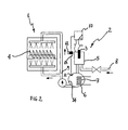
- FIGs 1 and 2 these can be noticed to schematically illustrate a washing machine, such as in particular a clothes washing machine for commercial or professional application ( Figure 1 ) and a dishwashing machine ( Figure 2 ), which is provided with a washing chamber 1, in which items 4 as clothes, dishes, or the like, are placed for washing, and a boiler 6 provided with heating means 7 of a kind suitable for heating up water.
- the boiler 6 is supplied with water delivered from the water supply line via a duct 8 connected thereto.
- the boiler 6 and the washing chamber 1 are fluidly connected with each other via a second supply duct 9, so that the hot water produced by the boiler 6 is capable of being conveyed into the washing chamber 1.
- An electrolytic cell 2 fitting the purposes of the present invention comprises a first electrode 3 consisting of a mass of zinc, or zinc alloy, in a compact form, i.e. not subdivided into a plurality of distinct particles, and located within a container in which the water to be treated is collected prior to being sent to the boiler 6.
- the electrolytic cell 2 further comprises a second electrode 5 in contact with the water to be treated, which is preferably formed by the same walls defining said container.
- the electrodes 3, 5 are energized electrically by a current generator 10.
- the anode 3 is eluted in the water contained in the vessel acting as the catode 5, i.e. in the cell itself, so that the concentration of zinc ions is capable of reaching a pre-determined effective value.
- the water flowing through the electrolytic cell, and duly added with zinc ions (Zn 2+ ) there, is eventually delivered into the boiler 6, where the zinc ions will then slow down scale formation on the wet walls of both the boiler 6 and the heating means 7 to a significant extent.
- M Zn 2 + I * T * M Zn z * F from which there can be derived the value of the current I to be set upon, i.e. applied to the electrolytic cell for a specified mass of zinc M Zn 2+ to be able to be eluted in the water during a total time T of known length.
- the value of the mass of zinc M Zn 2+ may be selected on the basis of the disclosure in the afore-cited scientific article by PP Coetzee et al.
- the washing machine shown in Figures 1 and 2 is provided with sensor means 11 and processing means 12 adapted to determine the (Zn)-to-(Ca) ratio, i.e. the ratio of the concentration by weight of zinc to the concentration by weight of calcium in the water downstream from the electrolytic cell 2 and, in particular, inside the boiler 6.
- Control means 13 are provided in a signal-exchanging communication arrangement with the processing means 12 and the current generator 10 in view of controlling, i.e. adjusting the current being supplied to the electrolytic cell according to the detected value of the (Zn)-to-(Ca) ratio, wherein said ratio will preferably be held at a value greater than 0.06*10 -3 by said control means 13.
- Such control, or adjustment, of the intensity of the current supplied by the current generator 10 to the electrolytic cell 2 may of course be done either on a continuous-duty basis, i.e. in such manner as to ensure that the electrolytic cell 2 will produce zinc ions (Zn 2+ ) to an amount that is substantially proportional to the amount of water flowing through the same cell so that the concentration of zinc in the water is held nearly constant, or in a non-continuous manner.
- the need for such control to be done on a non-continuous basis can for instance become true, i.e.
- the inner surfaces 14 of the boiler 6 be coated with a particular polymeric material. This is made possible by the fact that such surfaces are exposed to temperatures that do not exceed 100°C, or do it by just a few degrees centigrade at most, thereby keeping well below the melting point of the polymeric material used for coating.
- a particular polymeric material is preferably the one that is generally known under the trade-name "RILSAN", produced by the company ARKENSOL, although such polyamide-based plastics commonly referred to by their abbreviations PA6, PA11, PA12, PA46, PA66 may equally be used to such purpose, owing to these polymeric materials being barely sensitive to, i.e. hardly affected by limestone depositing thereon. Through such additional provision, the amount of limestone depositing and scale forming inside the boiler 6 is further reduced to quite considerable an extent.
- FIG. 1 a clothes washing machine of a commercial, i.e. heavy-duty kind is illustrated in Figure 1 , the present invention may be readily applied also to household-type clothes washing machines, in which the boiler 6 and the heating means 7 are largely known to be incorporated in the wash tub, or outer drum, of the machine, while the afore-cited duct 9 is in this case missing.
- the sensor means 11 would be located inside the wash tub and the walls of such tub that are in contact with the washing water might in turn be coated with any of the above-cited polymeric materials.
- the operating principle of the electrolytic cell as a system aimed at reducing scale formation on the inner surfaces of the boiler 6 and the heating means 7 thereof, as well as the ways and modes used to control the intensity of the current supplied to the electrolytic cell 2, can be applied to a multiplicity of machines, in which there is provided a boiler for heating up water or generating steam. Therefore, with reference to the exemplary embodiments shown in Figures 3 through to 7, the same considerations and explanations will apply as the ones set forth above in connection with Figures 1 and 2 as far as the electrolytic cell and the scale-preventing action exerted by such cell are concerned.
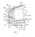
- FIGs 3 and 4 Illustrated in Figures 3 and 4 is a boiling pan of the kind intended for use in professional kitchens.
- such boiling pan of an indirectly heated type i.e. a boiling pan in which the food to be cooked does not come into any contact with the water, since it is contained in a compartment that is separated from the circuit carrying the process water.
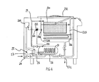
- Shown in Figure 4 is on the other hand a boiling pan of the directly heated type, in which the process water comes in contact with the food to be cooked.
- An example of direct-heating boiling pan for professional foodservice applications to which the present invention can be applied is the so-called pasta-cooker.
- Both types of boiling pans comprise a first water inlet duct 28 fluidly connecting the boiling pan to the water supply line, and a boiler 26 provided with heating means 27 to heat up the water being let thereinto.
- a collecting vessel 215 is provided to accept and hold the cooking water heated up by the heating means 27 in the boiler 26.
- An electrolytic cell 22 is located in the water inlet duct 28 at a site upstream to the boiler 26, so that the water being taken in from the water supply line will flow through the electrolytic cell 22 and be correspondingly enriched by the addition of zinc ions (Zn 2+ ) eluted by a zinc electrode 23 located within a container in which the water to be treated is collected prior to being delivered into the boiler 26.
- the electrolytic cell 22 further comprises a second electrode 25 in contact with the water to be treated and preferably formed by the same walls defining said container.
- the electrolytic cell 22 is energized, i.e. supplied electrically by a current generator 210, which is in a signal-exchanging communication arrangement with control means 213 that are adapted to control and adjust the intensity of the current supplied to the electrolytic cell 22.
- control means 213 receive signals that are indicative of the existing (Zn)-to-(Ca) ratio, i.e. the ratio of the concentration by weight of zinc to the concentration by weight of calcium measured in the water downstream from the electrolytic cell 22 and, in particular, inside the boiler 26 by processing means 212.
- These processing means determine the above-mentioned (Zn)-to-(Ca) ratio on the basis of what is detected by sensor means 211 arranged within the boiler 26.
- the (Zn)-to-(Ca) ratio is preferably held at a value greater than 0.06*10 -3 by said control means 213.
- further heating means 27a may be provided inside the collecting vessel 215 to the purpose of holding the water collecting thereinside at the temperature to which it has been heated up in the boiler 26, and at which it has been delivered by the boiler 26; for this reason, in view of ensuring that limestone will not give rise to scale formation on the heating means 27a, further sensor means 211 a are located inside the collecting vessel 215 in contact with the cooking water.
- the processing means will of course determine a pair of values for the (Zn)-to-(Ca) ratios detected in the two corresponding water containing regions being monitored by the sensor means 211 and 211 a, respectively.
- the control means 213 that receive the signals being delivered by said processing means 212 will control the current generator in such manner as to ensure that the current supplied to the electrolytic cell 22 is enabled to elute zinc ions (Zn 2+ ) to a sufficient amount to cater for both the volume of water contained in the boiler 26 and the volume of water contained in the collecting vessel 215.
- the inner surfaces 214 of the boiler 26 may be provided with a suitable coating of a polyamide-based polymeric material, such as PA6, PA11, PA12, PA46, PA66, as they are generally known in the art, owing to these polymeric materials being barely sensitive to, i.e. hardly affected by limestone depositing thereon.
- a polyamide-based polymeric material such as PA6, PA11, PA12, PA46, PA66
- the boiling pan of the directly heated type ( Figure 4 ) comprises a second duct 29 provided to convey the water heated up by the boiler 26 into the collecting vessel 215.
- a perforated container 230 adapted to accommodate the food to be cooked is mounted in a horizontally pivoted, i.e balancing, arrangement relative to the collecting vessel 215 in such manner as to be able to be let down and be received thereinside.
- drain ducts 231 for letting the water off the boiler 26 and the collecting vessel 215, as well as ensuring a safety overflow provision to let out excess water from the vessel 215.
- a lid 232 is used to close the collecting vessel 215.
- the professional boiling pan of the indirectly heated type shown in Figure 3 is provided with a lid 232 that closes a holding vessel 233, in which the food is placed for cooking.
- This holding vessel 233 does not receive the water heated in the boiler 26 in its interior, but is rather formed within the collecting vessel 215 so that a jacket, or hollow space, is created between the holding vessel 233 and the collecting vessel 215 for the hot water flowing in from the boiler 26 to be able to fill it up.
- the collecting vessel 215 and the food holding vessel 233 are provided with drain ducts 231 for letting off both the water and cooking liquids.
- the collecting vessel 215 is furthermore provided with a vent conduit 234 to vent out vapours forming thereinside.
- the water inlet duct 28 connected to the water supply line includes a branch pipe 235 provided to convey in-flowing water from the water supply line into the food holding vessel 233.
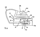
- FIG. 5 and 6 Illustrated in Figures 5 and 6 are two steam irons of the integrated-boiler and the separate-boiler types, respectively. Both types of steam irons comprise a reservoir 340 adapted to receive and hold water being filled in from the water supply line. Via a duct 39, this reservoir 340 is fluidly connected to a boiler 36 provided with water heating means 37 adapted to heat up the water flowing in from said reservoir.
- An electrolytic cell 32 is provided to reduce scale formation inside the boiler 36 through the elution of zinc ions (Zn 2+ ). To this purpose, the electrolytic cell 32 comprises a first zinc electrode 33 and a second electrode 35 in contact with said water and preferably formed by the walls of the same reservoir 340. The electrolytic cell 32 is energized, i.e.
- control means 313 receive signals that are indicative of the existing (Zn)-to-(Ca) ratio, i.e. the ratio of the concentration by weight of zinc to the concentration by weight of calcium measured in the water downstream from the electrolytic cell 32 and, in particular, inside the boiler 36 by processing means 312.
- processing means 312. determine the above-mentioned (Zn)-to-(Ca) ratio on the basis of what is detected by sensor means 311 arranged within the boiler 36.
- the (Zn)-to-(Ca) ratio is preferably held at a value above 0.06*10 -3 by said control means 213.
- the inner surfaces 314 of the boiler 36 may be provided with a suitable coating of a polyamide-based polymeric material, such as PA6, PA11, PA12, PA46, PA66, as they are generally known in the art, owing to these polymeric materials being barely sensitive to, i.e. hardly affected by limestone depositing thereon.
- a polyamide-based polymeric material such as PA6, PA11, PA12, PA46, PA66
- the boiler 36 is provided on the smoothing plate 342 of the same iron, which is capable of being grasped and held by means of a handle 346.
- a selector switch 341 is provided to set and adjust the temperature of the smoothing plate 342, and a plug 343 is provided for connection of the iron to the power supply.
- the water reservoir 340, the boiler 36 and the electrolytic cell 32 are housed in a first unit 344, whereas a second unit 345, which is fluidly connected to the first unit 344, comprises a handle 346 and a smoothing plate 342.
- a first unit 344 the water, as enriched through the addition of zinc ions (Zn 2+ ), is conveyed into the boiler 36, where it is converted into steam.
- Such steam is in turn delivered to the second unit 345 via a duct 347, and made available there for release onto and through the smoothing plate 342.
- a selector switch 341 is provided for setting the particular ironing programme selected for the steam iron to carry out.
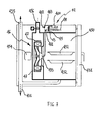
- Illustrated in Figure 7 is a steam cooker, i.e. an oven of the direct-heating type intended for cooking food by steam.
- the oven is provided with a cooking cavity 450, inside which there are removably associated one or more trays or pans 452 provided for the food to be cooked to be placed thereupon.
- the oven is connected to the water supply line via a water inlet duct 48, which supplies water to a diffuser 453 that is rotatably mounted relative to the cooking cavity 450.
- An electric motor 454 drives said diffuser 453 rotatably, so that the water is spread about by centrifugal effect towards heating means 47 arranged around the diffuser 453.
- the water hitting the heating means 47 is in the form of tiny droplets that vaporize instantly.
- the heating means 47 and the water diffuser 453 form substantially a boiler 46.
- An electrolytic cell 42 is located in the water inlet duct 48 at a site upstream to the boiler 46, so that the water being taken in from the water supply line will flow through the electrolytic cell 42 and be correspondingly enriched by the addition of zinc ions (Zn 2+ ) eluted by a zinc electrode 43 located within a container in which the water to be treated is collected prior to being delivered into the boiler 46.
- the electrolytic cell 42 further comprises a second electrode 25 in contact with the water to be treated and preferably formed by the same walls defining said container.
- the electrolytic cell 42 is energized, i.e. supplied electrically by a current generator 410, which is in a signal-exchanging communication arrangement with control means 413 that are adapted to control and adjust the intensity of the current supplied to the electrolytic cell 42.
- control means 413 receive signals that are indicative of the existing (Zn)-to-(Ca) ratio, i.e. the ratio of the concentration by weight of zinc to the concentration by weight of calcium measured in the water downstream from the electrolytic cell 42 by processing means 212.
- These processing means determine the above-mentioned (Zn)-to-(Ca) ratio on the basis of what is detected by sensor means 411 provided downstream from the electrolytic cell 42.
- the (Zn)-to-(Ca) ratio is preferably held at a value greater than 0.06*10 -3 by said control means 413.
- the oven is further provided with a drain conduit 431 for letting cooking liquids and remainders off the cooking cavity 450, as well as conduits 455 and 456 to vent off cooking fumes and vapours and adjust humidity in the cooking cavity, respectively.
- a drain conduit 431 for letting cooking liquids and remainders off the cooking cavity 450, as well as conduits 455 and 456 to vent off cooking fumes and vapours and adjust humidity in the cooking cavity, respectively.
- the present invention can most obviously be applied to any type or kind of food cooking oven that is provided with heating means 47 and spray means 453 adapted to project the water supplied by the duct 48 onto the heating means 47 to cause it to vaporize.
- electrolytic cell particularly advantageous is further the possibility given for the electrolytic cell to be located at such sites in the machine as to allow the related zinc electrode to be readily accessible and conveniently removable in view for replacement.
Landscapes
- Engineering & Computer Science (AREA)
- Chemical & Material Sciences (AREA)
- Environmental & Geological Engineering (AREA)
- Water Supply & Treatment (AREA)
- Electrochemistry (AREA)
- General Chemical & Material Sciences (AREA)
- Life Sciences & Earth Sciences (AREA)
- Hydrology & Water Resources (AREA)
- Textile Engineering (AREA)
- Chemical Kinetics & Catalysis (AREA)
- Organic Chemistry (AREA)
- Food Science & Technology (AREA)
- Combustion & Propulsion (AREA)
- Mechanical Engineering (AREA)
- General Engineering & Computer Science (AREA)
- Water Treatment By Electricity Or Magnetism (AREA)
Abstract
Description
- The present invention refers to a machine, such as a washing machine, in particular a dishwashing or warewashing machine and a clothes washing machine, an ironing machine, a food cooking oven and a boiling pan of the kind intended for use in professional kitchens, such machine being provided with water heating means and being further provided with a device adapted to curb and reduce scale formation.
- Machines are largely known nowadays, and commonly used in a variety of industrial and commercial applications, which are provided with a water-carrying circuit, in which water supplied from the main water supply line is circulated, and heating means designed to heat up such water, possibly even to values beyond the boiling temperature thereof. Machines of such kind may for instance include household or commercial washing machines, such as clothes washing or dishwashing machines, ironing appliances, along with food cooking ovens and boiling pans intended for use in professional kitchens.
- It is a largely known fact that, in machines of the above-indicated kind, the provision of heating elements submerged in the water being let in from the water supply line in view of heating it up to an appropriate working or process temperature, gives in almost the totality of cases rise to a quite typical problem due to the fact that such elements as calcium bicarbonate dissolved in said water converts into calcium carbonate, generally known also as "limestone", owing to the temperature of the water being heated to high values. Calcium carbonate then deposits on the surface of the heating elements in the form of scale, thereby causing the heat-exchange efficiency, i.e. the heat conductivity of the heating elements to suffer even marked reductions. In addition, such reduced capacity of the heaters of exchanging, i.e. transferring heat to the water that is due to be heated up by them, gives in turn rise to the disadvantageous effect of the same heating elements being exposed to overheating, which implies a real risk for them to eventually incur irreparable damages.
- Removing such surface scale may substantially occur in a couple of manners. A first such manner is based on having the heating elements and the water-carrying circuit, through which the water being heated is circulated, periodically submitted to regular, appropriate maintenance aimed at either mechanically or chemically cleaning them in view of physically removing the scale formed thereon. Generally, while removing scale mechanically from a surface calls for the use of appropriate tools, doing it chemically is based on the use of special substances that are capable of chemically combining with calcium carbonate and dissolving it.
- Anyway, both processes can be readily appreciated to involve extended periods of machine inoperativeness, along with the use of skilled personnel to carry out the required cleaning operations.
- A second manner, in which scale may practically be prevented from forming, is based on having the water cleared of the calcium bicarbonate dissolved therein, i.e. dissolved calcium bicarbonate removed from the water prior to the latter being conveyed into the boiler, i.e. the vessel housing the heating elements provided to heat up said water. Such removal of scale-forming elements from the water can be done with the use of chemical-type water softeners, nanofilters, reverse osmosis cells, or the like.
- Now, the use of devices of the above-cited kind, further to introducing added complexity in the construction of the machine as a whole, requires said devices to be anyway submitted to regular maintenance periodically, in view of ensuring that they are kept adequately effective in removing calcium bicarbonate.
- Known among the above-cited water softening devices there are also galvanic-cell and electrochemical-cell devices, which substantially consist of an electrode couple submerged in the water to be softened. The electrodes release ions or produce salts that enable or cause scale-forming elements to crystallize and/or coagulate, rather than depositing on the walls of the water-carrying circuit in which the same water is circulated. An example of devices of such kind is illustrated in the British
patent application GB 2 384 536 - Known from the European patent application
EP 07118651.4 - The basic object of the present invention is to provide a machine, i.e. a washing machine, such as in particular a clothes washing machine and a dishwashing machine, an ironing machine, a steam cooker of the directly heated kind and a boiling pan of the kind intended for use in professional kitchens, and the like, which does away with the drawbacks and limitations of prior-art machines that make use of water heating means.
- Within this general object, it is a purpose of the present invention to provide a washing machine that enables the amount of water-softening agents that have to be added to the detergents in view of softening the wash or process water to be reduced and/or the use of such agents to be fully eliminated.
- It is a further purpose of the present invention to provide a washing machine, a boiling pan for foodservice applications, an ironing machine and a steam-cooking oven, which ensure improved overall reliability and do not require any particular maintenance to be carried out on the water heating means.
- Yet a further purpose of the present invention is to provide a machine using or incorporating water heating means, in which the water-softening, i.e. scaling prevention capacity may be adjusted in accordance with the actual flow rate of the water being used by the machine, as well as in accordance with the degree of hardness of the water to be treated.
- Another, equally important purpose of the present invention is to provide a machine of the above-cited kind, in which the scale-preventing device and/or any of the component parts thereof can be replaced and/or restored to full operating condition in a most convenient, easy and quick manner.
- According to the present invention, these aims, along with further ones that will become apparent from the following disclosure, are reached in a washing machine, a boiling pan for foodservice applications, an ironing machine and a steam-cooking oven incorporating the features and characteristics as defined and recited in the appended claims.
- Advantages and features of the present invention will anyway be more readily understood from the description that is given below by way of non-limiting example with reference to the accompanying drawings, in which:
-
Figure 1 is a schematical view of a clothes washing machine of the type intended for commercial applications, as provided with an electrolytic cell according to the present invention; -
Figure 2 is a schematical view of a dishwashing machine provided with an electrolytic cell according to the present invention; -
Figure 3 is a schematical view of a boiling pan of the indirectly heated type for use in professional kitchens, as provided with an electrolytic cell according to the present invention; -
Figure 4 is a schematical view of a boiling pan of the directly heated type for use in professional kitchens, as provided with an electrolytic cell according to the present invention; -
Figure 5 is a schematical view of a steam iron of the type featuring an integrated boiler, as provided with an electrolytic cell according to the present invention; -
Figure 6 is a schematical view of a steam iron of the type featuring a separate boiler, as provided with an electrolytic cell according to the present invention; -
Figure 7 is a schematical view of a steam oven of the type intended for cooking food by direct steam, as provided with an electrolytic cell according to the present invention. - With reference to
Figures 1 and2 , these can be noticed to schematically illustrate a washing machine, such as in particular a clothes washing machine for commercial or professional application (Figure 1 ) and a dishwashing machine (Figure 2 ), which is provided with awashing chamber 1, in whichitems 4 as clothes, dishes, or the like, are placed for washing, and a boiler 6 provided with heating means 7 of a kind suitable for heating up water. The boiler 6 is supplied with water delivered from the water supply line via aduct 8 connected thereto. The boiler 6 and thewashing chamber 1 are fluidly connected with each other via a second supply duct 9, so that the hot water produced by the boiler 6 is capable of being conveyed into thewashing chamber 1. The arrows appearing inFigures 1 and2 are situated along the water-carryingcircuit 8, 9 of the washing machine to indicate the flow-path followed by the water from the water supply line up to the point at which it is let into thewashing chamber 1. For reasons of greater representative convenience and simplicity, the part of the water-carrying circuit provided to eventually let the water off the washing chamber has not been illustrated. - The water being let in from the water supply line is caused to flow through an
electrolytic cell 2 provided in theduct 8 upstream to the boiler 6. Anelectrolytic cell 2 fitting the purposes of the present invention comprises a first electrode 3 consisting of a mass of zinc, or zinc alloy, in a compact form, i.e. not subdivided into a plurality of distinct particles, and located within a container in which the water to be treated is collected prior to being sent to the boiler 6. Theelectrolytic cell 2 further comprises a second electrode 5 in contact with the water to be treated, which is preferably formed by the same walls defining said container. The electrodes 3, 5 are energized electrically by acurrent generator 10. - The properties of zinc in reducing production of calcium carbonate in water are largely known as such in the art, as this is for instance set forth in the publication ISSN 0378-4738 Water SA Vol. 24 No. 1, January 1998, by PP Coetzee et al., available at following Internet address: http://www.wrc.org.za/archives/watersa%20archive/1998/January/jan98 p77.pdf.
- Disclosed in the above-cited publication is the scientific demonstration of the fact that the presence of zinc ions in an adequate percentage is effective in slowing down the nucleation rate of calcium carbonate, while modifying the crystalline structure of the limestone, i.e. scale, to thereby weaken its bond with the hot surface on which it deposits, so as to ultimately enhance the removability thereof, i.e. the aptitude thereof to being removed. From the research and investigation results published in the above-cited article there can be derived the values of minimum concentration by weight of zinc in relation to, i.e. versus the concentration of calcium, for which a measurable scale-preventing effect is obtained. In particular, the alteration of the crystalline structure of the scale, i.e. the formation of aragonite rather than calcite, under a resulting weakening of the bond between calcium carbonate and the hot surface on which the latter settles, occurs when the ratio of the concentration by weight of zinc [mg/dm3] to the concentration by weight of calcium [mg/dm3] in the water is greater than 0.06*10-3, i.e. when 0.06 micrograms of zinc [µgZn] for every milligram of calcium [mgCa], wherein by concentrations by weight of zinc and calcium there shall be understood the concentrations by total weight.
- In the washing machine illustrated in
Figures 1 and2 , the anode 3 is eluted in the water contained in the vessel acting as the catode 5, i.e. in the cell itself, so that the concentration of zinc ions is capable of reaching a pre-determined effective value. The water flowing through the electrolytic cell, and duly added with zinc ions (Zn2+) there, is eventually delivered into the boiler 6, where the zinc ions will then slow down scale formation on the wet walls of both the boiler 6 and the heating means 7 to a significant extent. - The concentration of zinc ions eluted in the water can be derived from the mathematical formulation of Faraday's laws:
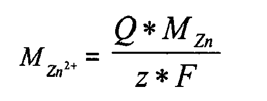
where: - MZn 2+ is the mass of zinc eluted in the water;
- Q is the total charge passed through the water, as calculable by means of the relation:

- MZn is the molar mass of zinc (65.38 g/mol);
- z is the valence number of the zinc ions (Zn2+ ⇒ z = 2);
- F is the Faraday constant (96485.3 C/mol)
- Assuming a constant current I, therefore Q = I*T.
- As a result, the above relation (1) may be rewritten as follows:

from which there can be derived the value of the current I to be set upon, i.e. applied to the electrolytic cell for a specified mass of zinc MZn 2+ to be able to be eluted in the water during a total time T of known length. The value of the mass of zinc MZn 2+ may be selected on the basis of the disclosure in the afore-cited scientific article by PP Coetzee et al. - When the mathematical relations set forth above are considered, it can be most readily appreciated that controlling the current applied to the
electrolytic cell 2 illustrated inFigures 1 and2 will enable a concentration by weight of zinc [µg/dm3] in the water flowing in from the water supply line, which is each time best suited to the actual flow rate and/or degree of hardness of the water to be treated, thereby ensuring that such water will not give rise to scale formation on the inner surfaces of the boiler 6 and the heating means 7 provided thereinside. - To the purpose of adjusting the concentration of zinc eluted in the water, the washing machine shown in
Figures 1 and2 is provided with sensor means 11 and processing means 12 adapted to determine the (Zn)-to-(Ca) ratio, i.e. the ratio of the concentration by weight of zinc to the concentration by weight of calcium in the water downstream from theelectrolytic cell 2 and, in particular, inside the boiler 6.Control means 13 are provided in a signal-exchanging communication arrangement with the processing means 12 and thecurrent generator 10 in view of controlling, i.e. adjusting the current being supplied to the electrolytic cell according to the detected value of the (Zn)-to-(Ca) ratio, wherein said ratio will preferably be held at a value greater than 0.06*10-3 by said control means 13. - Such control, or adjustment, of the intensity of the current supplied by the
current generator 10 to theelectrolytic cell 2 may of course be done either on a continuous-duty basis, i.e. in such manner as to ensure that theelectrolytic cell 2 will produce zinc ions (Zn2+) to an amount that is substantially proportional to the amount of water flowing through the same cell so that the concentration of zinc in the water is held nearly constant, or in a non-continuous manner. The need for such control to be done on a non-continuous basis can for instance become true, i.e. show up during the initial phases of the boiler filling process, when it may in fact be appropriate for the electrolytic cell to be supplied with a current of greater intensity for a certain period of time initially, to then reduce such intensity, and hold it at such reduced value, so as to let the boiler go on operating under regular, steady-state conditions. - In view of enhancing the scale-preventing action ensured by the
electrolytic cell 2, there may be also contemplated that theinner surfaces 14 of the boiler 6 be coated with a particular polymeric material. This is made possible by the fact that such surfaces are exposed to temperatures that do not exceed 100°C, or do it by just a few degrees centigrade at most, thereby keeping well below the melting point of the polymeric material used for coating. Such material is preferably the one that is generally known under the trade-name "RILSAN", produced by the company ARKENSOL, although such polyamide-based plastics commonly referred to by their abbreviations PA6, PA11, PA12, PA46, PA66 may equally be used to such purpose, owing to these polymeric materials being barely sensitive to, i.e. hardly affected by limestone depositing thereon. Through such additional provision, the amount of limestone depositing and scale forming inside the boiler 6 is further reduced to quite considerable an extent. - Although a clothes washing machine of a commercial, i.e. heavy-duty kind is illustrated in
Figure 1 , the present invention may be readily applied also to household-type clothes washing machines, in which the boiler 6 and the heating means 7 are largely known to be incorporated in the wash tub, or outer drum, of the machine, while the afore-cited duct 9 is in this case missing. In this case, the sensor means 11 would be located inside the wash tub and the walls of such tub that are in contact with the washing water might in turn be coated with any of the above-cited polymeric materials. - The operating principle of the electrolytic cell as a system aimed at reducing scale formation on the inner surfaces of the boiler 6 and the heating means 7 thereof, as well as the ways and modes used to control the intensity of the current supplied to the
electrolytic cell 2, can be applied to a multiplicity of machines, in which there is provided a boiler for heating up water or generating steam. Therefore, with reference to the exemplary embodiments shown inFigures 3 through to 7, the same considerations and explanations will apply as the ones set forth above in connection withFigures 1 and2 as far as the electrolytic cell and the scale-preventing action exerted by such cell are concerned. - Illustrated in
Figures 3 and4 is a boiling pan of the kind intended for use in professional kitchens. In particular, shown inFigure 3 is such boiling pan of an indirectly heated type, i.e. a boiling pan in which the food to be cooked does not come into any contact with the water, since it is contained in a compartment that is separated from the circuit carrying the process water. Shown inFigure 4 is on the other hand a boiling pan of the directly heated type, in which the process water comes in contact with the food to be cooked. An example of direct-heating boiling pan for professional foodservice applications to which the present invention can be applied is the so-called pasta-cooker. - Both types of boiling pans comprise a first
water inlet duct 28 fluidly connecting the boiling pan to the water supply line, and aboiler 26 provided with heating means 27 to heat up the water being let thereinto. A collectingvessel 215 is provided to accept and hold the cooking water heated up by the heating means 27 in theboiler 26. Anelectrolytic cell 22 is located in thewater inlet duct 28 at a site upstream to theboiler 26, so that the water being taken in from the water supply line will flow through theelectrolytic cell 22 and be correspondingly enriched by the addition of zinc ions (Zn2+) eluted by azinc electrode 23 located within a container in which the water to be treated is collected prior to being delivered into theboiler 26. Theelectrolytic cell 22 further comprises asecond electrode 25 in contact with the water to be treated and preferably formed by the same walls defining said container. - The
electrolytic cell 22 is energized, i.e. supplied electrically by acurrent generator 210, which is in a signal-exchanging communication arrangement with control means 213 that are adapted to control and adjust the intensity of the current supplied to theelectrolytic cell 22. These control means 213 receive signals that are indicative of the existing (Zn)-to-(Ca) ratio, i.e. the ratio of the concentration by weight of zinc to the concentration by weight of calcium measured in the water downstream from theelectrolytic cell 22 and, in particular, inside theboiler 26 by processing means 212. These processing means determine the above-mentioned (Zn)-to-(Ca) ratio on the basis of what is detected by sensor means 211 arranged within theboiler 26. The (Zn)-to-(Ca) ratio is preferably held at a value greater than 0.06*10-3 by said control means 213. - In the case of a heavy-duty, i.e. professional boiling pan of the direct-heating type (
Figure 4 ), further heating means 27a may be provided inside the collectingvessel 215 to the purpose of holding the water collecting thereinside at the temperature to which it has been heated up in theboiler 26, and at which it has been delivered by theboiler 26; for this reason, in view of ensuring that limestone will not give rise to scale formation on the heating means 27a, further sensor means 211 a are located inside the collectingvessel 215 in contact with the cooking water. In this case, the processing means will of course determine a pair of values for the (Zn)-to-(Ca) ratios detected in the two corresponding water containing regions being monitored by the sensor means 211 and 211 a, respectively. The control means 213 that receive the signals being delivered by said processing means 212 will control the current generator in such manner as to ensure that the current supplied to theelectrolytic cell 22 is enabled to elute zinc ions (Zn2+) to a sufficient amount to cater for both the volume of water contained in theboiler 26 and the volume of water contained in the collectingvessel 215. - As this has already been described hereinbefore with reference to
Figures 1 and2 , theinner surfaces 214 of theboiler 26 may be provided with a suitable coating of a polyamide-based polymeric material, such as PA6, PA11, PA12, PA46, PA66, as they are generally known in the art, owing to these polymeric materials being barely sensitive to, i.e. hardly affected by limestone depositing thereon. - As far as the structure of the professional boiling pans illustrated in
Figures 3 and4 is concerned, the boiling pan of the directly heated type (Figure 4 ) comprises a second duct 29 provided to convey the water heated up by theboiler 26 into the collectingvessel 215. Aperforated container 230 adapted to accommodate the food to be cooked is mounted in a horizontally pivoted, i.e balancing, arrangement relative to the collectingvessel 215 in such manner as to be able to be let down and be received thereinside. There are further provideddrain ducts 231 for letting the water off theboiler 26 and the collectingvessel 215, as well as ensuring a safety overflow provision to let out excess water from thevessel 215. Alid 232 is used to close the collectingvessel 215. - The professional boiling pan of the indirectly heated type shown in
Figure 3 is provided with alid 232 that closes a holdingvessel 233, in which the food is placed for cooking. This holdingvessel 233 does not receive the water heated in theboiler 26 in its interior, but is rather formed within the collectingvessel 215 so that a jacket, or hollow space, is created between the holdingvessel 233 and the collectingvessel 215 for the hot water flowing in from theboiler 26 to be able to fill it up. The collectingvessel 215 and thefood holding vessel 233 are provided withdrain ducts 231 for letting off both the water and cooking liquids. The collectingvessel 215 is furthermore provided with avent conduit 234 to vent out vapours forming thereinside. - The
water inlet duct 28 connected to the water supply line includes abranch pipe 235 provided to convey in-flowing water from the water supply line into thefood holding vessel 233. - Illustrated in
Figures 5 and6 are two steam irons of the integrated-boiler and the separate-boiler types, respectively. Both types of steam irons comprise areservoir 340 adapted to receive and hold water being filled in from the water supply line. Via a duct 39, thisreservoir 340 is fluidly connected to aboiler 36 provided with water heating means 37 adapted to heat up the water flowing in from said reservoir. Anelectrolytic cell 32 is provided to reduce scale formation inside theboiler 36 through the elution of zinc ions (Zn2+). To this purpose, theelectrolytic cell 32 comprises a first zinc electrode 33 and asecond electrode 35 in contact with said water and preferably formed by the walls of thesame reservoir 340. Theelectrolytic cell 32 is energized, i.e. supplied electrically by acurrent generator 310, which is in a signal-exchanging communication arrangement with control means 313 that are adapted to control and adjust the intensity of the current being supplied to theelectrolytic cell 32. These control means 313 receive signals that are indicative of the existing (Zn)-to-(Ca) ratio, i.e. the ratio of the concentration by weight of zinc to the concentration by weight of calcium measured in the water downstream from theelectrolytic cell 32 and, in particular, inside theboiler 36 by processing means 312. These processing means determine the above-mentioned (Zn)-to-(Ca) ratio on the basis of what is detected by sensor means 311 arranged within theboiler 36. The (Zn)-to-(Ca) ratio is preferably held at a value above 0.06*10-3 by said control means 213. - As this has already been described hereinbefore with reference to
Figures 1 to 4 , theinner surfaces 314 of theboiler 36 may be provided with a suitable coating of a polyamide-based polymeric material, such as PA6, PA11, PA12, PA46, PA66, as they are generally known in the art, owing to these polymeric materials being barely sensitive to, i.e. hardly affected by limestone depositing thereon. - In the steam iron embodied as illustrated in
Figure 5 , theboiler 36 is provided on the smoothingplate 342 of the same iron, which is capable of being grasped and held by means of ahandle 346. Aselector switch 341 is provided to set and adjust the temperature of the smoothingplate 342, and aplug 343 is provided for connection of the iron to the power supply. - In the steam iron embodied as illustrated in
Figure 6 , thewater reservoir 340, theboiler 36 and theelectrolytic cell 32 are housed in afirst unit 344, whereas asecond unit 345, which is fluidly connected to thefirst unit 344, comprises ahandle 346 and a smoothingplate 342. Inside thefirst unit 344, the water, as enriched through the addition of zinc ions (Zn2+), is conveyed into theboiler 36, where it is converted into steam. Such steam is in turn delivered to thesecond unit 345 via aduct 347, and made available there for release onto and through the smoothingplate 342. Aselector switch 341 is provided for setting the particular ironing programme selected for the steam iron to carry out. - Illustrated in
Figure 7 is a steam cooker, i.e. an oven of the direct-heating type intended for cooking food by steam. The oven is provided with acooking cavity 450, inside which there are removably associated one or more trays or pans 452 provided for the food to be cooked to be placed thereupon. The oven is connected to the water supply line via awater inlet duct 48, which supplies water to adiffuser 453 that is rotatably mounted relative to thecooking cavity 450. Anelectric motor 454 drives saiddiffuser 453 rotatably, so that the water is spread about by centrifugal effect towards heating means 47 arranged around thediffuser 453. The water hitting the heating means 47 is in the form of tiny droplets that vaporize instantly. The heating means 47 and thewater diffuser 453 form substantially aboiler 46. - An
electrolytic cell 42 is located in thewater inlet duct 48 at a site upstream to theboiler 46, so that the water being taken in from the water supply line will flow through theelectrolytic cell 42 and be correspondingly enriched by the addition of zinc ions (Zn2+) eluted by azinc electrode 43 located within a container in which the water to be treated is collected prior to being delivered into theboiler 46. Theelectrolytic cell 42 further comprises asecond electrode 25 in contact with the water to be treated and preferably formed by the same walls defining said container. - The
electrolytic cell 42 is energized, i.e. supplied electrically by acurrent generator 410, which is in a signal-exchanging communication arrangement with control means 413 that are adapted to control and adjust the intensity of the current supplied to theelectrolytic cell 42. These control means 413 receive signals that are indicative of the existing (Zn)-to-(Ca) ratio, i.e. the ratio of the concentration by weight of zinc to the concentration by weight of calcium measured in the water downstream from theelectrolytic cell 42 by processing means 212. These processing means determine the above-mentioned (Zn)-to-(Ca) ratio on the basis of what is detected by sensor means 411 provided downstream from theelectrolytic cell 42. The (Zn)-to-(Ca) ratio is preferably held at a value greater than 0.06*10-3 by said control means 413. - The oven is further provided with a
drain conduit 431 for letting cooking liquids and remainders off thecooking cavity 450, as well asconduits duct 48 onto the heating means 47 to cause it to vaporize. - Fully apparent from the above description is therefore the ability of the present invention to effectively reach the aims and advantages cited afore by in fact providing a machine equipped with water heating means of improved reliability, in which the scale-preventing effect can be appropriately adjusted based on the actual flow rate or amount of water being used by the machine, as well as based on the degree of hardness of the water to be treated. A machine made in accordance with the present invention enables the average operating life thereof to be markedly extended in time, while at the same time ensuring unaltered performance levels.
- Particularly advantageous is further the possibility given for the electrolytic cell to be located at such sites in the machine as to allow the related zinc electrode to be readily accessible and conveniently removable in view for replacement.
- It shall be appreciated that the materials used in connection with the present invention, as well as the shape and the sizing of the various parts involved, may each time be selected so as to more appropriately meet the particular requirements or suit the particular application.
- It shall further be appreciated that the various elements forming the object of and being part of the present invention shall certainly not be solely embodied in the manners that has been described and illustrated hereinbefore, but can rather be implemented in many other embodiments - although not specifically illustrated here - without departing from the scope of the present invention.
Claims (18)
- Washing machine comprising:- a boiler (6) provided with heating means (7) adapted to heat up water,- at least a first water inlet duct (8) fluidly connecting said boiler (6) to a water supply line,- a washing chamber (1) fluidly connected to said boiler (6),characterized in that said first water inlet duct (8) is provided with an electrolytic cell (2) adapted to be passed therethrough by said water, said cell being further adapted to produce zinc ions (Zn2+) that are eluted and dispersed in said water, and in that sensor means (11) and processing means (12) are provided to determine the ratio (Zn)/(Ca) of the concentration by weight of zinc to the concentration by weight of calcium in said water.
- Washing machine according to claim 1, further comprising control means (13) in signal communication with a current generator (10) which energizes said electrolytic cell (2) for controlling the operation thereof according to a detected value of said (Zn)/(Ca) ratio.
- Washing machine according to claim 2, wherein said (Zn)/(Ca) ratio is held at a value greater than 0.06*10-3 by said control means (13).
- Washing machine according to any of the preceding claims, characterized in that it is a clothes washing machine or a dishwashing machine.
- Boiling pan of the type intended for use in professional kitchens, comprising:- a boiler (26) provided with heating means (27) adapted to heat up water,- at least a first water inlet duct (28) fluidly connecting said boiler (26) to a water supply line,- a collecting vessel (215) for receiving said water,characterized in that said first water inlet duct (28) is provided with an electrolytic cell (22) adapted to be passed therethrough by said water, said cell being further adapted to produce zinc ions (Zn2+) that are eluted and dispersed in said water.
- Boiling pan according to claim 5 comprising sensor means (211, 211 a) and processing means (212) adapted to determine the ratio (Zn)/(Ca) of the concentration by weight of zinc to the concentration by weight of calcium in said water.
- Boiling pan according to claim 6 comprising control means (213) in signal communication with a current generator (210) which energizes said electrolytic cell (2) for controlling the operation thereof according to a detected value of said (Zn)/(Ca) ratio.
- Boiling pan according to claim 7, wherein said (Zn)/(Ca) ratio is held at a value greater than 0.06*10-3 by said control means (213).
- Boiling pan according to any of the claims 6 to 8, wherein said collecting vessel (215) defines a compartment adapted to receive a balancing container (230) for containing food to be cooked.
- Steam iron comprising:- a boiler (36) provided with heating means (37) adapted to heat up water,- a reservoir (340) adapted to contain said water and fluidly connected to said boiler (36),characterized by comprising an electrolytic cell (32) adapted to be passed therethrough by said water, said cell being further adapted to produce zinc ions (Zn2+) that are eluted and dispersed in said water.
- Steam iron according to claim 10 comprising sensor means (311) and processing means (312) adapted to determine the ratio (Zn)/(Ca) of the concentration by weight of zinc to the concentration by weight of calcium in said water.
- Steam iron according to claim 11 comprising control means (313) provided in signal communication with a current generator (310) which energizes said electrolytic cell (32) for controlling the operation thereof according to a detected value of said (Zn)/(Ca) ratio.
- Steam iron according to claim 12, wherein said (Zn)/(Ca) ratio is held at a value greater than 0.06*10-3 by said control means (313).
- Steam iron according to any of the claims 10 to 13, comprising a first unit (344) accommodating the boiler (36), the reservoir (340) and the electrolytic cell (32), and a second unit (345) that is fluidly connected with said first unit (344) and comprises a handle (346) and a smoothing plate (342).
- Food cooking oven comprising:- a cooking cavity (450),- heating means (47) adapted to heat up the cooking cavity (450),- water projecting means (453) fluidly connected to a water supply line via a first water inlet duct (48), said water projecting means (453) being adapted to project water onto the heating means (47),characterized in that said first water inlet duct (48) is provided with an electrolytic cell (42) adapted to be passed therethrough by said water, said cell being further adapted to produce zinc ions (Zn2+) that are eluted and dispersed in said water.
- Food cooking oven according to claim 15, comprising sensor means (411) and processing means (412) adapted to determine the ratio (Zn)/(Ca) of the concentration by weight of zinc to the concentration by weight of calcium in said water.
- Food cooking oven according to claim 16, comprising control means (413) provided in signal communication with a current generator (410) which energizes said electrolytic cell (42) for controlling the operation thereof according to a detected value of said (Zn)/(Ca) ratio.
- Food cooking oven according to claim 17, wherein said (Zn)/(Ca) ratio is held at a value greater than 0.06*10-3 by said control means (413).
Priority Applications (2)
| Application Number | Priority Date | Filing Date | Title |
|---|---|---|---|
| EP08425317.8A EP2116516B1 (en) | 2008-05-09 | 2008-05-09 | Machine with water heating means and anti-scale device |
| US12/434,123 US20090277783A1 (en) | 2008-05-09 | 2009-05-01 | Machine with water heating means and anti-scale device |
Applications Claiming Priority (1)
| Application Number | Priority Date | Filing Date | Title |
|---|---|---|---|
| EP08425317.8A EP2116516B1 (en) | 2008-05-09 | 2008-05-09 | Machine with water heating means and anti-scale device |
Publications (2)
| Publication Number | Publication Date |
|---|---|
| EP2116516A1 true EP2116516A1 (en) | 2009-11-11 |
| EP2116516B1 EP2116516B1 (en) | 2014-03-12 |
Family
ID=39790459
Family Applications (1)
| Application Number | Title | Priority Date | Filing Date |
|---|---|---|---|
| EP08425317.8A Not-in-force EP2116516B1 (en) | 2008-05-09 | 2008-05-09 | Machine with water heating means and anti-scale device |
Country Status (2)
| Country | Link |
|---|---|
| US (1) | US20090277783A1 (en) |
| EP (1) | EP2116516B1 (en) |
Cited By (10)
| Publication number | Priority date | Publication date | Assignee | Title |
|---|---|---|---|---|
| WO2009153265A1 (en) * | 2008-06-20 | 2009-12-23 | BSH Bosch und Siemens Hausgeräte GmbH | Household appliance, particularly dishwasher or washer |
| WO2014031308A3 (en) * | 2012-08-21 | 2014-08-28 | Premark Feg L.L.C. | Warewash machine with descaling/deliming system and method |
| EP2843101A1 (en) * | 2013-08-30 | 2015-03-04 | ELECTROLUX PROFESSIONAL S.p.A. | Washing machine comprising a de-scaling apparatus |
| EP2985264A1 (en) * | 2014-08-13 | 2016-02-17 | Sentinel Performance Solutions Ltd | Electrolytic water treatment for scale prevention |
| EP3425285A1 (en) * | 2017-07-05 | 2019-01-09 | Electrolux Appliances Aktiebolag | Water management system |
| CN109875474A (en) * | 2018-10-24 | 2019-06-14 | 海底捞控股有限公司 | A kind of chaffy dish pot and its cleaning method and cleaning device |
| EP3623706A1 (en) * | 2018-09-11 | 2020-03-18 | Convotherm Elektrogeräte GmbH | Cooking appliance arrangement, especially an industrial cooking appliance arrangement |
| CN113243874A (en) * | 2021-04-28 | 2021-08-13 | 宁波方太厨具有限公司 | Cleaning machine and cleaning method |
| EP3892934A1 (en) | 2020-04-09 | 2021-10-13 | Eccotemp Systems, LLC | Improved water heater device and method of use |
| US11448424B2 (en) | 2020-04-09 | 2022-09-20 | Eccotemp Systems, LLC | Tankless water heater with display and electronic control |
Families Citing this family (2)
| Publication number | Priority date | Publication date | Assignee | Title |
|---|---|---|---|---|
| CN110372110A (en) * | 2019-07-31 | 2019-10-25 | 科淋(北京)科技有限公司 | A kind of efficient scale material and its preparation method and application |
| US11852381B2 (en) | 2020-04-09 | 2023-12-26 | Eccotemp Systems, LLC | Water heater device and method of use |
Citations (5)
| Publication number | Priority date | Publication date | Assignee | Title |
|---|---|---|---|---|
| WO2003091161A1 (en) * | 2002-04-26 | 2003-11-06 | The Coca-Cola Company | Water treatment system and water heater with cathodic protection and method |
| JP2004049946A (en) * | 2002-07-16 | 2004-02-19 | Kosumosu Enterp:Kk | Water cleaning pot and water cleaning method using the same |
| EP1762546A1 (en) * | 2005-09-09 | 2007-03-14 | BSH Bosch und Siemens Hausgeräte GmbH | Process for electrochemical descaling of water in a houshold apparatus |
| DE202007005471U1 (en) * | 2007-04-16 | 2007-06-14 | V-Zug Ag | Method for conditioning the water input for domestic appliances has a separate water inlet unit comprising electrodialysis and electrolytic cells |
| EP1920655A1 (en) * | 2006-11-10 | 2008-05-14 | Electrolux Professional S.P.A. | Improved steaming oven |
Family Cites Families (9)
| Publication number | Priority date | Publication date | Assignee | Title |
|---|---|---|---|---|
| DE3729800A1 (en) * | 1987-09-05 | 1989-03-16 | Krups Stiftung | ELECTRICALLY OPERATED STEAM IRON |
| DE8901904U1 (en) * | 1989-02-17 | 1989-07-20 | Lechmetall Landsberg GmbH, 8910 Landsberg | Steam generator for cooking appliances with decalcification device |
| IT1253692B (en) * | 1991-07-17 | 1995-08-22 | Zanussi Grandi Impianti Spa | STEAM GENERATION DEVICE FOR FOOD COOKING EQUIPMENT, SUCH AS COOKING OVENS OR SIMILAR. |
| IT1267582B1 (en) * | 1994-09-09 | 1997-02-07 | Zanussi Grandi Impianti Spa | OVEN EQUIPPED WITH AN IMPROVED HUMIDITY MEASUREMENT DEVICE |
| US20030213503A1 (en) * | 2002-05-17 | 2003-11-20 | The Procter & Gamble Company | Signal-based electrochemical methods for automatic dishwashing |
| US20030213505A1 (en) * | 2002-05-17 | 2003-11-20 | Price Kenneth Nathan | Energy-efficient automatic dishwashing appliances |
| US6746609B2 (en) * | 2002-08-21 | 2004-06-08 | Berile B. Stander | Cooling tower water treatment |
| GB2429124B (en) * | 2005-08-11 | 2010-10-20 | Otter Controls Ltd | Scale detection on water heating elements |
| US7638031B2 (en) * | 2005-12-16 | 2009-12-29 | Elgressy Engineering Services Ltd. | Depressing precipitation of sparingly soluble salts in a water supply |
-
2008
- 2008-05-09 EP EP08425317.8A patent/EP2116516B1/en not_active Not-in-force
-
2009
- 2009-05-01 US US12/434,123 patent/US20090277783A1/en not_active Abandoned
Patent Citations (5)
| Publication number | Priority date | Publication date | Assignee | Title |
|---|---|---|---|---|
| WO2003091161A1 (en) * | 2002-04-26 | 2003-11-06 | The Coca-Cola Company | Water treatment system and water heater with cathodic protection and method |
| JP2004049946A (en) * | 2002-07-16 | 2004-02-19 | Kosumosu Enterp:Kk | Water cleaning pot and water cleaning method using the same |
| EP1762546A1 (en) * | 2005-09-09 | 2007-03-14 | BSH Bosch und Siemens Hausgeräte GmbH | Process for electrochemical descaling of water in a houshold apparatus |
| EP1920655A1 (en) * | 2006-11-10 | 2008-05-14 | Electrolux Professional S.P.A. | Improved steaming oven |
| DE202007005471U1 (en) * | 2007-04-16 | 2007-06-14 | V-Zug Ag | Method for conditioning the water input for domestic appliances has a separate water inlet unit comprising electrodialysis and electrolytic cells |
Non-Patent Citations (1)
| Title |
|---|
| COETZEE P P ET AL: "Scale reduction and scale modification effects induced by Zn and other metal species in physical water treatment", WATER SA, PRETORIA, SA, vol. 24, no. 1, 1 January 1998 (1998-01-01), pages 77 - 84, XP002466508, ISSN: 0378-4738 * |
Cited By (15)
| Publication number | Priority date | Publication date | Assignee | Title |
|---|---|---|---|---|
| WO2009153265A1 (en) * | 2008-06-20 | 2009-12-23 | BSH Bosch und Siemens Hausgeräte GmbH | Household appliance, particularly dishwasher or washer |
| CN104661576B (en) * | 2012-08-21 | 2017-03-22 | 浦瑞玛柯Feg有限责任公司 | Dishwasher with descaling/calcification system and method |
| WO2014031308A3 (en) * | 2012-08-21 | 2014-08-28 | Premark Feg L.L.C. | Warewash machine with descaling/deliming system and method |
| CN104661576A (en) * | 2012-08-21 | 2015-05-27 | 浦瑞玛柯Feg有限责任公司 | Dishwasher with descaling/calcification system and method |
| EP2843101A1 (en) * | 2013-08-30 | 2015-03-04 | ELECTROLUX PROFESSIONAL S.p.A. | Washing machine comprising a de-scaling apparatus |
| GB2531635B (en) * | 2014-08-13 | 2018-11-14 | Sentinel Performance Solutions Ltd | Water treatment |
| EP2985264A1 (en) * | 2014-08-13 | 2016-02-17 | Sentinel Performance Solutions Ltd | Electrolytic water treatment for scale prevention |
| EP3425285A1 (en) * | 2017-07-05 | 2019-01-09 | Electrolux Appliances Aktiebolag | Water management system |
| WO2019007648A1 (en) * | 2017-07-05 | 2019-01-10 | Electrolux Appliances Aktiebolag | Water management system |
| EP3623706A1 (en) * | 2018-09-11 | 2020-03-18 | Convotherm Elektrogeräte GmbH | Cooking appliance arrangement, especially an industrial cooking appliance arrangement |
| CN109875474A (en) * | 2018-10-24 | 2019-06-14 | 海底捞控股有限公司 | A kind of chaffy dish pot and its cleaning method and cleaning device |
| EP3892934A1 (en) | 2020-04-09 | 2021-10-13 | Eccotemp Systems, LLC | Improved water heater device and method of use |
| EP3892935A1 (en) | 2020-04-09 | 2021-10-13 | Eccotemp Systems, LLC | Improved water heater device and method of use |
| US11448424B2 (en) | 2020-04-09 | 2022-09-20 | Eccotemp Systems, LLC | Tankless water heater with display and electronic control |
| CN113243874A (en) * | 2021-04-28 | 2021-08-13 | 宁波方太厨具有限公司 | Cleaning machine and cleaning method |
Also Published As
| Publication number | Publication date |
|---|---|
| EP2116516B1 (en) | 2014-03-12 |
| US20090277783A1 (en) | 2009-11-12 |
Similar Documents
| Publication | Publication Date | Title |
|---|---|---|
| EP2116516B1 (en) | Machine with water heating means and anti-scale device | |
| JP4617386B2 (en) | Steam cooker | |
| EP2031114B1 (en) | Method for detecting abnormality in a fabric treatment appliance having a steam generator | |
| EP2813613B1 (en) | Method and apparatus for detecting impurity deposits in flow-through water heaters | |
| JP3747156B2 (en) | Equipment for electronic monitoring of lime deposits | |
| EP0744150B1 (en) | Dishwashing machine with electric heating means | |
| US20100192310A1 (en) | Method for controlling the generation of suds in a washing machine and a washing machine suitable therefor | |
| EP2843101B1 (en) | Washing machine comprising a de-scaling apparatus | |
| CN105849334B (en) | Washing machine and method for controlling washing machine | |
| AU2003277648A1 (en) | Ion eluting unit and device loaded with same | |
| CA2638918A1 (en) | Method for operating a steam generator in a fabric treatment appliance | |
| NZ589937A (en) | Water conducting household appliance which heats washing liquid in a reservoir particularly a dishwasher or washing machine | |
| CN105849332B (en) | Washing machine and the method for controlling washing machine | |
| WO2007004785A1 (en) | Control method for time display in drum type washer by spray steam | |
| JP2012500376A (en) | Apparatus and method for rapid heating of liquid | |
| EP2657392B1 (en) | Method for washing laundry in a laundry washing machine and laundry washing machine | |
| US8025740B2 (en) | Process for conducting cleaning operations in a fluid-receiving device of a foodstuff-processing apparatus, and fluid-receiving device and foodstuff-processing apparatus therefor | |
| EP2031113A1 (en) | Method for operating a steam generator in a fabric treatment appliance | |
| CN106574420A (en) | Household appliance comprising a recirculating pump system | |
| EP2254453B1 (en) | Dishwasher and method for cleaning wash ware | |
| EP2031117B1 (en) | Fabric treatment appliance with steam backflow device | |
| EA014995B1 (en) | Method for washing laundry in a program-controlled domestic appliance, and corresponding domestic appliance | |
| CN111733580B (en) | Household appliances that produce steam | |
| CN109805741A (en) | Boiler type steam heater, food cooking machine and scale-deposit-preventing processing method | |
| CN114424892B (en) | Scale detection method for steam cooking equipment and steam cooking equipment |
Legal Events
| Date | Code | Title | Description |
|---|---|---|---|
| PUAI | Public reference made under article 153(3) epc to a published international application that has entered the european phase |
Free format text: ORIGINAL CODE: 0009012 |
|
| AK | Designated contracting states |
Kind code of ref document: A1 Designated state(s): AT BE BG CH CY CZ DE DK EE ES FI FR GB GR HR HU IE IS IT LI LT LU LV MC MT NL NO PL PT RO SE SI SK TR |
|
| AX | Request for extension of the european patent |
Extension state: AL BA MK RS |
|
| 17P | Request for examination filed |
Effective date: 20100430 |
|
| 17Q | First examination report despatched |
Effective date: 20100601 |
|
| AKX | Designation fees paid |
Designated state(s): AT BE BG CH CY CZ DE DK EE ES FI FR GB GR HR HU IE IS IT LI LT LU LV MC MT NL NO PL PT RO SE SI SK TR |
|
| GRAP | Despatch of communication of intention to grant a patent |
Free format text: ORIGINAL CODE: EPIDOSNIGR1 |
|
| INTG | Intention to grant announced |
Effective date: 20130926 |
|
| GRAS | Grant fee paid |
Free format text: ORIGINAL CODE: EPIDOSNIGR3 |
|
| GRAA | (expected) grant |
Free format text: ORIGINAL CODE: 0009210 |
|
| AK | Designated contracting states |
Kind code of ref document: B1 Designated state(s): AT BE BG CH CY CZ DE DK EE ES FI FR GB GR HR HU IE IS IT LI LT LU LV MC MT NL NO PL PT RO SE SI SK TR |
|
| REG | Reference to a national code |
Ref country code: GB Ref legal event code: FG4D |
|
| REG | Reference to a national code |
Ref country code: CH Ref legal event code: EP |
|
| REG | Reference to a national code |
Ref country code: AT Ref legal event code: REF Ref document number: 656178 Country of ref document: AT Kind code of ref document: T Effective date: 20140315 |
|
| REG | Reference to a national code |
Ref country code: IE Ref legal event code: FG4D |
|
| REG | Reference to a national code |
Ref country code: DE Ref legal event code: R096 Ref document number: 602008030777 Country of ref document: DE Effective date: 20140424 |
|
| REG | Reference to a national code |
Ref country code: SE Ref legal event code: TRGR |
|
| REG | Reference to a national code |
Ref country code: NL Ref legal event code: VDEP Effective date: 20140312 |
|
| PG25 | Lapsed in a contracting state [announced via postgrant information from national office to epo] |
Ref country code: NO Free format text: LAPSE BECAUSE OF FAILURE TO SUBMIT A TRANSLATION OF THE DESCRIPTION OR TO PAY THE FEE WITHIN THE PRESCRIBED TIME-LIMIT Effective date: 20140612 Ref country code: LT Free format text: LAPSE BECAUSE OF FAILURE TO SUBMIT A TRANSLATION OF THE DESCRIPTION OR TO PAY THE FEE WITHIN THE PRESCRIBED TIME-LIMIT Effective date: 20140312 |
|
| REG | Reference to a national code |
Ref country code: AT Ref legal event code: MK05 Ref document number: 656178 Country of ref document: AT Kind code of ref document: T Effective date: 20140312 |
|
| REG | Reference to a national code |
Ref country code: LT Ref legal event code: MG4D |
|
| PG25 | Lapsed in a contracting state [announced via postgrant information from national office to epo] |
Ref country code: CY Free format text: LAPSE BECAUSE OF FAILURE TO SUBMIT A TRANSLATION OF THE DESCRIPTION OR TO PAY THE FEE WITHIN THE PRESCRIBED TIME-LIMIT Effective date: 20140312 Ref country code: FI Free format text: LAPSE BECAUSE OF FAILURE TO SUBMIT A TRANSLATION OF THE DESCRIPTION OR TO PAY THE FEE WITHIN THE PRESCRIBED TIME-LIMIT Effective date: 20140312 |
|
| PG25 | Lapsed in a contracting state [announced via postgrant information from national office to epo] |
Ref country code: LV Free format text: LAPSE BECAUSE OF FAILURE TO SUBMIT A TRANSLATION OF THE DESCRIPTION OR TO PAY THE FEE WITHIN THE PRESCRIBED TIME-LIMIT Effective date: 20140312 Ref country code: HR Free format text: LAPSE BECAUSE OF FAILURE TO SUBMIT A TRANSLATION OF THE DESCRIPTION OR TO PAY THE FEE WITHIN THE PRESCRIBED TIME-LIMIT Effective date: 20140312 |
|
| PG25 | Lapsed in a contracting state [announced via postgrant information from national office to epo] |
Ref country code: BG Free format text: LAPSE BECAUSE OF FAILURE TO SUBMIT A TRANSLATION OF THE DESCRIPTION OR TO PAY THE FEE WITHIN THE PRESCRIBED TIME-LIMIT Effective date: 20140612 Ref country code: NL Free format text: LAPSE BECAUSE OF FAILURE TO SUBMIT A TRANSLATION OF THE DESCRIPTION OR TO PAY THE FEE WITHIN THE PRESCRIBED TIME-LIMIT Effective date: 20140312 Ref country code: BE Free format text: LAPSE BECAUSE OF FAILURE TO SUBMIT A TRANSLATION OF THE DESCRIPTION OR TO PAY THE FEE WITHIN THE PRESCRIBED TIME-LIMIT Effective date: 20140312 Ref country code: EE Free format text: LAPSE BECAUSE OF FAILURE TO SUBMIT A TRANSLATION OF THE DESCRIPTION OR TO PAY THE FEE WITHIN THE PRESCRIBED TIME-LIMIT Effective date: 20140312 Ref country code: IS Free format text: LAPSE BECAUSE OF FAILURE TO SUBMIT A TRANSLATION OF THE DESCRIPTION OR TO PAY THE FEE WITHIN THE PRESCRIBED TIME-LIMIT Effective date: 20140712 Ref country code: CZ Free format text: LAPSE BECAUSE OF FAILURE TO SUBMIT A TRANSLATION OF THE DESCRIPTION OR TO PAY THE FEE WITHIN THE PRESCRIBED TIME-LIMIT Effective date: 20140312 Ref country code: RO Free format text: LAPSE BECAUSE OF FAILURE TO SUBMIT A TRANSLATION OF THE DESCRIPTION OR TO PAY THE FEE WITHIN THE PRESCRIBED TIME-LIMIT Effective date: 20140312 |
|
| PG25 | Lapsed in a contracting state [announced via postgrant information from national office to epo] |
Ref country code: SK Free format text: LAPSE BECAUSE OF FAILURE TO SUBMIT A TRANSLATION OF THE DESCRIPTION OR TO PAY THE FEE WITHIN THE PRESCRIBED TIME-LIMIT Effective date: 20140312 Ref country code: AT Free format text: LAPSE BECAUSE OF FAILURE TO SUBMIT A TRANSLATION OF THE DESCRIPTION OR TO PAY THE FEE WITHIN THE PRESCRIBED TIME-LIMIT Effective date: 20140312 Ref country code: ES Free format text: LAPSE BECAUSE OF FAILURE TO SUBMIT A TRANSLATION OF THE DESCRIPTION OR TO PAY THE FEE WITHIN THE PRESCRIBED TIME-LIMIT Effective date: 20140312 Ref country code: PL Free format text: LAPSE BECAUSE OF FAILURE TO SUBMIT A TRANSLATION OF THE DESCRIPTION OR TO PAY THE FEE WITHIN THE PRESCRIBED TIME-LIMIT Effective date: 20140312 |
|
| REG | Reference to a national code |
Ref country code: DE Ref legal event code: R097 Ref document number: 602008030777 Country of ref document: DE |
|
| PG25 | Lapsed in a contracting state [announced via postgrant information from national office to epo] |
Ref country code: PT Free format text: LAPSE BECAUSE OF FAILURE TO SUBMIT A TRANSLATION OF THE DESCRIPTION OR TO PAY THE FEE WITHIN THE PRESCRIBED TIME-LIMIT Effective date: 20140714 Ref country code: LU Free format text: LAPSE BECAUSE OF FAILURE TO SUBMIT A TRANSLATION OF THE DESCRIPTION OR TO PAY THE FEE WITHIN THE PRESCRIBED TIME-LIMIT Effective date: 20140509 |
|
| REG | Reference to a national code |
Ref country code: CH Ref legal event code: PL |
|
| PLBE | No opposition filed within time limit |
Free format text: ORIGINAL CODE: 0009261 |
|
| STAA | Information on the status of an ep patent application or granted ep patent |
Free format text: STATUS: NO OPPOSITION FILED WITHIN TIME LIMIT |
|
| PG25 | Lapsed in a contracting state [announced via postgrant information from national office to epo] |
Ref country code: CH Free format text: LAPSE BECAUSE OF NON-PAYMENT OF DUE FEES Effective date: 20140531 Ref country code: DK Free format text: LAPSE BECAUSE OF FAILURE TO SUBMIT A TRANSLATION OF THE DESCRIPTION OR TO PAY THE FEE WITHIN THE PRESCRIBED TIME-LIMIT Effective date: 20140312 Ref country code: MC Free format text: LAPSE BECAUSE OF FAILURE TO SUBMIT A TRANSLATION OF THE DESCRIPTION OR TO PAY THE FEE WITHIN THE PRESCRIBED TIME-LIMIT Effective date: 20140312 Ref country code: LI Free format text: LAPSE BECAUSE OF NON-PAYMENT OF DUE FEES Effective date: 20140531 |
|
| 26N | No opposition filed |
Effective date: 20141215 |
|
| GBPC | Gb: european patent ceased through non-payment of renewal fee |
Effective date: 20140612 |
|
| REG | Reference to a national code |
Ref country code: IE Ref legal event code: MM4A |
|
| REG | Reference to a national code |
Ref country code: FR Ref legal event code: ST Effective date: 20150130 |
|
| REG | Reference to a national code |
Ref country code: DE Ref legal event code: R097 Ref document number: 602008030777 Country of ref document: DE Effective date: 20141215 |
|
| PG25 | Lapsed in a contracting state [announced via postgrant information from national office to epo] |
Ref country code: IE Free format text: LAPSE BECAUSE OF NON-PAYMENT OF DUE FEES Effective date: 20140509 |
|
| PG25 | Lapsed in a contracting state [announced via postgrant information from national office to epo] |
Ref country code: GB Free format text: LAPSE BECAUSE OF NON-PAYMENT OF DUE FEES Effective date: 20140612 Ref country code: FR Free format text: LAPSE BECAUSE OF NON-PAYMENT OF DUE FEES Effective date: 20140602 |
|
| PG25 | Lapsed in a contracting state [announced via postgrant information from national office to epo] |
Ref country code: SI Free format text: LAPSE BECAUSE OF FAILURE TO SUBMIT A TRANSLATION OF THE DESCRIPTION OR TO PAY THE FEE WITHIN THE PRESCRIBED TIME-LIMIT Effective date: 20140312 |
|
| PG25 | Lapsed in a contracting state [announced via postgrant information from national office to epo] |
Ref country code: MT Free format text: LAPSE BECAUSE OF FAILURE TO SUBMIT A TRANSLATION OF THE DESCRIPTION OR TO PAY THE FEE WITHIN THE PRESCRIBED TIME-LIMIT Effective date: 20140312 |
|
| PG25 | Lapsed in a contracting state [announced via postgrant information from national office to epo] |
Ref country code: GR Free format text: LAPSE BECAUSE OF FAILURE TO SUBMIT A TRANSLATION OF THE DESCRIPTION OR TO PAY THE FEE WITHIN THE PRESCRIBED TIME-LIMIT Effective date: 20140613 |
|
| PG25 | Lapsed in a contracting state [announced via postgrant information from national office to epo] |
Ref country code: TR Free format text: LAPSE BECAUSE OF FAILURE TO SUBMIT A TRANSLATION OF THE DESCRIPTION OR TO PAY THE FEE WITHIN THE PRESCRIBED TIME-LIMIT Effective date: 20140312 Ref country code: HU Free format text: LAPSE BECAUSE OF FAILURE TO SUBMIT A TRANSLATION OF THE DESCRIPTION OR TO PAY THE FEE WITHIN THE PRESCRIBED TIME-LIMIT; INVALID AB INITIO Effective date: 20080509 |
|
| PGFP | Annual fee paid to national office [announced via postgrant information from national office to epo] |
Ref country code: DE Payment date: 20160520 Year of fee payment: 9 |
|
| PGFP | Annual fee paid to national office [announced via postgrant information from national office to epo] |
Ref country code: IT Payment date: 20160524 Year of fee payment: 9 Ref country code: SE Payment date: 20160519 Year of fee payment: 9 |
|
| REG | Reference to a national code |
Ref country code: DE Ref legal event code: R119 Ref document number: 602008030777 Country of ref document: DE |
|
| REG | Reference to a national code |
Ref country code: SE Ref legal event code: EUG |
|
| PG25 | Lapsed in a contracting state [announced via postgrant information from national office to epo] |
Ref country code: SE Free format text: LAPSE BECAUSE OF NON-PAYMENT OF DUE FEES Effective date: 20170510 |
|
| PG25 | Lapsed in a contracting state [announced via postgrant information from national office to epo] |
Ref country code: DE Free format text: LAPSE BECAUSE OF NON-PAYMENT OF DUE FEES Effective date: 20171201 |
|
| PG25 | Lapsed in a contracting state [announced via postgrant information from national office to epo] |
Ref country code: IT Free format text: LAPSE BECAUSE OF NON-PAYMENT OF DUE FEES Effective date: 20170509 |