EP2116401A1 - Torsion beam type suspension - Google Patents
Torsion beam type suspension Download PDFInfo
- Publication number
- EP2116401A1 EP2116401A1 EP08711603A EP08711603A EP2116401A1 EP 2116401 A1 EP2116401 A1 EP 2116401A1 EP 08711603 A EP08711603 A EP 08711603A EP 08711603 A EP08711603 A EP 08711603A EP 2116401 A1 EP2116401 A1 EP 2116401A1
- Authority
- EP
- European Patent Office
- Prior art keywords
- torsion beam
- arm
- arms
- attachments
- wheel
- Prior art date
- Legal status (The legal status is an assumption and is not a legal conclusion. Google has not performed a legal analysis and makes no representation as to the accuracy of the status listed.)
- Granted
Links
Images




Classifications
-
- B—PERFORMING OPERATIONS; TRANSPORTING
- B60—VEHICLES IN GENERAL
- B60G—VEHICLE SUSPENSION ARRANGEMENTS
- B60G21/00—Interconnection systems for two or more resiliently-suspended wheels, e.g. for stabilising a vehicle body with respect to acceleration, deceleration or centrifugal forces
- B60G21/02—Interconnection systems for two or more resiliently-suspended wheels, e.g. for stabilising a vehicle body with respect to acceleration, deceleration or centrifugal forces permanently interconnected
- B60G21/04—Interconnection systems for two or more resiliently-suspended wheels, e.g. for stabilising a vehicle body with respect to acceleration, deceleration or centrifugal forces permanently interconnected mechanically
- B60G21/05—Interconnection systems for two or more resiliently-suspended wheels, e.g. for stabilising a vehicle body with respect to acceleration, deceleration or centrifugal forces permanently interconnected mechanically between wheels on the same axle but on different sides of the vehicle, i.e. the left and right wheel suspensions being interconnected
- B60G21/051—Trailing arm twist beam axles
-
- B—PERFORMING OPERATIONS; TRANSPORTING
- B60—VEHICLES IN GENERAL
- B60B—VEHICLE WHEELS; CASTORS; AXLES FOR WHEELS OR CASTORS; INCREASING WHEEL ADHESION
- B60B35/00—Axle units; Parts thereof ; Arrangements for lubrication of axles
- B60B35/02—Dead axles, i.e. not transmitting torque
- B60B35/08—Dead axles, i.e. not transmitting torque of closed hollow section
-
- B—PERFORMING OPERATIONS; TRANSPORTING
- B60—VEHICLES IN GENERAL
- B60G—VEHICLE SUSPENSION ARRANGEMENTS
- B60G7/00—Pivoted suspension arms; Accessories thereof
- B60G7/008—Attaching arms to unsprung part of vehicle
-
- B—PERFORMING OPERATIONS; TRANSPORTING
- B60—VEHICLES IN GENERAL
- B60G—VEHICLE SUSPENSION ARRANGEMENTS
- B60G2200/00—Indexing codes relating to suspension types
- B60G2200/20—Semi-rigid axle suspensions
- B60G2200/21—Trailing arms connected by a torsional beam, i.e. twist-beam axles
-
- B—PERFORMING OPERATIONS; TRANSPORTING
- B60—VEHICLES IN GENERAL
- B60G—VEHICLE SUSPENSION ARRANGEMENTS
- B60G2200/00—Indexing codes relating to suspension types
- B60G2200/20—Semi-rigid axle suspensions
- B60G2200/23—Trailing arms connected by a U-shaped torsion bar
-
- B—PERFORMING OPERATIONS; TRANSPORTING
- B60—VEHICLES IN GENERAL
- B60G—VEHICLE SUSPENSION ARRANGEMENTS
- B60G2200/00—Indexing codes relating to suspension types
- B60G2200/40—Indexing codes relating to the wheels in the suspensions
- B60G2200/422—Driving wheels or live axles
-
- B—PERFORMING OPERATIONS; TRANSPORTING
- B60—VEHICLES IN GENERAL
- B60G—VEHICLE SUSPENSION ARRANGEMENTS
- B60G2200/00—Indexing codes relating to suspension types
- B60G2200/40—Indexing codes relating to the wheels in the suspensions
- B60G2200/446—Non-steerable wheels
-
- B—PERFORMING OPERATIONS; TRANSPORTING
- B60—VEHICLES IN GENERAL
- B60G—VEHICLE SUSPENSION ARRANGEMENTS
- B60G2202/00—Indexing codes relating to the type of spring, damper or actuator
- B60G2202/10—Type of spring
- B60G2202/13—Torsion spring
- B60G2202/136—Twist-beam type arrangement
-
- B—PERFORMING OPERATIONS; TRANSPORTING
- B60—VEHICLES IN GENERAL
- B60G—VEHICLE SUSPENSION ARRANGEMENTS
- B60G2204/00—Indexing codes related to suspensions per se or to auxiliary parts
- B60G2204/10—Mounting of suspension elements
- B60G2204/12—Mounting of springs or dampers
- B60G2204/124—Mounting of coil springs
- B60G2204/1246—Mounting of coil springs on twist beam axles
-
- B—PERFORMING OPERATIONS; TRANSPORTING
- B60—VEHICLES IN GENERAL
- B60G—VEHICLE SUSPENSION ARRANGEMENTS
- B60G2204/00—Indexing codes related to suspensions per se or to auxiliary parts
- B60G2204/40—Auxiliary suspension parts; Adjustment of suspensions
- B60G2204/43—Fittings, brackets or knuckles
-
- B—PERFORMING OPERATIONS; TRANSPORTING
- B60—VEHICLES IN GENERAL
- B60G—VEHICLE SUSPENSION ARRANGEMENTS
- B60G2204/00—Indexing codes related to suspensions per se or to auxiliary parts
- B60G2204/40—Auxiliary suspension parts; Adjustment of suspensions
- B60G2204/43—Fittings, brackets or knuckles
- B60G2204/4307—Bracket or knuckle for torsional springs
-
- B—PERFORMING OPERATIONS; TRANSPORTING
- B60—VEHICLES IN GENERAL
- B60G—VEHICLE SUSPENSION ARRANGEMENTS
- B60G2206/00—Indexing codes related to the manufacturing of suspensions: constructional features, the materials used, procedures or tools
- B60G2206/01—Constructional features of suspension elements, e.g. arms, dampers, springs
- B60G2206/012—Hollow or tubular elements
-
- B—PERFORMING OPERATIONS; TRANSPORTING
- B60—VEHICLES IN GENERAL
- B60G—VEHICLE SUSPENSION ARRANGEMENTS
- B60G2206/00—Indexing codes related to the manufacturing of suspensions: constructional features, the materials used, procedures or tools
- B60G2206/01—Constructional features of suspension elements, e.g. arms, dampers, springs
- B60G2206/20—Constructional features of semi-rigid axles, e.g. twist beam type axles
-
- B—PERFORMING OPERATIONS; TRANSPORTING
- B60—VEHICLES IN GENERAL
- B60G—VEHICLE SUSPENSION ARRANGEMENTS
- B60G2206/00—Indexing codes related to the manufacturing of suspensions: constructional features, the materials used, procedures or tools
- B60G2206/01—Constructional features of suspension elements, e.g. arms, dampers, springs
- B60G2206/50—Constructional features of wheel supports or knuckles, e.g. steering knuckles, spindle attachments
-
- B—PERFORMING OPERATIONS; TRANSPORTING
- B60—VEHICLES IN GENERAL
- B60G—VEHICLE SUSPENSION ARRANGEMENTS
- B60G2206/00—Indexing codes related to the manufacturing of suspensions: constructional features, the materials used, procedures or tools
- B60G2206/01—Constructional features of suspension elements, e.g. arms, dampers, springs
- B60G2206/70—Materials used in suspensions
- B60G2206/72—Steel
-
- B—PERFORMING OPERATIONS; TRANSPORTING
- B60—VEHICLES IN GENERAL
- B60G—VEHICLE SUSPENSION ARRANGEMENTS
- B60G2206/00—Indexing codes related to the manufacturing of suspensions: constructional features, the materials used, procedures or tools
- B60G2206/01—Constructional features of suspension elements, e.g. arms, dampers, springs
- B60G2206/80—Manufacturing procedures
- B60G2206/81—Shaping
- B60G2206/8103—Shaping by folding or bending
-
- B—PERFORMING OPERATIONS; TRANSPORTING
- B60—VEHICLES IN GENERAL
- B60G—VEHICLE SUSPENSION ARRANGEMENTS
- B60G2206/00—Indexing codes related to the manufacturing of suspensions: constructional features, the materials used, procedures or tools
- B60G2206/01—Constructional features of suspension elements, e.g. arms, dampers, springs
- B60G2206/80—Manufacturing procedures
- B60G2206/82—Joining
- B60G2206/8201—Joining by welding
Definitions
- the present invention relates to a torsion beam suspension, in detail, the construction of attachments to the wheels set to the both ends of the torsion beam extended to the vehicle width direction.
- the conventional torsion beam suspension is composed of a torsion beam and attachments to a body, disclosed JP-U-7-71883 and JP-A-62-299402 .
- the torsion beam is constructed as a single pipe, which includes a cross portion and an arm, and the cross portion is extended in the vehicle width direction and the arm is extended from the both end of the cross portion to the longitudinal direction of the vehicle intermediary of a curving portion.
- the attachments are respectively fixed to the curving portion.
- Attachments to the wheels are set in the opposite end of the curving portion of the arm, intermediary of an axis.
- a tube bush portions are set in the opposite end of the curving portion of the attachments, the bush portions are rotatably attached to the axis member of the vehicle body.
- a torsion beam 60 includes an arm 62 and attachments 63, the arm 63 is formed by bending the ends of a straight pipe 61 to the nearly right-angle direction, the each attachment 63 is set to the end of the arm 62, and an axis 64 is set to the attachment 63.
- An attachment 68 is attached to a curving portion 67 between the pipe 61 and the arm part 62.
- a torsion beam 70 includes a straight pipe 71 and attachments 72, the attachments 72 are attached to the both ends of the straight pipe 71 and the each attachment 72 is formed directing to the longitudinal direction of the vehicle and thus configures an arm 73.
- An axis 74 is set to the arm 73.
- the dimension between the axis 64 and the center 69a of a bush-part 69 provided in the end of the attachment 68 is exactly set as the specified dimension, however, the accuracy of bending the pipe 61 reflects that of setting the axis 64, so that the bending is required with high accuracy.
- the ends of the pipe 71 should be formed trapezoid or ellipse in section, or should be trimmed for forming the wrap-part 75 for the attachments 72 so that manufacturing cost of the pipe 71 becomes higher.
- the trimming causes the remainder of the pipe 71, thereby causing the low yield rate.
- the torsion beam suspension shown in Fig. 9 requires high accuracy with setting of the attachments 72 and the wrap-part 75, because the burn through or the strength reduction of weld is caused if the clearance exists between the wrap-part 75 and the attachments 72.
- the purpose of the invention is to provide a new torsion beam suspension, in which the manufacturing cost reduction and providing the good quality manufacture are achieved, in the light of the above problems.
- a torsion beam suspension of the first aspect of the present invention includes a torsion beam having arms formed by bending both ends of a pipe and wheel attachments inserted to the each arms, in which a portion of the wheel attachment is inserted to an open end of the arm and wheel attachments are welded to the arms.
- the arm can be shortened by the length of the wheel attachment.
- the pipe can be shortened, which is more expensive than a steel plate, so that the material cost can be reduced.
- the position of the arm can be adjusted.
- the manufacture accuracy of the torsion beam can be higher.
- the weld is carried out between the inner peripheral of the open end of the arm and the outer peripheral of the portion of the wheel attachment.
- the weld is carried out in the wrap-part formed between the portion and the arm, so that the problems are prevented such as the burn through or poor strength.
- the weld quality as well as the product quality of torsion beam suspension can be improved.
- the open end of the arm is closed by the wheel attachment.
- the inner of the arm can be prevented from rusting by the wheel attachment, without the rust resisting or the other member. Thus, the cost of them is cut.
- the wheel attachment includes a carrier plate for fixing a wheel carrier, wherein the carrier plate has a hole penetrated thereto in the vehicle width direction; and a carrier bracket including a first portion inserted to the each open end of the arms and a second portion fixed to the carrier plate, wherein an open portion is formed in the second portion and the open portion and the hole construct a shaft-penetrated portion.
- the rear-wheel drive vehicle can be achieved.
- the first portion has an edge, and a diameter of the edge is the smallest in that of the first portion.
- the working performance can be improved, when the portion is inserted to the open portion of the arm.
- a torsion beam 1 includes an arm 11R and a wheel attachment 12R, the arm is formed by bending the end of a pipe 10, the attachment has a portion 22a inserted to the open end 11a of the arm 11R.
- the pipe 10 is bent such that the arm 11R is directed to the rear of the vehicle on the state where the torsion beam 1 is set to the vehicle.
- the upper side shows the front of the vehicle
- the lower side shows the rear of the vehicle
- the arm 11R is bent rearward and in rear of the axis 10a of the pipe 10.
- the open end 11a of the arm 11R is disposed in front of an axle 26R. Due to the above structure, the arm 11R can be shortened.
- the right side of the vehicle is shown in Fig. 1
- the above-mentioned structure is applied to the both side of the vehicle as shown in Fig. 2 .
- the torsion beam 1 includes body attachments 15R and 15L for the vehicle body welded to curved portions 14R and 14L, respectively, which are made by bending the pipe 10, and bush portions 16R and 16L set at the each end of the attachments 15R and 15L pivoted to the axis-part (not shown) of the vehicle. Due to the above structure, the torsion beam 1 is attached to the vehicle rotatably.
- the open end 11a of the arm 11R is not manufactured against the end of the pipe 14, namely the open end 11a is not deformed and is same one before the pipe 10 is bent, so that the manufacturing cost is reduced.
- the attachment 12R includes a carrier plate 21 for fixing a wheel carrier (not shown) and a carrier bracket 22.
- the attachment 12R supports a spring seat 41 and a portion of an absorber bracket 42.
- the carrier plate 21 has a hole 23 penetrated thereto in the vehicle width direction W
- the vehicle width direction W goes through the carrier plate 21.
- the component of the carrier plate 21 is limited particularly.
- the centers of the hole 23 and the wheel carrier may be the same position, so that the carrier plate 21 can be small and light.
- the other parts of the torsion beam suspension are designed more freely.
- the carrier bracket 22 includes an inserted portion 22a and a fixing portion 22b, the portion 22a is inserted to the open end 11a, and the portion 22b extends toward outside of the vehicle width direction from the portion 22a and has the end fixed to the carrier plate 21.
- the portion 22b is disposed as the carrier plate 21 directing to the vehicle width direction W.
- the portion 22a is a tube with external diameter d1.
- the diameter d1 is slightly smaller than the internal diameter of the open end 11a, so that the portion 22a is inserted into the open end 11a slidably. Due to the above structure, the attachment 12R can slide in the axis direction Y of the arm 11R. Furthermore, the attachment 12R is inserted to the open end 11a of the arm 11R from the rear of the vehicle, so that the open end 11a is disposed in front of the axle 26R in the longitudinal direction of the vehicle (see Fig. 1 ).
- the edge 22f of the portion 22a inserted to the open end 11a is formed by the diameter f1.
- the diameter f1 is smaller than the diameter d1.
- the edge 22f has the corner R, so that the diameter of the edge 22f is smaller than the diameter d1.
- the portion 22a is formed tapered, so that the diameter of the edge 22f is smaller than the diameter d1.
- the clearance exists between the interior of the open end 11a and the diameter of the end 22f
- the portion 22a can be inserted to the arm 11R smoothly.
- the working performance can be improved when the portion 22a is inserted to the open end 11a.
- the portion 22a covers the open end 11 a.
- the carrier bracket 22 is pipe and includes the portion 22a and a cap 27, the cap is fixed to the portion 22a, so that the open end 11a is covered with the portion 22a. Due to the above structure, the inner of the arm 11R can be prevented from rusting, by inserting the attachment 15R to the arm 11R.
- the open portion 22c is formed in the portion 22b of the carrier bracket 22.
- the open portion 22c and the penetrate hole 23 construct a shaft-penetrated portion 24.
- the open portion 22c is formed in the rear side of the vehicle. Especially in the portion 22b, the open portion 22c is not formed in the side that the portion 22a is disposed, so that the portion 22a of the carrier bracket keeps rigidity.
- the shaft-penetrated portion 24 is formed in the carrier plate 21 and carrier bracket 22 (the portion 22b).
- the rear-wheel drive vehicle can be achieved in which a drive shaft 25 is penetrated to the shaft-penetrated portion 24.
- the carrier bracket provided with the shaft-penetrated portion 24 is applied to either the front-wheel drive vehicle or four-wheel drive vehicle.
- the carrier bracket can be shared, so that easy management and cost reduction is achieved.
- the size of the penetrate hole 23 and the open portion 22c may be designed considering the diameter of the drive shaft 25, the way to attach the drive shaft, and the rigidity of the each component.
- the arms 11R, 11L are formed by bending both ends of the pipe 10, and the attachments 12R, 12L are inserted to the each open end 11a.
- the attachments 12R and 12L can move in the pipe axis direction Y (see Fig. 4 ).
- the structure in which the attachments 12R and 12L are inserted to the arms 11L and 11R is achieved easily.
- the attachments 15R and 15L are arranged against the curved portions 14R and 14L, and the positions of the attachments 12R, 12L, 15R and 15L with respect to the pipe 10 are adjusted.
- the attachments 12R and 12L are set to the fixing jig (not shown), and also the attachments 15R and 15L are set to the fixing jig (not shown).
- the dimensions DR, DL between the axles 26R, 26L fixed to the attachments 12R, 12L and the centers 17R 17L of the bush portions 16R, 16L are set in the specified dimensions.
- the attachments 12R and 12L are moved independently, so that the dimensions DR and DL are adjusted independently and the specified dimensions are set easily.
- the portion 22a of the carrier bracket 22 may have a step 22d as a stop which can fit to the open end 11a, so that the position of the arm 11R can be fixed.
- the attachment 12R is set to the fixing jig, the alignment of the inclining of the axle 26R (the toe angle and the camber angle) is set positively.
- the attachment 12R can be moved against the arm 11R, and the clearance exists between the arm 11R and the attachment 12R, which can be used as the alignment margin, so that the problems are prevented such as the heavy load put in the each component and bend of the each component, setting the alignment.
- the arm 11R can be moved, so that the adjustment can be more freely, such as the setting of the axles 26R and 26L in the specified dimensions (the adjustment of the DR and DL) and the setting of the alignment (the toe angle, the camber angle), thereby the allowance can be enlarged, with the manufacture accuracy of each component involving the curving of the torsion beam 1.
- the portion 22a is inserted to the open end 11a of the arm 11R, so that the wrap Z is existed between the portion 22a and the arm 11R.
- the clearance can be prevented from existing between the portion 22a and the arm 11R, so that the weld can be prevented from the burn through or the poor strength.
- the weld quality as well as the product quality of torsion beam suspension can be improved.
- the attachments 12 is inserted to the arm 11R, so that the wrap Z is formed definitely, and the deep fillet welding can be carried out, thereby the poor weld can be prevented, involving the burn through and ensuring the reliability of weld strength.
- the torsion beam suspension includes the torsion beam 1 having the arms 11R and 11L formed by bending both ends of the pipe 10 and the wheel attachments 12R and 12L inserted to the arms 11R and 11L, respectively, in which the inserted portions 22a of the attachments 12R and 12L are inserted to open ends 11a of the arms 11R and 11L, and the attachments 12R and 12L are welded to the arms 11R and 11L.
- the arms 11R, 11L can be shortened by length of the wheel attachments 12R, 12L.
- the pipe 10 can be shortened, which is more expensive than a steel plate, so that the material cost can be reduced.
- the arms 11R, 11L are not required for edge forming, so that the cost of forming can be reduced.
- the positions of the arms 11R, 11L can be adjusted.
- the manufacture accuracy of the torsion beam can be higher.
- the arms 11R, 11L can be moved against the open ends 11a, the adjustment with moving of the arms 11R, 11L achieves setting of the axles 26R, 26L in the specified dimensions (the adjustments of the DR, DL) and setting of the alignment (the toe angle and the camber angle).
- torsion beam 1 is shared and applied to the various vehicle involving the body easily.
- the weld is carried out between the inner peripheral of the open end 11a and the outer peripheral of the portion22a.
- the weld is carried out in the wrap Z between the portion 22a, 22a and the arm 11R, 11L, so that the problems are prevented such as the burn through or poor strength.
- the weld quality as well as the product quality of torsion beam suspension can be improved.
- the fillet welding is carried out, the deep fillet welding can be carried out, so that the poor weld can be prevented, involving the burn through and ensuring the reliability of weld strength.
- the open end 11a is closed by the wheel attachment 12R (the cap 27).
- the inner of the arm 11R can be prevented from rusting by wheel attachment, without the rust resisting or preparing the other member. Thus, the cost of them is cut.
- the attachment 12R includes the carrier plate 21 for fixing a wheel carrier (not shown), in which the carrier plate 21 has the hole 26 penetrated thereto in the vehicle width direction W, and the carrier bracket 22 including the inserted portion 22a inserted to the each open end 11a of the arms 11R and the fixing portion 22b fixed to the carrier plate 21.
- the open portion 11a is formed in the portion 22b and the open portion 11a and the hole 23 construct the shaft-penetrated portion 24.
- the rear-wheel drive vehicle can be achieved.
- the carrier bracket provided with the shaft-penetrated portion 24 is applied to either the front-wheel drive vehicle or four-wheel drive vehicle.
- the carrier bracket can be shared, so that easy management and cost reduction is achieved.
- the edge 22f of the portion 22a inserted to the open end 11a is formed by the diameter f1.
- the diameter f1 is smaller than the diameter d1 of the portion 22a.
- the working performance can be improved when the portion is inserted to the open portion of the arm.
- the present invention is applicable in the industrial instrument as the torsion beam suspension.
Landscapes
- Engineering & Computer Science (AREA)
- Mechanical Engineering (AREA)
- Vehicle Body Suspensions (AREA)
Abstract
Description
- The present invention relates to a torsion beam suspension, in detail, the construction of attachments to the wheels set to the both ends of the torsion beam extended to the vehicle width direction.
- Conventionally, some prior arts disclose some torsion beam suspensions, there is known various technology referring to the torsion beam suspension (for example, see
JP-U-7-71883 JP-A-62-299402 - The conventional torsion beam suspension is composed of a torsion beam and attachments to a body, disclosed
JP-U-7-71883 JP-A-62-299402 - Attachments to the wheels are set in the opposite end of the curving portion of the arm, intermediary of an axis. On the other hand, a tube bush portions are set in the opposite end of the curving portion of the attachments, the bush portions are rotatably attached to the axis member of the vehicle body.
- The construction of the conventional torsion beam suspension will be described with reference to the drawings. As shown in
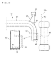
Fig. 8 , atorsion beam 60 includes anarm 62 andattachments 63, thearm 63 is formed by bending the ends of astraight pipe 61 to the nearly right-angle direction, the eachattachment 63 is set to the end of thearm 62, and anaxis 64 is set to theattachment 63. Anattachment 68 is attached to a curvingportion 67 between thepipe 61 and thearm part 62. - The other embodiment of the conventional torsion beam suspension will be described. As shown in
Fig. 9 , atorsion beam 70 includes astraight pipe 71 andattachments 72, theattachments 72 are attached to the both ends of thestraight pipe 71 and the eachattachment 72 is formed directing to the longitudinal direction of the vehicle and thus configures anarm 73. Anaxis 74 is set to thearm 73. - In the torsion beam suspension shown in
Fig. 8 , it is necessary that thearm 62 should be reached to theaxis 64 with bending thepipe 61, so that thelong pipe 61 is required, which is more expensive than a steel plate, thereby requiring the high material cost. - Further in the torsion beam suspension shown in
Fig. 8 , it is also necessary that the ends of thearm 62 should be closed by acap 65 with thewelding 66, as shown inFig. 8 , because the inner of the pipe goes rusty from the open ends if thearm part 62 has the open ends. Such construction unfortunately causes the high cost in manufacturing and attaching of the cap. - As to the torsion beam suspension shown in
Fig. 8 , it is required that the dimension between theaxis 64 and the center 69a of a bush-part 69 provided in the end of theattachment 68 is exactly set as the specified dimension, however, the accuracy of bending thepipe 61 reflects that of setting theaxis 64, so that the bending is required with high accuracy. - In the light of the strength of the torsion beam suspension shown in
Fig. 9 , the ends of thepipe 71 should be formed trapezoid or ellipse in section, or should be trimmed for forming the wrap-part 75 for theattachments 72 so that manufacturing cost of thepipe 71 becomes higher. The trimming causes the remainder of thepipe 71, thereby causing the low yield rate. - The torsion beam suspension shown in
Fig. 9 requires high accuracy with setting of theattachments 72 and the wrap-part 75, because the burn through or the strength reduction of weld is caused if the clearance exists between the wrap-part 75 and theattachments 72. - The purpose of the invention is to provide a new torsion beam suspension, in which the manufacturing cost reduction and providing the good quality manufacture are achieved, in the light of the above problems.
- A torsion beam suspension of the first aspect of the present invention, includes a torsion beam having arms formed by bending both ends of a pipe and wheel attachments inserted to the each arms, in which a portion of the wheel attachment is inserted to an open end of the arm and wheel attachments are welded to the arms.
- Due to the above structure, the arm can be shortened by the length of the wheel attachment. Thus, the pipe can be shortened, which is more expensive than a steel plate, so that the material cost can be reduced. Furthermore, in the step before welding, the position of the arm can be adjusted. Thus, the manufacture accuracy of the torsion beam can be higher.
- Preferably, in the torsion beam suspension of the present invention, the weld is carried out between the inner peripheral of the open end of the arm and the outer peripheral of the portion of the wheel attachment.
- Due to the above structure, the weld is carried out in the wrap-part formed between the portion and the arm, so that the problems are prevented such as the burn through or poor strength. Thus, the weld quality as well as the product quality of torsion beam suspension can be improved.
- Preferably, in the torsion beam suspension of the present invention, the open end of the arm is closed by the wheel attachment.
- Due to the above structure, the inner of the arm can be prevented from rusting by the wheel attachment, without the rust resisting or the other member. Thus, the cost of them is cut.
- Preferably, in the torsion beam suspension of the present invention, the wheel attachment includes a carrier plate for fixing a wheel carrier, wherein the carrier plate has a hole penetrated thereto in the vehicle width direction; and a carrier bracket including a first portion inserted to the each open end of the arms and a second portion fixed to the carrier plate, wherein an open portion is formed in the second portion and the open portion and the hole construct a shaft-penetrated portion.
- Due to the above structure, the rear-wheel drive vehicle can be achieved.
- Preferably, in the torsion beam suspension of the present invention, the first portion has an edge, and a diameter of the edge is the smallest in that of the first portion.
- Due to the above structure, the working performance can be improved, when the portion is inserted to the open portion of the arm.
-
-
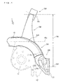
Fig. 1 is a view showing a torsion beam and a wheel attachment. -
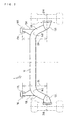
Fig. 2 is a view showing a whole of the torsion beam to which the attachments attached. -
Fig. 3 is a view showing a detail of the attachment. -
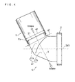
Fig. 4 is a view showing the attachment inserted to an arm. -
Fig. 5 (a) is a view showing the edge of the portion formed with a corner R,Fig. 5 (b) is a view showing the alternative edge of the portion formed tapered. -
Fig. 6 is a view showing the attachment formed with a step. -
Fig. 7 is a view showing the position of the arm welded to the attachment. -
Fig. 8 is a view showing a conventional torsion beam. -
Fig. 9 is a view showing the other conventional torsion beam. - As shown in
Fig. 1 , a torsion beam 1 includes anarm 11R and awheel attachment 12R, the arm is formed by bending the end of apipe 10, the attachment has aportion 22a inserted to theopen end 11a of thearm 11R. - As shown in
Fig. 1 , thepipe 10 is bent such that thearm 11R is directed to the rear of the vehicle on the state where the torsion beam 1 is set to the vehicle. InFig. 1 , the upper side shows the front of the vehicle, and the lower side shows the rear of the vehicle, and thearm 11R is bent rearward and in rear of theaxis 10a of thepipe 10. Theopen end 11a of thearm 11R is disposed in front of anaxle 26R. Due to the above structure, thearm 11R can be shortened. - The right side of the vehicle is shown in
Fig. 1 , the above-mentioned structure is applied to the both side of the vehicle as shown inFig. 2 . The torsion beam 1 includesbody attachments portions pipe 10, andbush portions attachments - As shown in
Fig. 1 , theopen end 11a of thearm 11R is not manufactured against the end of the pipe 14, namely theopen end 11a is not deformed and is same one before thepipe 10 is bent, so that the manufacturing cost is reduced. - As shown in
Figs. 1 and3 , theattachment 12R includes acarrier plate 21 for fixing a wheel carrier (not shown) and acarrier bracket 22. Theattachment 12R supports aspring seat 41 and a portion of anabsorber bracket 42. - As shown in
Fig. 3 , thecarrier plate 21 has ahole 23 penetrated thereto in the vehicle width direction W The vehicle width direction W goes through thecarrier plate 21. It should be noted that the component of thecarrier plate 21 is limited particularly. The centers of thehole 23 and the wheel carrier may be the same position, so that thecarrier plate 21 can be small and light. Thus, the other parts of the torsion beam suspension are designed more freely. - As shown in
Figs. 1 and3 , thecarrier bracket 22 includes an insertedportion 22a and a fixingportion 22b, theportion 22a is inserted to theopen end 11a, and theportion 22b extends toward outside of the vehicle width direction from theportion 22a and has the end fixed to thecarrier plate 21. Theportion 22b is disposed as thecarrier plate 21 directing to the vehicle width direction W. - As shown in
Fig. 4 , theportion 22a is a tube with external diameter d1. The diameter d1 is slightly smaller than the internal diameter of theopen end 11a, so that theportion 22a is inserted into theopen end 11a slidably. Due to the above structure, theattachment 12R can slide in the axis direction Y of thearm 11R. Furthermore, theattachment 12R is inserted to theopen end 11a of thearm 11R from the rear of the vehicle, so that theopen end 11a is disposed in front of theaxle 26R in the longitudinal direction of the vehicle (seeFig. 1 ). - As shown in
Fig. 5(a) , theedge 22f of theportion 22a inserted to theopen end 11a is formed by the diameter f1. The diameter f1 is smaller than the diameter d1. - As shown in
Fig. 5(a) , theedge 22f has the corner R, so that the diameter of theedge 22f is smaller than the diameter d1. Alternatively, in the structure shown inFig. 5(b) , theportion 22a is formed tapered, so that the diameter of theedge 22f is smaller than the diameter d1. - Due to the above structure, the clearance exists between the interior of the
open end 11a and the diameter of theend 22f Thus, theportion 22a can be inserted to thearm 11R smoothly. As a result, the working performance can be improved when theportion 22a is inserted to theopen end 11a. - As shown in
Fig. 4 , theportion 22a covers theopen end 11 a. Thecarrier bracket 22 is pipe and includes theportion 22a and acap 27, the cap is fixed to theportion 22a, so that theopen end 11a is covered with theportion 22a. Due to the above structure, the inner of thearm 11R can be prevented from rusting, by inserting theattachment 15R to thearm 11R. - As shown in
Fig. 3 , theopen portion 22c is formed in theportion 22b of thecarrier bracket 22. Theopen portion 22c and the penetratehole 23 construct a shaft-penetratedportion 24. Theopen portion 22c is formed in the rear side of the vehicle. Especially in theportion 22b, theopen portion 22c is not formed in the side that theportion 22a is disposed, so that theportion 22a of the carrier bracket keeps rigidity. - As shown in
Fig. 3 , the shaft-penetratedportion 24 is formed in thecarrier plate 21 and carrier bracket 22 (theportion 22b). The rear-wheel drive vehicle can be achieved in which adrive shaft 25 is penetrated to the shaft-penetratedportion 24. For example, the carrier bracket provided with the shaft-penetratedportion 24 is applied to either the front-wheel drive vehicle or four-wheel drive vehicle. Thus, the carrier bracket can be shared, so that easy management and cost reduction is achieved. The size of the penetratehole 23 and theopen portion 22c may be designed considering the diameter of thedrive shaft 25, the way to attach the drive shaft, and the rigidity of the each component. - The assembly of the torsion beam 1 will be described.
- As shown in
Fig. 2 , thearms pipe 10, and theattachments open end 11a. In this situation, theattachments Fig. 4 ). According to the above structure inFig 5(a) or 5(b) , the structure in which theattachments arms - As shown in
Fig. 2 , theattachments curved portions attachments pipe 10 are adjusted. In this adjustment, theattachments attachments axles attachments centers 17Rbush portions - The
attachments Fig. 6 , theportion 22a of thecarrier bracket 22 may have astep 22d as a stop which can fit to theopen end 11a, so that the position of thearm 11R can be fixed. - As shown in
Fig. 1 , if theattachment 12R is set to the fixing jig, the alignment of the inclining of theaxle 26R (the toe angle and the camber angle) is set positively. As shown inFig. 4 , theattachment 12R can be moved against thearm 11R, and the clearance exists between thearm 11R and theattachment 12R, which can be used as the alignment margin, so that the problems are prevented such as the heavy load put in the each component and bend of the each component, setting the alignment. - As shown in
Fig.4 and observed above structure, thearm 11R can be moved, so that the adjustment can be more freely, such as the setting of theaxles - As shown in
Fig. 2 and observed above structure, in the state that theattachments attachments pipe 10, they are welded to thepipe 10. - As shown in
Fig. 7 , in the weld M (the all-around weld) between theattachment 15R and thearm 11R, theportion 22a is inserted to theopen end 11a of thearm 11R, so that the wrap Z is existed between theportion 22a and thearm 11R. Thus, the clearance can be prevented from existing between theportion 22a and thearm 11R, so that the weld can be prevented from the burn through or the poor strength. Moreover, the weld quality as well as the product quality of torsion beam suspension can be improved. - As shown in
Fig. 7 , two loads act when theattachment 12 is moved to the pipe axis direction Y of thearm 11R (the load S) and when theattachment 12 is rotated to the pipe axis direction Y (the load R), and the both loads S and R act to the shear direction via the weld M between theportion 22a and thearm 11R. In the welding, the allowable load of the shear load is larger than that of the tensile load, so that reliability of the weld strength can be ensured in the structure assuming that the loads S and R act. In other word, theattachments 12 is inserted to thearm 11R, so that the wrap Z is formed definitely, and the deep fillet welding can be carried out, thereby the poor weld can be prevented, involving the burn through and ensuring the reliability of weld strength. - The embodiment of the present invention is described as the above construction.
- As shown in
Figs. 1 ,2 and4 , the torsion beam suspension includes the torsion beam 1 having thearms pipe 10 and thewheel attachments arms portions 22a of theattachments ends 11a of thearms attachments arms - Due to the above structure, the
arms wheel attachments pipe 10 can be shortened, which is more expensive than a steel plate, so that the material cost can be reduced. - The
arms - In the step before welding, the positions of the
arms - In the step before welding, the
arms arms axles - According to the design for the
wheel attachments - As shown in
Fig. 7 , the weld is carried out between the inner peripheral of theopen end 11a and the outer peripheral of the portion22a. - Due to the above structure, the weld is carried out in the wrap Z between the
portion arm - The fillet welding is carried out, the deep fillet welding can be carried out, so that the poor weld can be prevented, involving the burn through and ensuring the reliability of weld strength.
- As shown in
Fig. 4 , theopen end 11a is closed by thewheel attachment 12R (the cap 27). - Due to the above structure, the inner of the
arm 11R can be prevented from rusting by wheel attachment, without the rust resisting or preparing the other member. Thus, the cost of them is cut. - As shown in
Figs. 1 and4 , theattachment 12R includes thecarrier plate 21 for fixing a wheel carrier (not shown), in which thecarrier plate 21 has the hole 26 penetrated thereto in the vehicle width direction W, and thecarrier bracket 22 including the insertedportion 22a inserted to the eachopen end 11a of thearms 11R and the fixingportion 22b fixed to thecarrier plate 21. In this structure, theopen portion 11a is formed in theportion 22b and theopen portion 11a and thehole 23 construct the shaft-penetratedportion 24. - Due to the above structure, the rear-wheel drive vehicle can be achieved. For example, the carrier bracket provided with the shaft-penetrated
portion 24 is applied to either the front-wheel drive vehicle or four-wheel drive vehicle. Thus, the carrier bracket can be shared, so that easy management and cost reduction is achieved. - As shown in
Fig. 5(a) , in theportion 22a of thecarrier bracket 22, theedge 22f of theportion 22a inserted to theopen end 11a is formed by the diameter f1. The diameter f1 is smaller than the diameter d1 of theportion 22a. - Due to the above structure, the working performance can be improved when the portion is inserted to the open portion of the arm.
- The present invention is applicable in the industrial instrument as the torsion beam suspension.
Claims (5)
- A torsion beam suspension comprising:a torsion beam having arms formed by bending both ends of a pipe; andwheel attachments attached to the each arms,wherein a portion of the wheel attachment is inserted to an open end of the arm andwherein the wheel attachments are welded to the arms.
- The torsion beam suspension as set forth in claim 1,
wherein the weld is carried out between the inner peripheral of the open end of the arm and the outer peripheral of the portion of the wheel attachment. - The torsion beam suspension as set forth in claim 1 or 2,
wherein the open end of the arm is closed by the wheel attachment. - The torsion beam suspension as set forth in any claim 1 to 3,
wherein the wheel attachment comprising:
a carrier plate for fixing a wheel carrier, wherein the carrier plate has a hole penetrated thereto in a vehicle width direction; and
a carrier bracket, including a first portion inserted to the each open end of the arms and a second portion fixed to the carrier plate, wherein an open portion is formed in the second portion and the open portion and the hole construct a shaft-penetrated portion. - The torsion beam suspension as set forth in any claim 1 to 4,
wherein the first portion has an edge, and a diameter of the edge is the smallest in that of the first portion.
Applications Claiming Priority (2)
| Application Number | Priority Date | Filing Date | Title |
|---|---|---|---|
| JP2007051956A JP4301307B2 (en) | 2007-03-01 | 2007-03-01 | Torsion beam suspension |
| PCT/JP2008/052792 WO2008108166A1 (en) | 2007-03-01 | 2008-02-13 | Torsion beam type suspension |
Publications (3)
| Publication Number | Publication Date |
|---|---|
| EP2116401A1 true EP2116401A1 (en) | 2009-11-11 |
| EP2116401A4 EP2116401A4 (en) | 2011-11-30 |
| EP2116401B1 EP2116401B1 (en) | 2013-03-27 |
Family
ID=39738063
Family Applications (1)
| Application Number | Title | Priority Date | Filing Date |
|---|---|---|---|
| EP08711603A Not-in-force EP2116401B1 (en) | 2007-03-01 | 2008-02-13 | Torsion beam type suspension |
Country Status (6)
| Country | Link |
|---|---|
| US (1) | US7959175B2 (en) |
| EP (1) | EP2116401B1 (en) |
| JP (1) | JP4301307B2 (en) |
| CN (2) | CN101626910A (en) |
| RU (1) | RU2394695C1 (en) |
| WO (1) | WO2008108166A1 (en) |
Cited By (4)
| Publication number | Priority date | Publication date | Assignee | Title |
|---|---|---|---|---|
| EP2221196A1 (en) * | 2009-02-24 | 2010-08-25 | Benteler Automobiltechnik GmbH | Twist beam axle and method for its production |
| EP2305492A1 (en) | 2009-10-02 | 2011-04-06 | Benteler Automobiltechnik GmbH | Twist beam axle |
| DE102010012486A1 (en) * | 2010-03-24 | 2011-09-29 | GM Global Technology Operations LLC , (n. d. Ges. d. Staates Delaware) | Suspension of a vehicle and method for producing a cross member thereof |
| WO2011117511A1 (en) * | 2010-03-25 | 2011-09-29 | Peugeot Citroën Automobiles SA | Rear axle assembly for a motor vehicle, comprising a power plant |
Families Citing this family (17)
| Publication number | Priority date | Publication date | Assignee | Title |
|---|---|---|---|---|
| JP5111121B2 (en) * | 2008-01-10 | 2012-12-26 | 本田技研工業株式会社 | Suspension structure |
| CA2644464C (en) * | 2008-10-17 | 2010-04-20 | Arcelormittal Tubular Products Canada Inc. | Twist-axle of variable wall thickness |
| JP2011131700A (en) * | 2009-12-24 | 2011-07-07 | Toyota Motor Corp | Torsion beam type suspension device |
| DE202011103222U1 (en) * | 2011-07-08 | 2012-10-11 | Al-Ko Kober Ag | axis |
| DE102013210142A1 (en) * | 2013-05-31 | 2014-12-04 | Saf-Holland Gmbh | handlebar unit |
| JP6136943B2 (en) * | 2014-01-22 | 2017-05-31 | トヨタ自動車株式会社 | Vehicle suspension |
| JP5879415B1 (en) * | 2014-10-03 | 2016-03-08 | 株式会社エフテック | End plate for suspension members |
| SE540561C2 (en) * | 2015-05-13 | 2018-10-02 | Ningbo Geely Automobile Res & Development Co Ltd | Wheel carrier |
| CN107650609B (en) * | 2016-07-26 | 2020-04-14 | 上海汽车集团股份有限公司 | Torsion beams, suspensions and automobiles |
| DE202016105743U1 (en) | 2016-10-04 | 2016-10-26 | Ford Global Technologies, Llc | Rear suspension for a vehicle |
| DE102016219138B4 (en) | 2016-10-04 | 2026-01-15 | Ford Global Technologies, Llc | Rear axle suspension for a vehicle |
| DE102016219140A1 (en) | 2016-10-04 | 2018-04-05 | Ford Global Technologies, Llc | Rear suspension for a vehicle |
| JP6849510B2 (en) * | 2017-04-04 | 2021-03-24 | 株式会社エフテック | Trailing arm for rear suspension |
| WO2019191567A1 (en) * | 2018-03-29 | 2019-10-03 | Magna International Inc. | Vehicle twist axle assembly |
| KR102751704B1 (en) * | 2020-09-16 | 2025-01-10 | 마이크로 콘트롤 컴파니 | Semiconductor burn-in oven chamber sealing |
| CN113400876B (en) * | 2021-07-29 | 2023-03-24 | 四川建安工业有限责任公司 | Automobile front lower control arm |
| JP7705610B2 (en) * | 2022-02-15 | 2025-07-10 | スズキ株式会社 | Rear suspension structure for vehicle |
Family Cites Families (21)
| Publication number | Priority date | Publication date | Assignee | Title |
|---|---|---|---|---|
| FR2590847B1 (en) | 1985-12-02 | 1988-05-20 | Vallourec | SEMI-RIGID AXLE FOR VEHICLE |
| FR2599674B1 (en) | 1986-06-10 | 1990-06-08 | Peugeot | REAR AXLE OF MOTOR VEHICLE |
| US5409254A (en) * | 1992-05-11 | 1995-04-25 | A. O. Smith Corporation | Rear suspension with aligned coil springs and twist beam axle |
| JP2614816B2 (en) | 1993-09-03 | 1997-05-28 | ニチアス株式会社 | Loading device for refractory test furnace |
| DE4447971B4 (en) * | 1994-05-13 | 2007-03-29 | GM Global Technology Operations, Inc., Detroit | Motor vehicle rear axle |
| US6099084A (en) | 1994-11-25 | 2000-08-08 | Vaw Aluminium Ag | Twist beam axle and method of producing same |
| JP3688028B2 (en) * | 1995-10-13 | 2005-08-24 | トヨタ自動車株式会社 | Twist beam suspension |
| JP2000301251A (en) * | 1998-12-31 | 2000-10-31 | Dana Corp | Production of front wheel axle beam by hydroforming |
| JP3604951B2 (en) | 1999-05-17 | 2004-12-22 | ダイハツ工業株式会社 | Trailing arm suspension |
| US6588778B1 (en) * | 2000-04-14 | 2003-07-08 | The Pullman Company | One piece trailing arm for torsional springs |
| JP2002127724A (en) | 2000-08-14 | 2002-05-08 | Futaba Industrial Co Ltd | Torsion beam type suspension |
| JP2002120534A (en) * | 2000-10-16 | 2002-04-23 | Mitsubishi Motors Corp | Rear suspension |
| KR100423293B1 (en) * | 2001-05-11 | 2004-03-18 | 현대자동차주식회사 | rear suspention of vehicle |
| DE10207151C1 (en) * | 2002-02-20 | 2003-02-13 | Benteler Automobiltechnik Gmbh | Compound steering axle has transverse strut between 2 longitudinal steering shafts formed from upper and lower shells |
| JP4066715B2 (en) | 2002-05-28 | 2008-03-26 | トヨタ自動車株式会社 | Vehicle suspension beam |
| CN100387449C (en) * | 2002-07-04 | 2008-05-14 | 本田技研工业株式会社 | Torsion beam type suspension |
| JP4093548B2 (en) * | 2002-07-09 | 2008-06-04 | 株式会社エフテック | Torsion beam suspension |
| ITTO20020959A1 (en) * | 2002-11-07 | 2004-05-08 | Sistemi Sospensioni Spa | TWIST BRIDGE FOR THE REAR SUSPENSION OF A |
| JP4544001B2 (en) * | 2005-03-31 | 2010-09-15 | 三菱自動車工業株式会社 | Torsion beam type rear suspension structure |
| EP1707409B1 (en) * | 2005-03-31 | 2009-12-02 | Mazda Motor Corporation | Torsion beam type rear suspension |
| JP2008087612A (en) | 2006-10-02 | 2008-04-17 | Suzuki Motor Corp | Rear axle, rear suspension, and manufacturing method of rear axle |
-
2007
- 2007-03-01 JP JP2007051956A patent/JP4301307B2/en not_active Expired - Fee Related
-
2008
- 2008-02-13 CN CN200880001520A patent/CN101626910A/en active Pending
- 2008-02-13 EP EP08711603A patent/EP2116401B1/en not_active Not-in-force
- 2008-02-13 CN CN201410306867.XA patent/CN104139678B/en not_active Expired - Fee Related
- 2008-02-13 WO PCT/JP2008/052792 patent/WO2008108166A1/en not_active Ceased
- 2008-02-13 US US12/521,811 patent/US7959175B2/en not_active Expired - Fee Related
- 2008-02-13 RU RU2009124920/11A patent/RU2394695C1/en not_active IP Right Cessation
Cited By (7)
| Publication number | Priority date | Publication date | Assignee | Title |
|---|---|---|---|---|
| EP2221196A1 (en) * | 2009-02-24 | 2010-08-25 | Benteler Automobiltechnik GmbH | Twist beam axle and method for its production |
| EP2305492A1 (en) | 2009-10-02 | 2011-04-06 | Benteler Automobiltechnik GmbH | Twist beam axle |
| DE102010012486A1 (en) * | 2010-03-24 | 2011-09-29 | GM Global Technology Operations LLC , (n. d. Ges. d. Staates Delaware) | Suspension of a vehicle and method for producing a cross member thereof |
| WO2011117511A1 (en) * | 2010-03-25 | 2011-09-29 | Peugeot Citroën Automobiles SA | Rear axle assembly for a motor vehicle, comprising a power plant |
| FR2957849A1 (en) * | 2010-03-25 | 2011-09-30 | Peugeot Citroen Automobiles Sa | REAR TRAIN FOR MOTOR VEHICLE, COMPRISING A MOTOR POWERTRAIN |
| CN102905914A (en) * | 2010-03-25 | 2013-01-30 | 标致·雪铁龙汽车公司 | Rear axle assembly for a motor vehicle, comprising a power plant |
| CN102905914B (en) * | 2010-03-25 | 2015-08-19 | 标致·雪铁龙汽车公司 | For the back axle assembly that engine installation is housed of power actuated vehicle |
Also Published As
| Publication number | Publication date |
|---|---|
| RU2394695C1 (en) | 2010-07-20 |
| CN104139678B (en) | 2017-04-12 |
| JP4301307B2 (en) | 2009-07-22 |
| US20100059961A1 (en) | 2010-03-11 |
| WO2008108166A1 (en) | 2008-09-12 |
| EP2116401A4 (en) | 2011-11-30 |
| CN104139678A (en) | 2014-11-12 |
| JP2008213602A (en) | 2008-09-18 |
| US7959175B2 (en) | 2011-06-14 |
| CN101626910A (en) | 2010-01-13 |
| EP2116401B1 (en) | 2013-03-27 |
Similar Documents
| Publication | Publication Date | Title |
|---|---|---|
| EP2116401B1 (en) | Torsion beam type suspension | |
| US8454041B2 (en) | Suspension arm unit for vehicle | |
| US20110115183A1 (en) | Cross-member for a rear twist-beam axle suspension for a motor-vehicle and method for its production | |
| US20090033142A1 (en) | Powered motor vehicle rear axle of a twist-beam axle type | |
| US10377203B2 (en) | Vehicle twist axle assembly | |
| US6533300B1 (en) | Trailing twist axle and method of manufacture | |
| EP2222489B1 (en) | Cross-member for a twist-beam axle rear suspension for a motor vehicle | |
| US8006987B2 (en) | Cast trailing arm assembly for trailer suspension | |
| US20080191443A1 (en) | Twist Beam Axle with Integral Torsion Bar | |
| JP3056178B2 (en) | Torsion beam suspension | |
| JP2000318420A (en) | Trailing arm type suspension | |
| EP3124297B1 (en) | Torsion beam suspension | |
| JP2006076513A (en) | Torsion beam suspension system | |
| JP2002166714A (en) | Suspension arm | |
| EP2075146B1 (en) | Twist-beam rear axle and method for producing a cross member | |
| JP4373251B2 (en) | Torsion beam suspension structure | |
| CN104118296B (en) | Torque beam suspension | |
| JPH11115430A (en) | Suspension arm | |
| US11597250B2 (en) | Hub bracket structure | |
| JP7441680B2 (en) | Torsion beam suspension | |
| JPH06286444A (en) | Twist axle type suspension | |
| CN218197794U (en) | Car rear suspension tie rod | |
| JPH08132834A (en) | Connecting rod | |
| CN111405994A (en) | bracket | |
| JP2024012808A (en) | Automotive coil spring bracket and suspension arm support structure equipped with the same |
Legal Events
| Date | Code | Title | Description |
|---|---|---|---|
| PUAI | Public reference made under article 153(3) epc to a published international application that has entered the european phase |
Free format text: ORIGINAL CODE: 0009012 |
|
| 17P | Request for examination filed |
Effective date: 20090611 |
|
| AK | Designated contracting states |
Kind code of ref document: A1 Designated state(s): AT BE BG CH CY CZ DE DK EE ES FI FR GB GR HR HU IE IS IT LI LT LU LV MC MT NL NO PL PT RO SE SI SK TR |
|
| DAX | Request for extension of the european patent (deleted) | ||
| A4 | Supplementary search report drawn up and despatched |
Effective date: 20111103 |
|
| RIC1 | Information provided on ipc code assigned before grant |
Ipc: B60G 7/00 20060101ALI20111027BHEP Ipc: B60B 35/08 20060101AFI20111027BHEP Ipc: B60G 21/05 20060101ALI20111027BHEP |
|
| REG | Reference to a national code |
Ref country code: DE Ref legal event code: R079 Ref document number: 602008023226 Country of ref document: DE Free format text: PREVIOUS MAIN CLASS: B60G0009040000 Ipc: B60B0035080000 |
|
| GRAP | Despatch of communication of intention to grant a patent |
Free format text: ORIGINAL CODE: EPIDOSNIGR1 |
|
| RIC1 | Information provided on ipc code assigned before grant |
Ipc: B60B 35/08 20060101AFI20121204BHEP Ipc: B60G 21/05 20060101ALI20121204BHEP Ipc: B60G 7/00 20060101ALI20121204BHEP |
|
| GRAS | Grant fee paid |
Free format text: ORIGINAL CODE: EPIDOSNIGR3 |
|
| GRAA | (expected) grant |
Free format text: ORIGINAL CODE: 0009210 |
|
| RAP1 | Party data changed (applicant data changed or rights of an application transferred) |
Owner name: TOYOTA JIDOSHA KABUSHIKI KAISHA |
|
| AK | Designated contracting states |
Kind code of ref document: B1 Designated state(s): AT BE BG CH CY CZ DE DK EE ES FI FR GB GR HR HU IE IS IT LI LT LU LV MC MT NL NO PL PT RO SE SI SK TR |
|
| REG | Reference to a national code |
Ref country code: GB Ref legal event code: FG4D |
|
| REG | Reference to a national code |
Ref country code: CH Ref legal event code: EP |
|
| REG | Reference to a national code |
Ref country code: AT Ref legal event code: REF Ref document number: 603122 Country of ref document: AT Kind code of ref document: T Effective date: 20130415 |
|
| REG | Reference to a national code |
Ref country code: IE Ref legal event code: FG4D |
|
| REG | Reference to a national code |
Ref country code: DE Ref legal event code: R096 Ref document number: 602008023226 Country of ref document: DE Effective date: 20130529 |
|
| PG25 | Lapsed in a contracting state [announced via postgrant information from national office to epo] |
Ref country code: NO Free format text: LAPSE BECAUSE OF FAILURE TO SUBMIT A TRANSLATION OF THE DESCRIPTION OR TO PAY THE FEE WITHIN THE PRESCRIBED TIME-LIMIT Effective date: 20130627 Ref country code: SE Free format text: LAPSE BECAUSE OF FAILURE TO SUBMIT A TRANSLATION OF THE DESCRIPTION OR TO PAY THE FEE WITHIN THE PRESCRIBED TIME-LIMIT Effective date: 20130327 Ref country code: BG Free format text: LAPSE BECAUSE OF FAILURE TO SUBMIT A TRANSLATION OF THE DESCRIPTION OR TO PAY THE FEE WITHIN THE PRESCRIBED TIME-LIMIT Effective date: 20130627 Ref country code: LT Free format text: LAPSE BECAUSE OF FAILURE TO SUBMIT A TRANSLATION OF THE DESCRIPTION OR TO PAY THE FEE WITHIN THE PRESCRIBED TIME-LIMIT Effective date: 20130327 |
|
| REG | Reference to a national code |
Ref country code: AT Ref legal event code: MK05 Ref document number: 603122 Country of ref document: AT Kind code of ref document: T Effective date: 20130327 |
|
| REG | Reference to a national code |
Ref country code: LT Ref legal event code: MG4D |
|
| PG25 | Lapsed in a contracting state [announced via postgrant information from national office to epo] |
Ref country code: FI Free format text: LAPSE BECAUSE OF FAILURE TO SUBMIT A TRANSLATION OF THE DESCRIPTION OR TO PAY THE FEE WITHIN THE PRESCRIBED TIME-LIMIT Effective date: 20130327 Ref country code: SI Free format text: LAPSE BECAUSE OF FAILURE TO SUBMIT A TRANSLATION OF THE DESCRIPTION OR TO PAY THE FEE WITHIN THE PRESCRIBED TIME-LIMIT Effective date: 20130327 Ref country code: GR Free format text: LAPSE BECAUSE OF FAILURE TO SUBMIT A TRANSLATION OF THE DESCRIPTION OR TO PAY THE FEE WITHIN THE PRESCRIBED TIME-LIMIT Effective date: 20130628 Ref country code: LV Free format text: LAPSE BECAUSE OF FAILURE TO SUBMIT A TRANSLATION OF THE DESCRIPTION OR TO PAY THE FEE WITHIN THE PRESCRIBED TIME-LIMIT Effective date: 20130327 |
|
| REG | Reference to a national code |
Ref country code: NL Ref legal event code: VDEP Effective date: 20130327 |
|
| PG25 | Lapsed in a contracting state [announced via postgrant information from national office to epo] |
Ref country code: BE Free format text: LAPSE BECAUSE OF FAILURE TO SUBMIT A TRANSLATION OF THE DESCRIPTION OR TO PAY THE FEE WITHIN THE PRESCRIBED TIME-LIMIT Effective date: 20130327 Ref country code: HR Free format text: LAPSE BECAUSE OF FAILURE TO SUBMIT A TRANSLATION OF THE DESCRIPTION OR TO PAY THE FEE WITHIN THE PRESCRIBED TIME-LIMIT Effective date: 20130327 |
|
| PG25 | Lapsed in a contracting state [announced via postgrant information from national office to epo] |
Ref country code: NL Free format text: LAPSE BECAUSE OF FAILURE TO SUBMIT A TRANSLATION OF THE DESCRIPTION OR TO PAY THE FEE WITHIN THE PRESCRIBED TIME-LIMIT Effective date: 20130327 Ref country code: AT Free format text: LAPSE BECAUSE OF FAILURE TO SUBMIT A TRANSLATION OF THE DESCRIPTION OR TO PAY THE FEE WITHIN THE PRESCRIBED TIME-LIMIT Effective date: 20130327 Ref country code: SK Free format text: LAPSE BECAUSE OF FAILURE TO SUBMIT A TRANSLATION OF THE DESCRIPTION OR TO PAY THE FEE WITHIN THE PRESCRIBED TIME-LIMIT Effective date: 20130327 Ref country code: CZ Free format text: LAPSE BECAUSE OF FAILURE TO SUBMIT A TRANSLATION OF THE DESCRIPTION OR TO PAY THE FEE WITHIN THE PRESCRIBED TIME-LIMIT Effective date: 20130327 Ref country code: RO Free format text: LAPSE BECAUSE OF FAILURE TO SUBMIT A TRANSLATION OF THE DESCRIPTION OR TO PAY THE FEE WITHIN THE PRESCRIBED TIME-LIMIT Effective date: 20130327 Ref country code: PT Free format text: LAPSE BECAUSE OF FAILURE TO SUBMIT A TRANSLATION OF THE DESCRIPTION OR TO PAY THE FEE WITHIN THE PRESCRIBED TIME-LIMIT Effective date: 20130729 Ref country code: ES Free format text: LAPSE BECAUSE OF FAILURE TO SUBMIT A TRANSLATION OF THE DESCRIPTION OR TO PAY THE FEE WITHIN THE PRESCRIBED TIME-LIMIT Effective date: 20130708 Ref country code: EE Free format text: LAPSE BECAUSE OF FAILURE TO SUBMIT A TRANSLATION OF THE DESCRIPTION OR TO PAY THE FEE WITHIN THE PRESCRIBED TIME-LIMIT Effective date: 20130327 Ref country code: IS Free format text: LAPSE BECAUSE OF FAILURE TO SUBMIT A TRANSLATION OF THE DESCRIPTION OR TO PAY THE FEE WITHIN THE PRESCRIBED TIME-LIMIT Effective date: 20130727 |
|
| PG25 | Lapsed in a contracting state [announced via postgrant information from national office to epo] |
Ref country code: PL Free format text: LAPSE BECAUSE OF FAILURE TO SUBMIT A TRANSLATION OF THE DESCRIPTION OR TO PAY THE FEE WITHIN THE PRESCRIBED TIME-LIMIT Effective date: 20130327 Ref country code: CY Free format text: LAPSE BECAUSE OF FAILURE TO SUBMIT A TRANSLATION OF THE DESCRIPTION OR TO PAY THE FEE WITHIN THE PRESCRIBED TIME-LIMIT Effective date: 20130327 |
|
| PG25 | Lapsed in a contracting state [announced via postgrant information from national office to epo] |
Ref country code: DK Free format text: LAPSE BECAUSE OF FAILURE TO SUBMIT A TRANSLATION OF THE DESCRIPTION OR TO PAY THE FEE WITHIN THE PRESCRIBED TIME-LIMIT Effective date: 20130327 |
|
| PLBE | No opposition filed within time limit |
Free format text: ORIGINAL CODE: 0009261 |
|
| STAA | Information on the status of an ep patent application or granted ep patent |
Free format text: STATUS: NO OPPOSITION FILED WITHIN TIME LIMIT |
|
| PG25 | Lapsed in a contracting state [announced via postgrant information from national office to epo] |
Ref country code: IT Free format text: LAPSE BECAUSE OF FAILURE TO SUBMIT A TRANSLATION OF THE DESCRIPTION OR TO PAY THE FEE WITHIN THE PRESCRIBED TIME-LIMIT Effective date: 20130327 |
|
| 26N | No opposition filed |
Effective date: 20140103 |
|
| REG | Reference to a national code |
Ref country code: DE Ref legal event code: R097 Ref document number: 602008023226 Country of ref document: DE Effective date: 20140103 |
|
| PG25 | Lapsed in a contracting state [announced via postgrant information from national office to epo] |
Ref country code: MC Free format text: LAPSE BECAUSE OF FAILURE TO SUBMIT A TRANSLATION OF THE DESCRIPTION OR TO PAY THE FEE WITHIN THE PRESCRIBED TIME-LIMIT Effective date: 20130327 Ref country code: LU Free format text: LAPSE BECAUSE OF FAILURE TO SUBMIT A TRANSLATION OF THE DESCRIPTION OR TO PAY THE FEE WITHIN THE PRESCRIBED TIME-LIMIT Effective date: 20140213 |
|
| REG | Reference to a national code |
Ref country code: CH Ref legal event code: PL |
|
| GBPC | Gb: european patent ceased through non-payment of renewal fee |
Effective date: 20140213 |
|
| PG25 | Lapsed in a contracting state [announced via postgrant information from national office to epo] |
Ref country code: LI Free format text: LAPSE BECAUSE OF NON-PAYMENT OF DUE FEES Effective date: 20140228 Ref country code: CH Free format text: LAPSE BECAUSE OF NON-PAYMENT OF DUE FEES Effective date: 20140228 |
|
| REG | Reference to a national code |
Ref country code: DE Ref legal event code: R084 Ref document number: 602008023226 Country of ref document: DE |
|
| REG | Reference to a national code |
Ref country code: FR Ref legal event code: ST Effective date: 20141031 |
|
| REG | Reference to a national code |
Ref country code: IE Ref legal event code: MM4A |
|
| REG | Reference to a national code |
Ref country code: DE Ref legal event code: R084 Ref document number: 602008023226 Country of ref document: DE Effective date: 20141117 |
|
| PG25 | Lapsed in a contracting state [announced via postgrant information from national office to epo] |
Ref country code: IE Free format text: LAPSE BECAUSE OF NON-PAYMENT OF DUE FEES Effective date: 20140213 Ref country code: FR Free format text: LAPSE BECAUSE OF NON-PAYMENT OF DUE FEES Effective date: 20140228 Ref country code: GB Free format text: LAPSE BECAUSE OF NON-PAYMENT OF DUE FEES Effective date: 20140213 |
|
| PG25 | Lapsed in a contracting state [announced via postgrant information from national office to epo] |
Ref country code: MT Free format text: LAPSE BECAUSE OF FAILURE TO SUBMIT A TRANSLATION OF THE DESCRIPTION OR TO PAY THE FEE WITHIN THE PRESCRIBED TIME-LIMIT Effective date: 20130327 |
|
| PG25 | Lapsed in a contracting state [announced via postgrant information from national office to epo] |
Ref country code: HU Free format text: LAPSE BECAUSE OF FAILURE TO SUBMIT A TRANSLATION OF THE DESCRIPTION OR TO PAY THE FEE WITHIN THE PRESCRIBED TIME-LIMIT; INVALID AB INITIO Effective date: 20080213 Ref country code: TR Free format text: LAPSE BECAUSE OF FAILURE TO SUBMIT A TRANSLATION OF THE DESCRIPTION OR TO PAY THE FEE WITHIN THE PRESCRIBED TIME-LIMIT Effective date: 20130327 |
|
| PGFP | Annual fee paid to national office [announced via postgrant information from national office to epo] |
Ref country code: DE Payment date: 20170207 Year of fee payment: 10 |
|
| REG | Reference to a national code |
Ref country code: DE Ref legal event code: R119 Ref document number: 602008023226 Country of ref document: DE |
|
| PG25 | Lapsed in a contracting state [announced via postgrant information from national office to epo] |
Ref country code: DE Free format text: LAPSE BECAUSE OF NON-PAYMENT OF DUE FEES Effective date: 20180901 |