EP2116314A1 - Die for extrusion molding of metal material - Google Patents
Die for extrusion molding of metal material Download PDFInfo
- Publication number
- EP2116314A1 EP2116314A1 EP08703068A EP08703068A EP2116314A1 EP 2116314 A1 EP2116314 A1 EP 2116314A1 EP 08703068 A EP08703068 A EP 08703068A EP 08703068 A EP08703068 A EP 08703068A EP 2116314 A1 EP2116314 A1 EP 2116314A1
- Authority
- EP
- European Patent Office
- Prior art keywords
- die
- hole
- metal material
- pressure receiving
- extrusion
- Prior art date
- Legal status (The legal status is an assumption and is not a legal conclusion. Google has not performed a legal analysis and makes no representation as to the accuracy of the status listed.)
- Granted
Links
Images






Classifications
-
- B—PERFORMING OPERATIONS; TRANSPORTING
- B21—MECHANICAL METAL-WORKING WITHOUT ESSENTIALLY REMOVING MATERIAL; PUNCHING METAL
- B21C—MANUFACTURE OF METAL SHEETS, WIRE, RODS, TUBES, PROFILES OR LIKE SEMI-MANUFACTURED PRODUCTS OTHERWISE THAN BY ROLLING; AUXILIARY OPERATIONS USED IN CONNECTION WITH METAL-WORKING WITHOUT ESSENTIALLY REMOVING MATERIAL
- B21C25/00—Profiling tools for metal extruding
- B21C25/02—Dies
-
- B—PERFORMING OPERATIONS; TRANSPORTING
- B21—MECHANICAL METAL-WORKING WITHOUT ESSENTIALLY REMOVING MATERIAL; PUNCHING METAL
- B21C—MANUFACTURE OF METAL SHEETS, WIRE, RODS, TUBES, PROFILES OR LIKE SEMI-MANUFACTURED PRODUCTS OTHERWISE THAN BY ROLLING; AUXILIARY OPERATIONS USED IN CONNECTION WITH METAL-WORKING WITHOUT ESSENTIALLY REMOVING MATERIAL
- B21C25/00—Profiling tools for metal extruding
Definitions
- the present invention relates to an extrusion molding die for metal material for use in extruding metal material, and its related art.
- an extrusion molding die for use in manufacturing a metallic hollow extrusion molded product, such as, e.g., an aluminum heat exchanging tube for use in car air-conditioning heat exchangers
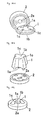
- a die called a porthole die as shown in Fig. 18A
- a die called a spider die as shown in Fig. 18B
- a die called a bridge die as shown in Fig. 18C .
- a male die 1 and a female die 2 are combined so that the mandrel 1a of the male die 1 is disposed in the corresponding die hole 2a of the female die 2 to define a circular extrusion hole by and between the mandrel 1a and the die hole 2a.
- the die it is configured such that a metal billet (metal material) pressed against the billet pressure receiving surface (metal material pressure receiving surface 1b) of the male die 1 is introduced in both the dies 1 and 2 via material introduction holes 1c and then passes through the extrusion hole while being plastically deformed, so that an extrusion molded article having a cross-section corresponding to the cross-sectional configuration of the extrusion hole is formed.
- extrusion molding dies for metal material as disclosed by the below-listed Patent Documents 1 and 2 have been conventionally proposed.
- the dies it is configured such that the billet pressure receiving surface of the male die is formed into a convex configuration protruded in a direction opposite to the billet extruding direction (i.e., protruded rearward) so that the pressing force of the metal billet to be applied to the billet pressure receiving surface can be received by a bridge portion of the male die.
- the extrusion molding die especially in the case of performing extrusion molding of a complicated configuration, it is required to smoothly introduce the metal material from the material introduction portion of the male die to the extrusion hole in a stable manner.
- the metal material to be flowed from the material introduction portion into between the male die and the female die is disturbed by the bridge portion of the male die, preventing smooth introduction of the metal material. This may deteriorate the dimensional accuracy of the extrusion molded article (extrusion molded product) to cause difficulty in obtaining high quality.
- the preferred embodiments of the present invention have been developed in view of the above-mentioned and/or other problems in the related art.
- the preferred embodiments of the present invention can significantly improve upon existing methods and/or apparatuses.
- the main purpose of the present invention is to solve the aforementioned problems of the prior arts and provide an extrusion molding die for metal material capable of attaining cost reduction and size reduction and also obtaining high quality extrusion molded article (extrusion molded product) while keeping sufficient strength and durability of the die.
- Other purposes of the present invention is to provide a production method of an extrusion molded article, a production method of a multi-passage hollow member, a production method of a tubular member, a die case for an extrusion molding die, an extrusion molding method for metal material, an extrusion molding apparatus for metal material, and related art, which can attain the aforementioned purposes.
- Other objects and advantages of the present invention will be apparent from the following preferred embodiments.
- the present invention has the structure summarized below.
- An extrusion molding die for metal material comprising:
- a production method of a multi-passage hollow member wherein the multi-passage hollow member is formed using the extrusion molding die as recited in the aforementioned Item 7.
- a die case for an extrusion molding die comprising a pressure receiving portion with an outer surface functioning as a metal material pressure receiving surface, wherein the die case is disposed so that the metal material pressure receiving surface faces rearward so as to oppose to an extrusion direction of the metal material, and a male die and a female die are mounted in the die case, wherein the pressure receiving surface is formed into a rearwardly protruded convex shape, and a plurality of metal material introducing portholes are formed in an external periphery of the pressure receiving portion at intervals in a circumferential direction around an axial center of the die case, wherein it is configured such that the metal material pressed against the metal material pressure receiving surface is introduced into the die case via the portholes and passes through the extrusion hole, and wherein B/A is adjusted to 1.8 to 6.0 and D/B is adjusted to 0.15 to 0.4, where "A" (product circumscribed circle diameter) is a diameter of a minimum circumscribed circle of a cross-section of an extrusion hole,
- An extrusion molding method for metal material comprising:
- the pressure receiving surface of the extrusion molding die is formed into a convex configuration, the pressing force of the metal material can be received by the pressure receiving surface in a dispersed manner when the metal material is pressed against the pressure receiving surface, which in turn can reduce the pressing force in the normal direction at each portion of the pressure receiving surface.
- the strength against the pressing force of the metal material can be improved, resulting in further improved durability.
- the material introducing portholes are formed in the pressure receiving portion of the die case covering the male die and the female die, i.e., the front end (downstream side) wall portion of the pressure receiving portion is integrally formed in the peripheral direction in a continuous manner. Therefore, the existence of the continuous peripheral wall portion further improves the strength of the die case, which in turn can further improve the strength of the entire extrusion molding die.
- the die according to the present invention there exists no portion weak in strength, such as a conventional bridge portion, and it is not required to increase the size such as a thickness to improve the strength beyond necessity. This enables reduction in size and weight, and also enables cost reduction.
- extrusion molding can be performed in a stable manner, and a further extended die life can be attained.
- extrusion molding can be performed in a more stable manner.
- the metal material can be introduced toward the extrusion hole evenly from the peripheral direction, which enables extrusion molding in a more stable manner.
- the durability can be improved more assuredly, and extrusion molding can be performed more smoothly.
- the metal material is pressed against the pressure receiving surface of a convex spherical surface constituted by a part of a spherical surface, since a compressing force toward the central axis of the pressure receiving portion is applied to each portion of the pressure receiving surface, the shearing force to be generated in the die case at the time of extrusion molding can be reduced more assuredly.
- a flat extrusion molded article can be formed with high dimensional accuracy.
- the metal material pressure receiving surface is constituted by a specific convex spherical surface
- the pressing force of the metal material against the pressure receiving surface can be dispersed more assuredly in a balanced manner, which can improve the strength against the metal material more assuredly.
- the metal material is pressed against the pressure receiving surface of a convex spherical surface constituted by a part of a spherical surface
- since compressing force toward the central axis of the pressure receiving portion is applied to each portion of the pressure receiving surface, the shearing force to be generated in the die case at the time of extrusion molding can be reduced more assuredly.
- an aluminum or aluminum alloy extrusion molded article can be produced.
- the pressing force of the metal material against the pressure receiving surface can be dispersed more assuredly in a balanced manner, which can improve the strength against the metal material more assuredly.
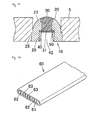
- the extrusion molding die 10 for metal material is configured to extrude a multi-passage hollow member 60 shown in Figs. 12 and 13 .
- the hollow member 60 is a metal member.
- the hollow member constitutes a heat exchanging tube made of aluminum or aluminum alloy.
- This hollow member 60 is a member for use in a heat exchanger, such as, e.g., a condenser for car air-conditioners, and has a flattened configuration having a width larger than a thickness.
- the hollow portion 61 of this hollow member 60 is divided into a plurality of heat exchanging passages 63 by a plurality of partitioning walls 62 extended in the tube length direction and arranged in parallel with each other. Thus, these passages 63 are extended in the tube length direction and arranged in parallel with each other.
- a direction with which the tube length direction perpendicularly intersects and along which the passages 63 are arranged will be referred to as a "width direction” or a “lateral direction,” and a direction with which the tube length direction perpendicularly intersects and with which the width direction perpendicularly intersects will be referred to as a "height direction (thickness direction)” or a “vertical direction.”
- a width direction or a “lateral direction”
- a direction with which the tube length direction perpendicularly intersects and with which the width direction perpendicularly intersects will be referred to as a “height direction (thickness direction)" or a “vertical direction.”
- the following explanation will be made by defining the "upstream side" of the extrusion direction as a “rear side” and the “downstream side” thereof as a "front side.”
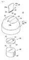
- Figs. 1 to 6 show an extrusion molding die 10 according to a first embodiment of the present invention.
- the extrusion molding die 10 is equipped with a die case 20, a male die 30, a female die 40, and a flow control plate 50.
- the die case 20 has a hollow structure, and is comprised of a dome-shaped pressure receiving portion 21 to be arranged at the upstream side (rear side) with respect to the extrusion direction of a metal billet as metal material and a base portion 25 to be arranged at the downstream side (front side).
- the surface thereof (rear surface) facing to a direction opposite to the extrusion direction of the metal billet constitutes a billet pressure receiving surface 22 as a metal material pressure receiving surface.
- This billet pressure receiving surface 22 is formed into a convex configuration protruded in a direction (i.e., in a rear direction) opposite to the extrusion direction, more specifically, a convex hemispherical surface configuration.
- the pressure receiving portion 21 is formed into a rearwardly protruded configuration.
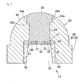
- a male die holding slit 23 communicated with the internal hollow portion (i.e., welding chamber 12) is formed along the central axis X1.
- This male die holding slit 23 is formed into a flat rectangular cross-sectional configuration corresponding to the cross-sectional configuration of the male die 30. Furthermore, as shown in Fig. 6 , at both side portions of the rear end side of the male die holding slit 23, engaging stepped portions 23a and 23a as engaging means for engaging the male die 30, which will be mentioned later, are formed.
- each porthole 24 is formed into a generally trapezoidal shape as seen from the upstream side of the axial direction (in a plan view).
- the pair of portholes 24 and 24 are arranged such that the outlet portions (i.e., front end portions) face an extrusion hole 11 which will be mentioned later.
- a between-hole-wall 27 is formed by the portion (wall portion) located between the pair of portholes 24 and 24 formed in the die case 20.
- Each porthole 24 is arranged such that the central axis X2 of the porthole 24 approaches the central axis X1 of the pressure receiving portion 21 as it advances toward the downstream side and intersects with the central axis X1 of the pressure receiving portion 21 in an inclined state.
- the detail structure such as, e.g., the inclination angle ⁇ of the central axis X2 of this porthole 24, and the dimensional ratio of prescribed portions, will be detailed later.
- the base portion 25 is integrally formed with the pressure receiving portion 21 and formed into a circular configuration centering on the axial center.
- the base portion 25 has a diameter larger than that of the pressure receiving portion 21.
- the base portion 25 and the pressure receiving portion 21 are not always required to be formed integrally, and can be formed separately. Whether both the portions 21 and 25 are to be formed integrally or separately can be arbitrarily decided in consideration of various factors, such as, e.g., maintenance efficiency.
- a female die holding hole 26 having a columnar shape (cylindrical shape) corresponding to the cross-sectional shape of the female die 40 and communicated with the inner welding chamber 12 is formed.
- the central axis of this female die holding hole 26 is configured so as to coincide with the central axis X1 of the die case 20.
- an engaging stepped portion 26a for engaging the female die 40 which will be explained later, via a flow control plate 50 is formed.
- the male die 30 is configured such that the front half principal portion thereof constitutes a mandrel 31.
- the front end portion of the mandrel 31 is configured to form the hollow portion 61 of the hollow member 60 and has a plurality of passage forming protruded portions 33 corresponding to the passages 63 of the hollowmember 60 respectively.
- These plural passage forming protruded portions 33 are arranged along the width direction of the mandrel 31 at predetermined intervals.
- Each gap formed between adjacent passage forming protruded portions 33 constitutes a partition forming groove 32 for forming the partition 62 of the hollow member 60.
- engaging protrusions 33a and 33a corresponding to the aforementioned engaging stepped portions 23a and 23a of the male die holding slit 23 formed in the die case 20 are integrally provided in a laterally protruded manner.
- This male die 30 is inserted into the male die holding slit 23 of the aforementioned die case 20 from the side of the billet pressure receiving surface 22 and fixed therein. At this time, the engaging protrusions 33a and 33a of the male die 30 are engaged with the engaging stepped portions 23a and 23a formed in the male die holding slit 23 to be positioned. Thus, the mandrel 31 of the male die 30 is held in a state in which the mandrel 31 of the male die 30 forwardly protrudes from the male die holding slit 23 in the die case 20 by a predetermined amount.
- the basal end face (i.e., rear end face) of the male die 30 is formed so as to constitute a part of the convex hemispherical surface corresponding to the billet pressure receiving surface 22 of the die case 20, so that the basal end face (i.e. , rear end face) of the male die 30 and the billet pressure receiving surface 22 form a prescribed smooth convex hemispherical surface.
- the basal end face of the male die 30 it is not always required to form the basal end face of the male die 30 as a part of the hemispherical surface, and the configuration of the basal end face is not specifically limited.
- the basal end face of the male die 30 is 1/3 or less of the surface area of the billet pressure receiving surface 22, it canbe constituted such that the basal end face of the male die 30 is formed by a part of a cylindrical external peripheral surface in which the basal end face of the male die 30 is formed to have a circular arc shape in the longitudinal direction (width direction) corresponding to the billet pressure receiving surface 22 and a linear shape in the traverse direction (thickness direction).
- the female die 40 has a cylindrical shape. As shown in Fig. 2 , at its both sides of the peripheral surface, key protrusions 47 and 47 extended in parallel with the central axis are formed.
- the female die 40 is provided with a die hole (bearing hole 41) opened to the rear end face side thereof and formed corresponding to the mandrel 31 of the male die 30, and a relief hole 42 communicated with the die hole 41 and opened to the front end face side thereof.
- the die hole 41 is provided with an inwardly protruded portion along the inner peripheral edge portion so that an outer peripheral portion of the hollow member 60 can be defined.
- the relief hole 42 is formed into a tapered shape which gradually increases in thickness (height) toward the front end side (downstream side) and opened at the downstream side.
- the flow control plate 50 is formed to have a round external peripheral shape corresponding to the cross-sectional shape of the female die holding hole 26 of the die case 20.
- a central through-hole 51 is formed at the center of the flow control plate 50.
- the flow control plate 50 has, at its both sides of the external peripheral edge portion, key protrusions 57 and 57 corresponding to the key protrusions 47 and 47 of the female die 40 are formed.
- the female die 40 is mounted and secured in the female die holding hole 26 of the die case 20 via the flow control plate 50.
- the external periphery of one end face (rear end face) of the female die 40 is engaged with the engaging stepped portion 26a of the female die holding hole 26 via the external peripheral edge portion of the flow control plate 50, so that the female die 40 and the flow control plate 50 are positioned in the axial direction.
- the key protrusions 47 and 47 of the female die 40 and the key protrusions 57 and 57 of the flow control plate 50 are engaged with the keyways (not illustrated) formed in the inner peripheral surface of the female die holding hole 26 to be positioned in the circumference direction about the central axis.
- the mandrel 31 of the male die 30 and the die hole 41 of the female die 40 are positioned in the central through-hole 51 of the flow control plate 50.
- the mandrel 31 of the male die 30 is positioned within the die hole 41 of the female die 40, which forms a flat circular extrusion hole 11 by and between the mandrel 31 and the die hole 41.
- This extrusion hole 11 is formed to have a cross-sectional configuration corresponding to the cross-sectional configuration of the hollow member 60 to be formed in which a plurality of partition forming grooves 32 of the mandrel 31 are arranged in parallel in the widthwise direction.
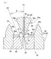
- the central axes X2 of the portholes 24 and 24 are set to be inclined with respect to the central axis X1 of the die case 20 respectively as it advances toward the downstream side.
- the inclination angle ⁇ of the central axis X2 of the porthole 24 with respect to the central axis X1 of the die case 20 is set to 3 to 45°, more preferably 10 to 35°, still more preferably 15 to 30°.
- the metal material flows through the portholes 24 and 24 and the welding chamber 12 in a stable manner, and then smoothlypasses through the entire periphery of the extrusion hole 11 in a balanced manner.
- a high quality extrusion molded article excellent in dimensional accuracy can be formed.
- the metal material passed through the portholes 24 and 24 and the welding chamber 12 cannot be smoothly introduced into the extrusion hole 11, which may sometimes make it difficult to stably obtain a high quality extrusion molded article.
- the inclination angle ⁇ is too large, the material flowing direction of the porthole 24 with respect to the material extrusion direction inclines largely, which increases the extrusion resistance of the metal material, and therefore it is not preferable.
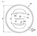
- the diameter of the minimum circumscribed circle of the cross-section of the hollow member 60 as an extrusion molded product (extrusion molded article) as shown by the imaginary line in Fig. 13 is defined as "A" (product circumscribed circle diameter) and that the external diameter of the metal material pressure receiving surface 22 in a state in which the pressure receiving surface 22 is seen from the upstream side in the axial center direction as shown in Fig. 3 (in a top view state) is defined as "B" (pressure receiving surface external diameter), it is required to adj ust B/A to 1. 8 to 6.0 (1.8 ⁇ B/A ⁇ 6.0).
- B/A is adjusted to 2.0 to 5.0, more preferably 2.0 to 4.5.
- the porthole inlet side minimum thickness size of the between-hole-wall 27 formed by the wall portion between the pair of portholes 24 and 24 as shown in Fig. 3 is defined as "C" (between-hole-wall inlet side minimum thickness size)
- the between-hole-wall inlet side total thickness size obtained by multiplying the number "n" of the between-hole-walls 27 by the between-hole-wall inlet side minimum thickness size "C” is defined as "D”
- D/B is adjusted to 0.15 to 0.35, more preferably 0.15 to 0.3.
- the porthole outlet side minimum thickness size of the between-hole-wall 27 is defined as "E" (between-hole-wall outlet side minimum thickness size) as shown in Fig. 8 .
- E/C is adjusted to 0.15 to 1.0 (0.15 ⁇ E/C ⁇ 1.0).
- E/C is adjusted to 0.15 to 0.8, more preferably 0.15 to 0.7.
- E/C is adjusted so as to fall within the aforementioned specific range, extrusion can be performed in a stable manner while securing sufficient strength of the die case 20.
- E/C is too small, the between-hole-wall 27 cannot withstand against the extrusion load, which may cause deteriorated strength of the die case 20.
- E/C is excessively large, the extrusion load increases excessively, resulting in unsmooth introduction of the metal material into the die, which may make it difficult to perform the extrusion in a stable state.
- the billet pressure receiving surface 22 of the die case 20 has a convex spherical surface of 1/6 sphere to a 4/6 sphere.
- the billet pressure receiving surface 22 is formed into the aforementioned specific convex spherical configuration, the pressing force of the metal billet can be assuredly received by the billet pressure receiving surface 22 in a well-balanced dispersed manner, resulting in sufficient strength, which in turn can extend the die life more assuredly.
- the billet pressure receiving surface 22 is formed by a configuration constituted by a convex spherical surface of a sphere smaller than a 1/6 sphere, such as, e.g., a convex spherical surface constituted by a 1/8 sphere, sufficient strength against billet pressing force cannot be obtained, which may cause deteriorated die life due to generation of cracks.
- the billet pressure receiving surface 22 is formed into a configuration constituted by a convex spherical surface of a sphere exceeding a 4/6 sphere, such as, e.g., a convex spherical surface configuration of a 5/6 sphere, the cost may be increased due to the complicated configuration.
- the sphere with a ratio such as, e.g. , a 1/8 sphere, a 1/6 sphere, or a 4/6 sphere, is defined by a partial sphere obtained by cutting a perfect sphere with a plane perpendicular to the central axis of the perfect sphere.
- an "m/M sphere (“m” and “M” are natural numbers, and m ⁇ M) " is defined by a partial sphere obtained by cutting a perfect sphere with a plane perpendicular to the central axis of the perfect sphere at a position where a distance from a surface of the perfect sphere to an inner position of the perfect sphere on the central axis (diameter) is m/M, where the length of the central axis (diameter) of the perfect sphere is "1.”
- the inner side surface 24a and the outer side surface 24b among the inner periphery of the porthole 24 are arranged in parallel or generally in parallel with each other and also in parallel or generally in parallel to the central axis A2 of the porthole 24. Furthermore, the inner side surface 24a and the outer side surface 24b of the porthole inner periphery are each constituted as an inclined surface (tapered surface) inclined to the central axis X1 of the die case 20.
- the extrusion molding die 10 structured as mentioned above is set to an extruder as shown in Figs. 9 to 11 . That is, the extrusion molding die 10 of this embodiment is set to a container 6 with the die attached to the die mounting hole 5a formed in the center of the plate 5. The extrusion molding die 10 is fixed in a direction perpendicular to the extrusion direction by the plate 5 and also fixed in the extrusion direction by the backer (not illustrated) .
- a metal billet (metal material), such as, e.g. , an aluminum or aluminum alloy billet, inserted in the container 6 is pressed in the right direction in Fig. 9 (i.e., in the extrusion direction) via a dummy block 7.
- the metal billet is pressed against the billet pressure receiving surface 22 of the die case 20 of the extrusion molding die 10 to be plastically deformed.
- the metal material passes through the pair of portholes 24 and 24 while being plastically deformed and then reaches the welding chamber 12 of the die case 20.
- the metal material is forwardly extruded through the extrusion hole 11 into a cross-sectional configuration corresponding to the opening configuration of the extrusion hole 11.
- a metal extrusion molded product multi-passage hollow member 60
- the billet pressure receiving surface 22 is formed into a convex spherical configuration, when the metal billet is pressed against the billet pressure receiving surface 22, the pressing force can be received by the pressure receiving surface 22 in a dispersed manner. Therefore, the pressing force to be applied to each portion of the billet pressure receiving surface 22 in the direction of a normal line can be reduced, thereby increasing the strength against the pressing force of the metal material. As a result, sufficient durability can be attained.
- theratioB/Aofthepressure receiving surface external diameter B to the product circumscribed circle diameter A, the ratio D/B of the between-hole-wall inlet side total thickness size D to the receiving pressure surface diameter B, and the ratio E/C of the between-hole-wall outlet side minimum thickness size E to the between-hole-wall inlet side minimum thickness size C are adjusted so as to fall within the aforementioned optimum ranges. Therefore, sufficient strength of the die case 20 can be secured, and stable extrusionmolding can be performed smoothly while attaining the long die life.
- the portholes 24 for introducing materials are formed in the pressure receiving portion 21 of the die case 20 covering the male die 30 and the female die 40.
- the front end wall portion of the pressure receiving portion 21 and the wall portion of the base portion 25 are formed integrally and continuously in the peripheral direction. Therefore, the existence of this continued peripheral wall portion can further increase the strength of the die case 20, which in turn can further increase the strength of the entire extrusion molding die. Accordingly, there exists no portion weak in strength, such as a conventional bridge portion, and it is not required to increase the size, such as, e.g., the thickness, beyond the necessity for the purpose of increasing the strength, which makes it possible to attain the size and weight reduction as well as the cost reduction.
- the portholes 24 and 24 are formed at positions away from the central axis X1 of the pressure receiving portion 21, i.e., at the external periphery of the pressure receiving portion 21, and the central axis X2 of each porthole 24 is inclined with respect to the central axis X1 of the die case 20 so as to gradually approach the central axis X1 of the die case 20 toward the downstream side. Therefore, the metal material passing through the portholes 24 and 24 can be stably extruded while being smoothly introduced toward the central axis X1, i.e., the extrusion hole 11. Furthermore, in this embodiment, since the downstream side end portions (outlets) of the portholes 24 and 24 are arranged so as to face to the extrusion hole 11, the metal material can be more smoothly introduced into the extrusion hole 11.
- the metal material can be more smoothly introduced into the extrusion hole 11 in a stable manner from both the thickness sides. Accordingly, the metal material will be extruded while evenly passing through the entire area of the extrusion hole 11 in a well-balanced manner, to thereby obtain a high quality extrusion molded hollow member 60.
- the metal material can be introduced into the entire region of the extrusion hole 11 in a balanced manner, which makes it possible to assuredly maintain the high quality.
- the die life could be extended sufficiently as compared with a conventional one.
- the extrusion limit speed can be raised considerably.
- the upper limit of the extrusion speed was 60 m/min.
- the upper limit of the extrusion speed can be raised up to 150 m/min, i.e., the extrusion limit speed can be raised about 2.5 times, and therefore the further improved productive efficiency can be expected.
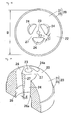
- Figs. 14 to 17 show an extrusion molding die according to a second embodiment of the present invention.
- the extrusion molding die 10 of this second embodiment is used to extrude a tubular member circular in cross-section, which is different from the extrusion molding die 10 of the first embodiment configured to extrude a flat extrusion molded tube.
- each porthole 24 is arranged such that each porthole 24 approaches the central axis of the pressure receiving portion 21 at it advances toward the downstream side so that the central axis of the porthole 24 intersects with and is inclined to the central axis of the pressure receiving portion 21.
- the optimum range of the inclination angle of the porthole central axis to the central axis of the pressure receiving portion 21 is the same as mentioned above.
- the male die 30 has a round mandrel 31, and the female die 40 has a round die hole 41.
- the die holding hole 23 of the die case 20 is formed into a cylindrical column shape corresponding to the male die 30.
- the mandrel 31 of the male die 30 is disposed in the die hole 41 of the female die 40, so that a circular ring shaped extrusion hole 11 is formed by and between the mandrel 31 and the die hole 41.
- the porthole inlet side minimum thickness size of the between-hole-wall 27 formed by the wall portion between the adjacent portholes 24 in the circumferential direction is defined as "C" (between-hole-wall inlet side minimum thickness size)
- the number "n" of the between-hole-walls 27 is "3.”
- the other structure of the extrusion molding die 10 of this second embodiment is essentially the same as that of the extrusion molding die 10 of the aforementioned first embodiment, and therefore the cumulative explanation will be omitted by allotting the same reference numeral to the same or corresponding portion.
- extrusion molding die 10 of this second embodiment it is set to the same extruder as in the first embodiment as shown in Figs. 9 to 11 to perform extrusion molding to thereby produce a tubular member around in cross-section.
- the pressure receiving portion 21 is formed to have a hemispherical convex shape.
- the configuration of the pressure receiving portion (pressure receiving surface) is not limited to it.
- the pressure receiving surface can be formed into a polyhedral configuration constituted by a number of sides.
- it can be formed into a polyhedral configuration such as a multi-sided pyramid in which a plurality of sides are arranged in the peripheral direction or a polyhedral configuration in which a plurality of sides are arranged in the radial direction.
- each side constituting the pressure receiving surface can be flat or curved.
- the pressure receiving portion can be formed into a laterally extended configuration in which the lateral directional length is longer than the lengthwise directional length, the lateral direction and the vertical direction being perpendicular to the axial direction, such as, e.g., a laterally elongated elliptical configuration as seen from the upstream side of the axial direction or a laterally elongated oval configuration as seen from the upstream side of the axial direction.
- the pressure receiving portion can be formed into a configuration having a protrusion size along the axial direction longer than the size of the radial direction perpendicular to the axial direction, e.g., a semi-elliptical configuration obtained by halving an elliptical configuration in the major axis direction.
- the die case 20 is integrally formed.
- the die case can be divided into two members.
- the die case consists of two members, i.e., a male die case for holding a male die and a female die case for holding a female die.
- the male die, the female die and the flow control plate are formed separately from the die case.
- the present invention is not limited to the above, and can be constituted such that at least one of the male die, the female die and the flow control plate is formed integrally with the die case. Furthermore, in the present invention, the flow control plate can be omitted as needed.
- the explanation is directed to the case in which two or three portholes are formed.
- the present invention is not limited to the above. In the present invention, it can be constituted that four or more portholes are formed.
- the configuration of the porthole inlet is not specifically limited. It can be configured such that portholes are different in configuration from each other.
- it can be formed such that the opening area of the porthole inlet is larger than the passage cross-sectional area of the inside portion the porthole.
- the base portion is formed at the front end portion of the die case. In the present invention, however, it is not necessarily required to provide such a base portion.
- An extrusion molding die 10 corresponding to the aforementioned first embodiment shown in Figs. 1 to 8 was prepared.
- the male die 30 of this die 10 it was regulated such that the mandrel 31 was 2.0 mm in thickness, and 19.2 mm in width, the passage forming protruded portion 33 was 1.2 mm in height and 0.6 mm in width, and the partition forming groove was 0.2 mm in width.
- the die hole 41 was 1.7 mm in height and 20.0 mm in width.
- each porthole 24 was adjusted to 10°. That is, the inclination angle ⁇ of the axial center X2 of each porthole 24 with respect to the axial center X1 of the die case 20 was adjusted to 10° and the inner and outer side surfaces 24a and 24b among the inner peripheral surface of each porthole 24 were arranged in parallel with each other.
- the billet pressure receiving surface 22 was formed into an external spherical surface (protruded spherical surface) of a 1/2 sphere with radius 30 mm.
- the ratio (B/A) of the pressure receiving surface external diameter B to the product circumscribed circle diameter A was adjusted to 1.8; the ratio D/B of the between-hole-wall inlet side total thickness size D to the pressure receiving surface external diameter B was adjusted to 0.3; and the ratio E/C of the between-hole-wall outlet side minimum thickness size E to the between-hole-wall inlet side minimum thickness size C was adjusted to 0.2.
- the extrusion molding die 10 structured as mentioned above was set to the extruder similar to that of the aforementioned embodiment as shown in Figs. 9 to 11 , and extrusion molding was performed to produce a flat multi-passage tubular member (heat exchanging tubular member) made of aluminum alloy as shown in Figs. 12 and 13 .
- the die life (the amount (tons) of material introduced until cracks or abrasion occurred in the die) and the extrusion load were measured. Furthermore, the die life limiting factors were investigated. The results are shown in Table 1.
- the ratio (B/A) of the pressure receiving surface external diameter B to the product circumscribed circle diameter A was adj usted to 2.0 as shown in Table 1.
- the ratio (B/A) of the pressure receiving surface external diameter B to the product circumscribed circle diameter A was adj usted to 3.0 as shown in Table 1.
- the ratio (B/A) of the pressure receiving surface external diameter B to the product circumscribed circle diameter A was adjusted to 4.0 as shown in Table 1.
- the ratio (B/A) of the pressure receiving surface external diameter B to the product circumscribed circle diameter A was adj usted to 4.5 as shown in Table 1.
- the ratio (B/A) of the pressure receiving surface external diameter B to the product circumscribed circle diameter A was adj usted to 5.0 as shown in Table 1.
- the ratio (B/A) of the pressure receiving surface external diameter B to the product circumscribed circle diameter A was adj usted to 5.5 as shown in Table 1.
- the ratio (B/A) of the pressure receiving surface external diameter B to the product circumscribed circle diameter A was adjusted to 6.0 as shown in Table 1.
- the ratio (B/A) of the pressure receiving surface external diameter B to the product circumscribed circle diameterA was adj usted to 1.5 as shown in Table 1.
- the ratio (B/A) of the pressure receiving surface external diameter B to the product circumscribed circle diameter A was adjusted to 7.0 as shown in Table 1.
- Example 1-1 Although minute cracks were included as a die life limiting factor, the extrusion load was low, and the die life was relatively long.
- Comparative Examples in addition to abrasion of the male die, minute cracks were one of die life limiting factors, and the die life was short. Among other things, in Comparative Example 1-1, the die life was considerably short because of the lack of strength. In Comparative Example 1-2, although the strength was sufficient, the extrusion load became large, which caused short die life.
- the ratio (B/A) of the pressure receiving surface external diameter B to the product circumscribed circle diameter A was adjusted to 2.5 as as shown in Table 2, the ratio D/B of the between-hold-wall inlet side total thickness size D to the pressure receiving surface external diameter B was adjusted to 0.15; and the ratio E/C of the between-hole-wall outlet side minimum thickness size E to the between-hole-wall inlet side minimum thickness size C was adjusted to 0.2.
- the ratio D/B of the between-hole-wall inlet side total thickness size D to the pressure receiving surface external diameter B was adjusted to 0.2 as shown in Table 2.
- the ratio D/B of the between-hole-wall inlet side total thickness size D to the pressure receiving surface external diameter B was adjusted to 0.3 as shown in Table 2.
- the ratio D/B of the between-hole-wall inlet side total thickness size D to the pressure receiving surface external diameter B was adjusted to 0.35 as shown in Table 2.
- the ratio D/B of the between-hole-wall inlet side total thickness size D to the pressure receiving surface external diameter B was adjusted to 0.4 as shown in Table 2.
- the ratio D/B of the between-hole-wall inlet side total thickness size D to the pressure receiving surface external diameter B was adjusted to 0.1 as shown in Table 2.
- the ratio D/B of the between-hole-wall inlet side total thickness size D to the pressure receiving surface external diameter B was adjusted to 0.45 as shown in Table 2.
- Comparative Example 2-1 minute cracks in the male die were the die life limiting factor, and the die life was short.
- Comparative Example 2-2 the extrusion load was large, and the die life was short.
- the ratio E/C of the between-hole-wall outlet side minimum thickness size E to the between-hole-wall inlet side minimum thickness size C was adjusted to 0.2 as shown in Table 3.
- the ratio E/C of the between-hole-wall outlet side minimum thickness size E to the between-hole-wall inlet side minimum thickness size C was adjusted to 0.6 as shown in Table 3.
- the ratio E/C of the between-hole-wall outlet side minimum thickness size E to the between-hole-wall inlet side minimum thickness size C was adjusted to 0.8 as shown in Table 3.
- the ratio E/C of the between-hole-wall outlet side minimum thickness size E to the between-hole-wall inlet side minimum thickness size C was adjusted to 1.0 as shown in Table 3. Only in this example, the inclination angle of the inner side surface 24a among the inner peripheral surface of each porthole 24 was adjusted to 0° with respect to the axial center X1 of the die case 20.
- the ratio E/C of the between-hole-wall outlet side minimum thickness size E to the between-hole-wall inlet side minimum thickness size C was adjusted to 0.1 as shown in Table 3.
- the ratio E/C of the between-hole-wall outlet side minimum thickness size E to the between-hole-wall inlet side minimum thickness size C was adjusted to 1.1 as shown in Table 3. Furthermore, only in this comparative example, the inner side surface 24a of the inner peripheral surface of each porthole 24 was inclined by 10° with respect to the axial center X1 of the die case 20 so as to get away from the axial center X1 of the die case 20 as it advances toward the downstream side.
- Comparative Example 3-1 minute cracks in the male die was the die life limiting factor, and the die life was slightly shorter than that of Examples.
- Comparative Example 3-2 although the extrusion load was large, a die life nearly equal to that of Example was obtained.
- An extrusion molding die 10 corresponding to the aforementioned first embodiment shown in Figs. 1 to 8 was prepared.
- a die case 20 for this die 10 in which the billet pressure receiving surface 22 was formed into a 1/8 spherical configuration (protruded spherical surface) having a radius of 45.4 mm was prepared.
- the diameter of this pressure receiving portion 21 was adjusted to 60 mm.
- each porthole 24 was formed at the both thickness sides of the extrusion hole 11 in the die case 20.
- the inclination angle ⁇ of each porthole 24 was adjusted to 10°.
- a male die 30 in which the height (thickness) of the mandrel 31 was adjusted to 2.0 mm, the width of the mandrel 31 was adjusted to 19.2mm, the height of the passage forming protruded portion 33 was adjusted to 1.2 mm, the width of the passage forming protruded portion 33 was adjusted to 0.6 mm, and the width of the partition forming groove 32 was adjusted to 0.2 mm. Furthermore, as a female die, a female die 40 in which the height of the die hole 41 was adjusted to 1.7 mm and the width of the die hole 41 was adjusted to 20.0 mm.
- the ratio (B/A) of the pressure receiving surface external diameter B to the product circumscribed circle diameter A was adjusted to 3.0
- the ratio D/B of the between-hole-wall inlet side total thickness size D to the pressure receiving surface external diameter B was adjusted to 0.3
- the ratio E/C of the between-hole-wall outlet side minimum thickness size E to the between-hole-wall inlet side minimum thickness size C was adjusted to 0.2.
- the extrusion molding die 10 was set to an extruder similar to the extruder shown in the first embodiment, and extrusion was performed to produce a flat multi-passage tubular member (heat exchanging tubular member) as shown in Figs. 12 and 13 .
- an extrusion molding die 10 which was the same as the extrusion molding die of Example 4-1 except that the billet pressure receiving surface 22 was constituted by a 1/6 spherical surface and the radius was set to 40.3 mm was prepared.
- the extrusion molding die 10 was set to the same extruder as mentioned above, and extrusion was performed to produce a flat multi-passage tubular member.
- an extrusion molding die 10 which was the same as the extrusion molding die of Example 4-1 except that the billet pressure receiving surface 22 was constituted by a 1/3 convex spherical surface and the radius was set to 32.0mm was prepared.
- the extrusion molding die 10 was set to the same extruder as mentioned above and extrusion was performed to produce a flat multi-passage tubular member.
- an extrusion molding die 10 which was the same as the extrusion molding die of Example 4-1 except that the billet pressure receiving surface 22 was constituted by a 1/2 convex spherical surface and the radius was set to 30.0mm was prepared.
- the extrusion molding die 10 was set to the same extruder as mentioned above and extrusion was performed to produce a flat multi-passage tubular member.
- an extrusion molding die 10 which was the same as the extrusion molding die of Example 4-1 except that the billet pressure receiving surface 22 was constituted by a 4/6 convex spherical surface and the radius was set to 32.0mm was prepared.
- the extrusion molding die 10 was set to the same extruder as mentioned above and extrusion was performed to produce a flat multi-passage tubular member.
- an extrusion molding die 10 which was the same as the extrusion molding die of Example 4-1 except that the billet pressure receiving surface 22 was constituted by a 5/6 convex spherical surface and the radius was set to 40.3mm was prepared.
- the extrusion molding die 10 was set to the same extruder as mentioned above and extrusion was performed to produce a flat multi-passage tubular member.
- the die life could be extended and the die production cost could be reduced.
- the die production cost could be reduced while keeping sufficient long die life, which was excellent in result.
- Example 4-5 Comparing with the die of Example 4-4, in the die (Example 4-5) in which the billet pressure receiving surface 22 was formed into a 4/6 convex spherical configuration, the die production cost slightly increased and the results were slightly not good among the dies of Examples 4-2 to 4-5.
- the term "preferably” is non-exclusive and means “preferably, but not limited to.”
- means-plus-function or step-plus-function limitations will only be employed where for a specific claim limitation all of the following conditions are present in that limitation: a) "means for” or “step for” is expressly recited; b) a corresponding function is expressly recited; and c) structure, material or acts that support that structure are not recited.
- the terminology "present invention” or “invention” may be used as a reference to one or more aspect within the present disclosure.
- the extrusion molding die according to the present invention can be preferably used in manufacturing an extrusion molded product, such as, e.g., a hollow tube, more specifically, a heat exchanging tube for use in, e.g., automobile air-conditioning gas coolers, evaporators, household hot-water supplying apparatuses.
- an extrusion molded product such as, e.g., a hollow tube, more specifically, a heat exchanging tube for use in, e.g., automobile air-conditioning gas coolers, evaporators, household hot-water supplying apparatuses.
Landscapes
- Engineering & Computer Science (AREA)
- Mechanical Engineering (AREA)
- Extrusion Of Metal (AREA)
Abstract
Description
- The present invention relates to an extrusion molding die for metal material for use in extruding metal material, and its related art.
- As an extrusion molding die for use in manufacturing a metallic hollow extrusion molded product, such as, e.g., an aluminum heat exchanging tube for use in car air-conditioning heat exchangers, there are a die called a porthole die as shown in
Fig. 18A , a die called a spider die as shown inFig. 18B , or a die called a bridge die as shown inFig. 18C . - In these extrusion molding dies, a
male die 1 and afemale die 2 are combined so that themandrel 1a of themale die 1 is disposed in thecorresponding die hole 2a of thefemale die 2 to define a circular extrusion hole by and between themandrel 1a and thedie hole 2a. In the die, it is configured such that a metal billet (metal material) pressed against the billet pressure receiving surface (metal materialpressure receiving surface 1b) of themale die 1 is introduced in both thedies material introduction holes 1c and then passes through the extrusion hole while being plastically deformed, so that an extrusion molded article having a cross-section corresponding to the cross-sectional configuration of the extrusion hole is formed. - In such extrusion molding dies, large stress due to pressing of the metal billet is applied to the billet
pressure receiving surface 1b of themale die 1, causing generation of cracks in the periphery of the pressure receiving portion of the die by the stress, which may sometimes make it difficult to attain sufficiently long die life. - Under the circumstances, conventionally, extrusion molding dies for metal material as disclosed by the below-listed
Patent Documents - Patent Document 1: Japanese Unexamined Laid-open Utility Model Publication No.
S53-102938 Figs. 3 to 5 ) - Patent Document 2: Japanese Examined Laid-open Patent Publication No.
H06-81644 - In the conventional extrusion molding dies disclosed in the
aforementioned Patent Documents - Furthermore, in the extrusion molding die, especially in the case of performing extrusion molding of a complicated configuration, it is required to smoothly introduce the metal material from the material introduction portion of the male die to the extrusion hole in a stable manner. In the aforementioned extrusion molding die, however, the metal material to be flowed from the material introduction portion into between the male die and the female die is disturbed by the bridge portion of the male die, preventing smooth introduction of the metal material. This may deteriorate the dimensional accuracy of the extrusion molded article (extrusion molded product) to cause difficulty in obtaining high quality.
- The preferred embodiments of the present invention have been developed in view of the above-mentioned and/or other problems in the related art. The preferred embodiments of the present invention can significantly improve upon existing methods and/or apparatuses.
The main purpose of the present invention is to solve the aforementioned problems of the prior arts and provide an extrusion molding die for metal material capable of attaining cost reduction and size reduction and also obtaining high quality extrusion molded article (extrusion molded product) while keeping sufficient strength and durability of the die. - Other purposes of the present invention is to provide a production method of an extrusion molded article, a production method of a multi-passage hollow member, a production method of a tubular member, a die case for an extrusion molding die, an extrusion molding method for metal material, an extrusion molding apparatus for metal material, and related art, which can attain the aforementioned purposes.
Other objects and advantages of the present invention will be apparent from the following preferred embodiments. - The present invention has the structure summarized below.
- [1] An extrusion molding die for metal material, comprising:
- a die case having a pressure receiving portion with an outer surface functioning as a metal material pressure receiving surface, wherein the die case is disposed so that the metal material pressure receiving surface faces rearward so as to oppose to an extrusion direction of the metal material:
- a male die mounted in the die case; and
- a female die mounted in the die case so as to form an extrusion hole by and between the female die and the male die,
- wherein the pressure receiving surface is formed into a rearwardly protruded convex shape, and a plurality of metal material introducing portholes are formed in an external periphery of the pressure receiving portion at intervals in a circumferential direction around an axial center of the die case,
- wherein it is configured such that the metal material pressed against the metal material pressure receiving surface is introduced into the die case via the portholes and passes through the extrusion hole, and
- wherein B/A is adjusted to 1.8 to 6.0 and D/B is adjusted to 0.15 to 0.4, where "A" (product circumscribed circle diameter) is a diameter of a minimum circumscribed circle of a cross-section of an extrusion molded product, "B" (pressure receiving surface external diameter) is an external diameter of the metal material pressure receiving surface, "C" (between-hole-wall inlet side minimum thickness size) is a porthole inlet side minimum thickness size of a between-hole-wall formed by a wall portion between a pair of adjacent portholes, "n" is the number of the between-hole-walls, and "D" is a between-hole-wall inlet side total thickness size obtained by multiplying the number "n" of the between-hole-walls by the between-hole-wall inlet side minimum thickness size "C."
- [2] The extrusion molding die for metal material as recited in the
aforementioned Item 1, wherein E/C is adjusted to 0.15 to 1.0, where "E" (between-hole-wall outlet side minimum thickness size) is a porthole outlet side minimum thickness size of the between-hole-wall. - [3] The extrusion molding die for metal material as recited in the
aforementioned Item - [4] The extrusion molding die for metal material as recited in any one of the
aforementioned Items 1 to 3, wherein the pressure receiving surface of the die case is formed into a convex spherical surface constituted by a part of a spherical surface. - [5] The extrusion molding die for metal material as recited in any one of the
aforementioned Items 1 to 4, wherein an inclination angle of an axial center of the porthole is set to 3 to 45° with respect to an axial center of the die case. - [6] The extrusion molding die for metal material as recited in any one of the
aforementioned Items 1 to 5, wherein the extrusion hole is formed into a flat shape with a width larger than a height (thickness) , and wherein the portholes are formed at positions corresponding to both thickness sides of the extrusion hole. - [7] The extrusion molding die for metal material as recited in any one of the
aforementioned Items 1 to 6, wherein a flat circular extrusion hole with a width larger than a height (thickness) is formed by and between the male die and the female die, wherein a portion of the male die corresponding to the extrusion hole is formed into a comb-like configuration having a plurality of passage forming protrusions arranged in a width direction, and
wherein a multi-passage hollow member having a plurality of passages arranged in a width direction is formed when metal material passes through the extrusion hole. - [8] The extrusion molding die as recited in any one of the
aforementioned Items 1 to 5, wherein the male die and the female die form a circular extrusion hole, and wherein a tubular member circular in cross-section is formed when metal material passes through the extrusion hole. - [9] The extrusion molding die as recited in any one of the
aforementioned Items 1 to 8, wherein the metal material pressure receiving surface is constituted by a convex spherical surface of a 1/6 sphere to a 4/6 sphere. - [10] The extrusion molding die as recited in any one of the
aforementioned Items 1 to 9, wherein the metal material is aluminum or its alloy. - [11] A production method of an extrusion molded article, wherein the extrusion molded article is formed using the extrusion molding die as recited in any one of the
aforementioned Items 1 to 10. - [12] A production method of a multi-passage hollow member, wherein the multi-passage hollow member is formed using the extrusion molding die as recited in the
aforementioned Item 7. - [13] A production method of a tubular member circular in cross-section, wherein the tubular member is formed using the extrusion molding die as recited in the aforementioned Item 8.
- [14] A die case for an extrusion molding die, comprising a pressure receiving portion with an outer surface functioning as a metal material pressure receiving surface, wherein the die case is disposed so that the metal material pressure receiving surface faces rearward so as to oppose to an extrusion direction of the metal material, and a male die and a female die are mounted in the die case,
wherein the pressure receiving surface is formed into a rearwardly protruded convex shape, and a plurality of metal material introducing portholes are formed in an external periphery of the pressure receiving portion at intervals in a circumferential direction around an axial center of the die case,
wherein it is configured such that the metal material pressed against the metal material pressure receiving surface is introduced into the die case via the portholes and passes through the extrusion hole, and
wherein B/A is adjusted to 1.8 to 6.0 and D/B is adjusted to 0.15 to 0.4, where "A" (product circumscribed circle diameter) is a diameter of a minimum circumscribed circle of a cross-section of an extrusion molded product, "B" (pressure receiving surface external diameter) is an external diameter of the metal material pressure receiving surface, "C" (between-hole-wall inlet side minimum thickness size) is a porthole inlet side minimum thickness size of a between-hole-wall formed by a wall portion between a pair of adjacent portholes, "n" is the number of the between-hole-walls, and "D" is a between-hole-wall inlet side total thickness size obtained by multiplying the number "n" of the between-hole-walls by the between-hole-wall inlet side minimum thickness size "C." - [15] The die case for an extrusion molding die as recited in the aforementioned Item 14,
wherein the metal material pressure receiving surface is constituted by a convex spherical surface of a 1/6 sphere to a 4/6 sphere. - [16] An extrusion molding method for metal material, comprising:
- preparing a die case having a pressure receiving portion with an outer surface functioning as a metal material pressure receiving surface, wherein the die case is disposed so that the metal material pressure receiving surface faces rearward so as to oppose to an extrusion direction of the metal material; a male die mounted in the die case; and a female die mounted in the die case so as to form an extrusion hole by and between the female die and the male die;
- forming the pressure receiving surface into a rearwardly protruded convex shape;
- forming a plurality of metal material introducing portholes in an external periphery of the pressure receiving surface arranged at intervals in a circumferential direction around an axial center of the die case;
- adjusting B/A to 1.8 to 6.0 and D/B to 0.15 to 0.4, where "A" (product circumscribed circle diameter) is a diameter of a minimum circumscribed circle of a cross-section of an extrusion molded product, "B" (pressure receiving surface external diameter) is an external diameter of the metal material pressure receiving surface, "C" (between-hole-wall inlet side minimum thickness size) is a porthole inlet side minimum thickness size of a between-hole-wall formed by a wall portion between a pair of adjacent portholes, "n" is the number of the between-hole-walls, and "D" is a between-hole-wall inlet side total thickness size obtained by multiplying the number "n" of the between-hole-walls by the between-hole-wall inlet side minimum thickness size "C"; and
- introducing the metal material pressed against the metal material pressure receiving surface into the die case via the portholes to pass through the extrusion hole.
- [17] An extruder for metal material equipped with a container and an extrusion molding die set to the container, and configured to supply metal material in the container to the extrusion molding die,
wherein the extrusion molding die comprises: - a die case having a pressure receiving portion with an outer surface functioning as a metal material pressure receiving surface, wherein the die case is disposed so that the metal material pressure receiving surface faces rearward so as to oppose to an extrusion direction of the metal material;
- a male die mounted in the die case; and
- a female die mounted in the die case so as to form an extrusion hole by and between the female die and the male die,
- wherein the pressure receiving surface is formed into a rearwardly protruded convex shape, and a plurality of metal material introducing portholes are formed in an external periphery of the pressure receiving surface arranged at intervals in a circumferential direction around an axial center of the die case,
- wherein it is configured such that the metal material pressed against the metal material pressure receiving surface is introduced into the die case via the portholes and passes through the extrusion hole, and
- wherein B/A is adjusted to 1.8 to 6.0 and D/B is adjusted to 0.15 to 0.4, where "A" (product circumscribed circle diameter) is a diameter of a minimum circumscribed circle of a cross-section of an extrusion molded product, "B" (pressure receiving surface external diameter) is an external diameter of the metal material pressure receiving surface, "C" (between-hole-wall inlet side minimum thickness size) is a porthole inlet side minimum thickness size of a between-hole-wall formed by a wall portion between a pair of adjacent portholes, "n" is the number of the between-hole-walls, and "D" is a between-hole-wall inlet side total thickness size obtained by multiplying the number "n" of the between-hole-walls by the between-hole-wall inlet side minimum thickness size "C".
- According to the extrusion molding die of the invention [1], since the pressure receiving surface of the extrusion molding die is formed into a convex configuration, the pressing force of the metal material can be received by the pressure receiving surface in a dispersed manner when the metal material is pressed against the pressure receiving surface, which in turn can reduce the pressing force in the normal direction at each portion of the pressure receiving surface. As a result, the strength against the pressing force of the metal material can be improved, resulting in further improved durability. In other words, in cases where the metal material is pressed against the pressure receiving surface of a convex configuration, since a compressing force toward the central axis of the pressure receiving portion is applied to each portion of the pressure receiving surface, the shearing force to be generated in the die case at the time of extrusion will be reduced. As a result, the shearing forces generated at the positions of the die case exposed to the hollow portion of the die case, which are portions where the largest shearing force will be generated, can be reduced, which in turn can improve the strength of the extrusion molding die against the pressing force of the metal material.
- Furthermore, in the present invention, the material introducing portholes are formed in the pressure receiving portion of the die case covering the male die and the female die, i.e., the front end (downstream side) wall portion of the pressure receiving portion is integrally formed in the peripheral direction in a continuous manner. Therefore, the existence of the continuous peripheral wall portion further improves the strength of the die case, which in turn can further improve the strength of the entire extrusion molding die. Thus, in the die according to the present invention, there exists no portion weak in strength, such as a conventional bridge portion, and it is not required to increase the size such as a thickness to improve the strength beyond necessity. This enables reduction in size and weight, and also enables cost reduction.
- Furthermore, in the present invention, since the size ratio in prescribed portions is adjusted to an optimal value based on, e.g., experimental data, extrusion molding can be performed in a stable manner, and a further extended die life can be attained.
- According to the extrusion molding die of the invention [2], extrusion molding can be performed in a more stable manner.
- According to the extrusion molding die of the invention [3], the metal material can be introduced toward the extrusion hole evenly from the peripheral direction, which enables extrusion molding in a more stable manner.
- According to the extrusion molding die for metal material of the invention [4], the durability can be improved more assuredly, and extrusion molding can be performed more smoothly. In other words, in cases where the metal material is pressed against the pressure receiving surface of a convex spherical surface constituted by a part of a spherical surface, since a compressing force toward the central axis of the pressure receiving portion is applied to each portion of the pressure receiving surface, the shearing force to be generated in the die case at the time of extrusion molding can be reduced more assuredly. As a result, the shearing forces generated at the positions of the die case exposed to the hollow portion of the die case, which are portions where the largest shearing force will be generated, can be reduced assuredly, which in turn can more assuredly improve the strength of the extrusion molding die against the pressing force of the metal material.
- According to the extrusion molding die for metal material of the invention [5], it is possible to more smoothly introduce the metal material from the portholes into the extrusion hole.
- According to the extrusion molding die for metal material of the invention [6], a flat extrusion molded article can be formed with high dimensional accuracy.
- According to the extrusion molding die for metal material of the invention [7], a multi-passage hollow member with a plurality of passages arranged in parallel in the width direction can be formed assuredly.
- According to the extrusion molding die for metal material of the invention [8], a tubular member circular in cross-section can be formed assuredly.
- According to the extrusion molding die for metal material of the invention [9], since the metal material pressure receiving surface is constituted by a specific convex spherical surface, the pressing force of the metal material against the pressure receiving surface can be dispersed more assuredly in a balanced manner, which can improve the strength against the metal material more assuredly. In other words, in cases where the metal material is pressed against the pressure receiving surface of a convex spherical surface constituted by a part of a spherical surface, since compressing force toward the central axis of the pressure receiving portion is applied to each portion of the pressure receiving surface, the shearing force to be generated in the die case at the time of extrusion molding can be reduced more assuredly. As a result, the shearing forces generated at the positions of the die case exposed to the hollow portion of the die case, which are portions where the largest shearing force will be generated, can be reduced assuredly, which in turn can more assuredly improve the strength of the extrusion molding die against the pressing force of the metal material.
- According to the extrusion molding die for metal material of the invention [10], an aluminum or aluminum alloy extrusion molded article can be produced.
- According to the invention [11], an extrusion molded article production method having the same effects as mentioned above can be provided.
- According to the invention [12], a multi-passage hollow member production method having the same effects as mentioned above can be provided.
- According to the invention [13], a tubular member production method having the same effects as mentioned above can be provided.
- According to the invention [14], a die case for an extrusion molding die having the same effects as mentioned above can be provided.
- According to the die case for the extrusion molding die of the invention [15], the pressing force of the metal material against the pressure receiving surface can be dispersed more assuredly in a balanced manner, which can improve the strength against the metal material more assuredly.
- According to the invention [16], a metal material extrusion molding method for metal material having the same effects as mentioned above can be provided.
- According to the invention [17], an extruder for metal material having the same effects as mentioned above can be provided.
-
- [
Fig. 1] Fig. 1 is a perspective view showing an extrusion molding die according to a first embodiment of the present invention. - [
Fig. 2] Fig. 2 is an exploded perspective view of the extrusion molding die. - [
Fig. 3] Fig. 3 is a rear (front) viewof the extrusion molding die. - [
Fig. 4] Fig. 4 is a cut-out perspective view of the extrusion molding die. - [
Fig. 5] Fig. 5 is one side cross-sectional view of the extrusion molding die. - [
Fig. 6] Fig. 6 is another side cross-sectional view of the extrusion molding die. - [
Fig. 7] Fig. 7 is an enlarged perspective view showing an inner cross-section of the extrusion molding die. - [
Fig. 8] Fig. 8 is a cross-sectional view of a die case of the extrusion molding die. - [
Fig. 9] Fig. 9 a cut-out perspective view of a principle portion of an extruder to which the extrusion molding die is applied. - [
Fig. 10] Fig. 10 is one side cross-sectional view of the vicinity of the die mounted in the extruder. - [
Fig. 11] Fig. 11 is another cross-sectional view of the vicinity of the die mounted in the extruder. - [
Fig. 12] Fig. 12 is a perspective view showing a multi-passage hollow member extruded by the extruder. - [
Fig. 13] Fig. 13 is a front cross-sectional view showing the multi-passage hollow member extruded by the extruder. - [
Fig. 14] Fig. 14 is a perspective view showing an extrusion forming die according to a second embodiment of the present invention. - [
Fig. 15] Fig. 15 is an exploded perspective view of the extrusion molding die. - [
Fig. 16] Fig. 16 is a rear (front) view showing a die case of the extrusion molding die. - [
Fig. 17] Fig. 17 is a cut-out perspective view of the die case. - [
Fig. 18A] Fig. 18A is an exploded perspective view of a porthole die as a conventional extrusion molding die. - [
FIG. 18B] Fig. 18B is an exploded perspective view showing a spider die as a conventional extrusion molding die. - [
FIG. 18C] Fig. 18C is an exploded perspective view showing a bridge die as a conventional extrusion molding die. -
- 6...Container
- 10...extrusion molding die
- 11...extrusion hole
- 20...die case
- 21...pressure receiving portion
- 22...billet pressure receiving surface (metal material pressure receiving surface)
- 24...porthole
- 24e...inlet
- 27...between-hole-wall
- 30...male die
- 33...passage forming protruded portion
- 40...female die
- 60...hollow member
- 63...passage
- A...product circumscribed circle diameter
- B...pressure receiving surface external diameter
- C...between-hole-wall inlet side minimum wall thickness
- E...between-hole-wall outlet side minimum wall thickness
- X1...axial center of the die case (pressure receiving portion)
- X2...axial center of the porthole
- θ...inclination angle
- The extrusion molding die 10 for metal material according to a first embodiment of this invention is configured to extrude a multi-passage
hollow member 60 shown inFigs. 12 and13 . - The
hollow member 60 is a metal member. In this embodiment, concretely, the hollow member constitutes a heat exchanging tube made of aluminum or aluminum alloy. - This
hollow member 60 is a member for use in a heat exchanger, such as, e.g., a condenser for car air-conditioners, and has a flattened configuration having a width larger than a thickness. Thehollow portion 61 of thishollow member 60 is divided into a plurality ofheat exchanging passages 63 by a plurality ofpartitioning walls 62 extended in the tube length direction and arranged in parallel with each other. Thus, thesepassages 63 are extended in the tube length direction and arranged in parallel with each other. - In this embodiment, a direction with which the tube length direction perpendicularly intersects and along which the
passages 63 are arranged will be referred to as a "width direction" or a "lateral direction," and a direction with which the tube length direction perpendicularly intersects and with which the width direction perpendicularly intersects will be referred to as a "height direction (thickness direction)" or a "vertical direction." Furthermore, in this embodiment, the following explanation will be made by defining the "upstream side" of the extrusion direction as a "rear side" and the "downstream side" thereof as a "front side." -
Figs. 1 to 6 show an extrusion molding die 10 according to a first embodiment of the present invention. As shown in these figures, the extrusion molding die 10 is equipped with adie case 20, amale die 30, afemale die 40, and aflow control plate 50. - The
die case 20 has a hollow structure, and is comprised of a dome-shapedpressure receiving portion 21 to be arranged at the upstream side (rear side) with respect to the extrusion direction of a metal billet as metal material and abase portion 25 to be arranged at the downstream side (front side). - In the
pressure receiving portion 21, the surface thereof (rear surface) facing to a direction opposite to the extrusion direction of the metal billet constitutes a billetpressure receiving surface 22 as a metal material pressure receiving surface. This billetpressure receiving surface 22 is formed into a convex configuration protruded in a direction (i.e., in a rear direction) opposite to the extrusion direction, more specifically, a convex hemispherical surface configuration. Thus, thepressure receiving portion 21 is formed into a rearwardly protruded configuration. - In the peripheral wall center of the
pressure receiving portion 21, a maledie holding slit 23 communicated with the internal hollow portion (i.e., welding chamber 12) is formed along the central axis X1. This maledie holding slit 23 is formed into a flat rectangular cross-sectional configuration corresponding to the cross-sectional configuration of themale die 30. Furthermore, as shown inFig. 6 , at both side portions of the rear end side of the maledie holding slit 23, engaging steppedportions - At both sides of the peripheral wall of the
pressure receiving portion 21 across the central axis X1, a pair ofportholes inlet 24e of eachporthole 24 is formed into a generally trapezoidal shape as seen from the upstream side of the axial direction (in a plan view). - The pair of
portholes extrusion hole 11 which will be mentioned later. In this embodiment, a between-hole-wall 27 is formed by the portion (wall portion) located between the pair ofportholes die case 20. - Each
porthole 24 is arranged such that the central axis X2 of theporthole 24 approaches the central axis X1 of thepressure receiving portion 21 as it advances toward the downstream side and intersects with the central axis X1 of thepressure receiving portion 21 in an inclined state. The detail structure, such as, e.g., the inclination angle θ of the central axis X2 of thisporthole 24, and the dimensional ratio of prescribed portions, will be detailed later. - In this embodiment, it is constituted such that the central axis of the
die case 20 coincides with the central axis of thepressure receiving portion 21. - The
base portion 25 is integrally formed with thepressure receiving portion 21 and formed into a circular configuration centering on the axial center. Thebase portion 25 has a diameter larger than that of thepressure receiving portion 21. - In the present invention, the
base portion 25 and thepressure receiving portion 21 are not always required to be formed integrally, and can be formed separately. Whether both theportions - At the inner side of the
base portion 25, a femaledie holding hole 26 having a columnar shape (cylindrical shape) corresponding to the cross-sectional shape of the female die 40 and communicated with theinner welding chamber 12 is formed. The central axis of this female die holdinghole 26 is configured so as to coincide with the central axis X1 of thedie case 20. - At the rear end side in the inner periphery of the female
die holding hole 26, as shown in, e.g.,Figs. 4 to 7 , an engaging steppedportion 26a for engaging thefemale die 40, which will be explained later, via aflow control plate 50 is formed. - The male die 30 is configured such that the front half principal portion thereof constitutes a
mandrel 31. As shown inFigs. 6 and7 , the front end portion of themandrel 31 is configured to form thehollow portion 61 of thehollow member 60 and has a plurality of passage forming protrudedportions 33 corresponding to thepassages 63 of thehollowmember 60 respectively. These plural passage forming protrudedportions 33 are arranged along the width direction of themandrel 31 at predetermined intervals. Each gap formed between adjacent passage forming protrudedportions 33 constitutes apartition forming groove 32 for forming thepartition 62 of thehollow member 60. - As shown in
Figs. 2 and6 , at both the widthwise side edges of the rear end portion of themale die 30, engagingprotrusions portions die holding slit 23 formed in thedie case 20 are integrally provided in a laterally protruded manner. - This male die 30 is inserted into the male
die holding slit 23 of theaforementioned die case 20 from the side of the billetpressure receiving surface 22 and fixed therein. At this time, the engagingprotrusions portions die holding slit 23 to be positioned. Thus, themandrel 31 of the male die 30 is held in a state in which themandrel 31 of the male die 30 forwardly protrudes from the maledie holding slit 23 in thedie case 20 by a predetermined amount. - The basal end face (i.e., rear end face) of the male die 30 is formed so as to constitute a part of the convex hemispherical surface corresponding to the billet
pressure receiving surface 22 of thedie case 20, so that the basal end face (i.e. , rear end face) of the male die 30 and the billetpressure receiving surface 22 form a prescribed smooth convex hemispherical surface. In the present invention, however, it is not always required to form the basal end face of the male die 30 as a part of the hemispherical surface, and the configuration of the basal end face is not specifically limited. For example, in cases where the surface area of the basal end face of the male die 30 is 1/3 or less of the surface area of the billetpressure receiving surface 22, it canbe constituted such that the basal end face of the male die 30 is formed by a part of a cylindrical external peripheral surface in which the basal end face of the male die 30 is formed to have a circular arc shape in the longitudinal direction (width direction) corresponding to the billetpressure receiving surface 22 and a linear shape in the traverse direction (thickness direction). - The female die 40 has a cylindrical shape. As shown in
Fig. 2 , at its both sides of the peripheral surface,key protrusions - The female die 40 is provided with a die hole (bearing hole 41) opened to the rear end face side thereof and formed corresponding to the
mandrel 31 of themale die 30, and arelief hole 42 communicated with thedie hole 41 and opened to the front end face side thereof. - The
die hole 41 is provided with an inwardly protruded portion along the inner peripheral edge portion so that an outer peripheral portion of thehollow member 60 can be defined. Therelief hole 42 is formed into a tapered shape which gradually increases in thickness (height) toward the front end side (downstream side) and opened at the downstream side. - As shown in
Fig. 2 , theflow control plate 50 is formed to have a round external peripheral shape corresponding to the cross-sectional shape of the femaledie holding hole 26 of thedie case 20. Corresponding to themandrel 31 of the male die 30 and thedie hole 41 of thefemale die 40, a central through-hole 51 is formed at the center of theflow control plate 50. - The
flow control plate 50 has, at its both sides of the external peripheral edge portion,key protrusions key protrusions - As shown in
Figs. 4 to 6 , the female die 40 is mounted and secured in the femaledie holding hole 26 of thedie case 20 via theflow control plate 50. In this mounted state, the external periphery of one end face (rear end face) of the female die 40 is engaged with the engaging steppedportion 26a of the femaledie holding hole 26 via the external peripheral edge portion of theflow control plate 50, so that the female die 40 and theflow control plate 50 are positioned in the axial direction. At the same time, thekey protrusions key protrusions flow control plate 50 are engaged with the keyways (not illustrated) formed in the inner peripheral surface of the femaledie holding hole 26 to be positioned in the circumference direction about the central axis. - Thus, the
mandrel 31 of the male die 30 and thedie hole 41 of the female die 40 are positioned in the central through-hole 51 of theflow control plate 50. At this time, themandrel 31 of the male die 30 is positioned within thedie hole 41 of thefemale die 40, which forms a flatcircular extrusion hole 11 by and between themandrel 31 and thedie hole 41. Thisextrusion hole 11 is formed to have a cross-sectional configuration corresponding to the cross-sectional configuration of thehollow member 60 to be formed in which a plurality ofpartition forming grooves 32 of themandrel 31 are arranged in parallel in the widthwise direction. - In this embodiment, as shown in
Fig. 5 , the central axes X2 of theportholes die case 20 respectively as it advances toward the downstream side. In this embodiment, it is preferable that the inclination angle θ of the central axis X2 of theporthole 24 with respect to the central axis X1 of thedie case 20 is set to 3 to 45°, more preferably 10 to 35°, still more preferably 15 to 30°. When the inclination angle θ is set so as to fall within the above specified ranges, the metal material flows through theportholes welding chamber 12 in a stable manner, and then smoothlypasses through the entire periphery of theextrusion hole 11 in a balanced manner. As a result, a high quality extrusion molded article (extrusion molded product) excellent in dimensional accuracy can be formed. In other words, if the inclination angle θ is too small, the metal material passed through theportholes welding chamber 12 cannot be smoothly introduced into theextrusion hole 11, which may sometimes make it difficult to stably obtain a high quality extrusion molded article. To the contrary, if the inclination angle θ is too large, the material flowing direction of theporthole 24 with respect to the material extrusion direction inclines largely, which increases the extrusion resistance of the metal material, and therefore it is not preferable. - In this embodiment, assuming that the diameter of the minimum circumscribed circle of the cross-section of the
hollow member 60 as an extrusion molded product (extrusion molded article) as shown by the imaginary line inFig. 13 is defined as "A" (product circumscribed circle diameter) and that the external diameter of the metal materialpressure receiving surface 22 in a state in which thepressure receiving surface 22 is seen from the upstream side in the axial center direction as shown inFig. 3 (in a top view state) is defined as "B" (pressure receiving surface external diameter), it is required to adj ust B/A to 1. 8 to 6.0 (1.8≦B/A≦6.0). Preferably, B/A is adjusted to 2.0 to 5.0, more preferably 2.0 to 4.5. When B/A is adjusted so as to fall within the aforementioned range, sufficient strength can be given to thedie case 20 while restraining the production cost. In other words, if B/A is too small, thedie case 20 deteriorates in strength, which may result in shortened die life. On the other hand, if B/A is excessively large, the production cost increases, which may make it difficult to attain the corresponding effects. - Please note that the "product circumscribed circle" is equal to the "circumscribed circle" defined on page 88 of "Aluminum handbook (5th edition)" issued by Shadan Hoj in Light Metal Association, and the "A" corresponds to the diameter of the "circumscribed circle."
- Furthermore, in the present invention, assuming that the porthole inlet side minimum thickness size of the between-hole-
wall 27 formed by the wall portion between the pair ofportholes Fig. 3 is defined as "C" (between-hole-wall inlet side minimum thickness size), and the between-hole-wall inlet side total thickness size obtained by multiplying the number "n" of the between-hole-walls 27 by the between-hole-wall inlet side minimum thickness size "C" is defined as "D," it is required to adjust D/B to 0.15 to 0.4 (0.15≦D/B≦0.4). Preferably, D/B is adjusted to 0.15 to 0.35, more preferably 0.15 to 0.3. When D/B is adjusted so as to fall within the aforementioned specific range, extrusion can be performed in a stable manner. In other words, if D/B is too small, sufficient pressing force cannot be applied in the central direction of thepressure receiving portion 21 at the time of the extrusion molding (extrusion forming), causing larger deformation in the extrusion direction. As a result, this may cause deteriorated strength of thedie case 20. On the other hand, if D/B is excessively large, the extrusion load becomes excessively higher, which may make it difficult to perform the extrusion. In the first embodiment, the number of between-hole-wall 27 is "1." - Furthermore, in the embodiment, assuming that the porthole outlet side minimum thickness size of the between-hole-
wall 27 is defined as "E" (between-hole-wall outlet side minimum thickness size) as shown inFig. 8 , it is preferable to adjust E/C to 0.15 to 1.0 (0.15≦E/C≦1.0). Preferably, E/C is adjusted to 0.15 to 0.8, more preferably 0.15 to 0.7. When E/C is adjusted so as to fall within the aforementioned specific range, extrusion can be performed in a stable manner while securing sufficient strength of thedie case 20. In other words, if E/C is too small, the between-hole-wall 27 cannot withstand against the extrusion load, which may cause deteriorated strength of thedie case 20. On the other hand, if E/C is excessively large, the extrusion load increases excessively, resulting in unsmooth introduction of the metal material into the die, which may make it difficult to perform the extrusion in a stable state. - Furthermore, in this embodiment, it is preferably constructed such that the billet
pressure receiving surface 22 of thedie case 20 has a convex spherical surface of 1/6 sphere to a 4/6 sphere. When the billetpressure receiving surface 22 is formed into the aforementioned specific convex spherical configuration, the pressing force of the metal billet can be assuredly received by the billetpressure receiving surface 22 in a well-balanced dispersed manner, resulting in sufficient strength, which in turn can extend the die life more assuredly. That is, when a billet is pressed against thepressure receiving surface 22 constituted by a specific convex spherical configuration, compressing forces toward the center of thepressure receiving portion 21 are more assuredly applied to each portion of thepressure receiving surface 22, and therefore the shearing force to be generated in thedie case 20 at the time of the extrusion molding is reduced more assuredly. As a result, the shearing forces generated at the positions of thedie case 20 exposed to the hollow portion of thedie case 20, which are portions where the largest shearing force will be generated in thedie case 20, can be reduced assuredly. Thus, the strength of the die 10 against the pressing force of the billet can be improved more assuredly. In addition to the above, it also makes it possible to simplify the die configuration, reduce the size and weight, and also attain the cost reduction. In other words, if the billetpressure receiving surface 22 is formed by a configuration constituted by a convex spherical surface of a sphere smaller than a 1/6 sphere, such as, e.g., a convex spherical surface constituted by a 1/8 sphere, sufficient strength against billet pressing force cannot be obtained, which may cause deteriorated die life due to generation of cracks. To the contrary, if the billetpressure receiving surface 22 is formed into a configuration constituted by a convex spherical surface of a sphere exceeding a 4/6 sphere, such as, e.g., a convex spherical surface configuration of a 5/6 sphere, the cost may be increased due to the complicated configuration. - In this embodiment, the sphere with a ratio, such as, e.g. , a 1/8 sphere, a 1/6 sphere, or a 4/6 sphere, is defined by a partial sphere obtained by cutting a perfect sphere with a plane perpendicular to the central axis of the perfect sphere. That is, in this embodiment, an "m/M sphere ("m" and "M" are natural numbers, and m<M) " is defined by a partial sphere obtained by cutting a perfect sphere with a plane perpendicular to the central axis of the perfect sphere at a position where a distance from a surface of the perfect sphere to an inner position of the perfect sphere on the central axis (diameter) is m/M, where the length of the central axis (diameter) of the perfect sphere is "1."
- As shown in
Fig. 5 , in this embodiment, theinner side surface 24a and theouter side surface 24b among the inner periphery of theporthole 24 are arranged in parallel or generally in parallel with each other and also in parallel or generally in parallel to the central axis A2 of theporthole 24. Furthermore, theinner side surface 24a and theouter side surface 24b of the porthole inner periphery are each constituted as an inclined surface (tapered surface) inclined to the central axis X1 of thedie case 20. - The extrusion molding die 10 structured as mentioned above is set to an extruder as shown in
Figs. 9 to 11 . That is, the extrusion molding die 10 of this embodiment is set to acontainer 6 with the die attached to thedie mounting hole 5a formed in the center of theplate 5. The extrusion molding die 10 is fixed in a direction perpendicular to the extrusion direction by theplate 5 and also fixed in the extrusion direction by the backer (not illustrated) . - A metal billet (metal material), such as, e.g. , an aluminum or aluminum alloy billet, inserted in the
container 6 is pressed in the right direction inFig. 9 (i.e., in the extrusion direction) via adummy block 7. Thereby, the metal billet is pressed against the billetpressure receiving surface 22 of thedie case 20 of the extrusion molding die 10 to be plastically deformed. As a result, the metal material passes through the pair ofportholes welding chamber 12 of thedie case 20. Then, the metal material is forwardly extruded through theextrusion hole 11 into a cross-sectional configuration corresponding to the opening configuration of theextrusion hole 11. Thus, a metal extrusion molded product (multi-passage hollow member 60) is manufactured. - According to the extrusion molding die 10 of this embodiment, since the billet
pressure receiving surface 22 is formed into a convex spherical configuration, when the metal billet is pressed against the billetpressure receiving surface 22, the pressing force can be received by thepressure receiving surface 22 in a dispersed manner. Therefore, the pressing force to be applied to each portion of the billetpressure receiving surface 22 in the direction of a normal line can be reduced, thereby increasing the strength against the pressing force of the metal material. As a result, sufficient durability can be attained. - Furthermore, inthisembodiment, theratioB/Aofthepressure receiving surface external diameter B to the product circumscribed circle diameter A, the ratio D/B of the between-hole-wall inlet side total thickness size D to the receiving pressure surface diameter B, and the ratio E/C of the between-hole-wall outlet side minimum thickness size E to the between-hole-wall inlet side minimum thickness size C are adjusted so as to fall within the aforementioned optimum ranges. Therefore, sufficient strength of the
die case 20 can be secured, and stable extrusionmolding can be performed smoothly while attaining the long die life. - In this embodiment, the
portholes 24 for introducing materials are formed in thepressure receiving portion 21 of thedie case 20 covering the male die 30 and thefemale die 40. In other words, the front end wall portion of thepressure receiving portion 21 and the wall portion of thebase portion 25 are formed integrally and continuously in the peripheral direction. Therefore, the existence of this continued peripheral wall portion can further increase the strength of thedie case 20, which in turn can further increase the strength of the entire extrusion molding die. Accordingly, there exists no portion weak in strength, such as a conventional bridge portion, and it is not required to increase the size, such as, e.g., the thickness, beyond the necessity for the purpose of increasing the strength, which makes it possible to attain the size and weight reduction as well as the cost reduction. - Furthermore, in this embodiment, the
portholes pressure receiving portion 21, i.e., at the external periphery of thepressure receiving portion 21, and the central axis X2 of eachporthole 24 is inclined with respect to the central axis X1 of thedie case 20 so as to gradually approach the central axis X1 of thedie case 20 toward the downstream side. Therefore, the metal material passing through theportholes extrusion hole 11. Furthermore, in this embodiment, since the downstream side end portions (outlets) of theportholes extrusion hole 11, the metal material can be more smoothly introduced into theextrusion hole 11. - Furthermore, in this embodiment, since the
portholes flat extrusion hole 11, the metal material can be more smoothly introduced into theextrusion hole 11 in a stable manner from both the thickness sides. Accordingly, the metal material will be extruded while evenly passing through the entire area of theextrusion hole 11 in a well-balanced manner, to thereby obtain a high quality extrusion moldedhollow member 60. - Especially like in the embodiment, even in the case of extruding a
hollow member 60 having a complicated configuration such as a flat harmonica-tube shape, the metal material can be introduced into the entire region of theextrusion hole 11 in a balanced manner, which makes it possible to assuredly maintain the high quality. - For reference, in the case of manufacturing an aluminum heat exchanging tube (hollowmember) provided with a plurality of
passages 63 each rectangular in cross-section having a height of 0.5 mm and a width of 0.5 mm and arranged in parallel, in a conventional extrusion molding die, since the strength was insufficient, cracks generated in the male die became a factor of shortening the die life. On the other hand, in the extrusion molding die 10 according to the present invention, since the strength is sufficient, no crack will be generated in the male die 30. Therefore, the abrasion of the male die 30 becomes a factor of the die life, which can remarkably improve the die life. - For example, according to the results of experiments relevant to a die life performed by the present inventors, in the extrusion molding die according to the present invention, the die life could be extended sufficiently as compared with a conventional one.
- Moreover, in the present invention, since it has sufficient pressure resistance (strength), the extrusion limit speed can be raised considerably. For example, in a conventional extrusion molding die, the upper limit of the extrusion speed was 60 m/min. On the other hand, in the extrusion molding die according to the present invention, the upper limit of the extrusion speed can be raised up to 150 m/min, i.e., the extrusion limit speed can be raised about 2.5 times, and therefore the further improved productive efficiency can be expected.
-
Figs. 14 to 17 show an extrusion molding die according to a second embodiment of the present invention. As shown in these figures, the extrusion molding die 10 of this second embodiment is used to extrude a tubular member circular in cross-section, which is different from the extrusion molding die 10 of the first embodiment configured to extrude a flat extrusion molded tube. - That is, three
portholes 24 are formed in the peripheral wall of thepressure receiving portion 21 of thedie case 20 at equal intervals in the circumferential direction about the central axis. In the same manner as mentioned above, eachporthole 24 is arranged such that each porthole 24 approaches the central axis of thepressure receiving portion 21 at it advances toward the downstream side so that the central axis of theporthole 24 intersects with and is inclined to the central axis of thepressure receiving portion 21. The optimum range of the inclination angle of the porthole central axis to the central axis of thepressure receiving portion 21 is the same as mentioned above. - Furthermore, the male die 30 has a
round mandrel 31, and the female die 40 has around die hole 41. - Furthermore, the
die holding hole 23 of thedie case 20 is formed into a cylindrical column shape corresponding to the male die 30. - The
mandrel 31 of the male die 30 is disposed in thedie hole 41 of thefemale die 40, so that a circular ring shapedextrusion hole 11 is formed by and between themandrel 31 and thedie hole 41. - In this second embodiment, in the same manner as in the aforementioned first embodiment, the size ratio of each portion is adjusted.
- That is, assuming that the diameter of the circumscribed circle of the round tubular member as an extrusion molded product is defined as "A" (product circumscribed circle diameter) and the pressure receiving surface external diameter is defined as "B" as shown in
Fig. 16 , in the same reasons as mentioned above, it is required to adjust "B/A" to 1.8 to 6.0 (B/A=1.8 to 6.0), preferably 2.0 to 5.0, more preferably 2.0 to 4.5. - Furthermore, as shown in
Fig. 16 , assuming that the porthole inlet side minimum thickness size of the between-hole-wall 27 formed by the wall portion between theadjacent portholes 24 in the circumferential direction is defined as "C" (between-hole-wall inlet side minimum thickness size), and the between-hole-wall inlet side total thickness size obtained by multiplying the number "n" of the between-hole-walls 27 by the between-hole-wall inlet side minimum thickness size "C" is defined as "D," it is required to adjust D/B to 0.15 to 0.4 (D/B=0.15-0.4), preferably 0.15 to 0.35, more preferably 0.15 to 0.3. In the second embodiment, the number "n" of the between-hole-walls 27 is "3." - Furthermore, as shown in
Fig. 17 , when the between-hole-wall outlet side minimum thickness size is defined as "E," by the same reasons as mentioned above, it is preferable to adjust E/C to 0.15 to 1.0 (E/C=0.15-1.0), preferably 0.15 to 0.8, more preferably 0.15 to 0.7. - The other structure of the extrusion molding die 10 of this second embodiment is essentially the same as that of the extrusion molding die 10 of the aforementioned first embodiment, and therefore the cumulative explanation will be omitted by allotting the same reference numeral to the same or corresponding portion.
- Also in the extrusion molding die 10 of this second embodiment, it is set to the same extruder as in the first embodiment as shown in
Figs. 9 to 11 to perform extrusion molding to thereby produce a tubular member around in cross-section. - Also in this second embodiment, in the same manner as mentioned above, the same effects can be obtained. Moreover, in this second embodiment, three
portholes 24 are formed at equal intervals in the circumferential direction, and therefore it is possible to introduce metal material into the die case from its peripheral direction equally in a balanced manner. Accordingly, the metal material can be smoothly introduced into theextrusion hole 11 without difficulty, enabling extrusion in a more stable manner, which in turn can obtain an extrusion molded product with higher quality. - In the aforementioned embodiment, the
pressure receiving portion 21 is formed to have a hemispherical convex shape. In the present invention, however, the configuration of the pressure receiving portion (pressure receiving surface) is not limited to it. - For example, the pressure receiving surface can be formed into a polyhedral configuration constituted by a number of sides. In other words, it can be formed into a polyhedral configuration such as a multi-sided pyramid in which a plurality of sides are arranged in the peripheral direction or a polyhedral configuration in which a plurality of sides are arranged in the radial direction. In the above cases, each side constituting the pressure receiving surface can be flat or curved.
- Furthermore, the pressure receiving portion can be formed into a laterally extended configuration in which the lateral directional length is longer than the lengthwise directional length, the lateral direction and the vertical direction being perpendicular to the axial direction, such as, e.g., a laterally elongated elliptical configuration as seen from the upstream side of the axial direction or a laterally elongated oval configuration as seen from the upstream side of the axial direction.
- The pressure receiving portion can be formed into a configuration having a protrusion size along the axial direction longer than the size of the radial direction perpendicular to the axial direction, e.g., a semi-elliptical configuration obtained by halving an elliptical configuration in the major axis direction.
- Furthermore, in the aforementioned embodiment, the
die case 20 is integrally formed. In the present invention, however, it is not limited to it and can be constituted such that the die case can be divided into two members. For example, it can be constituted such that the die case consists of two members, i.e., a male die case for holding a male die and a female die case for holding a female die. - Furthermore, in the aforementioned embodiment, the male die, the female die and the flow control plate are formed separately from the die case. The present invention, however, is not limited to the above, and can be constituted such that at least one of the male die, the female die and the flow control plate is formed integrally with the die case. Furthermore, in the present invention, the flow control plate can be omitted as needed.
- Furthermore, in the aforementioned embodiment, the explanation is directed to the case in which two or three portholes are formed. However, the present invention is not limited to the above. In the present invention, it can be constituted that four or more portholes are formed.
- Especially in the case of extruding a tubular member round in cross-section, it is preferable that three or more portholes are formed at equal intervals in the circumferential direction.
- Furthermore, in the present invention, the configuration of the porthole inlet is not specifically limited. It can be configured such that portholes are different in configuration from each other.
- Furthermore, in the present invention, it can be formed such that the opening area of the porthole inlet is larger than the passage cross-sectional area of the inside portion the porthole.
- Furthermore, in the aforementioned embodiment, the base portion is formed at the front end portion of the die case. In the present invention, however, it is not necessarily required to provide such a base portion.
- In the aforementioned embodiment, although the explanation is directed to the case in which a single extrusion molding die is set in a container, the present invention is not limited to the above. In the present invention, two or more extrusion molding dies can be set in a container.
-
[TABLE 1] B/A D/B E/C Die life (ton/die) Die life limiting factor Extrusion load (x 104N) Example 1-1 1.8 0.3 0.2 3.0 Abrasion of male die, minute cracks in the male die 1,500 Example 1-2 2.0 0.3 0.2 3.2 Abrasion of male die 1,500 Example 1-3 3.0 0.3 0.2 3.2 Abrasion of male die 1,500 Example 1-4 4.0 0.3 0.2 3.2 Abrasion of male die 1,530 Example 1-5 4.5 0.3 0.2 3.2 Abrasion of male die 1,550 Example 1-6 5.0 0.3 0.2 3.1 Abrasion of male die 1,570 Example 1-7 5.5 0.3 0.2 3.0 Abrasion of male die 1,570 Example 1-8 6.0 0.3 0.2 3.0 Abrasion of male die 1,600 Comparative Example 1-1 1.5 0.3 0.2 2.4 Abrasion of male die, minute cracks in the male die 1,450 Comparative Example 1-2 7.0 0.3 0.2 2.8 Abrasion of male die, minute cracks in the male die 1,720 - An extrusion molding die 10 corresponding to the aforementioned first embodiment shown in
Figs. 1 to 8 was prepared. In the male die 30 of thisdie 10, it was regulated such that themandrel 31 was 2.0 mm in thickness, and 19.2 mm in width, the passage forming protrudedportion 33 was 1.2 mm in height and 0.6 mm in width, and the partition forming groove was 0.2 mm in width. - In the
female die 20, it was adjusted such that thedie hole 41 was 1.7 mm in height and 20.0 mm in width. - In the
die case 20, twoportholes 24 were formed at both sides of the thickness direction of theextrusion hole 11. The inclination angle θ of eachporthole 24 was adjusted to 10°. That is, the inclination angle θ of the axial center X2 of eachporthole 24 with respect to the axial center X1 of thedie case 20 was adjusted to 10° and the inner andouter side surfaces porthole 24 were arranged in parallel with each other. - The billet
pressure receiving surface 22 was formed into an external spherical surface (protruded spherical surface) of a 1/2 sphere withradius 30 mm. - Furthermore, as shown in Table 1, the ratio (B/A) of the pressure receiving surface external diameter B to the product circumscribed circle diameter A was adjusted to 1.8; the ratio D/B of the between-hole-wall inlet side total thickness size D to the pressure receiving surface external diameter B was adjusted to 0.3; and the ratio E/C of the between-hole-wall outlet side minimum thickness size E to the between-hole-wall inlet side minimum thickness size C was adjusted to 0.2.
- The extrusion molding die 10 structured as mentioned above was set to the extruder similar to that of the aforementioned embodiment as shown in
Figs. 9 to 11 , and extrusion molding was performed to produce a flat multi-passage tubular member (heat exchanging tubular member) made of aluminum alloy as shown inFigs. 12 and13 . - The die life (the amount (tons) of material introduced until cracks or abrasion occurred in the die) and the extrusion load were measured. Furthermore, the die life limiting factors were investigated. The results are shown in Table 1.
- The ratio (B/A) of the pressure receiving surface external diameter B to the product circumscribed circle diameter A was adj usted to 2.0 as shown in Table 1.
- Preparing an extrusion molding die 10 having the same structure as mentioned above except for the above-mentioned structure, extrusion molding and evaluation were performed in the same manner as mentioned above.
- The ratio (B/A) of the pressure receiving surface external diameter B to the product circumscribed circle diameter A was adj usted to 3.0 as shown in Table 1.
- Preparing an extrusion molding die 10 having the same structure as mentioned above except for the above-mentioned structure, extrusion molding and evaluation were performed in the same manner as mentioned above.
- The ratio (B/A) of the pressure receiving surface external diameter B to the product circumscribed circle diameter A was adjusted to 4.0 as shown in Table 1.
- Preparing an extrusion molding die 10 having the same structure as mentioned above except for the above-mentioned structure, extrusion molding and evaluation were performed in the same manner as mentioned above.
- The ratio (B/A) of the pressure receiving surface external diameter B to the product circumscribed circle diameter A was adj usted to 4.5 as shown in Table 1.
- Preparing an extrusion molding die 10 having the same structure as mentioned above except for the above-mentioned structure, extrusion molding and evaluation were performed in the same manner as mentioned above.
- The ratio (B/A) of the pressure receiving surface external diameter B to the product circumscribed circle diameter A was adj usted to 5.0 as shown in Table 1.
- Preparing an extrusion molding die 10 having the same structure as mentioned above except for the above-mentioned structure, extrusion molding and evaluation were performed in the same manner as mentioned above.
- The ratio (B/A) of the pressure receiving surface external diameter B to the product circumscribed circle diameter A was adj usted to 5.5 as shown in Table 1.
- Preparing an extrusion molding die 10 having the same structure as mentioned above except for the above-mentioned structure, extrusion molding and evaluation were performed in the same manner as mentioned above.
- The ratio (B/A) of the pressure receiving surface external diameter B to the product circumscribed circle diameter A was adjusted to 6.0 as shown in Table 1.
- Preparing an extrusion molding die 10 having the same structure as mentioned above except for the above-mentioned structure, extrusion molding and evaluation were performed in the same manner as mentioned above.
- The ratio (B/A) of the pressure receiving surface external diameter B to the product circumscribed circle diameterAwas adj usted to 1.5 as shown in Table 1.
- Preparing an extrusion molding die 10 having the same structure as mentioned above except for the above-mentioned structure, extrusion molding and evaluation were performed in the same manner as mentioned above.
- The ratio (B/A) of the pressure receiving surface external diameter B to the product circumscribed circle diameter A was adjusted to 7.0 as shown in Table 1.
- Preparing an extrusion molding die 10 having the same structure as mentioned above except for the above-mentioned structure, extrusion molding and evaluation were performed in the same manner as mentioned above.
- As shown in Table 1, in Examples, abrasion of the male die was a die life limiting main factor and the die life was long. In Example 1-1, although minute cracks were included as a die life limiting factor, the extrusion load was low, and the die life was relatively long.
- On the other hand, in Comparative Examples, in addition to abrasion of the male die, minute cracks were one of die life limiting factors, and the die life was short. Among other things, in Comparative Example 1-1, the die life was considerably short because of the lack of strength. In Comparative Example 1-2, although the strength was sufficient, the extrusion load became large, which caused short die life.
-
[TABLE 2] B/A D/B E/C Die life (ton/die) Die life limiting factor Extrusion load (x 104N) Example 2-1 2.5 0.15 0.2 3.2 Abrasion of male die 1,500 Example 2-2 2.5 0.2 0.2 3.2 Abrasion of male die 1,500 Example 2-3 2.5 0.3 0.2 3.2 Abrasion of male die 1,500 Example 2-4 2.5 0.35 0.2 3.2 Abrasion of male die 1,540 Example 2-5 2.5 0.4 0.2 3.2 Abrasion of male die 1,600 Comparative Example 2-1 2.5 0.1 0.2 2.0 Minute cracks in the male die 1,450 Comparative Example 2-2 2.5 0.45 0.2 3.0 Abrasion of male die, minute cracks in the male die 1,760 - The ratio (B/A) of the pressure receiving surface external diameter B to the product circumscribed circle diameter A was adjusted to 2.5 as as shown in Table 2, the ratio D/B of the between-hold-wall inlet side total thickness size D to the pressure receiving surface external diameter B was adjusted to 0.15; and the ratio E/C of the between-hole-wall outlet side minimum thickness size E to the between-hole-wall inlet side minimum thickness size C was adjusted to 0.2.
- Preparing an extrusion molding die 10 having the same structure as mentioned above except for the above-mentioned structure, extrusion molding and evaluation were performed in the same manner as mentioned above.
- The ratio D/B of the between-hole-wall inlet side total thickness size D to the pressure receiving surface external diameter B was adjusted to 0.2 as shown in Table 2.
- Preparing an extrusion molding die 10 having the same structure as mentioned above except for the above-mentioned structure, extrusion molding and evaluation were performed in the same manner as mentioned above.
- The ratio D/B of the between-hole-wall inlet side total thickness size D to the pressure receiving surface external diameter B was adjusted to 0.3 as shown in Table 2.
- Preparing an extrusion molding die 10 having the same structure as mentioned above except for the above-mentioned structure, extrusion molding and evaluation were performed in the same manner as mentioned above.
- The ratio D/B of the between-hole-wall inlet side total thickness size D to the pressure receiving surface external diameter B was adjusted to 0.35 as shown in Table 2.
- Preparing an extrusion molding die 10 having the same structure as mentioned above except for the above-mentioned structure, extrusion molding and evaluation were performed in the same manner as mentioned above.
- The ratio D/B of the between-hole-wall inlet side total thickness size D to the pressure receiving surface external diameter B was adjusted to 0.4 as shown in Table 2.
- Preparing an extrusion molding die 10 having the same structure as mentioned above except for the above-mentioned structure, extrusion molding and evaluation were performed in the same manner as mentioned above.
- The ratio D/B of the between-hole-wall inlet side total thickness size D to the pressure receiving surface external diameter B was adjusted to 0.1 as shown in Table 2.
- Preparing an extrusion molding die 10 having the same structure as mentioned above except for the above-mentioned structure, extrusion molding and evaluation were performed in the same manner as mentioned above.
- The ratio D/B of the between-hole-wall inlet side total thickness size D to the pressure receiving surface external diameter B was adjusted to 0.45 as shown in Table 2.
- Preparing an extrusion molding die 10 having the same structure as mentioned above except for the above-mentioned structure, extrusion molding and evaluation were performed in the same manner as mentioned above.
- As shown in Table 2, in Examples, abrasion of the male die was a die life limiting main factor and the die life was long.
- On the other hand, in Comparative Example 2-1, minute cracks in the male die were the die life limiting factor, and the die life was short. In Comparative Example 2-2, the extrusion load was large, and the die life was short.
-
[TABLE 3] B/A D/B E/C Die life (ton/die) Die life limiting factor Extrusion load (x 104N) Example 3-1 2.5 0.3 0.15 3.1 Abrasion of male die 1,500 Example 3-2 2.5 0.3 0.2 3.2 Abrasion of male die 1,500 Example 3-3 2.5 0.3 0.4 3.2 Abrasion of male die 1,500 Example 3-4 2.5 0.3 0.6 3.2 Abrasion of male die 1,540 Example 3-5 2.5 0.3 0.7 3.2 Abrasion of male die 1,550 Example 3-6 2.5 0.3 0.8 3.1 Abrasion of male die 1,600 Example 3-7 2.5 0.3 0.9 3.1 Abrasion of male die 1,700 Example 3-8 2.5 0.3 1.0 3.1 Abrasion of male die 1,750 Comparative Example 3-1 2.5 0.3 0.1 2.6 Minute cracks in the male die 1,500 Comparative Example 3-2 2.5 0.3 1.1 3.1 Abrasion of male die 1,800 - An shown in Table 3, the ratio (B/A) of the pressure receiving surface external diameter B to the product circumscribed circle diameter A was adjusted to 2.5, the ratio D/B of the between-hole-wall inlet side total thickness size D to the pressure receiving surface external diameter B was adjusted to 0.3; and the ratio E/C of the between-hole-wall outlet side minimum thickness size E to the between-hole-wall inlet side minimum thickness size C was adjusted to 0.15.
- Preparing an extrusion molding die 10 having the same structure as mentioned above except for the above-mentioned structure, extrusion molding and evaluation were performed in the same manner as mentioned above.
- The ratio E/C of the between-hole-wall outlet side minimum thickness size E to the between-hole-wall inlet side minimum thickness size C was adjusted to 0.2 as shown in Table 3.
- Preparing an extrusion molding die 10 having the same structure as mentioned above except for the above-mentioned structure, extrusion molding and evaluation were performed in the same manner as mentioned above.
- The ratio E/C of the between-hole-wall outlet side minimum thickness size E to the between-hole-wall inlet side minimum thickness size C was adjusted to 0.4 as shown in Table 3.
- Preparing an extrusion molding die 10 having the same structure as mentioned above except for the above-mentioned structure, extrusion molding and evaluation were performed in the same manner as mentioned above.
- The ratio E/C of the between-hole-wall outlet side minimum thickness size E to the between-hole-wall inlet side minimum thickness size C was adjusted to 0.6 as shown in Table 3.
- Preparing an extrusion molding die 10 having the same structure as mentioned above except for the above-mentioned structure, extrusion molding and evaluation were performed in the same manner as mentioned above.
- The ratio E/C of the between-hole-wall outlet side minimum thickness size E to the between-hole-wall inlet side minimum thickness size C was adjusted to 0.7 as shown in Table 3.
- Preparing an extrusion molding die 10 having the same structure as mentioned above except for the above-mentioned structure, extrusion molding and evaluation were performed in the same manner as mentioned above.
- The ratio E/C of the between-hole-wall outlet side minimum thickness size E to the between-hole-wall inlet side minimum thickness size C was adjusted to 0.8 as shown in Table 3.
- Preparing an extrusion molding die 10 having the same structure as mentioned above except for the above-mentioned structure, extrusion molding and evaluation were performed in the same manner as mentioned above.
- The ratio E/C of the between-hole-wall outlet side minimum thickness size E to the between-hole-wall inlet side minimum thickness size C was adjusted to 0.9 as shown in Table 3.
- Preparing an extrusion molding die 10 having the same structure as mentioned above except for the above-mentioned structure, extrusion molding and evaluation were performed in the same manner as mentioned above.
- The ratio E/C of the between-hole-wall outlet side minimum thickness size E to the between-hole-wall inlet side minimum thickness size C was adjusted to 1.0 as shown in Table 3. Only in this example, the inclination angle of the
inner side surface 24a among the inner peripheral surface of eachporthole 24 was adjusted to 0° with respect to the axial center X1 of thedie case 20. - Preparing an extrusion molding die 10 having the same structure as mentioned above except for the above-mentioned structure, extrusion molding and evaluation were performed in the same manner as mentioned above.
- The ratio E/C of the between-hole-wall outlet side minimum thickness size E to the between-hole-wall inlet side minimum thickness size C was adjusted to 0.1 as shown in Table 3.
- Preparing an extrusion molding die 10 having the same structure as mentioned above except for the above-mentioned structure, extrusion molding and evaluation were performed in the same manner as mentioned above.
- The ratio E/C of the between-hole-wall outlet side minimum thickness size E to the between-hole-wall inlet side minimum thickness size Cwas adjusted to 1.1 as shown in Table 3. Furthermore, only in this comparative example, the
inner side surface 24a of the inner peripheral surface of eachporthole 24 was inclined by 10° with respect to the axial center X1 of thedie case 20 so as to get away from the axial center X1 of thedie case 20 as it advances toward the downstream side. - Preparing an extrusion molding die 10 having the same structure as mentioned above except for the above-mentioned structure, extrusion molding and evaluation were performed in the same manner as mentioned above.
- As shown in Table 3, in Examples, abrasion of the male die was a die life limiting factor and the die life was long.
- On the other hand, in Comparative Example 3-1, minute cracks in the male die was the die life limiting factor, and the die life was slightly shorter than that of Examples. In Comparative Example 3-2, although the extrusion load was large, a die life nearly equal to that of Example was obtained.
-
[TABLE 4] Spherical size of billet pressure receiving surface Die life (ton/die) Example 4-1 1/8 1.2 Example 4-2 1/6 2.0 Example 4-3 1/3 2.5 Example 4-4 1/2 3.2 Example 4-5 4/6 3.2 Example 4-6 5/6 3.2 - An extrusion molding die 10 corresponding to the aforementioned first embodiment shown in
Figs. 1 to 8 was prepared. As shown in Table 4, adie case 20 for this die 10 in which the billetpressure receiving surface 22 was formed into a 1/8 spherical configuration (protruded spherical surface) having a radius of 45.4 mm was prepared. The diameter of thispressure receiving portion 21 was adjusted to 60 mm. - Furthermore, two
portholes 24 were formed at the both thickness sides of theextrusion hole 11 in thedie case 20. The inclination angle θ of eachporthole 24 was adjusted to 10°. - As a male die, a
male die 30 in which the height (thickness) of themandrel 31 was adjusted to 2.0 mm, the width of themandrel 31 was adjusted to 19.2mm, the height of the passage forming protrudedportion 33 was adjusted to 1.2 mm, the width of the passage forming protrudedportion 33 was adjusted to 0.6 mm, and the width of thepartition forming groove 32 was adjusted to 0.2 mm. Furthermore, as a female die, afemale die 40 in which the height of thedie hole 41 was adjusted to 1.7 mm and the width of thedie hole 41 was adjusted to 20.0 mm. - Furthermore, in this
die 10, the ratio (B/A) of the pressure receiving surface external diameter B to the product circumscribed circle diameter A was adjusted to 3.0, the ratio D/B of the between-hole-wall inlet side total thickness size D to the pressure receiving surface external diameter B was adjusted to 0.3; and the ratio E/C of the between-hole-wall outlet side minimum thickness size E to the between-hole-wall inlet side minimum thickness size C was adjusted to 0.2. - As shown in
Figs. 9 to 11 , the extrusion molding die 10 was set to an extruder similar to the extruder shown in the first embodiment, and extrusion was performed to produce a flat multi-passage tubular member (heat exchanging tubular member) as shown inFigs. 12 and13 . - Die life (ton/die) was measured. The results are shown in Table 4.
- As shown in Table 4, an extrusion molding die 10 which was the same as the extrusion molding die of Example 4-1 except that the billet
pressure receiving surface 22 was constituted by a 1/6 spherical surface and the radius was set to 40.3 mm was prepared. The extrusion molding die 10 was set to the same extruder as mentioned above, and extrusion was performed to produce a flat multi-passage tubular member. - As shown in Table 4, an extrusion molding die 10 which was the same as the extrusion molding die of Example 4-1 except that the billet
pressure receiving surface 22 was constituted by a 1/3 convex spherical surface and the radius was set to 32.0mm was prepared. The extrusion molding die 10 was set to the same extruder as mentioned above and extrusion was performed to produce a flat multi-passage tubular member. - As shown in Table 4, an extrusion molding die 10 which was the same as the extrusion molding die of Example 4-1 except that the billet
pressure receiving surface 22 was constituted by a 1/2 convex spherical surface and the radius was set to 30.0mm was prepared. The extrusion molding die 10 was set to the same extruder as mentioned above and extrusion was performed to produce a flat multi-passage tubular member. - As shown in Table 4, an extrusion molding die 10 which was the same as the extrusion molding die of Example 4-1 except that the billet
pressure receiving surface 22 was constituted by a 4/6 convex spherical surface and the radius was set to 32.0mm was prepared. The extrusion molding die 10 was set to the same extruder as mentioned above and extrusion was performed to produce a flat multi-passage tubular member. - As shown in Table 4, an extrusion molding die 10 which was the same as the extrusion molding die of Example 4-1 except that the billet
pressure receiving surface 22 was constituted by a 5/6 convex spherical surface and the radius was set to 40.3mm was prepared. The extrusion molding die 10 was set to the same extruder as mentioned above and extrusion was performed to produce a flat multi-passage tubular member. - As shown in Table 4, in the die (Example 4-1) in which the spherical radius of the billet
pressure receiving surface 22 was large and the protruded amount thereof was relatively small, the die life was slightly short. - Furthermore, in the die (Example 4-6) in which the spherical radius of the billet
pressure receiving surface 22 was small and the protruded amount thereof was relatively large, it is considered that although a long die life can be secured, it may be slightly difficult to process the billetpressure receiving surface 22. - To the contrary, in the die (Examples 4-2 to 4-5) in which the
pressure receiving surface 22 was formed into an appropriate convex configuration, i.e., a 1/6 to 4/6 convex spherical configuration, the die life could be extended and the die production cost could be reduced. Among other things, in the die (Example 4-4) in which the billetpressure receiving surface 22 was formed into a 1/2 convex spherical configuration, the die production cost could be reduced while keeping sufficient long die life, which was excellent in result. - Comparing with the die of Example 4-4, in the die (Example 4-5) in which the billet
pressure receiving surface 22 was formed into a 4/6 convex spherical configuration, the die production cost slightly increased and the results were slightly not good among the dies of Examples 4-2 to 4-5. - This application claims priority to Japanese Patent Application No.
2007-20339 filed on January 31, 2007 2007-56841 filed on March 7, 2007 - It should be understood that the terms and expressions used herein are used for explanation and have no intention to be used to construe in a limited manner, do not eliminate any equivalents of features shown and mentioned herein, and allow various modifications falling within the claimed scope of the present invention.
- While the present invention maybe embodied in many different forms, a number of illustrative embodiments are described herein with the understanding that the present disclosure is to be considered as providing examples of the principles of the invention and such examples are not intended to limit the invention to preferred embodiments described herein and/or illustrated herein.
- While illustrative embodiments of the invention have been described herein, the present invention is not limited to the various preferred embodiments described herein, but includes any and all embodiments having equivalent elements, modifications, omissions, combinations (e.g., of aspects across various embodiments), adaptations and/or alterations as would be appreciated by those in the art based on the present disclosure. The limitations in the claims are to be interpreted broadly based on the language employed in the claims and not limited to examples described in the present specification or during the prosecution of the application, which examples are to be construed as non-exclusive. For example, in the present disclosure, the term "preferably" is non-exclusive and means "preferably, but not limited to." In this disclosure and during the prosecution of this application, means-plus-function or step-plus-function limitations will only be employed where for a specific claim limitation all of the following conditions are present in that limitation: a) "means for" or "step for" is expressly recited; b) a corresponding function is expressly recited; and c) structure, material or acts that support that structure are not recited. In this disclosure and during the prosecution of this application, the terminology "present invention" or "invention" may be used as a reference to one or more aspect within the present disclosure. The language present invention or invention should not be improperly interpreted as an identification of criticality, should not be improperly interpreted as applying across all aspects or embodiments (i.e., it should be understood that the present invention has a number of aspects and embodiments), and should not be improperly interpreted as limiting the scope of the application or claims. In this disclosure and during the prosecution of this application, the terminology "embodiment" can be used to describe any aspect, feature, process or step, any combination thereof, and/or any portion thereof, etc. In some examples, various embodiments may include overlapping features. In this disclosure and during the prosecution of this case, the following abbreviated terminology may be employed: "e.g." which means "for example;" and "NB" which means "note well."
- The extrusion molding die according to the present invention can be preferably used in manufacturing an extrusion molded product, such as, e.g., a hollow tube, more specifically, a heat exchanging tube for use in, e.g., automobile air-conditioning gas coolers, evaporators, household hot-water supplying apparatuses.
Claims (17)
- An extrusion molding die for metal material, comprising:a die case having a pressure receiving portion with an outer surface functioning as a metal material pressure receiving surface, wherein the die case is disposed so that the metal material pressure receiving surface faces rearward so as to oppose to an extrusion direction of the metal material;a male die mounted in the die case; anda female die mounted in the die case so as to form an extrusion hole by and between the female die and the male die,wherein the pressure receiving surface is formed into a rearwardly protruded convex shape, and a plurality of metal material introducing portholes are formed in an external periphery of the pressure receiving portion at intervals in a circumferential direction around an axial center of the die case,wherein it is configured such that the metal material pressed against the metal material pressure receiving surface is introduced into the die case via the portholes and passes through the extrusion hole, andwherein B/A is adjusted to 1.8 to 6.0 and D/B is adjusted to 0.15 to 0.4, where "A" (product circumscribed circle diameter) is a diameter of a minimum circumscribed circle of a cross-section of an extrusion molded product, "B" (pressure receiving surface external diameter) is an external diameter of the metal material pressure receiving surface, "C" (between-hole-wall inlet side minimum thickness size) is a porthole inlet side minimum thickness size of a between-hole-wall formed by a wall portion between a pair of adjacent portholes, "n" is the number of the between-hole-walls, and "D" is a between-hole-wall inlet side total thickness size obtained by multiplying the number "n" of the between-hole-walls by the between-hole-wall inlet side minimum thickness size "C."
- The extrusion molding die for metal material as recited in claim 1,
wherein E/C is adjusted to 0.15 to 1.0, where "E" (between-hole-wall outlet side minimum thickness size) is a porthole outlet side minimum thickness size of the between-hole-wall. - The extrusion molding die for metal material as recited in claim 1 or 2,
wherein the portholes are arranged at equal intervals around an axial center of the die case. - The extrusion molding die for metal material as recited in claim 1 or 2,
wherein the pressure receiving surface of the die case is formed into a convex spherical surface constituted by a part of a spherical surface. - The extrusion molding die for metal material as recited in claim 1 or 2,
wherein an inclination angle of an axial center of the porthole is set to 3 to 45° with respect to an axial center of the die case. - The extrusion molding die for metal material as recited in claim 1 or 2,
wherein the extrusion hole is formed into a flat shape with a width larger than a height (thickness), and
wherein the portholes are formed at positions corresponding to both thickness sides of the extrusion hole. - The extrusion molding die for metal material as recited in claim 1 or 2,
wherein a flat circular extrusion hole with a width larger than a height (thickness) is formed by and between the male die and the female die,
wherein a portion of the male die corresponding to the extrusion hole is formed into a comb-like configuration having a plurality of passage forming protrusions arranged in a width direction, and
wherein a multi-passage hollow member having a plurality of passages arranged in a width direction is formed when metal material passes through the extrusion hole. - The extrusion molding die as recited in claim 1 or 2,
wherein the male die and the female die form a circular extrusion hole, and
wherein a tubular member circular in cross-section is formed when metal material passes through the extrusion hole. - The extrusion molding die as recited in claim 1 or 2, wherein the metal material pressure receiving surface is constituted by a convex spherical surface of a 1/6 sphere to a 4/6 sphere.
- The extrusion molding die as recited in claim 1 or 2, wherein the metal material is aluminum or its alloy.
- A production method of an extrusion molded article, wherein the extrusion molded article is formed using the extrusion molding die as recited in claim 1 or 2.
- A production method of a multi-passage hollow member, wherein the multi-passage hollow member is formed using the extrusion molding die as recited in claim 7.
- A production method of a tubular member circular in cross-section, wherein the tubular member is formed using the extrusion molding die as recited in claim 8.
- A die case for an extrusion molding die, comprising a pressure receiving portion with an outer surface functioning as a metal material pressure receiving surface, wherein the die case is disposed so that the metal material pressure receiving surface faces rearward so as to oppose to an extrusion direction of the metal material, and a male die and a female die are mounted in the die case,
wherein the pressure receiving surface is formed into a rearwardly protruded convex shape, and a plurality of metal material introducing portholes are formed in an external periphery of the pressure receiving portion at intervals in a circumferential direction around an axial center of the die case,
wherein it is configured such that the metal material pressed against the metal material pressure receiving surface is introduced into the die case via the portholes, and
wherein B/A is adjusted to 1.8 to 6.0 and D/B is adjusted to 0.15 to 0.4, where "A" (product circumscribed circle diameter) is a diameter of a minimum circumscribed circle of a cross-section of an extrusion molded product, "B" (pressure receiving surface external diameter) is an external diameter of the metal material pressure receiving surface, "C" (between-hole-wall inlet side minimum thickness size) is a porthole inlet side minimum thickness size of a between-hole-wall formed by a wall portion between a pair of adjacent portholes, "n" is the number of the between-hole-walls, and "D" is a between-hole-wall inlet side total thickness size obtained by multiplying the number "n" of the between-hole-walls by the between-hole-wall inlet side minimum thickness size "C." - The die case for an extrusion molding die as recited in claim 14,
wherein the metal material pressure receiving surface is constituted by a convex spherical surface of a 1/6 sphere to a 4/6 sphere. - An extrusion molding method for metal material, comprising:preparing a die case having a pressure receiving portion with an outer surface functioning as a metal material pressure receiving surface, wherein the die case is disposed so that the metal material pressure receiving surface faces rearward so as to oppose to an extrusion direction of the metal material; a male die mounted in the die case; and a female die mounted in the die case so as to form an extrusion hole by and between the female die and the male die;forming the pressure receiving surface into a rearwardly protruded convex shape;forming a plurality of metal material introducing portholes in an external periphery of the pressure receiving surface at intervals in a circumferential direction around an axial center of the die case;adjusting B/A to 1.8 to 6.0 and D/B to 0.15 to 0.4, where "A" (product circumscribed circle diameter) is a diameter of a minimum circumscribed circle of a cross-section of an extrusion molded product, "B" (pressure receiving surface external diameter) is an external diameter of the metal material pressure receiving surface, "C" (between-hole-wall inlet side minimum thickness size) is a porthole inlet side minimum thickness size of a between-hole-wall formed by a wall portion between a pair of adjacent portholes, "n" is the number of the between-hole-walls, and "D" is a between-hole-wall inlet side total thickness size obtained by multiplying the number "n" of the between-hole-walls by the between-hole-wall inlet side minimum thickness size "C"; andintroducing the metal material pressed against the metal material pressure receiving surface into the die case via the portholes to pass through the extrusion hole.
- An extruder for metal material equipped with a container and an extrusion molding die set to the container, and configured to supply metal material in the container to the extrusion molding die,
wherein the extrusion molding die comprises:
a die case having a pressure receiving portion with an outer surface functioning as a metal material pressure receiving surface, wherein the die case is disposed so that the metal material pressure receiving surface faces rearward so as to oppose to an extrusion direction of the metal material:
a male die mounted in the die case; and
a female die mounted in the die case so as to form an extrusion hole by and between the female die and the male die,
wherein the pressure receiving surface is formed into a rearwardly protruded convex shape, and a plurality of metal material introducing portholes are formed in an external periphery of the pressure receiving surface at intervals in a circumferential direction around an axial center of the die case,
wherein it is configured such that the metal material pressed against the metal material pressure receiving surface is introduced into the die case via the portholes and passes through the extrusion hole, and
wherein B/A is adjusted to 1.8 to 6.0 and D/B is adjusted to 0.15 to 0.4, where "A" (product circumscribed circle diameter) is a diameter of a minimum circumscribed circle of a cross-section of an extrusion molded product, "B" (pressure receiving surface external diameter) is an external diameter of the metal material pressure receiving surface, "C" (between-hole-wall inlet side minimum thickness size) is a porthole inlet side minimum thickness size of a between-hole-wall formed by a wall portion between a pair of adjacent portholes, "n" is the number of the between-hole-walls, and "D" is a between-hole-wall inlet side total thickness size obtained by multiplying the number "n" of the between-hole-walls by the between-hole-wall inlet side minimum thickness size "C".
Applications Claiming Priority (3)
| Application Number | Priority Date | Filing Date | Title |
|---|---|---|---|
| JP2007020339 | 2007-01-31 | ||
| JP2007056841A JP5053662B2 (en) | 2007-01-31 | 2007-03-07 | Dies for metal material extrusion |
| PCT/JP2008/050204 WO2008093524A1 (en) | 2007-01-31 | 2008-01-10 | Die for extrusion molding of metal material |
Publications (3)
| Publication Number | Publication Date |
|---|---|
| EP2116314A1 true EP2116314A1 (en) | 2009-11-11 |
| EP2116314A4 EP2116314A4 (en) | 2010-03-17 |
| EP2116314B1 EP2116314B1 (en) | 2013-01-09 |
Family
ID=39673838
Family Applications (1)
| Application Number | Title | Priority Date | Filing Date |
|---|---|---|---|
| EP08703068A Not-in-force EP2116314B1 (en) | 2007-01-31 | 2008-01-10 | Die for extrusion molding of metal material |
Country Status (5)
| Country | Link |
|---|---|
| US (1) | US8181500B2 (en) |
| EP (1) | EP2116314B1 (en) |
| JP (1) | JP5053662B2 (en) |
| CN (1) | CN101588878B (en) |
| WO (1) | WO2008093524A1 (en) |
Cited By (1)
| Publication number | Priority date | Publication date | Assignee | Title |
|---|---|---|---|---|
| CN105618503A (en) * | 2015-12-25 | 2016-06-01 | 广州科技职业技术学院 | Protection type extrusion die of semi-hollow profile |
Families Citing this family (12)
| Publication number | Priority date | Publication date | Assignee | Title |
|---|---|---|---|---|
| WO2008044620A1 (en) * | 2006-10-03 | 2008-04-17 | Showa Denko K.K. | Extrusion die for metallic material |
| KR101070532B1 (en) | 2010-02-19 | 2011-10-05 | 김완수 | Dies for foaming machine |
| CN101850375A (en) * | 2010-05-04 | 2010-10-06 | 湖北兴升科技发展有限公司 | Hot extrusion process method for lower valve plate of water-cooled air compressor valve plate |
| CN102303059A (en) * | 2011-09-21 | 2012-01-04 | 南京工业职业技术学院 | One-time molding method of gear wheel shaft |
| US20150047405A1 (en) * | 2013-08-16 | 2015-02-19 | Mississippi State University | Methods and Systems for Extrusion |
| CN103480681A (en) * | 2013-09-22 | 2014-01-01 | 广东伟业铝厂有限公司 | Mold structure for semi-hollow profile with high slenderness ratio and manufacturing method of mold structure |
| CN103537506A (en) * | 2013-11-04 | 2014-01-29 | 张家港市昊天金属科技有限公司 | Method for manufacturing extrusion die of solid aluminium profile |
| CN103521546A (en) * | 2013-11-04 | 2014-01-22 | 张家港市昊天金属科技有限公司 | Extrusion die structure and manufacturing method of hollow aluminum profile |
| CN108856324B (en) * | 2018-06-06 | 2020-03-17 | 邹平伟瑞制冷材料有限公司 | Continuous extrusion production process of battery pack water-cooling belt |
| CN114345971B (en) * | 2022-01-20 | 2023-03-21 | 山东大学 | Microchannel tube forming die and method |
| CN114798790B (en) * | 2022-02-15 | 2024-04-16 | 江苏鑫昌铝业有限公司 | Ultra-wide micro-channel extrusion die |
| CN114871288B (en) * | 2022-05-27 | 2025-06-27 | 宁波科诺精工科技有限公司 | A four-in-one mold for automobile armrest profiles |
Family Cites Families (27)
| Publication number | Priority date | Publication date | Assignee | Title |
|---|---|---|---|---|
| US3126096A (en) * | 1964-03-24 | Hydrostatic extrusion system | ||
| US2366344A (en) * | 1940-10-21 | 1945-01-02 | Aluminum Co Of America | Extrusion |
| US2276468A (en) * | 1940-11-19 | 1942-03-17 | Aluminum Co Of America | Extrusion die |
| US2673645A (en) * | 1951-06-11 | 1954-03-30 | Moczik Ernest | Multiple hole extrusion die |
| US2971644A (en) * | 1955-02-11 | 1961-02-14 | Cefilac | Extrusion dies |
| US3080051A (en) * | 1955-10-10 | 1963-03-05 | Demag Ag Fa | Extrusion apparatus |
| US3112828A (en) * | 1959-02-09 | 1963-12-03 | Fred L Hill | Extrusion dies |
| US3203215A (en) * | 1961-06-05 | 1965-08-31 | Aeroprojects Inc | Ultrasonic extrusion apparatus |
| US3306089A (en) * | 1964-02-24 | 1967-02-28 | Barogenics Inc | Control of stresses during shock-aided hydrostatic extrusion |
| US3343388A (en) * | 1964-06-02 | 1967-09-26 | Barogenics Inc | Rapid extrusion devices |
| US3364707A (en) * | 1965-02-16 | 1968-01-23 | Dow Chemical Co | Extrusion forming member and method |
| FR2082001A5 (en) * | 1969-12-08 | 1971-12-10 | Creuzet Robert | |
| JPS522603B2 (en) | 1972-09-08 | 1977-01-22 | ||
| DE2414178A1 (en) * | 1974-03-23 | 1975-10-09 | Aluminium Walzwerke Singen | METHOD FOR MANUFACTURING CONNECTED PROFILES AND DEVICE FOR IMPLEMENTING THEM |
| JPS53102938U (en) | 1976-07-01 | 1978-08-19 | ||
| GB2221179B (en) * | 1988-07-19 | 1992-08-19 | Atomic Energy Authority Uk | An improved die assembly |
| JPH0681644B2 (en) * | 1989-01-13 | 1994-10-19 | 三協アルミニウム工業株式会社 | Dies for extrusion molding of metal materials |
| US5263352A (en) * | 1992-02-27 | 1993-11-23 | Yugen Kaisha Yano Engineering | Combination die assembly and a method of extrusion using the die assembly |
| US5337593A (en) * | 1992-04-17 | 1994-08-16 | Yugen Kaisha Yano Engineering | Extrusion die and an extrusion method using same |
| JP2821834B2 (en) | 1992-08-31 | 1998-11-05 | トヨタ自動車株式会社 | Internal combustion engine cooling system |
| DK0656235T3 (en) * | 1993-12-01 | 1998-02-02 | Sumitomo Light Metal Ind | Hollow extruder nozzle for extruding a hollow element of a zinc-containing aluminum alloy |
| US5832768A (en) * | 1994-12-16 | 1998-11-10 | Yugen Kaisha Yano Engineering | Die assembly for extruding hollow articles |
| JPH09174141A (en) * | 1995-12-22 | 1997-07-08 | Yano Eng:Kk | Die for extrusion of metal hollow material |
| EP1446243B1 (en) * | 2001-10-23 | 2009-09-02 | Showa Denko K.K. | Extrusion die for manufacturing tube with small hollow portions and mandrel used for said extrusion die |
| US20100199738A1 (en) * | 2004-08-13 | 2010-08-12 | Vip Tooling, Inc., (An Indiana Corporation) | Modular extrusion die tools |
| JP3876913B2 (en) | 2005-07-08 | 2007-02-07 | 株式会社デンソー | Brush holding device |
| JP2007056841A (en) | 2005-08-26 | 2007-03-08 | Toyoda Gosei Co Ltd | Intake sound control structure |
-
2007
- 2007-03-07 JP JP2007056841A patent/JP5053662B2/en not_active Expired - Fee Related
-
2008
- 2008-01-10 WO PCT/JP2008/050204 patent/WO2008093524A1/en not_active Ceased
- 2008-01-10 EP EP08703068A patent/EP2116314B1/en not_active Not-in-force
- 2008-01-10 CN CN2008800032630A patent/CN101588878B/en not_active Expired - Fee Related
- 2008-01-10 US US12/525,313 patent/US8181500B2/en not_active Expired - Fee Related
Non-Patent Citations (2)
| Title |
|---|
| No further relevant documents disclosed * |
| See also references of WO2008093524A1 * |
Cited By (1)
| Publication number | Priority date | Publication date | Assignee | Title |
|---|---|---|---|---|
| CN105618503A (en) * | 2015-12-25 | 2016-06-01 | 广州科技职业技术学院 | Protection type extrusion die of semi-hollow profile |
Also Published As
| Publication number | Publication date |
|---|---|
| EP2116314B1 (en) | 2013-01-09 |
| CN101588878B (en) | 2011-02-09 |
| JP5053662B2 (en) | 2012-10-17 |
| US8181500B2 (en) | 2012-05-22 |
| EP2116314A4 (en) | 2010-03-17 |
| JP2008207243A (en) | 2008-09-11 |
| WO2008093524A1 (en) | 2008-08-07 |
| CN101588878A (en) | 2009-11-25 |
| US20100107716A1 (en) | 2010-05-06 |
Similar Documents
| Publication | Publication Date | Title |
|---|---|---|
| EP2116314B1 (en) | Die for extrusion molding of metal material | |
| CN111229852B (en) | Extrusion die, device and method for realizing bidirectional extrusion forming process | |
| US8104318B2 (en) | Extrusion die for metallic material | |
| EP2111934A1 (en) | Die assembly tool for extrusion molding | |
| CN102785346A (en) | Roller for sheet forming and sheet forming method | |
| US20100095731A1 (en) | Extrusion die for metallic material | |
| JP2008213008A (en) | Extrusion molding die for metallic material | |
| US20090293570A1 (en) | Extrusion die for metallic material | |
| US12064798B2 (en) | Method for producing seamless metal tube | |
| JP4938501B2 (en) | Metal material extrusion tool | |
| JP5053664B2 (en) | Dies for metal material extrusion | |
| CN213887625U (en) | Ultrathin strip extrusion die | |
| CN114345971B (en) | Microchannel tube forming die and method | |
| JP5554171B2 (en) | Extrusion dies for semi-hollow shape manufacturing | |
| JP4938505B2 (en) | Dies for metal material extrusion | |
| CN101522327B (en) | Extrusion die for metallic material | |
| CN211757689U (en) | Mould of large-scale board class section bar of expanding | |
| CN112246906A (en) | An ultra-thin strip extrusion die | |
| JP4938504B2 (en) | Dies for metal material extrusion | |
| CN223737928U (en) | A punch specifically for the mouth of a square glass bottle | |
| JP2008110395A (en) | Extrusion die of metallic material | |
| JP4938503B2 (en) | Dies for metal material extrusion | |
| JP5848687B2 (en) | Sheet forming roll and sheet forming method | |
| JP2002001421A (en) | Tool for multiple hole extruder | |
| JPH0681643B2 (en) | Port hole die for high strength aluminum alloy extrusion |
Legal Events
| Date | Code | Title | Description |
|---|---|---|---|
| PUAI | Public reference made under article 153(3) epc to a published international application that has entered the european phase |
Free format text: ORIGINAL CODE: 0009012 |
|
| 17P | Request for examination filed |
Effective date: 20090728 |
|
| AK | Designated contracting states |
Kind code of ref document: A1 Designated state(s): AT BE BG CH CY CZ DE DK EE ES FI FR GB GR HR HU IE IS IT LI LT LU LV MC MT NL NO PL PT RO SE SI SK TR |
|
| A4 | Supplementary search report drawn up and despatched |
Effective date: 20100217 |
|
| RIC1 | Information provided on ipc code assigned before grant |
Ipc: B21C 25/00 20060101AFI20100211BHEP |
|
| DAX | Request for extension of the european patent (deleted) | ||
| 17Q | First examination report despatched |
Effective date: 20100611 |
|
| GRAP | Despatch of communication of intention to grant a patent |
Free format text: ORIGINAL CODE: EPIDOSNIGR1 |
|
| GRAS | Grant fee paid |
Free format text: ORIGINAL CODE: EPIDOSNIGR3 |
|
| GRAA | (expected) grant |
Free format text: ORIGINAL CODE: 0009210 |
|
| AK | Designated contracting states |
Kind code of ref document: B1 Designated state(s): AT BE BG CH CY CZ DE DK EE ES FI FR GB GR HR HU IE IS IT LI LT LU LV MC MT NL NO PL PT RO SE SI SK TR |
|
| REG | Reference to a national code |
Ref country code: GB Ref legal event code: FG4D |
|
| REG | Reference to a national code |
Ref country code: CH Ref legal event code: EP Ref country code: AT Ref legal event code: REF Ref document number: 592429 Country of ref document: AT Kind code of ref document: T Effective date: 20130115 |
|
| REG | Reference to a national code |
Ref country code: IE Ref legal event code: FG4D |
|
| REG | Reference to a national code |
Ref country code: DE Ref legal event code: R096 Ref document number: 602008021517 Country of ref document: DE Effective date: 20130307 |
|
| PGFP | Annual fee paid to national office [announced via postgrant information from national office to epo] |
Ref country code: DE Payment date: 20130131 Year of fee payment: 6 |
|
| PG25 | Lapsed in a contracting state [announced via postgrant information from national office to epo] |
Ref country code: SI Free format text: LAPSE BECAUSE OF FAILURE TO SUBMIT A TRANSLATION OF THE DESCRIPTION OR TO PAY THE FEE WITHIN THE PRESCRIBED TIME-LIMIT Effective date: 20130109 |
|
| REG | Reference to a national code |
Ref country code: NL Ref legal event code: VDEP Effective date: 20130109 |
|
| REG | Reference to a national code |
Ref country code: AT Ref legal event code: MK05 Ref document number: 592429 Country of ref document: AT Kind code of ref document: T Effective date: 20130109 |
|
| REG | Reference to a national code |
Ref country code: LT Ref legal event code: MG4D |
|
| PG25 | Lapsed in a contracting state [announced via postgrant information from national office to epo] |
Ref country code: BG Free format text: LAPSE BECAUSE OF FAILURE TO SUBMIT A TRANSLATION OF THE DESCRIPTION OR TO PAY THE FEE WITHIN THE PRESCRIBED TIME-LIMIT Effective date: 20130409 Ref country code: LT Free format text: LAPSE BECAUSE OF FAILURE TO SUBMIT A TRANSLATION OF THE DESCRIPTION OR TO PAY THE FEE WITHIN THE PRESCRIBED TIME-LIMIT Effective date: 20130109 Ref country code: BE Free format text: LAPSE BECAUSE OF FAILURE TO SUBMIT A TRANSLATION OF THE DESCRIPTION OR TO PAY THE FEE WITHIN THE PRESCRIBED TIME-LIMIT Effective date: 20130109 Ref country code: IS Free format text: LAPSE BECAUSE OF FAILURE TO SUBMIT A TRANSLATION OF THE DESCRIPTION OR TO PAY THE FEE WITHIN THE PRESCRIBED TIME-LIMIT Effective date: 20130509 Ref country code: AT Free format text: LAPSE BECAUSE OF FAILURE TO SUBMIT A TRANSLATION OF THE DESCRIPTION OR TO PAY THE FEE WITHIN THE PRESCRIBED TIME-LIMIT Effective date: 20130109 Ref country code: ES Free format text: LAPSE BECAUSE OF FAILURE TO SUBMIT A TRANSLATION OF THE DESCRIPTION OR TO PAY THE FEE WITHIN THE PRESCRIBED TIME-LIMIT Effective date: 20130420 Ref country code: NO Free format text: LAPSE BECAUSE OF FAILURE TO SUBMIT A TRANSLATION OF THE DESCRIPTION OR TO PAY THE FEE WITHIN THE PRESCRIBED TIME-LIMIT Effective date: 20130409 Ref country code: SE Free format text: LAPSE BECAUSE OF FAILURE TO SUBMIT A TRANSLATION OF THE DESCRIPTION OR TO PAY THE FEE WITHIN THE PRESCRIBED TIME-LIMIT Effective date: 20130109 |
|
| PG25 | Lapsed in a contracting state [announced via postgrant information from national office to epo] |
Ref country code: GR Free format text: LAPSE BECAUSE OF FAILURE TO SUBMIT A TRANSLATION OF THE DESCRIPTION OR TO PAY THE FEE WITHIN THE PRESCRIBED TIME-LIMIT Effective date: 20130410 Ref country code: PL Free format text: LAPSE BECAUSE OF FAILURE TO SUBMIT A TRANSLATION OF THE DESCRIPTION OR TO PAY THE FEE WITHIN THE PRESCRIBED TIME-LIMIT Effective date: 20130109 Ref country code: LV Free format text: LAPSE BECAUSE OF FAILURE TO SUBMIT A TRANSLATION OF THE DESCRIPTION OR TO PAY THE FEE WITHIN THE PRESCRIBED TIME-LIMIT Effective date: 20130109 Ref country code: PT Free format text: LAPSE BECAUSE OF FAILURE TO SUBMIT A TRANSLATION OF THE DESCRIPTION OR TO PAY THE FEE WITHIN THE PRESCRIBED TIME-LIMIT Effective date: 20130509 Ref country code: FI Free format text: LAPSE BECAUSE OF FAILURE TO SUBMIT A TRANSLATION OF THE DESCRIPTION OR TO PAY THE FEE WITHIN THE PRESCRIBED TIME-LIMIT Effective date: 20130109 Ref country code: MC Free format text: LAPSE BECAUSE OF NON-PAYMENT OF DUE FEES Effective date: 20130131 Ref country code: NL Free format text: LAPSE BECAUSE OF FAILURE TO SUBMIT A TRANSLATION OF THE DESCRIPTION OR TO PAY THE FEE WITHIN THE PRESCRIBED TIME-LIMIT Effective date: 20130109 |
|
| REG | Reference to a national code |
Ref country code: CH Ref legal event code: PL |
|
| PG25 | Lapsed in a contracting state [announced via postgrant information from national office to epo] |
Ref country code: HR Free format text: LAPSE BECAUSE OF FAILURE TO SUBMIT A TRANSLATION OF THE DESCRIPTION OR TO PAY THE FEE WITHIN THE PRESCRIBED TIME-LIMIT Effective date: 20130109 |
|
| REG | Reference to a national code |
Ref country code: IE Ref legal event code: MM4A |
|
| PG25 | Lapsed in a contracting state [announced via postgrant information from national office to epo] |
Ref country code: DK Free format text: LAPSE BECAUSE OF FAILURE TO SUBMIT A TRANSLATION OF THE DESCRIPTION OR TO PAY THE FEE WITHIN THE PRESCRIBED TIME-LIMIT Effective date: 20130109 Ref country code: LI Free format text: LAPSE BECAUSE OF NON-PAYMENT OF DUE FEES Effective date: 20130131 Ref country code: SK Free format text: LAPSE BECAUSE OF FAILURE TO SUBMIT A TRANSLATION OF THE DESCRIPTION OR TO PAY THE FEE WITHIN THE PRESCRIBED TIME-LIMIT Effective date: 20130109 Ref country code: EE Free format text: LAPSE BECAUSE OF FAILURE TO SUBMIT A TRANSLATION OF THE DESCRIPTION OR TO PAY THE FEE WITHIN THE PRESCRIBED TIME-LIMIT Effective date: 20130109 Ref country code: CH Free format text: LAPSE BECAUSE OF NON-PAYMENT OF DUE FEES Effective date: 20130131 Ref country code: CZ Free format text: LAPSE BECAUSE OF FAILURE TO SUBMIT A TRANSLATION OF THE DESCRIPTION OR TO PAY THE FEE WITHIN THE PRESCRIBED TIME-LIMIT Effective date: 20130109 Ref country code: RO Free format text: LAPSE BECAUSE OF FAILURE TO SUBMIT A TRANSLATION OF THE DESCRIPTION OR TO PAY THE FEE WITHIN THE PRESCRIBED TIME-LIMIT Effective date: 20130109 |
|
| PLBE | No opposition filed within time limit |
Free format text: ORIGINAL CODE: 0009261 |
|
| STAA | Information on the status of an ep patent application or granted ep patent |
Free format text: STATUS: NO OPPOSITION FILED WITHIN TIME LIMIT |
|
| PG25 | Lapsed in a contracting state [announced via postgrant information from national office to epo] |
Ref country code: CY Free format text: LAPSE BECAUSE OF FAILURE TO SUBMIT A TRANSLATION OF THE DESCRIPTION OR TO PAY THE FEE WITHIN THE PRESCRIBED TIME-LIMIT Effective date: 20130109 |
|
| REG | Reference to a national code |
Ref country code: FR Ref legal event code: ST Effective date: 20131108 |
|
| 26N | No opposition filed |
Effective date: 20131010 |
|
| GBPC | Gb: european patent ceased through non-payment of renewal fee |
Effective date: 20130409 |
|
| PG25 | Lapsed in a contracting state [announced via postgrant information from national office to epo] |
Ref country code: IT Free format text: LAPSE BECAUSE OF FAILURE TO SUBMIT A TRANSLATION OF THE DESCRIPTION OR TO PAY THE FEE WITHIN THE PRESCRIBED TIME-LIMIT Effective date: 20130109 |
|
| REG | Reference to a national code |
Ref country code: DE Ref legal event code: R097 Ref document number: 602008021517 Country of ref document: DE Effective date: 20131010 |
|
| PG25 | Lapsed in a contracting state [announced via postgrant information from national office to epo] |
Ref country code: IE Free format text: LAPSE BECAUSE OF NON-PAYMENT OF DUE FEES Effective date: 20130110 Ref country code: GB Free format text: LAPSE BECAUSE OF NON-PAYMENT OF DUE FEES Effective date: 20130409 Ref country code: FR Free format text: LAPSE BECAUSE OF NON-PAYMENT OF DUE FEES Effective date: 20130311 |
|
| PG25 | Lapsed in a contracting state [announced via postgrant information from national office to epo] |
Ref country code: MT Free format text: LAPSE BECAUSE OF FAILURE TO SUBMIT A TRANSLATION OF THE DESCRIPTION OR TO PAY THE FEE WITHIN THE PRESCRIBED TIME-LIMIT Effective date: 20130109 |
|
| REG | Reference to a national code |
Ref country code: DE Ref legal event code: R119 Ref document number: 602008021517 Country of ref document: DE |
|
| REG | Reference to a national code |
Ref country code: DE Ref legal event code: R119 Ref document number: 602008021517 Country of ref document: DE Effective date: 20140801 |
|
| PG25 | Lapsed in a contracting state [announced via postgrant information from national office to epo] |
Ref country code: DE Free format text: LAPSE BECAUSE OF NON-PAYMENT OF DUE FEES Effective date: 20140801 |
|
| PG25 | Lapsed in a contracting state [announced via postgrant information from national office to epo] |
Ref country code: TR Free format text: LAPSE BECAUSE OF FAILURE TO SUBMIT A TRANSLATION OF THE DESCRIPTION OR TO PAY THE FEE WITHIN THE PRESCRIBED TIME-LIMIT Effective date: 20130109 |
|
| PG25 | Lapsed in a contracting state [announced via postgrant information from national office to epo] |
Ref country code: HU Free format text: LAPSE BECAUSE OF FAILURE TO SUBMIT A TRANSLATION OF THE DESCRIPTION OR TO PAY THE FEE WITHIN THE PRESCRIBED TIME-LIMIT; INVALID AB INITIO Effective date: 20080110 Ref country code: LU Free format text: LAPSE BECAUSE OF NON-PAYMENT OF DUE FEES Effective date: 20130110 |