EP2113968A2 - Electrical connector having pull tether for latch release - Google Patents
Electrical connector having pull tether for latch release Download PDFInfo
- Publication number
- EP2113968A2 EP2113968A2 EP09159165A EP09159165A EP2113968A2 EP 2113968 A2 EP2113968 A2 EP 2113968A2 EP 09159165 A EP09159165 A EP 09159165A EP 09159165 A EP09159165 A EP 09159165A EP 2113968 A2 EP2113968 A2 EP 2113968A2
- Authority
- EP
- European Patent Office
- Prior art keywords
- tether
- latch
- electrical connector
- housing
- connector
- Prior art date
- Legal status (The legal status is an assumption and is not a legal conclusion. Google has not performed a legal analysis and makes no representation as to the accuracy of the status listed.)
- Granted
Links
Images



Classifications
-
- H—ELECTRICITY
- H01—ELECTRIC ELEMENTS
- H01R—ELECTRICALLY-CONDUCTIVE CONNECTIONS; STRUCTURAL ASSOCIATIONS OF A PLURALITY OF MUTUALLY-INSULATED ELECTRICAL CONNECTING ELEMENTS; COUPLING DEVICES; CURRENT COLLECTORS
- H01R13/00—Details of coupling devices of the kinds covered by groups H01R12/70 or H01R24/00 - H01R33/00
- H01R13/62—Means for facilitating engagement or disengagement of coupling parts or for holding them in engagement
- H01R13/627—Snap or like fastening
- H01R13/6271—Latching means integral with the housing
- H01R13/6272—Latching means integral with the housing comprising a single latching arm
-
- H—ELECTRICITY
- H01—ELECTRIC ELEMENTS
- H01R—ELECTRICALLY-CONDUCTIVE CONNECTIONS; STRUCTURAL ASSOCIATIONS OF A PLURALITY OF MUTUALLY-INSULATED ELECTRICAL CONNECTING ELEMENTS; COUPLING DEVICES; CURRENT COLLECTORS
- H01R13/00—Details of coupling devices of the kinds covered by groups H01R12/70 or H01R24/00 - H01R33/00
- H01R13/62—Means for facilitating engagement or disengagement of coupling parts or for holding them in engagement
- H01R13/629—Additional means for facilitating engagement or disengagement of coupling parts, e.g. aligning or guiding means, levers, gas pressure electrical locking indicators, manufacturing tolerances
- H01R13/633—Additional means for facilitating engagement or disengagement of coupling parts, e.g. aligning or guiding means, levers, gas pressure electrical locking indicators, manufacturing tolerances for disengagement only
- H01R13/6335—Additional means for facilitating engagement or disengagement of coupling parts, e.g. aligning or guiding means, levers, gas pressure electrical locking indicators, manufacturing tolerances for disengagement only comprising a handle
Definitions
- the invention relates to an electrical connector having a pull tether for releasing a latch.
- the connectors are positioned in multiple rows in tightly spaced areas.
- Other examples include computers having multiple ports arranged on a panel. The ports are typically arranged in a plurality of rows that are spaced close to one another.
- the latching mechanism is typically positioned at the mating interface of the connector with the panel.
- the cables and/or the connectors tend to block access to the latching mechanism, particularly when the connectors are arranged in multiple rows. Damage may be caused to the latching mechanism or the connector itself by the technician when trying to reach the latching mechanism.
- Special tools have been developed to reach into the tight spaces to release the latching mechanism such that the electrical connector may be removed. However, such tools are cumbersome to use.
- an electrical connector comprises a housing having a plurality of contacts defining a mating interface for a mating connector.
- a latch extends from the housing and includes a window. The latch is configured to securely couple the housing to the mating connector, and the latch is depressible to an unlatched position to release the housing from the mating connector.
- a tether is mated with the latch and is movable between a released position and an actuated position. The tether has an embossment that extends into the window when the tether is in the released position. The embossment engages an edge of the window and depresses the latch to the unlatched position when the tether is moved to the actuated position.
- Figure 1 is a perspective view of an exemplary electrical connector formed in accordance with an exemplary embodiment.
- Figure 2 is a front perspective view of the electrical connector shown in Figure 1 with a boot and tether removed.
- Figure 3 is a front perspective view of the electrical connector with the boot and tether provided.
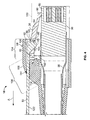
- Figure 4 is a cross sectional view of the electrical connector shown in Figure 1 with a latch of the electrical connector in a latched position.
- Figure 5 is a cross sectional view of the electrical connector with the latch in an unlatched position.
- FIG 1 is a perspective view of an exemplary electrical connector 10 formed in accordance with an exemplary embodiment.
- the electrical connector 10 represents a plug connector that may be mated with a mating connector 12, represented by the receptacle connector in Figure 1 .
- the electrical connector 10 and the mating connector 12 are modular connectors, such as the types of electrical connectors used for connecting telecommunications equipment or computer networking equipment.
- the electrical connector 10 and the mating connector 12 are eight pin, eight conductor (8P8C) modular connectors having signal pairs, however the subject matter described herein also has applicability to other connectors having fewer or greater numbers of pins, conductors and/or signal pairs.
- 8P8C eight pin, eight conductor
- the mating connector 12 includes a housing 14 having multiple communication ports 16 opening to receptacles 18 that receive respective ones of the electrical connectors 10.
- the mating connector 12 also includes contact support members 20 that are arranged within respective ones of the receptacles 18.
- Each of the contact support members 20 includes a plurality of mating contacts 22 arranged along a mating interface for mating with corresponding contacts 24 of the electrical connector 10.
- the mating contacts 22 and the contacts 24 are arranged in similar patterns for mating engagement.
- the mating contacts 22 and contacts 24 are arranged, or grouped, as differential signal pairs.
- the electrical connector 10 includes a latch 26 on an exterior surface thereof for securing the electrical connector 10 within the receptacle 18.
- a boot 30 is provided to surround the electrical connector 10, including the latch 26.
- a tether 32 is provided for actuating the latch 26.
- the housing 14 is mounted to a substrate 28.
- the substrate 28 may represent a circuit board and the electrical connector may be mechanically and electrically connected to the circuit board for sending and receiving signals.
- the substrate 28 and mating connector 12 may be mounted within an electrical device or apparatus having a communications port through which the device may communicate with other externally networked devices.
- the mating connector 12 may be wall mounted or panel mounted for connection with the electrical connectors 10.
- the mating connector 12 may include only a single receptacle 18 and corresponding contact support member 20 for mating with a single electrical connector 10.
- the mating connector 12, or more particularly, the contacts 22, may be terminated to an end of a cable (not shown).
- FIG 2 illustrates a portion of the electrical connector 10, with the boot 30 (shown in Figure 1 ) and the tether 32 (shown in Figure 1 ) removed for clarity.
- the electrical connector 10 is coupled to an end of a cable 34.
- the electrical connector 10 includes a housing 36 and a ferrule 38 extending from the housing 36.
- the ferrule 38 is coupled to the housing 36 using a latching mechanism 40, or other type of fastener.
- the ferrule 38 surrounds the cable 34 and the individual wires (not shown) that form the cable 34.
- the ferrule 38 is securely coupled to the cable 34 to resist removal of the cable 34 from the electrical connector 10.
- a portion of the ferrule 38 may be crimped, or otherwise secured to, the cable 34.
- the ferrule 38 may be fabricated from a metal material and the ferrule 38 may provide shielding around the end of the cable 34 and the wires of the cable 34.
- the housing 36 has a cavity 42 defined by outer walls 44 that define a perimeter of the housing 36.
- the outer walls 44 extend between a mating end 46 and a cable end 48 of the housing 36.
- the outer walls 44 include a top wall 50, a bottom wall 52 and opposed side walls 54, 56.
- the latch 26 extends from the top wall 50.
- the housing 36 is fabricated from a non-conductive material, such as plastic, and is molded into form.
- the latch 26 may be integrally formed with the housing 36, however the latch 26 may be separately provided in alternative embodiments.
- the contacts 24 are provided within the cavity 42 for interfacing with the mating contacts 22 (shown in Figure 1 ) of the mating connector 12 (shown in Figure 1 ).
- the contacts 24 may be terminated to individual wires (not shown) of the cable 34 proximate the cable end 48 of the housing 36.
- the latch 26 extends between a fixed end 60 and a distal end 62.
- the latch 26 is cantilevered such that the distal end 62 is elevated from the top wall 50 of the housing 36.
- the latch 26 is movable between a latched position, such as the position shown in Figure 2 , and an unlatched position. In the unlatched position, the latch 26 is positioned relatively closer to the top wall 50 of the housing 36. For example, when the latch 26 is depressed downward, the latch 26 rotates about the fixed end 60 generally toward the top wall 50.
- the latch 26 includes a latching surface 64 that is configured to engage a corresponding latching surface (not shown) of the mating connector 12 to securely couple the electrical connector 10 to the mating connector 12. For example, that latching surface 64 of the latch 26 engages the latching surface of the mating connector 10 when the latch 26 is in the latched position. Removal of the electrical connector 10 is restricted by the engagement of the latching surface 64 with the latching surface of the mating connector 12.
- the latch 26 includes a window 66 proximate the distal end 62.
- the window 66 is rectangular and is defined by a forward edge 68, a rearward edge 70 and side edges 72.
- the window 66 may have a different shape.
- the edges 68-72 may extend generally perpendicularly from a top surface 74 of the latch 26.
- the window 66 extends entirely through the latch 26 from the top surface 74 to a bottom surface 76.
- the window 66 extends only partially through the latch 26 from either the top surface 74 or the bottom surface 76.
- Figure 3 is a front perspective view of the electrical connector 10 with the boot 30 and tether 32 provided.
- the boot 30 includes a strain relief portion 80 that surrounds, and is coupled to, the cable 34.
- the strain relief portion 80 is provided at a rear of the boot 30.
- the boot 30 also includes a connector portion 82 that surrounds at least a portion of the electrical connector 10.
- the connector portion 82 may surround at least part of the ferrule 38 and/or at least part of the housing 36.
- the connector portion 82 is provided at a front of the boot 30.
- the connector portion 82 may be securely coupled to the electrical connector 10, such as by a friction fit, a mechanical fastener, an adhesive, and the like.
- the connector portion 82 includes a hood portion 84.
- the hood portion 84 defines a cavity 86 that has an opening 88 providing access thereto.
- the hood portion 84 is provided at the front of the boot 30 and is provided on top of the housing 36 and/or ferrule 38.
- the latch 26 extends at least partially into the cavity 86 defined by the hood portion 84.
- the hood portion 84 protects the latch 26.
- the boot 30, and particularly the hood portion 84 may be manufactured from a synthetic material, such as a plastic material or a rubber material.
- the hood portion 84 may be flexible to allow manual actuation of the latch 26 by pressing on the hood portion 84 in the vicinity of the latch 26.
- the tether 32 is coupled to the latch 26 inside the hood portion 84.
- the tether 32 is configured to be pulled in a pulling direction, shown by arrow A in Figure 3 , to actuate the latch 26.
- the tether 32 is movable between a released position and an actuated position. When sufficient force is applied to the tether 32 in the pulling direction, the tether 32 is moved from the released position to the actuated position. When the tether 32 is released, the tether 32 is movable back to the released position in a direction generally opposite to the pulling direction.
- the tether 32 may be automatically returned to the released position due to resiliency of the latch, such that the operator is not required to manually move or push the tether 32 back to the released position.
- the tether 32 may be arranged such that the operator is required to move the tether 32 back to the released position.
- the tether 32 includes a body 90 extending between a mating end 92 and a pulling end 94.
- the tether 32 is fabricated from a synthetic material, such as a plastic material or a rubber material.
- the tether 32 may be flexible such that the tether 32 may be manipulated by a user during operation.
- the mating end 92 engages the latch 26 and, as described in further detail below, actuates the latch 26 during operation.
- the tether 32 extends outward from a rear of the hood portion 84 to the pulling end 94.
- the pulling end 94 is positioned a distance 96 from the mating end 92 and the associated latch 26.
- the pulling end 94 is accessible to a user to grasp and pull generally in the pulling direction, which is generally away from the mating interface of the electrical connector 10.
- a plurality of ribs 98 are provided at the pulling end 94 to provide additional grip when the user is pulling the tether 32.
- Assembly of the electrical connector 10, and more particularly, positioning of the tether 32 within the cavity 86 is accomplished in an exemplary embodiment, by loading the tether 32 through the opening 88 in the front of the hood portion 84.
- the pulling end 94 of the tether 32 is loaded into the cavity 86 through the hood portion 84 until the mating end 92 of the tether 32 engages the latch 26.
- a portion of the tether 32 is received in the window 66.
- the tether 32 may be mounted to the electrical connector 10 as a final assembly stage.
- the tether 32 may be mounted to the electrical connector 10 in the field by a technician immediately prior to coupling the electrical connector 10 with the mating connector 12.
- the tether 32 may be an optional feature and the electrical connector 10 may be coupled to the mating connector 12, and un-coupled from the mating connector 12, without the tether 32. Additionally, the tether 32 is mated with the latch 26 in a simple fashion and without the need for additionally interconnecting components that may be lost, damaged or difficult to install.
- Figure 4 is a cross sectional view of the electrical connector 10 with the latch 26 of the electrical connector 10 in a latched position and the tether 32 in a released position.
- the latching surface 64 engages a corresponding latching surface 100, which is shown in phantom in Figure 4 , of the mating connector (shown in Figure 1 ).
- the distal end 62 of the latch 26 is elevated from the top wall 50 by a distance 102.
- the hood portion 84 extends from the top of the housing 36 and the ferrule 38.
- the hood portion 84 is defined by a forward section 104 and a rear section 106.
- the forward section 104 defines the cavity 86 and extends generally parallel to the top of the housing 36 and the ferrule 38.
- the rear section 106 has a generally curved outer surface 108.
- the rear section 106 may extend from the outer surface 108 to a front surface 110 and a bottom surface 112.
- the front surface 110 defines a back of the cavity 86.
- the bottom surface 112 may engage or rest upon the top of the ferrule 38.
- a channel or slot 114 is formed through the rear section 106 between the outer surface 108 and the cavity 86.
- the slot 114 is sized to receive the tether 32, which extends from the cavity 86, through the slot 114 and rearward from the rear section 106.
- the tether 32 includes an embossment 120 extending generally perpendicularly from a bottom 122 of the tether 32.
- the embossment 120 is provided proximate the mating end 92.
- the embossment 120 is provided at the mating end 92.
- the embossment 120 includes a ramp surface 124 that extends from a base 126 to a tip 128.
- the ramp surface 124 is generally rearward facing.
- the embossment 120 is received within the window 66 of the latch 26.
- the ramp surface 124 is generally facing, and may engage the rearward edge 70 of the window 66.
- the ramp surface 124 engages the rearward edge 70 and the rearward edge 70 rides down the ramp surface 124 generally from the base 126 toward the tip 128.
- the latch 26 is moved toward the unlatched position (shown in Figure 5 ).
- the distal end 62 is rotated about the fixed end 60 generally toward the housing 36 and the ferrule 38, such as in an unlatching direction shown by arrow B in Figure 4 .
- Figure 5 is a cross sectional view of the electrical connector 10 with the latch 26 in an unlatched position and the tether 32 in an actuated position.
- the latching surface 64 In the unlatched position, the latching surface 64 is positioned below the latching surface 100 of the mating connector 12 (shown in Figure 1 ). As such, the latching surface 100 no longer engages or blocks the latching surface 64.
- the electrical connector 10 may be disengaged and removed from the mating connector 12.
- the tether 32 is utilized to transfer the latch 26 from the latched position (shown in Figure 4 ) to the unlatched position.
- the latch 26 may be moved to the unlatched position independent of actuation by the tether 32.
- pressing downward on the forward section 104 of the hood portion 84 may deflect the latch 26 without moving the tether 32 to the actuated position.
- the latch 26 includes a ramp 130 forward of the latching surface 64. During mating of the electrical connector 10 with the mating connector 12, the ramp 130 engages the mating connector 12 and deflects the latch 26 to the unlatched position without the need to pull the tether 32 to the actuated position.
- the ramp surface 124 engages the latch 26 and forces the latch 26 downward to the unlatched position.
- the front surface 110 of the rear section 106 defines a shoulder that acts as a travel limit for the tether 32.
- a portion of the ramp surface 124 engages the front surface 110. Further movement of the tether 32 in the pulling direction is restricted by the front surface 110.
- the latch 26 when the tether 32 is released, the latch 26 has adequate resiliency and/or flexibility to return to the latched position.
- the material characteristics and/or the thickness of the latch 26 may force the latch 26 to tend to return to the normal or latched position.
- the rearward edge 70 engages the ramp surface 124 and rides up the ramp surface 124 generally toward the base 126 forcing the tether 32 to return to the released position. In this manner, the tether 32 is automatically returned to the released position without requiring the operator to move or push the tether 32 back to the released position.
Landscapes
- Details Of Connecting Devices For Male And Female Coupling (AREA)
Abstract
Description
- The invention relates to an electrical connector having a pull tether for releasing a latch.
- In the electronics industry, and in particular the telecommunications industry, there is an increasing trend towards smaller electrical connectors, particularly cable mounted plugs. The industries are also tending to use more densely packaged connectors and connector systems. For example, in switching networks, such as patch panels, the connectors are positioned in multiple rows in tightly spaced areas. Other examples include computers having multiple ports arranged on a panel. The ports are typically arranged in a plurality of rows that are spaced close to one another.
- Because the rows are positioned in such close proximity, difficulties arise for a technician to access the latching mechanism that is used to secure the connector to the panel. The spacing between the connectors is simply too small to accommodate the technician's fingers to release the latching mechanism. Additionally, the latching mechanism is typically positioned at the mating interface of the connector with the panel. The cables and/or the connectors tend to block access to the latching mechanism, particularly when the connectors are arranged in multiple rows. Damage may be caused to the latching mechanism or the connector itself by the technician when trying to reach the latching mechanism. Special tools have been developed to reach into the tight spaces to release the latching mechanism such that the electrical connector may be removed. However, such tools are cumbersome to use.
- There is a need for an electrical connector that can be unlatched in an efficient manner.
- This problem is solved by an electrical connector according to claim 1.
- According to the invention, an electrical connector comprises a housing having a plurality of contacts defining a mating interface for a mating connector. A latch extends from the housing and includes a window. The latch is configured to securely couple the housing to the mating connector, and the latch is depressible to an unlatched position to release the housing from the mating connector. A tether is mated with the latch and is movable between a released position and an actuated position. The tether has an embossment that extends into the window when the tether is in the released position. The embossment engages an edge of the window and depresses the latch to the unlatched position when the tether is moved to the actuated position.
- The invention will now be described by way of example with reference to the accompanying drawings wherein:
-
Figure 1 is a perspective view of an exemplary electrical connector formed in accordance with an exemplary embodiment. -
Figure 2 is a front perspective view of the electrical connector shown inFigure 1 with a boot and tether removed. -
Figure 3 is a front perspective view of the electrical connector with the boot and tether provided. -
Figure 4 is a cross sectional view of the electrical connector shown inFigure 1 with a latch of the electrical connector in a latched position. -
Figure 5 is a cross sectional view of the electrical connector with the latch in an unlatched position. -
Figure 1 is a perspective view of an exemplaryelectrical connector 10 formed in accordance with an exemplary embodiment. Theelectrical connector 10 represents a plug connector that may be mated with amating connector 12, represented by the receptacle connector inFigure 1 . Theelectrical connector 10 and themating connector 12 are modular connectors, such as the types of electrical connectors used for connecting telecommunications equipment or computer networking equipment. In the illustrated embodiment, theelectrical connector 10 and themating connector 12 are eight pin, eight conductor (8P8C) modular connectors having signal pairs, however the subject matter described herein also has applicability to other connectors having fewer or greater numbers of pins, conductors and/or signal pairs. - In an exemplary embodiment, the
mating connector 12 includes ahousing 14 havingmultiple communication ports 16 opening toreceptacles 18 that receive respective ones of theelectrical connectors 10. Themating connector 12 also includescontact support members 20 that are arranged within respective ones of thereceptacles 18. Each of thecontact support members 20 includes a plurality ofmating contacts 22 arranged along a mating interface for mating withcorresponding contacts 24 of theelectrical connector 10. For example, themating contacts 22 and thecontacts 24 are arranged in similar patterns for mating engagement. Optionally, themating contacts 22 andcontacts 24 are arranged, or grouped, as differential signal pairs. In an exemplary embodiment, theelectrical connector 10 includes alatch 26 on an exterior surface thereof for securing theelectrical connector 10 within thereceptacle 18. Aboot 30 is provided to surround theelectrical connector 10, including thelatch 26. Atether 32 is provided for actuating thelatch 26. - The
housing 14 is mounted to asubstrate 28. Optionally, thesubstrate 28 may represent a circuit board and the electrical connector may be mechanically and electrically connected to the circuit board for sending and receiving signals. Thesubstrate 28 andmating connector 12 may be mounted within an electrical device or apparatus having a communications port through which the device may communicate with other externally networked devices. Alternatively, themating connector 12 may be wall mounted or panel mounted for connection with theelectrical connectors 10. In some embodiments, themating connector 12 may include only asingle receptacle 18 and correspondingcontact support member 20 for mating with a singleelectrical connector 10. Additionally, in some embodiments, rather than sending and receiving the signals via a circuit board, themating connector 12, or more particularly, thecontacts 22, may be terminated to an end of a cable (not shown). -
Figure 2 illustrates a portion of theelectrical connector 10, with the boot 30 (shown inFigure 1 ) and the tether 32 (shown inFigure 1 ) removed for clarity. Theelectrical connector 10 is coupled to an end of acable 34. Theelectrical connector 10 includes ahousing 36 and aferrule 38 extending from thehousing 36. Theferrule 38 is coupled to thehousing 36 using alatching mechanism 40, or other type of fastener. Theferrule 38 surrounds thecable 34 and the individual wires (not shown) that form thecable 34. Theferrule 38 is securely coupled to thecable 34 to resist removal of thecable 34 from theelectrical connector 10. For example, a portion of theferrule 38 may be crimped, or otherwise secured to, thecable 34. Optionally, theferrule 38 may be fabricated from a metal material and theferrule 38 may provide shielding around the end of thecable 34 and the wires of thecable 34. - The
housing 36 has acavity 42 defined byouter walls 44 that define a perimeter of thehousing 36. Theouter walls 44 extend between amating end 46 and acable end 48 of thehousing 36. In an exemplary embodiment, theouter walls 44 include atop wall 50, abottom wall 52 and opposedside walls latch 26 extends from thetop wall 50. Other configurations are possible in alternative embodiments. In one embodiment, thehousing 36 is fabricated from a non-conductive material, such as plastic, and is molded into form. Optionally, thelatch 26 may be integrally formed with thehousing 36, however thelatch 26 may be separately provided in alternative embodiments. - The
contacts 24 are provided within thecavity 42 for interfacing with the mating contacts 22 (shown inFigure 1 ) of the mating connector 12 (shown inFigure 1 ). Thecontacts 24 may be terminated to individual wires (not shown) of thecable 34 proximate thecable end 48 of thehousing 36. - The
latch 26 extends between afixed end 60 and adistal end 62. Thelatch 26 is cantilevered such that thedistal end 62 is elevated from thetop wall 50 of thehousing 36. Thelatch 26 is movable between a latched position, such as the position shown inFigure 2 , and an unlatched position. In the unlatched position, thelatch 26 is positioned relatively closer to thetop wall 50 of thehousing 36. For example, when thelatch 26 is depressed downward, thelatch 26 rotates about thefixed end 60 generally toward thetop wall 50. - The
latch 26 includes a latchingsurface 64 that is configured to engage a corresponding latching surface (not shown) of themating connector 12 to securely couple theelectrical connector 10 to themating connector 12. For example, that latchingsurface 64 of thelatch 26 engages the latching surface of themating connector 10 when thelatch 26 is in the latched position. Removal of theelectrical connector 10 is restricted by the engagement of the latchingsurface 64 with the latching surface of themating connector 12. - The
latch 26 includes awindow 66 proximate thedistal end 62. In an exemplary embodiment, thewindow 66 is rectangular and is defined by aforward edge 68, arearward edge 70 and side edges 72. Alternatively, thewindow 66 may have a different shape. Optionally, the edges 68-72 may extend generally perpendicularly from atop surface 74 of thelatch 26. In an exemplary embodiment, thewindow 66 extends entirely through thelatch 26 from thetop surface 74 to abottom surface 76. Alternatively, thewindow 66 extends only partially through thelatch 26 from either thetop surface 74 or thebottom surface 76. -
Figure 3 is a front perspective view of theelectrical connector 10 with theboot 30 andtether 32 provided. Theboot 30 includes astrain relief portion 80 that surrounds, and is coupled to, thecable 34. Thestrain relief portion 80 is provided at a rear of theboot 30. Theboot 30 also includes aconnector portion 82 that surrounds at least a portion of theelectrical connector 10. For example, theconnector portion 82 may surround at least part of theferrule 38 and/or at least part of thehousing 36. Theconnector portion 82 is provided at a front of theboot 30. Optionally, theconnector portion 82 may be securely coupled to theelectrical connector 10, such as by a friction fit, a mechanical fastener, an adhesive, and the like. - In an exemplary embodiment, the
connector portion 82 includes ahood portion 84. Thehood portion 84 defines acavity 86 that has anopening 88 providing access thereto. In the illustrated embodiment, thehood portion 84 is provided at the front of theboot 30 and is provided on top of thehousing 36 and/orferrule 38. Thelatch 26 extends at least partially into thecavity 86 defined by thehood portion 84. As such, thehood portion 84 protects thelatch 26. Optionally, theboot 30, and particularly thehood portion 84, may be manufactured from a synthetic material, such as a plastic material or a rubber material. Thehood portion 84 may be flexible to allow manual actuation of thelatch 26 by pressing on thehood portion 84 in the vicinity of thelatch 26. - The
tether 32 is coupled to thelatch 26 inside thehood portion 84. Thetether 32 is configured to be pulled in a pulling direction, shown by arrow A inFigure 3 , to actuate thelatch 26. Thetether 32 is movable between a released position and an actuated position. When sufficient force is applied to thetether 32 in the pulling direction, thetether 32 is moved from the released position to the actuated position. When thetether 32 is released, thetether 32 is movable back to the released position in a direction generally opposite to the pulling direction. Optionally, thetether 32 may be automatically returned to the released position due to resiliency of the latch, such that the operator is not required to manually move or push thetether 32 back to the released position. In other embodiments, thetether 32 may be arranged such that the operator is required to move thetether 32 back to the released position. - The
tether 32 includes abody 90 extending between amating end 92 and a pullingend 94. In an exemplary embodiment, thetether 32 is fabricated from a synthetic material, such as a plastic material or a rubber material. Thetether 32 may be flexible such that thetether 32 may be manipulated by a user during operation. Themating end 92 engages thelatch 26 and, as described in further detail below, actuates thelatch 26 during operation. Thetether 32 extends outward from a rear of thehood portion 84 to the pullingend 94. The pullingend 94 is positioned adistance 96 from themating end 92 and the associatedlatch 26. The pullingend 94 is accessible to a user to grasp and pull generally in the pulling direction, which is generally away from the mating interface of theelectrical connector 10. In an exemplary embodiment, a plurality ofribs 98 are provided at the pullingend 94 to provide additional grip when the user is pulling thetether 32. - Assembly of the
electrical connector 10, and more particularly, positioning of thetether 32 within thecavity 86, is accomplished in an exemplary embodiment, by loading thetether 32 through theopening 88 in the front of thehood portion 84. For example, the pullingend 94 of thetether 32 is loaded into thecavity 86 through thehood portion 84 until themating end 92 of thetether 32 engages thelatch 26. In an exemplary embodiment, a portion of thetether 32 is received in thewindow 66. Thetether 32 may be mounted to theelectrical connector 10 as a final assembly stage. In an exemplary embodiment, thetether 32 may be mounted to theelectrical connector 10 in the field by a technician immediately prior to coupling theelectrical connector 10 with themating connector 12. As such, thetether 32 may be an optional feature and theelectrical connector 10 may be coupled to themating connector 12, and un-coupled from themating connector 12, without thetether 32. Additionally, thetether 32 is mated with thelatch 26 in a simple fashion and without the need for additionally interconnecting components that may be lost, damaged or difficult to install. -
Figure 4 is a cross sectional view of theelectrical connector 10 with thelatch 26 of theelectrical connector 10 in a latched position and thetether 32 in a released position. In the latched position, the latchingsurface 64 engages acorresponding latching surface 100, which is shown in phantom inFigure 4 , of the mating connector (shown inFigure 1 ). In the latched position, thedistal end 62 of thelatch 26 is elevated from thetop wall 50 by adistance 102. - The
hood portion 84 extends from the top of thehousing 36 and theferrule 38. Thehood portion 84 is defined by aforward section 104 and arear section 106. Theforward section 104 defines thecavity 86 and extends generally parallel to the top of thehousing 36 and theferrule 38. Therear section 106 has a generally curvedouter surface 108. Optionally, therear section 106 may extend from theouter surface 108 to afront surface 110 and abottom surface 112. Thefront surface 110 defines a back of thecavity 86. Thebottom surface 112 may engage or rest upon the top of theferrule 38. A channel orslot 114 is formed through therear section 106 between theouter surface 108 and thecavity 86. Theslot 114 is sized to receive thetether 32, which extends from thecavity 86, through theslot 114 and rearward from therear section 106. - The
tether 32 includes an embossment 120 extending generally perpendicularly from abottom 122 of thetether 32. The embossment 120 is provided proximate themating end 92. Optionally, the embossment 120 is provided at themating end 92. The embossment 120 includes aramp surface 124 that extends from a base 126 to atip 128. Theramp surface 124 is generally rearward facing. The embossment 120 is received within thewindow 66 of thelatch 26. Theramp surface 124 is generally facing, and may engage therearward edge 70 of thewindow 66. In operation, when thetether 32 is pulled in the pulling direction, shown by arrow A, theramp surface 124 engages therearward edge 70 and therearward edge 70 rides down theramp surface 124 generally from the base 126 toward thetip 128. As thetether 32 is pulled in the pulling direction, thelatch 26 is moved toward the unlatched position (shown inFigure 5 ). For example, thedistal end 62 is rotated about thefixed end 60 generally toward thehousing 36 and theferrule 38, such as in an unlatching direction shown by arrow B inFigure 4 . -
Figure 5 is a cross sectional view of theelectrical connector 10 with thelatch 26 in an unlatched position and thetether 32 in an actuated position. In the unlatched position, the latchingsurface 64 is positioned below the latchingsurface 100 of the mating connector 12 (shown inFigure 1 ). As such, the latchingsurface 100 no longer engages or blocks the latchingsurface 64. Theelectrical connector 10 may be disengaged and removed from themating connector 12. - As described above, in an exemplary embodiment, the
tether 32 is utilized to transfer thelatch 26 from the latched position (shown inFigure 4 ) to the unlatched position. However, thelatch 26 may be moved to the unlatched position independent of actuation by thetether 32. For example, pressing downward on theforward section 104 of thehood portion 84 may deflect thelatch 26 without moving thetether 32 to the actuated position. Additionally, thelatch 26 includes aramp 130 forward of the latchingsurface 64. During mating of theelectrical connector 10 with themating connector 12, theramp 130 engages themating connector 12 and deflects thelatch 26 to the unlatched position without the need to pull thetether 32 to the actuated position. - In operation, when the
tether 32 is pulled to the actuated position, theramp surface 124 engages thelatch 26 and forces thelatch 26 downward to the unlatched position. In an exemplary embodiment, thefront surface 110 of therear section 106 defines a shoulder that acts as a travel limit for thetether 32. For example, when thetether 32 is pulled to the actuated position, a portion of theramp surface 124 engages thefront surface 110. Further movement of thetether 32 in the pulling direction is restricted by thefront surface 110. - In operation, in an exemplary embodiment, when the
tether 32 is released, thelatch 26 has adequate resiliency and/or flexibility to return to the latched position. For example, the material characteristics and/or the thickness of thelatch 26 may force thelatch 26 to tend to return to the normal or latched position. As thelatch 26 returns to the latched position, therearward edge 70 engages theramp surface 124 and rides up theramp surface 124 generally toward the base 126 forcing thetether 32 to return to the released position. In this manner, thetether 32 is automatically returned to the released position without requiring the operator to move or push thetether 32 back to the released position.
Claims (6)
- An electrical connector (10) characterized by:a housing (36) having a plurality of contacts (24) defining a mating interface for a mating connector (12);a latch (26) extending from the housing (36), the latch (26) having a window (66), the latch (26) being configured to securely couple the housing (36) to the mating connector (12), the latch (26) being depressible to an unlatched position to release the housing (36) from the mating connector (12);a tether (32) mated with the latch (26), the tether (32) being movable between a released position and an actuated position, the tether (32) having an embossment (120) that extends into the window (66) when the tether (32) is in the released position, and the embossment (120) engages an edge (70) of the window (66) and depresses the latch (26) to the unlatched position when the tether (32) is moved to the actuated position.
- The electrical connector (10) of claim 1, wherein the embossment (120) has a ramp surface (124) extending from a base (126) to a tip (128), and the latch (26) rides along the ramp surface (124) toward the tip (128) as the tether (32) is moved to the actuated position.
- The electrical connector (10) of claim 1 or 2, wherein the embossment (120) has a ramp surface (124), and the latch (26) has adequate resiliency to force the tether (32) to the released position by engaging the ramp surface (124) as the latch (26) returns to the latched position.
- The electrical connector (10) of any preceding claim, further comprising a boot (30) surrounding a portion of the housing (36), the boot (30) includes a hood portion (84), and the tether (32) engages the latch (26) inside the hood portion (84).
- The electrical connector (10) of any preceding claim, wherein the tether (32) extends through a slot (114) in a rear section (106) of the hood portion (84).
- The electrical connector (10) of claim 5, wherein the hood portion (84) includes a front opening (88), the tether (32) is loaded into the hood portion (84) through the front opening (88) and extends from the rear section (106) of the hood portion (84).
Applications Claiming Priority (1)
| Application Number | Priority Date | Filing Date | Title |
|---|---|---|---|
| US12/113,071 US7651361B2 (en) | 2008-04-30 | 2008-04-30 | Electrical connector having pull tether for latch release |
Publications (3)
| Publication Number | Publication Date |
|---|---|
| EP2113968A2 true EP2113968A2 (en) | 2009-11-04 |
| EP2113968A3 EP2113968A3 (en) | 2011-07-20 |
| EP2113968B1 EP2113968B1 (en) | 2014-04-30 |
Family
ID=40673415
Family Applications (1)
| Application Number | Title | Priority Date | Filing Date |
|---|---|---|---|
| EP09159165.1A Active EP2113968B1 (en) | 2008-04-30 | 2009-04-30 | Electrical connector having pull tether for latch release |
Country Status (3)
| Country | Link |
|---|---|
| US (1) | US7651361B2 (en) |
| EP (1) | EP2113968B1 (en) |
| CN (1) | CN101572363B (en) |
Cited By (1)
| Publication number | Priority date | Publication date | Assignee | Title |
|---|---|---|---|---|
| CN107408782A (en) * | 2015-02-10 | 2017-11-28 | 莫列斯有限公司 | Wire and cable connector |
Families Citing this family (59)
| Publication number | Priority date | Publication date | Assignee | Title |
|---|---|---|---|---|
| DE202010003117U1 (en) * | 2010-03-03 | 2010-05-27 | Wago Verwaltungsgesellschaft Mbh | Connector device with an unlocking device |
| CN102201631A (en) * | 2010-03-26 | 2011-09-28 | 富士康(昆山)电脑接插件有限公司 | Electric connector component |
| CN201708379U (en) * | 2010-04-07 | 2011-01-12 | 富士康(昆山)电脑接插件有限公司 | Cable Connector Assembly |
| US8025514B1 (en) | 2010-04-23 | 2011-09-27 | Leviton Manufacturing Co., Inc. | Shroud to prevent manipulation of a release mechanism of a plug |
| US8038456B1 (en) | 2010-04-23 | 2011-10-18 | Leviton Manufacturing Co., Inc | Tamper prevention system having a shroud to partially cover a release mechanism |
| US8585426B2 (en) | 2010-07-27 | 2013-11-19 | Fci Americas Technology Llc | Electrical connector including latch assembly |
| US8475197B2 (en) | 2010-07-27 | 2013-07-02 | Fci Americas Technology Llc | Electrical connector including latch assembly |
| CN102544903A (en) * | 2010-12-28 | 2012-07-04 | 鸿富锦精密工业(深圳)有限公司 | Auxiliary device for pulling out crystal head and crystal head combination |
| JP2012150913A (en) * | 2011-01-17 | 2012-08-09 | Yazaki Corp | Electric wire holder, and connecting method of electric wire holder |
| ES2395358B1 (en) | 2011-02-08 | 2014-04-25 | Tyco Electronics Corporation | SINGLE ACTION CONNECTOR |
| ES2402632B1 (en) | 2011-02-08 | 2014-05-14 | Tyco Electronics Raychem Bvba | RELEASE TONGUE FOR AN ELECTRICAL CONNECTOR AND ELECTRICAL CONNECTOR THAT INCLUDES SUCH RELEASE TONGUE |
| WO2012177486A2 (en) | 2011-06-21 | 2012-12-27 | Adc Telecommunications, Inc. | Connector with cable retention feature and patch cord having the same |
| US8684763B2 (en) | 2011-06-21 | 2014-04-01 | Adc Telecommunications, Inc. | Connector with slideable retention feature and patch cord having the same |
| CN103025097A (en) * | 2011-09-20 | 2013-04-03 | 鸿富锦精密工业(深圳)有限公司 | Electronic device |
| EP2748898B1 (en) * | 2011-10-05 | 2017-07-05 | Senko Advanced Components, Inc. | Latching connector with remote release |
| US8556645B2 (en) * | 2012-01-23 | 2013-10-15 | Commscope, Inc. Of North Carolina | Delatching connector including extension member |
| US8747141B2 (en) * | 2012-01-23 | 2014-06-10 | Commscope, Inc. Of North Carolina | Delatching connector including extension member |
| CN103257407B (en) | 2012-02-20 | 2015-11-25 | 泰科电子(上海)有限公司 | Connector and connector assembly |
| CN103311736A (en) * | 2012-03-07 | 2013-09-18 | 鸿富锦精密工业(深圳)有限公司 | Connector pulling-out assisting device |
| JP6006575B2 (en) * | 2012-07-31 | 2016-10-12 | タイコエレクトロニクスジャパン合同会社 | connector |
| US9246262B2 (en) | 2012-08-06 | 2016-01-26 | Fci Americas Technology Llc | Electrical connector including latch assembly with pull tab |
| CN103178400B (en) * | 2013-03-01 | 2015-07-08 | 中航光电科技股份有限公司 | Connector capable of being unlocked by aid of pull ring and pull ring mounting structure of connector |
| US8979569B2 (en) * | 2013-03-15 | 2015-03-17 | Ortronics, Inc. | Modular connectors and associated systems and methods |
| CN104112943A (en) * | 2013-04-17 | 2014-10-22 | 鸿富锦精密电子(天津)有限公司 | Assisting connector plugging and pulling device |
| CN103337738B (en) * | 2013-06-06 | 2015-09-30 | 苏州华旃航天电器有限公司 | Pull the pin connector of unblock |
| US9810859B2 (en) * | 2013-08-21 | 2017-11-07 | Mertek Industries, Llc | Traceable networking cables with remote-released connectors |
| JP6153445B2 (en) * | 2013-10-11 | 2017-06-28 | 日置電機株式会社 | Connector unit |
| US9325138B2 (en) | 2013-12-02 | 2016-04-26 | International Business Machines Corporation | Cable remover |
| DE102014100059B4 (en) * | 2014-01-06 | 2016-07-21 | Gb Gmbh - Bss | Assembly tool for releasing a plug |
| EP3907541B1 (en) | 2014-01-13 | 2023-12-27 | CommScope Telecommunications (Shanghai) Co. Ltd. | Fiber optic connector |
| US10014627B2 (en) * | 2014-08-20 | 2018-07-03 | Volex Plc | Electrical connector with unlocking sleeve |
| US9599778B2 (en) * | 2014-10-22 | 2017-03-21 | Senko Advanced Components, Inc. | Latching connector with remote release |
| EP3203591B1 (en) * | 2016-02-05 | 2020-10-28 | Rosenberger Hochfrequenztechnik GmbH & Co. KG | Connector |
| US9853397B1 (en) | 2016-09-16 | 2017-12-26 | Te Connectivity Corporation | Pluggable module having pull tether for latch release |
| DE102016221063B4 (en) * | 2016-10-26 | 2021-09-16 | BSH Hausgeräte GmbH | Household appliance with at least one plug for an electrical connection |
| US10079451B2 (en) | 2016-11-14 | 2018-09-18 | Te Connectivity Corporation | Pull tab device for a latch of a pluggable module |
| CN110249248B (en) | 2017-01-30 | 2021-07-27 | 扇港元器件股份有限公司 | Optical connectors with reversible polarity |
| US10444444B2 (en) * | 2017-01-30 | 2019-10-15 | Senko Advanced Components, Inc. | Remote release tab connector assembly |
| US11333836B2 (en) | 2017-01-30 | 2022-05-17 | Senko Advanced Components, Inc. | Adapter for optical connectors |
| US10725248B2 (en) | 2017-01-30 | 2020-07-28 | Senko Advanced Components, Inc. | Fiber optic receptacle with integrated device therein incorporating a behind-the-wall fiber optic receptacle |
| US10367299B2 (en) * | 2017-03-29 | 2019-07-30 | Foxconn Interconnect Technology Limited | Plug connector assembly with an unlocking apparatus for unlocking a latch |
| US10020614B1 (en) * | 2017-04-14 | 2018-07-10 | Te Connectivity Corporation | Pluggable module having a latch |
| US11215767B2 (en) | 2017-06-07 | 2022-01-04 | Commscope Technologies Llc | Fiber optic adapter and cassette |
| CN107132623B (en) * | 2017-07-10 | 2023-08-08 | 广东亿源通科技股份有限公司 | Optical fiber connector |
| EP3682277B1 (en) | 2017-09-15 | 2025-02-19 | Commscope Technologies LLC | Fiber optic connector with boot-integrated release |
| CN111033339B (en) | 2018-03-28 | 2023-09-19 | 扇港元器件股份有限公司 | The optical fiber connector |
| US11689247B2 (en) | 2019-01-16 | 2023-06-27 | Mertek Industries, Llc | Patch cord including wireless components |
| US10547142B1 (en) * | 2019-03-14 | 2020-01-28 | Te Connectivity Corporation | Latch assembly for a plug connector |
| JP7313185B2 (en) * | 2019-04-30 | 2023-07-24 | タイコエレクトロニクスジャパン合同会社 | connector housing |
| WO2021067241A1 (en) | 2019-09-30 | 2021-04-08 | Mertek Industries, Llc | Patch panel traceable networking system |
| CN210864140U (en) | 2019-12-17 | 2020-06-26 | 新确精密科技(深圳)有限公司 | A fiber optic box |
| CN111224260A (en) | 2020-01-15 | 2020-06-02 | 东莞立讯技术有限公司 | Socket connector and connector combination |
| CN111180966B (en) | 2020-01-15 | 2021-10-22 | 东莞立讯技术有限公司 | Plug connector |
| WO2021243076A1 (en) | 2020-05-29 | 2021-12-02 | Commscope Technologies Llc | Telecommunications connector with latch release mechanism |
| TWI767630B (en) * | 2021-03-24 | 2022-06-11 | 宏正自動科技股份有限公司 | Eletrical connector |
| US12541063B2 (en) * | 2021-04-02 | 2026-02-03 | Us Conec Ltd. | Ferrule holder for miniature mt ferrule and adapter interface for mating with fiber optic connectors |
| US12523821B2 (en) | 2021-04-08 | 2026-01-13 | Commscope Technologies Llc | Telecommunications connector with latch release mechanism |
| US12059781B2 (en) * | 2021-06-30 | 2024-08-13 | International Business Machines Corporation | Component latch release adjustable handle |
| CN115642441A (en) * | 2022-10-25 | 2023-01-24 | 东莞立讯技术有限公司 | First connector and connector assembly |
Citations (1)
| Publication number | Priority date | Publication date | Assignee | Title |
|---|---|---|---|---|
| US20030143886A1 (en) | 2002-01-31 | 2003-07-31 | J. S. T. Mfg. Co., Ltd. | Electric connector with a locking mechanism |
Family Cites Families (29)
| Publication number | Priority date | Publication date | Assignee | Title |
|---|---|---|---|---|
| US4984998A (en) * | 1989-12-15 | 1991-01-15 | Amp Incorporated | High density electrical connector |
| US5120255A (en) * | 1990-03-01 | 1992-06-09 | Yazaki Corporation | Complete locking confirming device for confirming the complete locking of an electric connector |
| FR2664754B1 (en) * | 1990-07-11 | 1992-10-16 | Interconnection Inf | MALE CONNECTOR FOR COMPUTER AND / OR TELEPHONE COMMUNICATION NETWORK. |
| US5211572A (en) * | 1992-06-23 | 1993-05-18 | Molex Incorporated | Security locking key mechanism for electrical connectors |
| JP3078147B2 (en) * | 1992-11-19 | 2000-08-21 | 富士通株式会社 | connector |
| JPH06208866A (en) * | 1992-12-07 | 1994-07-26 | Fujitsu Ltd | connector |
| US6773291B1 (en) * | 1993-11-12 | 2004-08-10 | Intel Corporation | Compliant communications connectors |
| US5720623A (en) * | 1996-06-10 | 1998-02-24 | General Motors Corporation | Position assurance electrical connector |
| JP3362014B2 (en) * | 1999-06-29 | 2003-01-07 | エヌイーシートーキン株式会社 | Lock and unlock structure of cable connector and method of locking and unlocking |
| US6475009B2 (en) * | 2000-06-02 | 2002-11-05 | The Siemon Company | Industrial telecommunications connector |
| US6254418B1 (en) * | 2000-08-16 | 2001-07-03 | The Jpm Company | Latch release |
| US6322386B1 (en) * | 2000-09-12 | 2001-11-27 | The Jpm Company | Connector boot with integral latch release |
| US6572275B2 (en) * | 2000-11-28 | 2003-06-03 | The Furukawa Electric Co., Ltd. | Optical connector |
| US6506070B1 (en) * | 2001-07-20 | 2003-01-14 | Hon Hai Precision Ind. Co., Ltd. | Electrical connector having device for controlled latching movement |
| JP2003297482A (en) * | 2002-02-01 | 2003-10-17 | Japan Aviation Electronics Industry Ltd | Lock release mechanism and connector using pull tab |
| US6866532B1 (en) * | 2003-09-10 | 2005-03-15 | Kui-Hsien Huang | Structure of a communication internet connector |
| US20050075001A1 (en) * | 2003-10-06 | 2005-04-07 | Shearman Simon E. | Extender device for accessing a connector |
| US7223112B2 (en) * | 2004-01-09 | 2007-05-29 | Hubbell Incorporated | Communication connector to optimize crosstalk |
| US7008253B2 (en) * | 2004-05-14 | 2006-03-07 | Tyco Electronics Corporation | Electrical connector having latch actuating mechanism |
| DE102004038123B4 (en) * | 2004-08-05 | 2006-06-08 | Tyco Electronics Amp Gmbh | Electrical plug and electrical plug receptacle |
| US7029311B2 (en) * | 2004-09-01 | 2006-04-18 | Molex Incorporated | Latch for electrical connectors |
| US6994580B1 (en) * | 2004-10-20 | 2006-02-07 | Excellence Wire Ind. Co., Ltd. | Network plug |
| JP4758433B2 (en) * | 2004-10-22 | 2011-08-31 | パンドウィット・コーポレーション | Push plug and tool |
| US7101212B1 (en) * | 2005-03-07 | 2006-09-05 | Kevin Larkin | Snagless plug and boot connection |
| US7081003B1 (en) * | 2005-03-29 | 2006-07-25 | Molex Incorporated | Electrical connector with improved latching system |
| TWI278151B (en) * | 2005-04-29 | 2007-04-01 | Hon Hai Prec Ind Co Ltd | Cable connector assembly |
| US7247044B2 (en) * | 2005-06-06 | 2007-07-24 | Scully Signal Company | Repeatably releasable cable connector |
| US7413473B2 (en) * | 2005-08-26 | 2008-08-19 | Hon Hai Precision Ind. Co., Ltd. | Cable connector assembly with EMI gasket |
| US7329137B2 (en) * | 2005-10-05 | 2008-02-12 | Tyco Electronics Corporation | Modular plug with slider latch |
-
2008
- 2008-04-30 US US12/113,071 patent/US7651361B2/en active Active
-
2009
- 2009-04-30 EP EP09159165.1A patent/EP2113968B1/en active Active
- 2009-04-30 CN CN2009101419897A patent/CN101572363B/en active Active
Patent Citations (1)
| Publication number | Priority date | Publication date | Assignee | Title |
|---|---|---|---|---|
| US20030143886A1 (en) | 2002-01-31 | 2003-07-31 | J. S. T. Mfg. Co., Ltd. | Electric connector with a locking mechanism |
Cited By (2)
| Publication number | Priority date | Publication date | Assignee | Title |
|---|---|---|---|---|
| CN107408782A (en) * | 2015-02-10 | 2017-11-28 | 莫列斯有限公司 | Wire and cable connector |
| CN107408782B (en) * | 2015-02-10 | 2019-06-07 | 莫列斯有限公司 | Wire and cable connector |
Also Published As
| Publication number | Publication date |
|---|---|
| EP2113968A3 (en) | 2011-07-20 |
| US20090275228A1 (en) | 2009-11-05 |
| CN101572363B (en) | 2013-07-24 |
| US7651361B2 (en) | 2010-01-26 |
| CN101572363A (en) | 2009-11-04 |
| EP2113968B1 (en) | 2014-04-30 |
Similar Documents
| Publication | Publication Date | Title |
|---|---|---|
| EP2113968B1 (en) | Electrical connector having pull tether for latch release | |
| US9991635B2 (en) | Release tab for an electrical connector and electrical connector comprising said release tab | |
| CN102414933B (en) | Modular Connector | |
| US6231392B1 (en) | Cable interconnection | |
| EP1978606B1 (en) | Slide lock panel-mount connector | |
| CN1090400C (en) | Anti-snag latch assembly for connector | |
| CN101494336B (en) | Cable connector assembly | |
| US8979569B2 (en) | Modular connectors and associated systems and methods | |
| US5445538A (en) | Electrical connector strain relief | |
| CA2754993C (en) | Connector assembly with a latch | |
| CN101867123B (en) | Latch assembly for a pluggable electronic module | |
| JPH09506207A (en) | Connector device for IC card | |
| EP1067635A2 (en) | Electrical connector assembly with guide pin latching system | |
| EP1855360A1 (en) | Connector boot and connector assembly | |
| US5928027A (en) | Electrical connector system for a flat flexible circuit | |
| US5538440A (en) | Electrical connector having a conductor holding block | |
| EP3065231B1 (en) | Lever-type connector | |
| US6422887B1 (en) | High durability, low mating force electrical connectors | |
| US20120039573A1 (en) | Connector | |
| US7192296B1 (en) | Latchable electrical connector | |
| CN120320120A (en) | Electrical connector with mating verification switch | |
| JP2023026366A (en) | Positive lock shield terminal connector | |
| JPH05275138A (en) | Connector contact hold device |
Legal Events
| Date | Code | Title | Description |
|---|---|---|---|
| PUAI | Public reference made under article 153(3) epc to a published international application that has entered the european phase |
Free format text: ORIGINAL CODE: 0009012 |
|
| AK | Designated contracting states |
Kind code of ref document: A2 Designated state(s): AT BE BG CH CY CZ DE DK EE ES FI FR GB GR HR HU IE IS IT LI LT LU LV MC MK MT NL NO PL PT RO SE SI SK TR |
|
| PUAL | Search report despatched |
Free format text: ORIGINAL CODE: 0009013 |
|
| AK | Designated contracting states |
Kind code of ref document: A3 Designated state(s): AT BE BG CH CY CZ DE DK EE ES FI FR GB GR HR HU IE IS IT LI LT LU LV MC MK MT NL NO PL PT RO SE SI SK TR |
|
| RIC1 | Information provided on ipc code assigned before grant |
Ipc: H01R 13/633 20060101ALI20110615BHEP Ipc: H01R 13/627 20060101AFI20090605BHEP |
|
| 17P | Request for examination filed |
Effective date: 20111221 |
|
| GRAP | Despatch of communication of intention to grant a patent |
Free format text: ORIGINAL CODE: EPIDOSNIGR1 |
|
| RIC1 | Information provided on ipc code assigned before grant |
Ipc: H01R 13/627 20060101AFI20131018BHEP Ipc: H01R 13/633 20060101ALI20131018BHEP |
|
| INTG | Intention to grant announced |
Effective date: 20131125 |
|
| GRAS | Grant fee paid |
Free format text: ORIGINAL CODE: EPIDOSNIGR3 |
|
| GRAA | (expected) grant |
Free format text: ORIGINAL CODE: 0009210 |
|
| AK | Designated contracting states |
Kind code of ref document: B1 Designated state(s): AT BE BG CH CY CZ DE DK EE ES FI FR GB GR HR HU IE IS IT LI LT LU LV MC MK MT NL NO PL PT RO SE SI SK TR |
|
| REG | Reference to a national code |
Ref country code: GB Ref legal event code: FG4D Ref country code: CH Ref legal event code: EP |
|
| REG | Reference to a national code |
Ref country code: AT Ref legal event code: REF Ref document number: 665667 Country of ref document: AT Kind code of ref document: T Effective date: 20140515 |
|
| REG | Reference to a national code |
Ref country code: IE Ref legal event code: FG4D |
|
| REG | Reference to a national code |
Ref country code: DE Ref legal event code: R096 Ref document number: 602009023629 Country of ref document: DE Effective date: 20140612 |
|
| REG | Reference to a national code |
Ref country code: AT Ref legal event code: MK05 Ref document number: 665667 Country of ref document: AT Kind code of ref document: T Effective date: 20140430 |
|
| REG | Reference to a national code |
Ref country code: LT Ref legal event code: MG4D |
|
| REG | Reference to a national code |
Ref country code: NL Ref legal event code: VDEP Effective date: 20140430 |
|
| PG25 | Lapsed in a contracting state [announced via postgrant information from national office to epo] |
Ref country code: NO Free format text: LAPSE BECAUSE OF FAILURE TO SUBMIT A TRANSLATION OF THE DESCRIPTION OR TO PAY THE FEE WITHIN THE PRESCRIBED TIME-LIMIT Effective date: 20140730 Ref country code: LT Free format text: LAPSE BECAUSE OF FAILURE TO SUBMIT A TRANSLATION OF THE DESCRIPTION OR TO PAY THE FEE WITHIN THE PRESCRIBED TIME-LIMIT Effective date: 20140430 Ref country code: BG Free format text: LAPSE BECAUSE OF FAILURE TO SUBMIT A TRANSLATION OF THE DESCRIPTION OR TO PAY THE FEE WITHIN THE PRESCRIBED TIME-LIMIT Effective date: 20140730 Ref country code: FI Free format text: LAPSE BECAUSE OF FAILURE TO SUBMIT A TRANSLATION OF THE DESCRIPTION OR TO PAY THE FEE WITHIN THE PRESCRIBED TIME-LIMIT Effective date: 20140430 Ref country code: NL Free format text: LAPSE BECAUSE OF FAILURE TO SUBMIT A TRANSLATION OF THE DESCRIPTION OR TO PAY THE FEE WITHIN THE PRESCRIBED TIME-LIMIT Effective date: 20140430 Ref country code: CY Free format text: LAPSE BECAUSE OF FAILURE TO SUBMIT A TRANSLATION OF THE DESCRIPTION OR TO PAY THE FEE WITHIN THE PRESCRIBED TIME-LIMIT Effective date: 20140430 Ref country code: GR Free format text: LAPSE BECAUSE OF FAILURE TO SUBMIT A TRANSLATION OF THE DESCRIPTION OR TO PAY THE FEE WITHIN THE PRESCRIBED TIME-LIMIT Effective date: 20140731 Ref country code: IS Free format text: LAPSE BECAUSE OF FAILURE TO SUBMIT A TRANSLATION OF THE DESCRIPTION OR TO PAY THE FEE WITHIN THE PRESCRIBED TIME-LIMIT Effective date: 20140830 |
|
| PG25 | Lapsed in a contracting state [announced via postgrant information from national office to epo] |
Ref country code: AT Free format text: LAPSE BECAUSE OF FAILURE TO SUBMIT A TRANSLATION OF THE DESCRIPTION OR TO PAY THE FEE WITHIN THE PRESCRIBED TIME-LIMIT Effective date: 20140430 Ref country code: HR Free format text: LAPSE BECAUSE OF FAILURE TO SUBMIT A TRANSLATION OF THE DESCRIPTION OR TO PAY THE FEE WITHIN THE PRESCRIBED TIME-LIMIT Effective date: 20140430 Ref country code: SE Free format text: LAPSE BECAUSE OF FAILURE TO SUBMIT A TRANSLATION OF THE DESCRIPTION OR TO PAY THE FEE WITHIN THE PRESCRIBED TIME-LIMIT Effective date: 20140430 Ref country code: PL Free format text: LAPSE BECAUSE OF FAILURE TO SUBMIT A TRANSLATION OF THE DESCRIPTION OR TO PAY THE FEE WITHIN THE PRESCRIBED TIME-LIMIT Effective date: 20140430 Ref country code: LV Free format text: LAPSE BECAUSE OF FAILURE TO SUBMIT A TRANSLATION OF THE DESCRIPTION OR TO PAY THE FEE WITHIN THE PRESCRIBED TIME-LIMIT Effective date: 20140430 Ref country code: ES Free format text: LAPSE BECAUSE OF FAILURE TO SUBMIT A TRANSLATION OF THE DESCRIPTION OR TO PAY THE FEE WITHIN THE PRESCRIBED TIME-LIMIT Effective date: 20140430 |
|
| REG | Reference to a national code |
Ref country code: CH Ref legal event code: PLX |
|
| PG25 | Lapsed in a contracting state [announced via postgrant information from national office to epo] |
Ref country code: PT Free format text: LAPSE BECAUSE OF FAILURE TO SUBMIT A TRANSLATION OF THE DESCRIPTION OR TO PAY THE FEE WITHIN THE PRESCRIBED TIME-LIMIT Effective date: 20140901 |
|
| REG | Reference to a national code |
Ref country code: IE Ref legal event code: MM4A |
|
| PG25 | Lapsed in a contracting state [announced via postgrant information from national office to epo] |
Ref country code: DK Free format text: LAPSE BECAUSE OF FAILURE TO SUBMIT A TRANSLATION OF THE DESCRIPTION OR TO PAY THE FEE WITHIN THE PRESCRIBED TIME-LIMIT Effective date: 20140430 Ref country code: SK Free format text: LAPSE BECAUSE OF FAILURE TO SUBMIT A TRANSLATION OF THE DESCRIPTION OR TO PAY THE FEE WITHIN THE PRESCRIBED TIME-LIMIT Effective date: 20140430 Ref country code: EE Free format text: LAPSE BECAUSE OF FAILURE TO SUBMIT A TRANSLATION OF THE DESCRIPTION OR TO PAY THE FEE WITHIN THE PRESCRIBED TIME-LIMIT Effective date: 20140430 Ref country code: RO Free format text: LAPSE BECAUSE OF FAILURE TO SUBMIT A TRANSLATION OF THE DESCRIPTION OR TO PAY THE FEE WITHIN THE PRESCRIBED TIME-LIMIT Effective date: 20140430 Ref country code: LI Free format text: LAPSE BECAUSE OF NON-PAYMENT OF DUE FEES Effective date: 20140430 Ref country code: CH Free format text: LAPSE BECAUSE OF NON-PAYMENT OF DUE FEES Effective date: 20140430 Ref country code: BE Free format text: LAPSE BECAUSE OF FAILURE TO SUBMIT A TRANSLATION OF THE DESCRIPTION OR TO PAY THE FEE WITHIN THE PRESCRIBED TIME-LIMIT Effective date: 20140430 Ref country code: CZ Free format text: LAPSE BECAUSE OF FAILURE TO SUBMIT A TRANSLATION OF THE DESCRIPTION OR TO PAY THE FEE WITHIN THE PRESCRIBED TIME-LIMIT Effective date: 20140430 |
|
| REG | Reference to a national code |
Ref country code: DE Ref legal event code: R097 Ref document number: 602009023629 Country of ref document: DE |
|
| PLBE | No opposition filed within time limit |
Free format text: ORIGINAL CODE: 0009261 |
|
| STAA | Information on the status of an ep patent application or granted ep patent |
Free format text: STATUS: NO OPPOSITION FILED WITHIN TIME LIMIT |
|
| PG25 | Lapsed in a contracting state [announced via postgrant information from national office to epo] |
Ref country code: IT Free format text: LAPSE BECAUSE OF FAILURE TO SUBMIT A TRANSLATION OF THE DESCRIPTION OR TO PAY THE FEE WITHIN THE PRESCRIBED TIME-LIMIT Effective date: 20140430 |
|
| 26N | No opposition filed |
Effective date: 20150202 |
|
| PG25 | Lapsed in a contracting state [announced via postgrant information from national office to epo] |
Ref country code: IE Free format text: LAPSE BECAUSE OF NON-PAYMENT OF DUE FEES Effective date: 20140430 |
|
| REG | Reference to a national code |
Ref country code: DE Ref legal event code: R097 Ref document number: 602009023629 Country of ref document: DE Effective date: 20150202 |
|
| PG25 | Lapsed in a contracting state [announced via postgrant information from national office to epo] |
Ref country code: SI Free format text: LAPSE BECAUSE OF FAILURE TO SUBMIT A TRANSLATION OF THE DESCRIPTION OR TO PAY THE FEE WITHIN THE PRESCRIBED TIME-LIMIT Effective date: 20140430 |
|
| PG25 | Lapsed in a contracting state [announced via postgrant information from national office to epo] |
Ref country code: MC Free format text: LAPSE BECAUSE OF FAILURE TO SUBMIT A TRANSLATION OF THE DESCRIPTION OR TO PAY THE FEE WITHIN THE PRESCRIBED TIME-LIMIT Effective date: 20140430 |
|
| PG25 | Lapsed in a contracting state [announced via postgrant information from national office to epo] |
Ref country code: MT Free format text: LAPSE BECAUSE OF FAILURE TO SUBMIT A TRANSLATION OF THE DESCRIPTION OR TO PAY THE FEE WITHIN THE PRESCRIBED TIME-LIMIT Effective date: 20140430 |
|
| REG | Reference to a national code |
Ref country code: FR Ref legal event code: PLFP Year of fee payment: 8 |
|
| PG25 | Lapsed in a contracting state [announced via postgrant information from national office to epo] |
Ref country code: HU Free format text: LAPSE BECAUSE OF FAILURE TO SUBMIT A TRANSLATION OF THE DESCRIPTION OR TO PAY THE FEE WITHIN THE PRESCRIBED TIME-LIMIT; INVALID AB INITIO Effective date: 20090430 Ref country code: LU Free format text: LAPSE BECAUSE OF NON-PAYMENT OF DUE FEES Effective date: 20140430 Ref country code: TR Free format text: LAPSE BECAUSE OF FAILURE TO SUBMIT A TRANSLATION OF THE DESCRIPTION OR TO PAY THE FEE WITHIN THE PRESCRIBED TIME-LIMIT Effective date: 20140430 |
|
| REG | Reference to a national code |
Ref country code: FR Ref legal event code: PLFP Year of fee payment: 9 |
|
| REG | Reference to a national code |
Ref country code: FR Ref legal event code: PLFP Year of fee payment: 10 |
|
| PG25 | Lapsed in a contracting state [announced via postgrant information from national office to epo] |
Ref country code: MK Free format text: LAPSE BECAUSE OF FAILURE TO SUBMIT A TRANSLATION OF THE DESCRIPTION OR TO PAY THE FEE WITHIN THE PRESCRIBED TIME-LIMIT Effective date: 20140430 |
|
| REG | Reference to a national code |
Ref country code: FR Ref legal event code: CD Owner name: TYCO ELECTRONICS CORPORATION, US Effective date: 20180626 |
|
| REG | Reference to a national code |
Ref country code: DE Ref legal event code: R082 Ref document number: 602009023629 Country of ref document: DE Representative=s name: MARKS & CLERK (LUXEMBOURG) LLP, LU Ref country code: DE Ref legal event code: R081 Ref document number: 602009023629 Country of ref document: DE Owner name: TE CONNECTIVITY CORPORATION, BERWYN, US Free format text: FORMER OWNER: TYCO ELECTRONICS CORP., BERWYN, PA., US |
|
| REG | Reference to a national code |
Ref country code: GB Ref legal event code: 732E Free format text: REGISTERED BETWEEN 20250731 AND 20250806 |
|
| PGFP | Annual fee paid to national office [announced via postgrant information from national office to epo] |
Ref country code: GB Payment date: 20260313 Year of fee payment: 18 |
|
| PGFP | Annual fee paid to national office [announced via postgrant information from national office to epo] |
Ref country code: FR Payment date: 20260309 Year of fee payment: 18 |
|
| PGFP | Annual fee paid to national office [announced via postgrant information from national office to epo] |
Ref country code: DE Payment date: 20260305 Year of fee payment: 18 |