EP2113781B1 - Nuclear magnetic resonance apparatus - Google Patents
Nuclear magnetic resonance apparatus Download PDFInfo
- Publication number
- EP2113781B1 EP2113781B1 EP09167410A EP09167410A EP2113781B1 EP 2113781 B1 EP2113781 B1 EP 2113781B1 EP 09167410 A EP09167410 A EP 09167410A EP 09167410 A EP09167410 A EP 09167410A EP 2113781 B1 EP2113781 B1 EP 2113781B1
- Authority
- EP
- European Patent Office
- Prior art keywords
- magnet
- parallel
- magnetic resonance
- transverse
- resonance imaging
- Prior art date
- Legal status (The legal status is an assumption and is not a legal conclusion. Google has not performed a legal analysis and makes no representation as to the accuracy of the status listed.)
- Active
Links
Images


Classifications
-
- G—PHYSICS
- G01—MEASURING; TESTING
- G01R—MEASURING ELECTRIC VARIABLES; MEASURING MAGNETIC VARIABLES
- G01R33/00—Arrangements or instruments for measuring magnetic variables
- G01R33/20—Arrangements or instruments for measuring magnetic variables involving magnetic resonance
- G01R33/28—Details of apparatus provided for in groups G01R33/44 - G01R33/64
- G01R33/38—Systems for generation, homogenisation or stabilisation of the main or gradient magnetic field
- G01R33/383—Systems for generation, homogenisation or stabilisation of the main or gradient magnetic field using permanent magnets
Landscapes
- Physics & Mathematics (AREA)
- Condensed Matter Physics & Semiconductors (AREA)
- General Physics & Mathematics (AREA)
- Magnetic Resonance Imaging Apparatus (AREA)
- Discharge Heating (AREA)
- Developing Agents For Electrophotography (AREA)
- Investigating Or Analyzing Materials By The Use Of Magnetic Means (AREA)
Abstract
Description
- This invention relates to a Magnetic Resonance Imaging apparatus, according to the preamble of
claim 1. - Magnetic Resonance Imaging apparatuses are known to be quite heavy, whereby rotary handling of the magnet is often difficult. The magnet is often required to be rotated for examinations which could not be easily performed on patients with limited mobility or on certain body parts. Thus, the magnet must be easily rotated to positions other than the normal horizontal patient position, either through a few degrees or through rotation angles greater than 90°.
- In particular the present invention addresses, a magnet for a Magnetic Resonance Imaging apparatus, said magnet having at least two, preferably three open sides, and delimiting the patient receiving area; said magnet being further composed of three yoke elements, i.e. two parallel magnetically permeable yoke elements, and a transverse yoke element for connection of said two parallel elements, whereby said magnet has a C shape.
- Such magnets are well-known and widely used. While these magnets satisfactorily serve their function, they still suffer from certain drawbacks. It is well known to the skilled person that magnet structures of Magnetic Resonance Imaging apparatuses are quite heavy and pose problems in rotary handling of magnets. An important characteristic of magnet structures is that they generate a highly homogeneous magnetic field between the pole pieces in at least a portion of the overall volume of the cavity delimited by the magnetic structure (i.e. imaging volume). Such high homogeneity is imperatively required for the images of the body being examined to be as reliable as possible. Therefore, the relative position of the pole pieces is a very critical factor, as even the slightest offset from the design relative position of the pole pieces would alter the magnetic field lines, thereby affecting the magnetic field or introducing inhomogeneities therein. In all Magnetic Resonance Imaging apparatuses in which the magnet structure always has the same orientation with respect to gravity, any offset from the ideal position of the pole pieces, caused by gravity or by mutual magnetic attraction between the opposed pole pieces is accounted and compensated for during fabrication.
- Such compensation may be performed once and for all, as the magnetic and gravity forces which act in the magnet structure are constant.
- However, particularly for essentially C- or U-shaped magnet structures, problems arise when rotating the magnet for the examination of a body in certain positions or of certain body parts. As they rotate, the magnet structure, and particularly the pole piece supporting elements thereof, e.g. the two opposed yoke plates of a C-shaped magnet, change their orientation relative to gravity, therefore the stresses acting thereon also change.
- In a C-shaped magnet, which moves from a position in which the opposed pole piece-supporting yoke plates are oriented horizontally into a position in which said yoke plates are oriented vertically, the bending stress exerted by gravity passes from being perpendicular to the pole pieces to being parallel to the surfaces of the pole pieces. Here, the compensations provided during fabrication for the horizontal position will not apply to the rotated magnet, with the yoke plates in the vertical position.
- If the magnet is a stationary magnet, mechanical pre stress loading may be provided to compensate for bending stresses, but this arrangement is not applicable to a rotating magnet.
- This condition becomes intolerable when the magnet, for a number of different reasons, is to be rotated through angles greater than 90°.
- The closest prior art, document
EP 517 452 - The object of this invention is to provide a magnet for a Magnetic Resonance Imaging apparatus, which might simply and inexpensively obviate the drawbacks of prior art magnets, while maintaining both a small size and a light weight of the magnet structure.
- The invention fulfils the above objects by providing a Magnetic Resonance Imaging apparatus, comprising the features of the preamble and of the characterizing part of
claim 1. - Particularly, in an advantageous embodiment of the inventive magnet, fastener means are provided which are oriented perpendicular to the longitudinal extension of said transverse wall, which fastener means engage the two parallel elements with the transverse element within the raised thickness of the end step. Fastener means are further provided parallel to the longitudinal extension of said transverse wall, which engage the two parallel elements with the transverse element at the end step.
- Therefore, the magnet of this invention provides a high strength as well as a highly simple construction.
- In order to further improve the strength of the structure, especially when the magnet is intended to be rotated, in a preferred embodiment further reinforcement members are provided in the inwardly facing corners between the parallel elements and the transverse element, fastener means being provided between the reinforcement members and the parallel elements and/or the transverse element, for fastening and holding in position said reinforcement members. The reinforcement members may advantageously be at least one single triangular member for each parallel element, extending essentially along the whole parallel element and transverse element coupling length. Nevertheless, according to an alternative embodiment, the reinforcement member may be formed by one or more reinforcing ribs, preferably having a triangular shape, to provide better magnet weight reduction results. Particularly, an optimal arrangement was found to comprise two triangular reinforcing ribs for each parallel element/transverse element pair.
- The fastener means of the parallel elements, of the transverse elements and of the reinforcing ribs may be screw fasteners, which provide accurate, and optimally firm positioning.
- The magnet of this invention advantageously and essentially allows to avoid any relative displacement between the parts which compose the magnet so that, even upon rotation, the imaging volume is essentially unaltered and optimal for a proper examination of the body in any position thereof. In fact, the inventive magnet has a highly stable structure, and the deformation of the parts which compose the C-shaped magnet is insignificant.
- Although many of the features disclosed above are referred to a permanent magnet, some features such as the features of the construction which enables the magnetic structure to rotate can also be provided in combination with a resistive or superconducting magnetic structure. Also the construction of the joke can be provided in combination with means for generating the magnetic field which are resistive or superconductiong.
- Further characteristics and improvements will form the subject of the annexed claims.
- The characteristics of the invention and the advantages derived therefrom will be more apparent from the following detailed description of the accompanying drawings, in which:
-
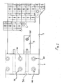
Fig. 1 is a side view of a magnet or magnetic yoke for a Magnetic Resonance Imaging apparatus according to this invention. -
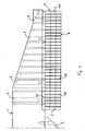
Fig. 2 is a plan view of a portion of a magnet or magnetic yoke for a Magnetic Resonance Imaging apparatus according to this invention. -
Fig. 3 is a side view of a detail of a magnet or magnetic yoke for a Magnetic Resonance Imaging apparatus according to this invention. -
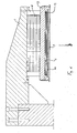
Fig. 4 is a plan view of a magnetic pole piece for a Magnetic Resonance Imaging apparatus according to this invention. -
Fig. 5 is a side view of a portion of a magnetic pole piece for a Magnetic Resonance Imaging apparatus according to this invention. -
Fig. 6 is a further side view of a magnetic pole piece for a Magnetic Resonance Imaging apparatus according to this invention. -
Figs. 7, 8 are plan views of two types of sheets for a magnetic pole piece for a Magnetic Resonance Imaging apparatus according to this invention. -
Fig. 9 is a plan view of a sheet pack for a magnetic pole piece for a Magnetic Resonance Imaging apparatus according to this invention. -
Fig. 10 is a plan view of a plate of a magnetic pole piece for a Magnetic Resonance Imaging apparatus according to this invention. -
Fig. 11 is a side view of a Magnetic Resonance Imaging apparatus according to this invention. -
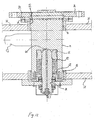
Fig. 12 is a side view of a construction detail of a Magnetic Resonance Imaging apparatus according to this invention. -
Fig. 13 is a rear view of a Magnetic Resonance Imaging apparatus according to this invention, with the two pole pieces on the same horizontal plane. -
Fig. 14 is a rear view of a Magnetic Resonance Imaging apparatus according to this invention, with the two pole pieces on the same vertical plane. -
Fig. 15 is a perspective view of a shaft for a Magnetic Resonance Imaging apparatus according to this invention. -
Fig. 16 is a perspective view of a pole piece for a Magnetic Resonance Imaging apparatus according to this invention, where the peripheral heating bands and the two flat D-shaped heaters are visible. - Particularly,
Fig. 1 shows a magnet for a Magnetic Resonance Imaging apparatus which has three open sides and delimits a patient receiving area. The magnet is composed of three yoke elements, i.e. two parallel magneticallypermeable yoke elements 1, 2 and atransverse yoke element 3 for connection of these twoparallel elements 1 and 2, whereby the magnet has a C shape. - In an apparatus with an overhangingly supported magnet, which essentially has a C- or laterally inverted U-shape, problems arise when the magnet is required to be rotated.
- In a Magnetic Resonance Imaging apparatus whose magnet keeps the same orientation relative to the gravitational field, the displacement of pole pieces is typically not a problem, as the forces acting in the pole piece support members are compensated for during fabrication.
- However, when a magnet rotation is required, e.g. for the examination of a body in certain positions or of certain body parts, problems often arise, as the magnet of the apparatus is essentially overhangingly supported by the support structure and is quite heavy. The rotation causes great bending stresses to act on the two arms of the C-shaped magnet, due to the heavy weights being involved. During and after the rotation of the magnet, a situation is generated in which the bending stress causes such deformations that the pole pieces of the magnet are substantially displaced relative to each other, whereby the homogeneity of the magnetic field is altered, and the quality of body images is affected.
- More generally, the pole piece support structure may be said to be mainly acted upon by two forces: the gravity force and the force of the magnetic field generated between the pole pieces.
- The force of the magnetic field between the pole pieces tends to bend the two arms of the C- or U- shape toward each other and is not affected by the spatial arrangement of the support structure, but remains essentially constant regardless of the spatial arrangement and the rotation of the apparatus.
- However, the gravitational force is directed downwards, as is known, and causes different stresses on the structure depending on the position of the support structure, i.e. generally the magnetic yoke. In fact, when the two arms of the C shape are one above the other, with vertically superimposed pole pieces, the force of the gravitational field acts in such a manner that the upper arm tends to bend downwards, whereas the lower arm tends to move toward the floor. In case of a 90° rotation, when the arms of the C shape are in side-by-side positions, gravity-induced stresses cause both arms to deform toward the floor in the same direction. All intermediate positions of the magnet, between the two above mentioned extreme conditions, cause a dramatic change of the stresses acting on the arms of the C-shape.
- These two forces, i.e. the force of the gravitational field and the force of the magnetic field sum up during normal operation and generate a variable stress depending on which position is taken by the magnet: if the arms of the C shape are one above the other, the force of the magnetic field tends to partly compensate for the gravity force, thereby reducing the stress on the lower arm of the C shape. After a 90° rotation, the force of the magnet field has no effect on the gravity force, as it acts perpendicular thereto, whereby two deformations along perpendicular planes are produced: the gravity force causes a downward deformation on the vertical plane, whereas the magnetic force acts on the horizontal plane, and draws the two arms of the C shape toward each other.
- For a magnet that is not intended to be rotated, a compensation for the above deformations may be attempted during design and fabrication, e.g. by a construction which preventively accounts for the expected magnet deformation, or by the well-known shimming mechanism, which corrects the magnetic-field and makes it uniform and parallel even in case of non homogeneous and parallel lines of flux, due to the gravitational force and the magnetic field force.
- Furthermore, for weight withstanding purposes, prior art overhangingly mounted apparatuses which are not designed for rotation are often loaded in a mechanical pre-stress condition, a bending stress essentially contrary to the stress that the apparatus is expected to receive in the assembled condition being induced by suitable design and assembly arrangements, to limit the deformation of the apparatus after installation.
- The arrangements used in prior art for non rotating magnets are not applicable to rotating magnets, as even the slightest rotation of a C-shaped magnet causes an overall change of the mechanical stress conditions, as mentioned above.
- Therefore, a prior art apparatus with a rotating C-shaped magnet often has the drawback of providing either a small imaging volume or a low image quality.
- As shown in
Fig. 1 , in bothparallel elements 1, 2, the end portion associated to thetransverse connection element 3 has a transverse wall for connecting the two parallel elements with thetransverse element 3, which has anend step 101, 102, for engagement of acorresponding end transverse element 3. - The
elements 1 and 2, which are perpendicular to and overhangingly supported by thetransverse element 3 are secured thereto by suitable fastener means 401, 402, which are oriented perpendicular to the longitudinal extension of thetransverse wall 3 and engage the twoparallel elements 1, 2 with thetransverse element 3 in the raised thickness of thisend step 101, 102. Referring now toFigs. 1 ,2 ,3 , further fastener means 503 are shown which are oriented parallel to the longitudinal extension of thetransverse wall 3, and engage the twoparallel elements 1, 2 with thetransverse element 3 at theend step 101, 102. - The fixation between the elements of the C-shaped structure of the magnetic yoke is further reinforced by
reinforcement member 5, which are positioned in the inwardly facing corners between theparallel elements 1, 2 and thetransverse element 3, and which are retained in position between theparallel elements 1, 2 and thetransverse element 3 by fastener means 105, 205. - Particularly, in the preferred embodiment of the Figures, the
reinforcement members 5 are each formed by a triangular member and may be provided in a variable number depending on the sturdiness required from the magnet. The weight and rigidity of the structure may be advantageously varied by providing a singletriangular member 5 extending essentially along the whole parallel element and transverse element coupling length, or one or more preferablytriangular reinforcement ribs - Particularly, in a preferred embodiment, two triangular reinforcement ribs are provided for each parallel element/transverse element pair, which is a good compromise between rigidity and lightness of the assembly.
- The fastener means are preferably provided in the form of screw fasteners, preferably having a head with a greater diameter than the cylindrical shank of the screw. Thus, the various parts of the magnet may be conveniently centered and assembled in the proper position.
- If the magnet, and therefore the pole pieces of a Magnetic Resonance Imaging apparatus are intended to be rotated, the pole pieces shall be constantly in a proper relative position, to form a highly homogeneous magnetic field and provide high quality images. For a rotating magnet, there is the risk that, as the direction of the gravity force on the magnetic yoke changes, due to the heavy weight of the latter and to the overhanging support of its parallel elements, small displacements may occur between the parallel elements and between the pole pieces, thereby causing unevenness and in homogeneity of the magnetic field.
- In all Magnetic Resonance Imaging apparatuses in which the magnet structure always has the same orientation with respect to gravity, any offset from the ideal position of the pole pieces, caused by gravity or by mutual magnetic attraction between the opposed pole pieces is accounted and compensated for during fabrication.
- However, a magnet according to the present invention assures that no or almost no relative displacement occurs between parallel elements, and between the pole pieces, whereby the magnetic field remains uniform and homogeneous even when the magnet is rotated, and assures that the image of the body under examination has a good quality.
- The magnet of this invention advantageously and essentially allows to avoid any relative displacement between the parts which compose the magnet so that, even upon rotation of the magnet, the magnetic field is essentially unaltered and optimal for a proper examination of the body in any position thereof, at least in the imaging volume. The structure is highly stable, and the deformation of the parts which compose the C-shaped magnet is insignificant.
- According to a further characteristic of this invention, as shown in
Figs. 11 and12 , the magnet is rotatably handled about an axis perpendicular to at least one axis of the cavity opening, particularly in the preferred arrangement of the figures the axis of rotation essentially passes through the center of the imaging volume of the apparatus, where imaging volume, as used herein, refers to the portion of the magnet-defined cavity in which the magnetic field has the best characteristics for imaging the body under examination. - In order that the magnet may be rotated about the preferred axis, it has a
coupling flange 30 in its transverse wall opposite the cavity, for coupling theshaft 31 to the transverse wall of the magnet, said transverse wall being rotatably mounted to asupport case 32 on rotatably and translatably supportingmeans 32, such as slide/rotary guides and/or roller bearings. - The
coupling flange 30 and thesupport case part 32 have mutually cooperating lock/release means for locking/releasing the rotation, which allow to change from a magnet rotation condition to a magnet stop condition. - The means for locking/releasing the magnet are provided in the form of two opposed and interconnected ring gears 36, 37, whereof one is integral with the
support case 32 and does not rotate, and the other is integral with theshaft 31 and rotates therewith. The ring gears are maintained in a stable mutual engagement condition by the force exerted by an elastic-member, and means are provided for moving the two ring gears to a disengagement condition against the action of theelastic member 39. - Particularly, according to a preferred embodiment, the elastic member is provided in the form of a Belleville spring, which ensures a highly strong attachment, adapted to maintain the two ring gears in a mutual engagement condition.
- The ring gears 36, 37 preferably have front teeth, which provide a more compact structure and a better and more accurate mesh between the teeth thereof.
- As shown in
Fig. 12 , the ring gear 36 associated to theshaft 31 is integral with thecoupling flange 30 and its teeth are directed opposite the magnet. - While the magnet is moving, its rotary motion is transmitted to the
shaft 31 by a shaft handling grip, which is formed by aradial lever 63 which is rotatably and/or translatably integral with the shaft; this lever is articulated to the rod of a hydraulic orpneumatic cylinder actuator 64, i.e. a linear actuator, which generates a rectilinear motion, to be turned into a rotary motion of the shaft by the action of the radial lever. - The
shaft 31 is preferably associated to thesupport case 32 by means of roller bearings, which are preferably placed at the ends of the shaft. - The linear actuator is itself connected by its lower portion to the case and, depending on the desired embodiment, may be stationary or translatable on a suitable guide with respect to it.
- In one embodiment, the
radial lever 63 is coupled with the rod of theactuator 64 by sliding means, which slide in the axial shaft translation direction, e.g. the lever has a perforated and thinned terminal, as shown inFig. 15 which is mounted on a bar that is held at its ends by aterminal fork 90 for connection with the rod. Thefork 90 has such a width that the bar held thereby is at least as long as or slightly longer than the translation stroke of the shaft. Therefore, a translational motion of the shaft and the associated radial lever does not involve an identical translational motion of the actuator, which stands still with respect to the case, as theradial lever 63 slides on the rod which is retained by thefork 90 of thelinear actuator 64. - In an alternative embodiment, the linear actuator has a slide guide, not shown, at its end associated to the support case, for allowing translational motion of the actuator, and the rod of the actuator has one degree of freedom, particularly of rotation, with respect to the radial lever. Hence, as the shaft is translated, it also drives into translation the linear actuator, which follows the shaft by translating on the slide guide that connects it to the support case.
- In a further alternative embodiment, the linear actuator is connected to the support case or to the radial lever with the interposition of a joint which allows it to tilt to accommodate the shaft translation. This is possible because such translational motion extends for so little, i.e. in a range of a few millimeters, that the substantial verticality of the linear actuator is not dramatically affected. As an alternative, the radial lever may be designed to have a joint which allows it to tilt relative to the shaft, to accommodate the translational motion of the shaft with respect to the actuator.
- As shown in
Figs 11 and12 , the ring gears 36, 37 and theBelleville spring 39 may be respectively displaced by hydraulic or pneumatic displacement means, and may be stressed thereby in the axial direction of theshaft 31. - Moreover, as shown in
Figs. 11 and12 , the end of theshaft 31 opposite the magnet is provided in the form of a hydraulic or pneumatic lock/release cylinder actuator , whose rod 50 projects out of the end of theshaft 31, and is mounted in such a manner as to be unable to rotate relative to theshaft 31 and is alternately subjected to the action of elastic means, such as theBelleville spring 39, which oppose the shaft translation toward disengagement of the ring gear teeth. The end of theshaft 31 opposite the magnet has a coaxial dead recess, which acts as a chamber 51 for a hydraulic or pneumatic lock/release cylinder actuator, and receives apiston 52 therein, which is mounted at the inner end of the rod 50, whereas the cylindrical recess is tightly closed by anend portion 54 at the head of the shaft, aspring 39 being provided between thepiston 52 and theend portion 54, whereas thepiston 52 tightly projects out of this end portion. - Therefore, when the magnet has to be rotated, the chamber of the lock/release actuator cylinder is, for instance, filled with oil whereby the Belleville spring is stressed in the compression direction by the hydraulic lock/release actuators. This causes the shaft to be translated relative to the support case, and particularly, in the embodiment of
Fig. 12 , the shaft moves toward the magnet, thereby bringing thering gear 37 integral with the magnet and with the shaft, to disengagement from the ring gear 36 integral with thesupport case 32. This releases the rotation of the magnet connected to the shaft, which is driven by the radial lever moved by the linear actuator. Once the rotation of the magnet is completed, the Belleville spring is released and brings the ring gears 36 and 37 into a mutual engagement position, thereby actually locking the rotation. - The relative position of the rotating shaft and the case may be controlled by sensors and/or photocells which ensure that shaft rotation only stops when the facing teeth of the ring gears 36 and 37 are in a proper mutually meshed position, so that meshing occurs with no shocks or undesired small rotations. As an alternative thereto or in combination therewith the magnet extreme positions may be also monitored, so that shaft rotation automatically stops when the shaft reaches either extreme position, i.e. when the magnet is in either C- or U-shaped position.
- This preferred arrangement provides a Magnetic Resonance Imaging apparatus which has a simple construction and is highly fail-safe, as the magnet may be only released when it is stressed by the lock/release piston which moves the two ring gears into disengagement and allows free rotation of the magnet. Hence, in case of a sudden failure of the apparatus or a sudden power failure, the action of the Belleville spring automatically moves the ring gears into a teeth mesh position, thereby causing the magnet to be immediately locked in position, and preventing it from uncontrollably and undesirably rotating.
- A further advantage as compared with prior art apparatuses is that any magnet lock/release and rotation action is performed by linear actuators, which have a simpler construction and ensure a higher reliability at lower costs as compared with normal prior art actuators.
- In another preferred embodiment, each pole piece as shown in
Figures 4 to 6 comprises at least onemagnetized layer 6, at least one magnetically permeable layer or plate 9, wherein the magnetically permeable plate 9 has a substantially circular shape and saidmagnetized layer 6 is formed by a plurality of adjacent and/or superimposedmagnetized blocks 106, which form a polygon essentially approximating the circular shape of the magnetically permeable plate 9. -
Fig. 4 showsfastener posts 7 for securing the pole piece 8 to the inner face of the correspondingparallel yoke element 1, 2, which are situated in the margin between the polygon and the circumference approximated by the polygon. The fastener posts 7 are placed in the recesses of the stepped peripheral edges formed by theblocks 106, which have a polygonal, particularly cubical shape or a rectangular section, and together form a polygonal layer with stepped peripheral edges. - The
posts 7 preferably have a tubular shape and are placed in centeringrecesses 206 for positioning theposts 7, wherein corresponding post ends may be introduced, the centeringrecesses 206 being complementary in size to the outside diameter of theposts 7 and/or to the outside diameter of the associated end of thepost 7, to allow proper insertion thereof, and to add rigidity to the assembly. The pole piece support structure also has similar centeringrecesses 501 on the surface facing toward the pole piece, for thefastener posts 7 of the pole piece. The fastener posts 7 have a tubular shape and contain a hole for the passage of an associated fastener means, such as a bolt and/or a screw. Furthermore thefastener posts 7 of the pole piece have a reduced or increased diameter at their free ends, corresponding to the diameter of the associated centeringrecesses 206 and/or to the corresponding diameter of the positioning recesses, to act as spacers with a predetermined stable size. The posts are pressed against the corresponding surfaces of the bottom sides of said recesses and actually remain compressed against them. - After a rotation that brings the pole pieces onto the same horizontal plane, the gravity force acts tangentially to the pole piece surface and causes a stress perpendicular to the stress obtained when the pole pieces are disposed on the same vertical plane. The posts that act as spacers and are connected by their end portions in the centering recesses prevent the pole pieces, and the components thereof, from moving relative to each other, as the gravity force changes.
- As shown in
Figs. 6 to 9 , a sheet pack 11 is provided in the pole piece, which is formed by at least onemetal sheet 13 with cuts thereon, which is positioned on the surface of the magnetically permeable plate 9 opposite the surface of the plate which is turned toward themagnetized layer 6 and is used to obtain a more homogeneous magnetic field. - A sheet pack 11 formed by multiple superimposed sheets is preferred. Particularly, as shown, the magnetically permeable plate 9 has a cup shape, having at least one, preferably two peripheral steps, which form a raised edge projecting out of the plate surface turned opposite the
magnetized layer 6, so that the sheet pack lies on the bottom 12 of the cup-shaped plate and under the known shimmingplate 70 which peripherally lies on the second step, hence at a distance from the bottom of the plate, equalling the thickness of the sheet pack 11. In a preferred embodiment, the pole piece has anelectromagnetic shield 13 which is placed in the end portion of the pole piece opposite the magnetized blocks, and over the shimming plate, so that the two electromagnetic shields of the two opposed, facing pole pieces are essentially turned toward the patient table 99. - As shown in
Figs. 7, 8, 9 , the sheet pack 11 has a plurality of cuts, the cuts of one sheet being located in different positions with respect to the cuts of the preceding or subsequent sheet in the sheet pack 11. This is achieved by providing that the cuts on each of the metal sheets are essentially non coincident betweenpair sheets 15 andodd sheets 16, with reference to the sheet positioning order in the sheet pack 11, and preferably the cuts are straight. This arrangement adds homogeneity to the magnetic field. - Moreover, in order to achieve a good image quality, the temperature of the magnetic pole pieces should be maintained constant, as any temperature change might cause an image quality drop.
- Furthermore, pole pieces are provided in which pole piece heating and temperature monitoring are optimized, whereby a preferred embodiment provides pole piece heater devices and pole piece temperature sensors; also, the pole piece may be adapted to receive the cables for the pole piece heater devices and temperature sensors. Suitable apertures are formed in the peripheral edges of the pole piece for the passage of the cables for the heaters and/or the temperature sensors, so that the pole piece is as compact as possible.
- As shown in
Fig. 10 , the apertures are twopassages 18, 19 formed on diametrically opposite locations of the plate 9 to prevent the passage of cables through the pole piece. - Particularly, electrical heaters are provided, which are in contact with said plate 9 and/or with the magnetized material and/or with the sheet pack 11, as shown in the figures.
- Furthermore, a particularly capillary and uniform heating arrangement may be provided by positioning at least some of these heaters within the
magnetized layer 6 and particularly between adjacentmagnetized blocks 106. - As shown in
Fig. 16 , the heaters may be placed on the externally accessible pole piece surface, which allows easier service and maintenance thereof. Particularly these heaters may beperipheral heaters 90, placed on the peripheral side surface of the edge of the pole piece and are not separate heaters but are provided continuously over the whole peripheral side surface of the pole piece, to form a peripheral heating edge. - Moreover, a more homogeneous heating arrangement may be obtained by providing flat heaters 91 over at least one face of the pole piece, these heaters preferably having the shape of a sector of a circle, more preferably a D shape, and being spaced over the face of the pole piece, to form an area therebetween which is not directly heated, as shown in
Fig. 16 . - In order that temperature detection and monitoring may be as accurate as possible, the temperature detecting and
monitoring sensors 97, as shown inFig. 16 , are positioned within the pole piece, and particularly temperature sensors may be provided level with the plate 9 and/or the magnetized material and/or the sheet pack 11. Furthermore, some of the temperature sensor means may be arranged to be positioned within themagnetized layer 6, preferably between adjacentmagnetized blocks 106. - Preferably, there may be two of these
temperature sensors 97, 97', placed inside the pole piece, particularly between the blocks and the sheet pack of the pole piece, in the area that is not directly heated by the two D-shaped heaters, as shown inFig. 16 . Therefore, temperature is sensed in an area that is not directly heated by heaters, whereby a more reliable detection is obtained, the temperature of the whole pole piece being more indicative than the temperature of a portion of it. - Also, the provision of two
sensors 97 advantageously avoids the need of dismantling and reassembling the pole piece and of subsequently recalibrating the shimming plate, in case of failure of one of the two pole pieces, because, with a very little starting cost, the apparatus may be arranged to continue operating with a single sensor. - Furthermore, the provision of two sensors allows temperature monitoring and detection in particularly difficult areas of the pole pieces, such as the areas of the magnetized blocks, with the highest accuracy, thereby assuring a good image quality.
-
Fig. 11 further shows the lateral slide guides 95 for the patient table 99 which, in a preferred embodiment, are provided in the form of a vertical support tab 94 which extends toward the pole piece from the sides of the patient table, said support shoulder or tab being associated to a guide and slide combination, which is preferably formed by a longitudinal slide having acylindrical head 93, cooperating with aconcave guide 92 which has a corresponding open profile. Thus the total height of the patient table 99 and the pole piece is considerably smaller than the heights of prior art patient tables and pole pieces, as guides are positioned sideways and the volume does not extend vertically. - The
longitudinal slide 93 is overhangingly supported toward the median area of the patient table surface and below said patient table surface by lower side tabs, branching off the two opposite longitudinal sides of the patient table. Theguide 92 is carried by the shoulder which is oriented parallel to the slide and/or to the side tabs of the patient table, and this guide is open on the side turned toward the inner face of the tabs which carry thelongitudinal slide 93. Aguide 92 and slide 93 combination is provided on each longitudinal side of the patient table. - The guide/slide combination may be advantageously provided in the form of a continuous guide which is coupled to a discontinuous slide or vice versa, to further and advantageously reduce the weight of the patient support device, which is intended to rotate with the magnet and therefore must have as light a weight as possible.
Claims (9)
- A Magnetic Resonance Imaging apparatus, comprising a magnet and at least a magnet support structure, the said magnet being capable of rotating relative to said support structure;
the said magnet comprising one or more permanent magnets or being provided in combination with means for generating the magnetic field which are resistive or superconducting, said magnet having at least one, preferably three open sides, and delimiting the patient receiving area, said magnet being composed of three yoke elements, i.e. two parallel magnetically permeable yoke elements (1, 2), and a transverse yoke element (3) for connection of said two parallel elements, said magnet thus having a C shape;
the said magnet having at least two pole pieces, are carried by the said parallel yoke elements on the sides facing each other and between which pole pieces a cavity is formed for containing at least one body under examination, which cavity is open on at least one side,
characterized in that
in both parallel elements (1, 2), the end portion associated to said transverse connection element (3) has a transverse wall for connecting the two parallel elements with the transverse element (3), wherein each of said parallel elements (1, 2) has an end step (101, 102), for engagement of a corresponding end (103, 203), of said transverse element (3). - A Magnetic Resonance Imaging apparatus as claimed in claim 1, characterized in that fastener means (401, 402) are provided which are oriented perpendicular to the longitudinal extension of said transverse wall (3), and which engage the two parallel elements (1, 2) with the transverse element (3) within the raised thickness of said end step (101, 102).
- A Magnetic Resonance Imaging apparatus as claimed in claim 1 or 2, characterized in that fastener means (503) are provided which are oriented parallel to the longitudinal extension of said transverse wall (3), and which engage the two parallel elements (1, 2) with said transverse element (3) at said end step (101, 102).
- A Magnetic Resonance Imaging apparatus as claimed in one or more of the preceding claims, characterized in that further reinforcement members are provided in the inwardly facing corners between said parallel elements (1, 2) and said transverse element (3), fastener means (105, 205) being provided between said reinforcement members and said parallel elements (1, 2) and/or said transverse element (3), for fastening and holding in position said reinforcement members.
- A Magnetic Resonance Imaging apparatus as claimed in one or more of the preceding claims, characterized in that said reinforcement members are formed by at least one single triangular member.
- A Magnetic Resonance Imaging apparatus as claimed in one or more of the preceding claims, characterized in that said triangular member is provided for each parallel element, and extends essentially along the whole parallel element and transverse element coupling length.
- A Magnetic Resonance Imaging apparatus as claimed in one or more of the preceding claims, characterized in that said reinforcement member is formed by one or more preferably triangular reinforcing ribs (5, 6).
- A Magnetic Resonance Imaging apparatus as claimed in one or more of the preceding claims, characterized in that two triangular reinforcing ribs are provided for each parallel element/transverse element pair.
- A Magnetic Resonance Imaging apparatus as claimed in one or more of the preceding claims, characterized in that said fastener means are provided in the form of screw fasteners.
Applications Claiming Priority (2)
| Application Number | Priority Date | Filing Date | Title |
|---|---|---|---|
| IT000016A ITSV20040016A1 (en) | 2004-04-13 | 2004-04-13 | NUCLEAR MAGNETIC RESONANCE MACHINE |
| EP05728188A EP1735630B1 (en) | 2004-04-13 | 2005-03-25 | Nuclear magnetic resonance apparatus |
Related Parent Applications (2)
| Application Number | Title | Priority Date | Filing Date |
|---|---|---|---|
| EP05728188A Division EP1735630B1 (en) | 2004-04-13 | 2005-03-25 | Nuclear magnetic resonance apparatus |
| EP05728188.3 Division | 2005-03-25 |
Publications (3)
| Publication Number | Publication Date |
|---|---|
| EP2113781A2 EP2113781A2 (en) | 2009-11-04 |
| EP2113781A3 EP2113781A3 (en) | 2009-11-25 |
| EP2113781B1 true EP2113781B1 (en) | 2011-02-16 |
Family
ID=34956265
Family Applications (2)
| Application Number | Title | Priority Date | Filing Date |
|---|---|---|---|
| EP05728188A Active EP1735630B1 (en) | 2004-04-13 | 2005-03-25 | Nuclear magnetic resonance apparatus |
| EP09167410A Active EP2113781B1 (en) | 2004-04-13 | 2005-03-25 | Nuclear magnetic resonance apparatus |
Family Applications Before (1)
| Application Number | Title | Priority Date | Filing Date |
|---|---|---|---|
| EP05728188A Active EP1735630B1 (en) | 2004-04-13 | 2005-03-25 | Nuclear magnetic resonance apparatus |
Country Status (7)
| Country | Link |
|---|---|
| US (1) | US7453264B2 (en) |
| EP (2) | EP1735630B1 (en) |
| AT (2) | ATE449970T1 (en) |
| DE (2) | DE602005026470D1 (en) |
| ES (2) | ES2337161T3 (en) |
| IT (1) | ITSV20040016A1 (en) |
| WO (1) | WO2005101047A1 (en) |
Families Citing this family (13)
| Publication number | Priority date | Publication date | Assignee | Title |
|---|---|---|---|---|
| ITSV20040020A1 (en) * | 2004-05-07 | 2004-08-07 | Esaote Spa | MAGNETIC STRUCTURE FOR MRI AND MRI MACHINES |
| US9448294B2 (en) | 2009-06-30 | 2016-09-20 | Aspect Imaging Ltd. | Cage in an MRD with a fastening/attenuating system |
| AU2010273298B2 (en) * | 2009-07-15 | 2014-10-23 | Viewray Technologies, Inc. | Method and apparatus for shielding a linear accelerator and a magnetic resonance imaging device from each other |
| IT1397713B1 (en) | 2010-01-22 | 2013-01-24 | Esaote Spa | MACHINE FOR NUCLEAR MAGNETIC RESONANCE WITH MEANS FOR THE CORRECTION OF THE HOMOGENITY OF THE MAGNETIC FIELD. |
| US11278461B2 (en) | 2010-07-07 | 2022-03-22 | Aspect Imaging Ltd. | Devices and methods for a neonate incubator, capsule and cart |
| US10076266B2 (en) | 2010-07-07 | 2018-09-18 | Aspect Imaging Ltd. | Devices and methods for a neonate incubator, capsule and cart |
| US9446263B2 (en) | 2013-03-15 | 2016-09-20 | Viewray Technologies, Inc. | Systems and methods for linear accelerator radiotherapy with magnetic resonance imaging |
| EP3423153B1 (en) | 2016-03-02 | 2021-05-19 | ViewRay Technologies, Inc. | Particle therapy with magnetic resonance imaging |
| US10224135B2 (en) | 2016-08-08 | 2019-03-05 | Aspect Imaging Ltd. | Device, system and method for obtaining a magnetic measurement with permanent magnets |
| US11287497B2 (en) | 2016-08-08 | 2022-03-29 | Aspect Imaging Ltd. | Device, system and method for obtaining a magnetic measurement with permanent magnets |
| US10847294B2 (en) | 2017-07-10 | 2020-11-24 | Aspect Imaging Ltd. | System for generating a magnetic field |
| CN116036499A (en) | 2017-12-06 | 2023-05-02 | 优瑞技术公司 | Optimization of multi-modality radiation therapy |
| CN114200366A (en) * | 2021-12-16 | 2022-03-18 | 武汉联影生命科学仪器有限公司 | Shimming device, magnetic field assembly, magnetic resonance imaging system and shimming method |
Family Cites Families (19)
| Publication number | Priority date | Publication date | Assignee | Title |
|---|---|---|---|---|
| JPH01242056A (en) * | 1988-03-24 | 1989-09-27 | Toshiba Corp | Magnetic resonance imaging apparatus |
| JPH0217038A (en) * | 1988-07-06 | 1990-01-22 | Toshiba Corp | Magnetic resonance imaging apparatus |
| US5207224A (en) * | 1988-12-09 | 1993-05-04 | Picker International, Ltd. | Magnetic resonance apparatus |
| US5252924A (en) * | 1991-11-18 | 1993-10-12 | Sumitomo Special Metals Co., Ltd. | Magnetic field generating apparatus for MRI |
| EP0479514B1 (en) | 1990-09-29 | 1998-07-01 | Sumitomo Special Metals Co., Ltd. | Magnetic field generating device used for MRI |
| US5153546A (en) * | 1991-06-03 | 1992-10-06 | General Electric Company | Open MRI magnet |
| US5343580A (en) * | 1991-12-04 | 1994-09-06 | Apogee Medical Products, Inc. | Indexing assembly for shoulder imaging |
| JP3367685B2 (en) * | 1992-05-20 | 2003-01-14 | 株式会社東芝 | Cable processing apparatus and magnetic resonance imaging apparatus having the same |
| US6023165A (en) * | 1992-09-28 | 2000-02-08 | Fonar Corporation | Nuclear magnetic resonance apparatus and methods of use and facilities for incorporating the same |
| JP2774777B2 (en) * | 1994-11-25 | 1998-07-09 | 株式会社日立メディコ | Magnetic resonance imaging device |
| GB2300712A (en) * | 1995-05-11 | 1996-11-13 | Elscint Ltd | Rotatable MRI magnet and patient support |
| JP3016545B2 (en) | 1995-06-12 | 2000-03-06 | 信越化学工業株式会社 | Permanent magnet magnetic circuit |
| DE69633683T2 (en) * | 1995-08-28 | 2006-03-09 | Shin-Etsu Chemical Co., Ltd. | Magnetic circuit arrangement with opposing permanent magnets |
| US6150818A (en) * | 1998-08-31 | 2000-11-21 | General Electric Company | Low eddy current and low hysteresis magnet pole faces in MR imaging |
| JP2000139874A (en) * | 1998-09-02 | 2000-05-23 | Sumitomo Special Metals Co Ltd | Magnetic field generator for mri |
| US7529575B2 (en) * | 1998-10-05 | 2009-05-05 | Esaote S.P.A. | Nuclear magnetic resonance imaging device |
| JP4617596B2 (en) * | 2001-04-24 | 2011-01-26 | 日立金属株式会社 | MRI magnetic field generator and MRI apparatus using the same |
| JP4214736B2 (en) * | 2002-08-08 | 2009-01-28 | 日立金属株式会社 | Magnetic field generator for MRI |
| US8064984B2 (en) * | 2003-03-18 | 2011-11-22 | Esaote S.P.A. | Magnetic resonance imaging apparatus |
-
2004
- 2004-04-13 IT IT000016A patent/ITSV20040016A1/en unknown
-
2005
- 2005-03-25 ES ES05728188T patent/ES2337161T3/en active Active
- 2005-03-25 WO PCT/EP2005/051399 patent/WO2005101047A1/en not_active Application Discontinuation
- 2005-03-25 AT AT05728188T patent/ATE449970T1/en not_active IP Right Cessation
- 2005-03-25 DE DE602005026470T patent/DE602005026470D1/en active Active
- 2005-03-25 EP EP05728188A patent/EP1735630B1/en active Active
- 2005-03-25 ES ES09167410T patent/ES2358311T3/en active Active
- 2005-03-25 AT AT09167410T patent/ATE498845T1/en not_active IP Right Cessation
- 2005-03-25 EP EP09167410A patent/EP2113781B1/en active Active
- 2005-03-25 US US11/578,343 patent/US7453264B2/en active Active
- 2005-03-25 DE DE602005017880T patent/DE602005017880D1/en active Active
Also Published As
| Publication number | Publication date |
|---|---|
| ATE498845T1 (en) | 2011-03-15 |
| US7453264B2 (en) | 2008-11-18 |
| EP1735630A1 (en) | 2006-12-27 |
| ES2337161T3 (en) | 2010-04-21 |
| US20070273378A1 (en) | 2007-11-29 |
| EP2113781A3 (en) | 2009-11-25 |
| DE602005017880D1 (en) | 2010-01-07 |
| EP2113781A2 (en) | 2009-11-04 |
| ES2358311T3 (en) | 2011-05-09 |
| DE602005026470D1 (en) | 2011-03-31 |
| EP1735630B1 (en) | 2009-11-25 |
| ATE449970T1 (en) | 2009-12-15 |
| WO2005101047A1 (en) | 2005-10-27 |
| ITSV20040016A1 (en) | 2004-07-13 |
Similar Documents
| Publication | Publication Date | Title |
|---|---|---|
| EP2113781B1 (en) | Nuclear magnetic resonance apparatus | |
| US8755863B2 (en) | Magnetic resonance imaging apparatus | |
| US9607745B2 (en) | Compact undulator system and methods | |
| EP1455196A2 (en) | Magnetic resonance imaging system | |
| CN109932374A (en) | A kind of device having the difunctional image checking of CT and DR | |
| EP0434247A2 (en) | Shield for a magnet | |
| US20140184225A1 (en) | Patient Tables and Magnetic Resonance Imaging Equipment | |
| JP2007053241A (en) | Superconducting magnet device | |
| US9562612B2 (en) | Pressure control valve assembly | |
| WO2006123273A2 (en) | A gantry mounted patient table and exchanger for medical imaging | |
| US5746093A (en) | Compensating device for compensation of a torque that depends on the angle of rotation, and medical stand with such a compensating device | |
| TWI757438B (en) | Antenna locator, system for measuring unwanted electromagnetic radiation, and method for measuring unwanted electromagnetic radiation | |
| JPH0579334B2 (en) | ||
| CN108364707B (en) | Ray collimator and ray radiation device | |
| CN217878720U (en) | Functional sofa impact testing device | |
| WO2006007876A1 (en) | A magnetic resonance apparatus | |
| CN111474473B (en) | Locked rotor test device for ultra-high-speed superconducting linear motor | |
| Temnykh et al. | Compact undulator for cornell high energy synchrotron source | |
| US6891112B2 (en) | Lift system for a platform, and weighing system equipped with the lift system | |
| CN110531290B (en) | Nuclear magnetic resonance apparatus | |
| CN210800625U (en) | Fixing support for optical instrument | |
| CN218032466U (en) | Displacement sensor with walking location structure | |
| CN220205279U (en) | Lifting structure and automobile calibration device | |
| CN218972254U (en) | Lifting assembly and lifting adjusting device | |
| CN214473886U (en) | Magnetic resonance apparatus and cryostat |
Legal Events
| Date | Code | Title | Description |
|---|---|---|---|
| PUAI | Public reference made under article 153(3) epc to a published international application that has entered the european phase |
Free format text: ORIGINAL CODE: 0009012 |
|
| PUAL | Search report despatched |
Free format text: ORIGINAL CODE: 0009013 |
|
| AC | Divisional application: reference to earlier application |
Ref document number: 1735630 Country of ref document: EP Kind code of ref document: P |
|
| AK | Designated contracting states |
Kind code of ref document: A2 Designated state(s): AT BE BG CH CY CZ DE DK EE ES FI FR GB GR HU IE IS IT LI LT LU MC NL PL PT RO SE SI SK TR |
|
| AK | Designated contracting states |
Kind code of ref document: A3 Designated state(s): AT BE BG CH CY CZ DE DK EE ES FI FR GB GR HU IE IS IT LI LT LU MC NL PL PT RO SE SI SK TR |
|
| 17P | Request for examination filed |
Effective date: 20100128 |
|
| 17Q | First examination report despatched |
Effective date: 20100310 |
|
| RTI1 | Title (correction) |
Free format text: NUCLEAR MAGNETIC RESONANCE APPARATUS |
|
| GRAP | Despatch of communication of intention to grant a patent |
Free format text: ORIGINAL CODE: EPIDOSNIGR1 |
|
| GRAS | Grant fee paid |
Free format text: ORIGINAL CODE: EPIDOSNIGR3 |
|
| GRAA | (expected) grant |
Free format text: ORIGINAL CODE: 0009210 |
|
| AC | Divisional application: reference to earlier application |
Ref document number: 1735630 Country of ref document: EP Kind code of ref document: P |
|
| AK | Designated contracting states |
Kind code of ref document: B1 Designated state(s): AT BE BG CH CY CZ DE DK EE ES FI FR GB GR HU IE IS IT LI LT LU MC NL PL PT RO SE SI SK TR |
|
| REG | Reference to a national code |
Ref country code: GB Ref legal event code: FG4D |
|
| REG | Reference to a national code |
Ref country code: CH Ref legal event code: EP |
|
| REG | Reference to a national code |
Ref country code: IE Ref legal event code: FG4D |
|
| REF | Corresponds to: |
Ref document number: 602005026470 Country of ref document: DE Date of ref document: 20110331 Kind code of ref document: P |
|
| REG | Reference to a national code |
Ref country code: DE Ref legal event code: R096 Ref document number: 602005026470 Country of ref document: DE Effective date: 20110331 |
|
| REG | Reference to a national code |
Ref country code: ES Ref legal event code: FG2A Ref document number: 2358311 Country of ref document: ES Kind code of ref document: T3 Effective date: 20110426 |
|
| REG | Reference to a national code |
Ref country code: NL Ref legal event code: VDEP Effective date: 20110216 |
|
| LTIE | Lt: invalidation of european patent or patent extension |
Effective date: 20110216 |
|
| PG25 | Lapsed in a contracting state [announced via postgrant information from national office to epo] |
Ref country code: PT Free format text: LAPSE BECAUSE OF FAILURE TO SUBMIT A TRANSLATION OF THE DESCRIPTION OR TO PAY THE FEE WITHIN THE PRESCRIBED TIME-LIMIT Effective date: 20110616 Ref country code: GR Free format text: LAPSE BECAUSE OF FAILURE TO SUBMIT A TRANSLATION OF THE DESCRIPTION OR TO PAY THE FEE WITHIN THE PRESCRIBED TIME-LIMIT Effective date: 20110517 Ref country code: SE Free format text: LAPSE BECAUSE OF FAILURE TO SUBMIT A TRANSLATION OF THE DESCRIPTION OR TO PAY THE FEE WITHIN THE PRESCRIBED TIME-LIMIT Effective date: 20110216 Ref country code: LT Free format text: LAPSE BECAUSE OF FAILURE TO SUBMIT A TRANSLATION OF THE DESCRIPTION OR TO PAY THE FEE WITHIN THE PRESCRIBED TIME-LIMIT Effective date: 20110216 |
|
| PG25 | Lapsed in a contracting state [announced via postgrant information from national office to epo] |
Ref country code: BG Free format text: LAPSE BECAUSE OF FAILURE TO SUBMIT A TRANSLATION OF THE DESCRIPTION OR TO PAY THE FEE WITHIN THE PRESCRIBED TIME-LIMIT Effective date: 20110516 Ref country code: CY Free format text: LAPSE BECAUSE OF FAILURE TO SUBMIT A TRANSLATION OF THE DESCRIPTION OR TO PAY THE FEE WITHIN THE PRESCRIBED TIME-LIMIT Effective date: 20110216 Ref country code: BE Free format text: LAPSE BECAUSE OF FAILURE TO SUBMIT A TRANSLATION OF THE DESCRIPTION OR TO PAY THE FEE WITHIN THE PRESCRIBED TIME-LIMIT Effective date: 20110216 Ref country code: AT Free format text: LAPSE BECAUSE OF FAILURE TO SUBMIT A TRANSLATION OF THE DESCRIPTION OR TO PAY THE FEE WITHIN THE PRESCRIBED TIME-LIMIT Effective date: 20110216 Ref country code: PL Free format text: LAPSE BECAUSE OF FAILURE TO SUBMIT A TRANSLATION OF THE DESCRIPTION OR TO PAY THE FEE WITHIN THE PRESCRIBED TIME-LIMIT Effective date: 20110216 Ref country code: FI Free format text: LAPSE BECAUSE OF FAILURE TO SUBMIT A TRANSLATION OF THE DESCRIPTION OR TO PAY THE FEE WITHIN THE PRESCRIBED TIME-LIMIT Effective date: 20110216 Ref country code: SI Free format text: LAPSE BECAUSE OF FAILURE TO SUBMIT A TRANSLATION OF THE DESCRIPTION OR TO PAY THE FEE WITHIN THE PRESCRIBED TIME-LIMIT Effective date: 20110216 Ref country code: NL Free format text: LAPSE BECAUSE OF FAILURE TO SUBMIT A TRANSLATION OF THE DESCRIPTION OR TO PAY THE FEE WITHIN THE PRESCRIBED TIME-LIMIT Effective date: 20110216 |
|
| PG25 | Lapsed in a contracting state [announced via postgrant information from national office to epo] |
Ref country code: MC Free format text: LAPSE BECAUSE OF NON-PAYMENT OF DUE FEES Effective date: 20110331 Ref country code: DK Free format text: LAPSE BECAUSE OF FAILURE TO SUBMIT A TRANSLATION OF THE DESCRIPTION OR TO PAY THE FEE WITHIN THE PRESCRIBED TIME-LIMIT Effective date: 20110216 Ref country code: EE Free format text: LAPSE BECAUSE OF FAILURE TO SUBMIT A TRANSLATION OF THE DESCRIPTION OR TO PAY THE FEE WITHIN THE PRESCRIBED TIME-LIMIT Effective date: 20110216 |
|
| REG | Reference to a national code |
Ref country code: CH Ref legal event code: PL |
|
| PG25 | Lapsed in a contracting state [announced via postgrant information from national office to epo] |
Ref country code: CZ Free format text: LAPSE BECAUSE OF FAILURE TO SUBMIT A TRANSLATION OF THE DESCRIPTION OR TO PAY THE FEE WITHIN THE PRESCRIBED TIME-LIMIT Effective date: 20110216 Ref country code: SK Free format text: LAPSE BECAUSE OF FAILURE TO SUBMIT A TRANSLATION OF THE DESCRIPTION OR TO PAY THE FEE WITHIN THE PRESCRIBED TIME-LIMIT Effective date: 20110216 Ref country code: RO Free format text: LAPSE BECAUSE OF FAILURE TO SUBMIT A TRANSLATION OF THE DESCRIPTION OR TO PAY THE FEE WITHIN THE PRESCRIBED TIME-LIMIT Effective date: 20110216 |
|
| PLBE | No opposition filed within time limit |
Free format text: ORIGINAL CODE: 0009261 |
|
| STAA | Information on the status of an ep patent application or granted ep patent |
Free format text: STATUS: NO OPPOSITION FILED WITHIN TIME LIMIT |
|
| REG | Reference to a national code |
Ref country code: IE Ref legal event code: MM4A |
|
| 26N | No opposition filed |
Effective date: 20111117 |
|
| PG25 | Lapsed in a contracting state [announced via postgrant information from national office to epo] |
Ref country code: LI Free format text: LAPSE BECAUSE OF NON-PAYMENT OF DUE FEES Effective date: 20110331 Ref country code: CH Free format text: LAPSE BECAUSE OF NON-PAYMENT OF DUE FEES Effective date: 20110331 Ref country code: IE Free format text: LAPSE BECAUSE OF NON-PAYMENT OF DUE FEES Effective date: 20110325 |
|
| REG | Reference to a national code |
Ref country code: DE Ref legal event code: R097 Ref document number: 602005026470 Country of ref document: DE Effective date: 20111117 |
|
| PGFP | Annual fee paid to national office [announced via postgrant information from national office to epo] |
Ref country code: GB Payment date: 20120305 Year of fee payment: 8 |
|
| PGFP | Annual fee paid to national office [announced via postgrant information from national office to epo] |
Ref country code: FR Payment date: 20120413 Year of fee payment: 8 |
|
| PGFP | Annual fee paid to national office [announced via postgrant information from national office to epo] |
Ref country code: ES Payment date: 20120329 Year of fee payment: 8 |
|
| PG25 | Lapsed in a contracting state [announced via postgrant information from national office to epo] |
Ref country code: LU Free format text: LAPSE BECAUSE OF NON-PAYMENT OF DUE FEES Effective date: 20110325 |
|
| PG25 | Lapsed in a contracting state [announced via postgrant information from national office to epo] |
Ref country code: IS Free format text: LAPSE BECAUSE OF FAILURE TO SUBMIT A TRANSLATION OF THE DESCRIPTION OR TO PAY THE FEE WITHIN THE PRESCRIBED TIME-LIMIT Effective date: 20110216 |
|
| PG25 | Lapsed in a contracting state [announced via postgrant information from national office to epo] |
Ref country code: TR Free format text: LAPSE BECAUSE OF FAILURE TO SUBMIT A TRANSLATION OF THE DESCRIPTION OR TO PAY THE FEE WITHIN THE PRESCRIBED TIME-LIMIT Effective date: 20110216 |
|
| PG25 | Lapsed in a contracting state [announced via postgrant information from national office to epo] |
Ref country code: HU Free format text: LAPSE BECAUSE OF FAILURE TO SUBMIT A TRANSLATION OF THE DESCRIPTION OR TO PAY THE FEE WITHIN THE PRESCRIBED TIME-LIMIT Effective date: 20110216 |
|
| GBPC | Gb: european patent ceased through non-payment of renewal fee |
Effective date: 20130325 |
|
| REG | Reference to a national code |
Ref country code: FR Ref legal event code: ST Effective date: 20131129 |
|
| PG25 | Lapsed in a contracting state [announced via postgrant information from national office to epo] |
Ref country code: FR Free format text: LAPSE BECAUSE OF NON-PAYMENT OF DUE FEES Effective date: 20130402 Ref country code: GB Free format text: LAPSE BECAUSE OF NON-PAYMENT OF DUE FEES Effective date: 20130325 |
|
| REG | Reference to a national code |
Ref country code: ES Ref legal event code: FD2A Effective date: 20140609 |
|
| PG25 | Lapsed in a contracting state [announced via postgrant information from national office to epo] |
Ref country code: ES Free format text: LAPSE BECAUSE OF NON-PAYMENT OF DUE FEES Effective date: 20130326 |
|
| PGFP | Annual fee paid to national office [announced via postgrant information from national office to epo] |
Ref country code: IT Payment date: 20230309 Year of fee payment: 19 Ref country code: DE Payment date: 20230314 Year of fee payment: 19 |
|
| P01 | Opt-out of the competence of the unified patent court (upc) registered |
Effective date: 20230426 |