EP2113745A2 - Bewegungsdämpfung in einer 3-D-Positionserfassungsvorrichtung - Google Patents
Bewegungsdämpfung in einer 3-D-Positionserfassungsvorrichtung Download PDFInfo
- Publication number
- EP2113745A2 EP2113745A2 EP09156865A EP09156865A EP2113745A2 EP 2113745 A2 EP2113745 A2 EP 2113745A2 EP 09156865 A EP09156865 A EP 09156865A EP 09156865 A EP09156865 A EP 09156865A EP 2113745 A2 EP2113745 A2 EP 2113745A2
- Authority
- EP
- European Patent Office
- Prior art keywords
- vector
- article
- orientation
- velocity
- time
- Prior art date
- Legal status (The legal status is an assumption and is not a legal conclusion. Google has not performed a legal analysis and makes no representation as to the accuracy of the status listed.)
- Withdrawn
Links
- 238000009499 grossing Methods 0.000 title description 3
- 239000013598 vector Substances 0.000 claims abstract description 74
- 238000000034 method Methods 0.000 claims abstract description 51
- 230000001133 acceleration Effects 0.000 claims abstract description 38
- 239000011159 matrix material Substances 0.000 claims abstract description 28
- 238000005259 measurement Methods 0.000 claims description 11
- 238000004364 calculation method Methods 0.000 claims description 9
- 238000004590 computer program Methods 0.000 claims description 4
- 229910014010 M2 x M3 Inorganic materials 0.000 claims description 3
- 238000012937 correction Methods 0.000 description 8
- 238000010586 diagram Methods 0.000 description 7
- 238000013213 extrapolation Methods 0.000 description 6
- 230000010354 integration Effects 0.000 description 2
- 230000003190 augmentative effect Effects 0.000 description 1
- 230000000694 effects Effects 0.000 description 1
- 238000000605 extraction Methods 0.000 description 1
- 239000000835 fiber Substances 0.000 description 1
- 230000001737 promoting effect Effects 0.000 description 1
- 238000011084 recovery Methods 0.000 description 1
- 230000001360 synchronised effect Effects 0.000 description 1
Images

Classifications
-
- G—PHYSICS
- G01—MEASURING; TESTING
- G01S—RADIO DIRECTION-FINDING; RADIO NAVIGATION; DETERMINING DISTANCE OR VELOCITY BY USE OF RADIO WAVES; LOCATING OR PRESENCE-DETECTING BY USE OF THE REFLECTION OR RERADIATION OF RADIO WAVES; ANALOGOUS ARRANGEMENTS USING OTHER WAVES
- G01S5/00—Position-fixing by co-ordinating two or more direction or position line determinations; Position-fixing by co-ordinating two or more distance determinations
- G01S5/18—Position-fixing by co-ordinating two or more direction or position line determinations; Position-fixing by co-ordinating two or more distance determinations using ultrasonic, sonic, or infrasonic waves
-
- G—PHYSICS
- G01—MEASURING; TESTING
- G01D—MEASURING NOT SPECIALLY ADAPTED FOR A SPECIFIC VARIABLE; ARRANGEMENTS FOR MEASURING TWO OR MORE VARIABLES NOT COVERED IN A SINGLE OTHER SUBCLASS; TARIFF METERING APPARATUS; MEASURING OR TESTING NOT OTHERWISE PROVIDED FOR
- G01D1/00—Measuring arrangements giving results other than momentary value of variable, of general application
-
- G—PHYSICS
- G01—MEASURING; TESTING
- G01S—RADIO DIRECTION-FINDING; RADIO NAVIGATION; DETERMINING DISTANCE OR VELOCITY BY USE OF RADIO WAVES; LOCATING OR PRESENCE-DETECTING BY USE OF THE REFLECTION OR RERADIATION OF RADIO WAVES; ANALOGOUS ARRANGEMENTS USING OTHER WAVES
- G01S15/00—Systems using the reflection or reradiation of acoustic waves, e.g. sonar systems
- G01S15/66—Sonar tracking systems
Definitions
- This invention relates to continuous positional and orientational tracking of an object in three dimensions, and optionally, the use of tracking data to control an onscreen pointer.
- either method may further comprise using ultrasonic readings to correct the velocity estimates and thereby estimated position, by modifying the historical velocity estimate when each new ultrasonic reading is received, to make the estimated position match the position given by the new ultrasonic measurement.
- a method of estimating position and orientation of an article comprising correcting orientation, and optionally velocity, by taking a plurality of readings from the output of three accelerometers mounted on the article, using three positions given by ultrasonic time-of-flight measurements, during transit between the first, second and third ultrasonic-derived positions, assuming that acceleration of the article between the first to the third said positions was substantially constant and verifying this against the plurality of accelerometer readings, calculating the acceleration vector at the second said position using the position and time information about the three known positions and comparing that calculated acceleration vector with one obtained from the accelerometers, and thereby re-calibrating the measurements taken from the accelerometers.
- the invention provides a computer program product carrying program steps which when executed on suitable hardware causes the hardware to carry out the steps of the any of the claimed methods and a method of controlling an on-screen pointer, comprising using the position and orientation information of the article derived using any preceding claim, and determining where a line through a predetermined one of the article's axes intersects a plane, which plane may be the plane of the screen.
- Position may be sensed using ultrasonic time-of-flight measurements between fixed and mobile components (such as a handheld games controller), with the readings supplemented by interim readings from accelerometers and gyroscopes.
- magnetometers may be used to provide an absolute directional reference based on the earth's magnetic field or an artificially generated field.
- the ultrasonic measurement may, for example, be as described in our co-pending WO-A-2007/003126 , the disclosure of which is incorporated herein by reference.
- the invention allows determination of complete real-time movement and orientation of a hand-held controller.
- the system is able to ascertain motion and orientation, provided by preferably 3 orthogonal accelerometers and preferably 3 orthogonal gyroscopes (and optionally magnetometers) respectively, to describe the motion, but with constant feedback/correction from every reliable ultrasonic position received.
- the subsequent motion is governed by the ultrasonic positions, with the inertial guidance of the accelerometers and gyroscopes filling in the motion for the microseconds in-between ultrasonic position readings.
- the small mismatches between the predicted position, the actual next ultrasonic position, and the extraction of the underlying motion from just ultrasonic readings, are used to calibrate the electronic components of the system, in an attempt to reduce errors to zero.
- this live-calibration substantially eliminates linear velocity drift from the accelerometers, and rotational drift from the gyroscopes enabling accurate knowledge of the controller's rotation and thus operation as a pointer.
- Such feedback also allows complete recovery from any initial conditions or an errored state.
- gyroscope and derivatives thereof, is used herein to refer to orientation detecting means having a similar function to a gyroscope or gyroscopic sensor. This term is used to include, but is in no means limited to, devices such as gyroscopes; fibre optic gyroscopes; laser gyroscopes; vibrating structure gyroscopes and magnetohydrodynamic sensors. The term is intended to encompass a single such detecting means or group thereof acting jointly or independently. This term is also used to refer to pairs accelerometers arranged to produce similar readings to those of gyroscopes, which may be through an electronic or software interface.
- a handheld controller or mobile component of the type described in WO-A-2007/003126 is augmented with sensors able to measure orientation and acceleration in three orthogonal axes such as three, preferably orthogonally mounted, gyroscopes and three, preferably orthogonally mounted, accelerometers.
- sensors able to measure orientation and acceleration in three orthogonal axes such as three, preferably orthogonally mounted, gyroscopes and three, preferably orthogonally mounted, accelerometers.
- These extra sensors can be polled more rapidly than the ultrasonic measurement system and by tracking relative movement of the controller, allow interpolation and extrapolation of the ultrasonic measurements of position and also allow orientation of the controller to be measured.
- the gyroscopes may be supplemented with magnetometers to further improve orientation sensing.
- the system seeks to calculate substantially continuous position and orientation of an object such as a handheld games controller or pointer, here referred to as "mobile component" from the following discrete information:
- the method is preferably able to recover from a complete absence of data, and return rapidly to the correct position and orientation.
- the method also allows any data that is assessed to be unreliable to be disregarded without undue error or instability.
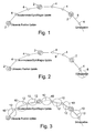
- Figure 1 shows the core problem. Relatively infrequent ultrasonic positional data points 2, are relatively reliable in terms of accuracy. More frequent updates 4 from the other hardware components (accelerometers, gyroscopes and optional magnetometers), which can contribute information to the controller's situation are also available. However, instead of simply knowing the object's position at the positions 2, the problem demands being able to calculate it at many intermediate points on the line 6 which interconnects the points 2 and 4.
- the position and orientation can be tracked, extrapolated beyond the last data input, enhanced when data is received and fed back with a number of corrections to counter drifting and error that is inherent in real hardware applications.
- the methods may be used separately, or preferably, in combination.
- This method allows the estimation of a continuous position (vector P ), and orientation (matrix O) of an article at time T, moveable from an initial situation at time T 0 , described by :
- This method is used to extrapolate the line 6 onwards from the last data input received from the controller. On the diagram, this extrapolation is marked by circle 8. This line represents an estimate of the trajectory of the mobile component which is being tracked.
- T Slice (T - T 0 )/N
- M MatrixCreate( T Slice * R 0 )
- O M 1 x M 2 x M 3 x ....(with N instances of M) .. x O 0
- P P 0 + V (T - T 0 )
- This method allows estimation of a continuous position (vector P ), velocity (vector V ) and orientation (matrix O) of an article at time T, which is between (and including) an initial time T 0 with its situation described by :
- this method is used to amend the preceding motion data when a new batch of accelerometer/gyroscope/magnetometer data comes in. This can be used retrospectively to correct the extrapolation derived in the method described above. Each of the parts of the line marked by circles 10 was established via this method; corrected from their previously extrapolated values which are indicated by broken lines 12.
- This method allows calculation of the situation at time T 1 , which can then be used as the initial conditions (at time T 0 ) for the first method above.
- T Slice (T - T 0 )/N
- R ⁇ Midslice R ⁇ Startslice + R ⁇ Half_inc
- R ⁇ Endslice R ⁇ Midslice + R ⁇ Half_inc
- a ⁇ Midslice A ⁇ Startslice + A ⁇ Half_inc
- a ⁇ Endslice A ⁇ Midslice + A ⁇ Half_inc
- F ⁇ Midslice F ⁇ Startslice + F ⁇ Half_inc
- F ⁇ Endslice F ⁇ Midslice + F ⁇ Midslice + F ⁇ Half_inc
- F True The direction of the true magnetic field F True is known, and we have a direction given by F Midslice that should match it, provided we transform F Midslice back into world space ( it's relative to the controller at present).
- a ⁇ W O midslice ⁇ A ⁇ Midslice ;
- This method uses ultrasonic readings to correct linear velocity estimates, and thus position.
- the dotted path 14 represents the path which was being tracked, complete with its interim corrections 4 from the more frequent accelerometer/gyroscope/magnetometer updates, and even an extrapolation up until the point of our most recent position.
- a new ultrasonic position (vector P) is received at time T.
- vector P the position of the object which are described above.
- This velocity increment propagates through the historical data to the present moment, yielding a current velocity that is increased by the increment and a new calculated P c that exactly matches P .
- This method corrects orientation, and optionally velocity, by taking a plurality of readings from the output of three accelerometers mounted at preferably at 90 degrees to each other and necessarily non-parallel to one another on the article, during transit between the three known positions, assuming that acceleration of the article between the first to the third known positions was substantially constant and verifying this against the plurality of accelerometer readings, calculating the acceleration vector at the second known position using the position and time information about the three known positions and comparing that calculated acceleration vector with the one obtained from the accelerometers (once rotated back into world space from the local space of the article).
- the orientation change to correct vector 18 to match vector 16 is calculated and applied to historical calculations from the time of the second ultrasonic reading 2'''. This reading is chosen because it can be confirmed via former and later ultrasonic readings, whether the assumption of constant accelerations holds true. Therefore the subsequent path of the tracked article can be recalculated with corrected accelerometer readings, from the time of T 2 to the present - see Figure 6 .
- P B P - P 2 Time change between P 1 and P 2
- T A T 2 - T 1 Time change between P and P 1
- T B T - T 1
- the methods typically will be implemented in software with connections to hardware accelerometers, gyroscopes, magnetometers, and ultrasonic transducers.
- the invention encompasses a computer program product, such as downloadable, software, firmware or a physical carrier such as a DVD carrying program steps which when executed on suitable hardware causes the hardware to carry out the steps of the claimed methods.
- the resulting measured motion of the mobile component will be subject to a degree of perturbation as a result of the level of noise and error present in the system.
- These perturbations may be smoothed by a variety of techniques. For example, values may be blended with a proportion of their previous value and a proportion of their new value, yielding a smoothness that takes into account past values whose significance diminishes over time.
- Such a smoothing method can be further refined by making those proportions themselves proportional to the difference between new and old values, thus large differences may force a faster or even instant adoption of the new value, whereas small differences allow a more gradual integration of new values, promoting smoothness. This achieves a system that is both smooth, and responsive to change.
- the user may ascertain where a line through one of the object's axes intersects an arbitrary fixed plane, in effect allowing the object to act as a pointing device.
Landscapes
- Engineering & Computer Science (AREA)
- Radar, Positioning & Navigation (AREA)
- Remote Sensing (AREA)
- Physics & Mathematics (AREA)
- General Physics & Mathematics (AREA)
- Computer Networks & Wireless Communication (AREA)
- Measurement Of Velocity Or Position Using Acoustic Or Ultrasonic Waves (AREA)
- Length Measuring Devices With Unspecified Measuring Means (AREA)
- Ultra Sonic Daignosis Equipment (AREA)
- Automation & Control Theory (AREA)
- Gyroscopes (AREA)
Applications Claiming Priority (2)
| Application Number | Priority Date | Filing Date | Title |
|---|---|---|---|
| GBGB0808081.4A GB0808081D0 (en) | 2008-05-02 | 2008-05-02 | Bridging ultrasonic position with accelerometer/gyroscope inertial guidance |
| GB0812533A GB2459718A (en) | 2008-05-02 | 2008-07-09 | Motion smoothing in 3D position sensing apparatus |
Publications (2)
| Publication Number | Publication Date |
|---|---|
| EP2113745A2 true EP2113745A2 (de) | 2009-11-04 |
| EP2113745A3 EP2113745A3 (de) | 2009-12-16 |
Family
ID=39537236
Family Applications (1)
| Application Number | Title | Priority Date | Filing Date |
|---|---|---|---|
| EP09156865A Withdrawn EP2113745A3 (de) | 2008-05-02 | 2009-03-31 | Bewegungsdämpfung in einer 3-D-Positionserfassungsvorrichtung |
Country Status (4)
| Country | Link |
|---|---|
| US (1) | US8868368B2 (de) |
| EP (1) | EP2113745A3 (de) |
| GB (2) | GB0808081D0 (de) |
| WO (1) | WO2009133338A2 (de) |
Families Citing this family (18)
| Publication number | Priority date | Publication date | Assignee | Title |
|---|---|---|---|---|
| US9590733B2 (en) | 2009-07-24 | 2017-03-07 | Corning Optical Communications LLC | Location tracking using fiber optic array cables and related systems and methods |
| AU2011232897B2 (en) | 2010-03-31 | 2015-11-05 | Corning Optical Communications LLC | Localization services in optical fiber-based distributed communications components and systems, and related methods |
| US8570914B2 (en) | 2010-08-09 | 2013-10-29 | Corning Cable Systems Llc | Apparatuses, systems, and methods for determining location of a mobile device(s) in a distributed antenna system(s) |
| CN102052921B (zh) * | 2010-11-19 | 2012-08-22 | 哈尔滨工程大学 | 一种单轴旋转捷联惯导系统初始航向的确定方法 |
| JP5459678B2 (ja) * | 2011-02-17 | 2014-04-02 | 株式会社東芝 | 移動体画像追尾装置 |
| US9279680B2 (en) * | 2012-03-15 | 2016-03-08 | Blackberry Limited | Methods and devices for determining orientation |
| US9781553B2 (en) | 2012-04-24 | 2017-10-03 | Corning Optical Communications LLC | Location based services in a distributed communication system, and related components and methods |
| US10215587B2 (en) | 2012-05-18 | 2019-02-26 | Trx Systems, Inc. | Method for step detection and gait direction estimation |
| WO2013181247A1 (en) | 2012-05-29 | 2013-12-05 | Corning Cable Systems Llc | Ultrasound-based localization of client devices with inertial navigation supplement in distributed communication systems and related devices and methods |
| WO2013188597A2 (en) | 2012-06-12 | 2013-12-19 | Amrit Bandyopadhyay | Irregular feature mapping |
| US9158864B2 (en) | 2012-12-21 | 2015-10-13 | Corning Optical Communications Wireless Ltd | Systems, methods, and devices for documenting a location of installed equipment |
| WO2014176033A1 (en) * | 2013-04-25 | 2014-10-30 | Corning Optical Communications LLC | Ultrasound-based location determination and inertial navigation with accuracy improvement in determining client device location |
| US10172443B2 (en) * | 2013-08-11 | 2019-01-08 | Yong-Jing Wang | Oral care tools and systems |
| US10726738B1 (en) * | 2013-08-22 | 2020-07-28 | Moov Inc. | Automated fitness coaching based on motion data |
| US9648580B1 (en) | 2016-03-23 | 2017-05-09 | Corning Optical Communications Wireless Ltd | Identifying remote units in a wireless distribution system (WDS) based on assigned unique temporal delay patterns |
| CN108733211B (zh) | 2017-04-21 | 2020-05-22 | 宏达国际电子股份有限公司 | 追踪系统、其操作方法、控制器、及电脑可读取记录媒体 |
| EP3540463B1 (de) * | 2018-03-09 | 2022-06-01 | Tata Consultancy Services Limited | Radar- und ultraschallsensorbasierte echtzeitverfolgung eines sich bewegenden objekts |
| CN110108902B (zh) * | 2019-05-23 | 2021-02-02 | 电子科技大学 | 用于三维非正交超声波阵列测风装置的测量误差校正方法 |
Citations (1)
| Publication number | Priority date | Publication date | Assignee | Title |
|---|---|---|---|---|
| WO2007003126A1 (fr) | 2005-07-02 | 2007-01-11 | Huawei Technologies Co., Ltd. | Procede pour transmettre des donnees courtes pendant un appel de groupe dans un systeme de communication sans fil |
Family Cites Families (21)
| Publication number | Priority date | Publication date | Assignee | Title |
|---|---|---|---|---|
| US3301508A (en) * | 1961-06-07 | 1967-01-31 | United Aircraft Corp | Guidance system with stellar correction |
| JPH07104145B2 (ja) * | 1989-10-11 | 1995-11-13 | 株式会社ミツトヨ | 位置検出装置の出力タイミング補間方法 |
| US5229551A (en) * | 1991-11-04 | 1993-07-20 | Summagraphics Corporation | Hysteresis compensation for a digitizer tablet |
| IL122578A (en) * | 1997-12-12 | 2000-08-13 | Super Dimension Ltd | Wireless six-degree-of-freedom locator |
| US6176837B1 (en) * | 1998-04-17 | 2001-01-23 | Massachusetts Institute Of Technology | Motion tracking system |
| JP2000078614A (ja) * | 1998-09-02 | 2000-03-14 | Sony Corp | 画像記録装置 |
| US6516213B1 (en) * | 1999-09-03 | 2003-02-04 | Robin Medical, Inc. | Method and apparatus to estimate location and orientation of objects during magnetic resonance imaging |
| US6823602B2 (en) * | 2001-02-23 | 2004-11-30 | University Technologies International Inc. | Continuous measurement-while-drilling surveying |
| AU2003261318A1 (en) * | 2002-08-01 | 2004-02-23 | The Charles Stark Draper Laboratory, Inc. | Borehole navigation system |
| WO2004056425A2 (en) * | 2002-12-19 | 2004-07-08 | Fortescue Corporation | Method and apparatus for determining orientation and position of a moveable object |
| US7028546B2 (en) * | 2003-10-21 | 2006-04-18 | Instrumented Sensor Technology, Inc. | Data recorder |
| JP5053078B2 (ja) * | 2004-04-30 | 2012-10-17 | ヒルクレスト・ラボラトリーズ・インコーポレイテッド | ハンドヘルドポインティングデバイス及びその作動方法 |
| IL165314A (en) * | 2004-11-21 | 2009-08-03 | Elbit Ltd | Electromagnetic tracker |
| JP4426432B2 (ja) * | 2004-12-17 | 2010-03-03 | 本田技研工業株式会社 | 脚体運動補助装具の補助モーメント制御方法 |
| CA2605177C (en) * | 2005-04-19 | 2011-06-21 | Jaymart Sensors, Llc | Miniaturized inertial measurement unit and associated methods |
| JP2007041733A (ja) * | 2005-08-01 | 2007-02-15 | Toyota Motor Corp | 運動体の姿勢角検出装置 |
| US20070113652A1 (en) * | 2005-10-07 | 2007-05-24 | Renken Wayne G | Wireless Position Sensing Wafer |
| KR101185144B1 (ko) * | 2006-01-24 | 2012-09-24 | 삼성전자주식회사 | 제스쳐의 2차원 궤적을 추정하는 방법 및 장치 |
| KR100711261B1 (ko) * | 2006-06-21 | 2007-04-25 | (주)마이크로인피니티 | 입력 장치의 공간 인식 방법 및 그 장치 |
| US7826999B1 (en) * | 2007-08-20 | 2010-11-02 | Pni Corporation | Magnetic tilt compensated heading compass with adaptive zoffset |
| KR101472842B1 (ko) * | 2007-09-11 | 2014-12-16 | 삼성전자 주식회사 | 움직임을 인식하는 장치 및 방법 |
-
2008
- 2008-05-02 GB GBGB0808081.4A patent/GB0808081D0/en not_active Ceased
- 2008-07-09 GB GB0812533A patent/GB2459718A/en not_active Withdrawn
-
2009
- 2009-03-31 EP EP09156865A patent/EP2113745A3/de not_active Withdrawn
- 2009-04-02 WO PCT/GB2009/000873 patent/WO2009133338A2/en active Application Filing
-
2010
- 2010-09-13 US US12/881,093 patent/US8868368B2/en not_active Expired - Fee Related
Patent Citations (1)
| Publication number | Priority date | Publication date | Assignee | Title |
|---|---|---|---|---|
| WO2007003126A1 (fr) | 2005-07-02 | 2007-01-11 | Huawei Technologies Co., Ltd. | Procede pour transmettre des donnees courtes pendant un appel de groupe dans un systeme de communication sans fil |
Also Published As
| Publication number | Publication date |
|---|---|
| GB2459718A (en) | 2009-11-04 |
| WO2009133338A2 (en) | 2009-11-05 |
| GB0812533D0 (en) | 2008-08-13 |
| GB0808081D0 (en) | 2008-06-11 |
| US20110071785A1 (en) | 2011-03-24 |
| US8868368B2 (en) | 2014-10-21 |
| WO2009133338A3 (en) | 2010-12-02 |
| EP2113745A3 (de) | 2009-12-16 |
Similar Documents
| Publication | Publication Date | Title |
|---|---|---|
| US8868368B2 (en) | Motion smoothing in 3-D position sensing apparatus | |
| US10323501B2 (en) | Method and apparatus for generating weighted average survey | |
| JP6094026B2 (ja) | 姿勢判定方法、位置算出方法及び姿勢判定装置 | |
| US6409687B1 (en) | Motion tracking system | |
| JP4199553B2 (ja) | ハイブリッド航法装置 | |
| EP2583059B1 (de) | Verbesserter kompass | |
| EP2901104B1 (de) | Verbessertes trägheitsnavigationssystem und -verfahren | |
| EP1983304B1 (de) | Kursstabilisierung für unterstützte Trägheitsnavigationssysteme | |
| EP3645836A1 (de) | System und verfahren zur erzeugung einer ausgabe einer bohrlochträgheitsmesseinheit | |
| US6381858B1 (en) | Method for calculating gyroscopic wellbore surveys including correction for unexpected instrument movement | |
| CN107747953A (zh) | 一种多敏感器数据与轨道信息时间同步方法 | |
| JPH0328714A (ja) | 走査型センサ用測定および制御システム | |
| JP4729197B2 (ja) | 物体の姿勢検出装置および整数バイアス再決定方法 | |
| EP2930467A1 (de) | System und Verfahren zur Messung der Neigung einer beweglichen Plattform mit Bezug auf die Schwerkraft | |
| EP3123209B1 (de) | Absolutvektor-gravimeter und verfahren zur messung eines absoluten schwerkraftvektors | |
| US6588117B1 (en) | Apparatus with gyroscopes and accelerometers for determining the attitudes of an aerodyne | |
| JP6383907B2 (ja) | 車輌位置計測装置及び方法 | |
| RU2539131C1 (ru) | Бесплатформенная интегрированная навигационная система средней точности для мобильного наземного объекта | |
| JP4343581B2 (ja) | 移動体の姿勢検出装置 | |
| JP2015004593A (ja) | ナビゲーション装置 | |
| KR101140379B1 (ko) | 리 대수 및 칼만 필터를 이용한 자세 추정 방법 및 장치 | |
| RU2754396C1 (ru) | Адаптивный способ коррекции углов ориентации БИНС | |
| WO2024185856A1 (ja) | 角速度センサの補正方法、角速度センサの補正プログラム、および、角速度センサシステム | |
| JP2016109609A (ja) | 姿勢推定装置及び姿勢推定装置の制御プログラム | |
| Ailneni et al. | Characterization of MEMS based inertial measurement unit |
Legal Events
| Date | Code | Title | Description |
|---|---|---|---|
| PUAI | Public reference made under article 153(3) epc to a published international application that has entered the european phase |
Free format text: ORIGINAL CODE: 0009012 |
|
| AK | Designated contracting states |
Kind code of ref document: A2 Designated state(s): AT BE BG CH CY CZ DE DK EE ES FI FR GB GR HR HU IE IS IT LI LT LU LV MC MK MT NL NO PL PT RO SE SI SK TR |
|
| AX | Request for extension of the european patent |
Extension state: AL BA RS |
|
| PUAL | Search report despatched |
Free format text: ORIGINAL CODE: 0009013 |
|
| AK | Designated contracting states |
Kind code of ref document: A3 Designated state(s): AT BE BG CH CY CZ DE DK EE ES FI FR GB GR HR HU IE IS IT LI LT LU LV MC MK MT NL NO PL PT RO SE SI SK TR |
|
| AX | Request for extension of the european patent |
Extension state: AL BA RS |
|
| AKY | No designation fees paid | ||
| REG | Reference to a national code |
Ref country code: DE Ref legal event code: 8566 |
|
| STAA | Information on the status of an ep patent application or granted ep patent |
Free format text: STATUS: THE APPLICATION IS DEEMED TO BE WITHDRAWN |
|
| 18D | Application deemed to be withdrawn |
Effective date: 20100617 |