EP2113724A1 - Air conditioner - Google Patents
Air conditioner Download PDFInfo
- Publication number
- EP2113724A1 EP2113724A1 EP08711641A EP08711641A EP2113724A1 EP 2113724 A1 EP2113724 A1 EP 2113724A1 EP 08711641 A EP08711641 A EP 08711641A EP 08711641 A EP08711641 A EP 08711641A EP 2113724 A1 EP2113724 A1 EP 2113724A1
- Authority
- EP
- European Patent Office
- Prior art keywords
- air conditioner
- fan
- engine driven
- heat pump
- top board
- Prior art date
- Legal status (The legal status is an assumption and is not a legal conclusion. Google has not performed a legal analysis and makes no representation as to the accuracy of the status listed.)
- Withdrawn
Links
- 238000010276 construction Methods 0.000 claims abstract description 18
- 230000003014 reinforcing effect Effects 0.000 claims abstract description 13
- 229920005989 resin Polymers 0.000 claims abstract description 10
- 239000011347 resin Substances 0.000 claims abstract description 10
- 239000012779 reinforcing material Substances 0.000 claims abstract description 7
- 238000009423 ventilation Methods 0.000 claims description 7
- 239000005022 packaging material Substances 0.000 abstract description 7
- 238000000465 moulding Methods 0.000 abstract description 4
- 230000002093 peripheral effect Effects 0.000 abstract description 3
- 239000003570 air Substances 0.000 description 39
- 239000012080 ambient air Substances 0.000 description 6
- 239000000463 material Substances 0.000 description 4
- 238000004806 packaging method and process Methods 0.000 description 3
- PPBRXRYQALVLMV-UHFFFAOYSA-N Styrene Chemical compound C=CC1=CC=CC=C1 PPBRXRYQALVLMV-UHFFFAOYSA-N 0.000 description 2
- 239000002184 metal Substances 0.000 description 2
- 230000001681 protective effect Effects 0.000 description 2
- 239000003507 refrigerant Substances 0.000 description 2
- 239000007787 solid Substances 0.000 description 2
- 238000011144 upstream manufacturing Methods 0.000 description 2
- 230000003247 decreasing effect Effects 0.000 description 1
- 238000005516 engineering process Methods 0.000 description 1
- 239000003822 epoxy resin Substances 0.000 description 1
- 239000006260 foam Substances 0.000 description 1
- 238000001746 injection moulding Methods 0.000 description 1
- 238000004519 manufacturing process Methods 0.000 description 1
- 238000000034 method Methods 0.000 description 1
- 229920000647 polyepoxide Polymers 0.000 description 1
- 229920006327 polystyrene foam Polymers 0.000 description 1
- 229910001220 stainless steel Inorganic materials 0.000 description 1
- 239000010935 stainless steel Substances 0.000 description 1
- 229920003002 synthetic resin Polymers 0.000 description 1
- 239000000057 synthetic resin Substances 0.000 description 1
Images


Classifications
-
- F—MECHANICAL ENGINEERING; LIGHTING; HEATING; WEAPONS; BLASTING
- F24—HEATING; RANGES; VENTILATING
- F24F—AIR-CONDITIONING; AIR-HUMIDIFICATION; VENTILATION; USE OF AIR CURRENTS FOR SCREENING
- F24F5/00—Air-conditioning systems or apparatus not covered by F24F1/00 or F24F3/00, e.g. using solar heat or combined with household units such as an oven or water heater
-
- F—MECHANICAL ENGINEERING; LIGHTING; HEATING; WEAPONS; BLASTING
- F24—HEATING; RANGES; VENTILATING
- F24F—AIR-CONDITIONING; AIR-HUMIDIFICATION; VENTILATION; USE OF AIR CURRENTS FOR SCREENING
- F24F1/00—Room units for air-conditioning, e.g. separate or self-contained units or units receiving primary air from a central station
- F24F1/06—Separate outdoor units, e.g. outdoor unit to be linked to a separate room comprising a compressor and a heat exchanger
- F24F1/38—Fan details of outdoor units, e.g. bell-mouth shaped inlets or fan mountings
-
- F—MECHANICAL ENGINEERING; LIGHTING; HEATING; WEAPONS; BLASTING
- F04—POSITIVE - DISPLACEMENT MACHINES FOR LIQUIDS; PUMPS FOR LIQUIDS OR ELASTIC FLUIDS
- F04D—NON-POSITIVE-DISPLACEMENT PUMPS
- F04D29/00—Details, component parts, or accessories
- F04D29/40—Casings; Connections of working fluid
- F04D29/52—Casings; Connections of working fluid for axial pumps
- F04D29/54—Fluid-guiding means, e.g. diffusers
-
- F—MECHANICAL ENGINEERING; LIGHTING; HEATING; WEAPONS; BLASTING
- F24—HEATING; RANGES; VENTILATING
- F24F—AIR-CONDITIONING; AIR-HUMIDIFICATION; VENTILATION; USE OF AIR CURRENTS FOR SCREENING
- F24F2221/00—Details or features not otherwise provided for
- F24F2221/12—Details or features not otherwise provided for transportable
Definitions
- the present invention relates to a structural technology of an air conditioner having a top-blown ventilation construction.
- a fan shroud formed around a fan in an air conditioner.
- the fan shroud is a guide formed so as to introduce a blown air to one direction.
- a top-blown air conditioner that inhales an ambient air from the side thereof so as to blast it out toward a top board thereof.
- a fan shroud which an opening end of an air outlet of the top board is formed so as to be projected upward, i.e., outside of the air conditioner.
- JP 1998-89726 there is well known a fan shroud, which an opening edge of an air outlet of the top board is formed so as to be projected inside of the air conditioner.
- the air conditioner When the air conditioner is transported by a truck during the shipment from a factory or during the delivery to a customer, it is slung into a truck box using a belt or the like, so as to prevent it from being dropped and fell down. In this case, the air conditioner is slung and tightly fixed into the truck box, so as to prevent a collapse of cargo.
- the air conditioner which the fan shroud thereof is formed so as to be projected outside of the air conditioner, is provided at the upper portion thereof with particular packaging materials made from lumber or the like and having a concave shape corresponding to a convex portion by the fan shroud, so that the top board and the fan shroud thereof is not damaged due to the load by the sling.
- the air conditioner is slung so as not to cover the fan shroud and transported.
- the air conditioner at which the fan shroud disclosed in JP 1998-89726 is formed so as to be projected inside of the air conditioner, i.e., rectangular solid air conditioner having a flat upper portion it is transported using the packaging materials such as styrene foam as protective materials, so as to protect the edge, i.e., the periphery of the fan shroud from the load due to the sling.
- the packaging materials such as styrene foam as protective materials
- an air conditioner of the present invention which is an air conditioner having a top blown ventilating construction
- fan shrouds are provided so that they are projected from a top board of the air conditioner therein and wherein the top board is provided across the longitudinal direction of the periphery thereof with a reinforcing material.
- the air conditioner can be approximately constructed as an rectangular solid, and it is provided at belt supporting portions that support belts or the like used for fixing during the packaging therein with belt supporting pads as a reinforcing material, so that packaging materials are unnecessary during the delivery of the air conditioner.
- Belt supporting pads are provided as the reinforcing material, across the whole length in a longitudinal direction of the periphery of the top board, i.e., across the whole length in a width direction of the air conditioner, and the fan shrouds are incorporated into the air conditioner, so that belt supporting portions during the packaging can be freely selected.
- the height of the outdoor heat exchanger can be increased by the portions at which the fan shrouds are projected outside of the air conditioner, whereby heat exchange capacity of the air conditioner can be increased, in comparison to the conventional air conditioner having the same height as the air conditioner of the present invention.
- the fan shrouds are made from resin, and it is wound around an opening portion therein with a reinforcing board. Due to the above construction, as the fan shrouds are made from resin, mass production can be efficiently performed. As the fan shrouds are made from resin, rigidity of the fan shrouds is decreased, but deformation due to lack of the rigidity can be minimized, by reinforcing the periphery of the fan shrouds using a reinforcing board. Accordingly, the clearance between the fan and the fan shroud can be minimized, so that air volume efficiency can be improved.
- the engine driven heat pump 1 is comprised of two device chambers vertically separated.
- the upper device chamber is a heat exchange chamber 10, and the lower one is an equipment chamber 20.
- the heat exchange chamber 10 is a device chamber having a construction capable of ventilating an ambient air for exchanging heats in outdoor heat exchangers 11, 11, the upper surface of which is covered with a top board 15.
- the heat exchange chamber 10 is provided with the outdoor heat exchangers 11, 11, a radiator (not shown), fans 12, 12 and fan electric motors 13, 13 or the like.
- the outdoor heat exchangers 11, 11 are arranged at two places of the front and back surfaces of the heat exchange chamber 10.
- the fans 12, 12 are disposed at the upper portion of the heat exchange chamber 10, and are driven by the fan electric motors 13, 13 arranged near them.
- the fan electric motors 13, 13 are provided with central axes of the fans 12, 12, and arranged inside of the heat exchange chamber 10 in the present embodiment.
- the ambient air which is inhaled from the front and back surfaces of the heat exchange chamber 10 by driving the fans 12, 12, passes through the outdoor heat exchangers 11, 11 so as to exchange heats.
- the ambient air is vented so as to blast out to the top surface side of the engine driven heat pump 1 (to the side of the top board 15). Due to the ventilation construction, the heat exchange is performed in the radiator (not shown) as well.
- the ventilation construction by which the ambient air inhaled through the outdoor heat exchangers 11, 11 by driving the fans 12, 12 is blasted out to the side of the top board 15 arranged at the top surface side of the engine driven heat pump 1, is a construction referred to as so-called “top blown ventilation construction", which is heavily used in large size air conditioners.
- the equipment chamber 20 is an approximately hermetically sealed device chamber that communicates with the outside only through a ventilating opening (not shown), an engine intake pipe (not shown) and an engine exhaust pipe (not shown).
- the equipment chamber 20 is constructed so that the periphery of the side surface thereof is covered with an outer plate 25.
- the equipment chamber 20 is arranged therein with major equipments of the engine driven heat pump 1 such as engine system equipments, refrigerant circuit equipments and an electric panel box (all of them are not shown).
- An engine 22 and associated compartments or the like are arranged as the engine system equipment.
- the engine driven heat pump 1 as one example of the air conditioner according to the present invention are provided therein with the heat exchange chamber 10 and the device chamber 20, and includes the top blown ventilating construction that blasts out the ambient air inhaled in the heat exchange chamber 10 upward.
- a fan shroud 30 as one example of the fan shroud according to the present invention will be described in detail, with reference to Fig. 2 .
- Fig. 2 to explain clearly, each one of one or more (two in the present embodiment) fans 12, 12 and fan electric motors 13, 13 as well as the fan shrouds 30, 30 provided corresponding to them or the like is illustrated.
- the outer plate 25, the fan electric motor mounting member, aftermentioned belt supporting pad 40 or the like are omitted.
- the fan shroud 30 is an approximately cylindrical ventilating guide disposed around the fan 12, so as to introduce the ventilation by the fan 12 to one direction.
- the ventilation in the heat exchange chamber 10 of the present embodiment is constructed so that it passes from the side of the fan electric motor 13 through the inside of the fan shroud 30 to the outside of the engine driven heat pump 1, by driving the fan 12 (see Fig. 2 ).
- the fan shroud 30 of the present embodiment is provided so as to project from the inner surface (the lower surface) of the top board 15 into the engine driven heat pump 1 (more strictly, into the heat exchange chamber 10).
- the fan shroud 30 of the present embodiment is formed by an integral moulding (for example, an injection moulding or the like) using resin having sufficient thermal resistance such as epoxy resin, synthetic resin, together with the top board 15.
- a reinforcing board 31 is wound around the outer peripheral edge an opening portion, at the inner end portion of the engine driven heat pump 1 (at the upstream side of the ventilating construction).
- the reinforcing board 31 is one embodiment of a reinforcing board according to the present invention, and is made from a metal having high rigidity.
- the reinforcing board 31 has ring geometry with thin board thickness, and is attached to the outer peripheral portion of the lower end of the fan shroud 30 at a sufficient intensity.
- the height of the reinforcing board 31 is significantly lower than that of the fan shroud 30, and it is not especially limited in the present embodiment.
- the fan shroud 30 as one embodiment of the fan shroud according to the present invention is an approximately cylindrically-structured member, and is provided so as to project from the inner surface (the lower surface) of the top board 15 into the engine driven heat pump 1 (more strictly, into the heat exchange chamber 10).
- the fan shroud 30 is formed by the integral moulding using resin, and is made from the metal having high rigidity at the outer periphery of the opening portion (the lower end) thereof.
- the fan shroud 30 is wound by the reinforcing board 31 having ring geometry with thin board thickness in a circumferential direction.
- the fan shroud 30 having complicated shapes is made from resin by the integral moulding, so that it can be efficiently produced in large quantities.
- the reinforcing board 31 is disposed at the periphery of the lower end of the fan shroud 30, i.e., at the upstream side of the ventilating construction of the engine driven heat pump 1, thereby being able to improve the rigidity of the fan shroud 30 made from resin.
- the reinforcing board 31 is attached to the end portion of the fan shroud 30 in the heat exchange chamber 10, i.e., to the periphery of the opening portion thereof, whereby the rigidity of the fan shroud 30 can be enhanced so as to restrain the deformation such as the stress deformation and heat deformation.
- the clearance between the fan shroud 30 and the fan 12 can be practicably minified, thereby being able to improve the air volume efficiency.
- the height of the heat exchange chamber 10 can be increased by the projected portions of the fan shrouds 30, 30.
- heat exchange capacity can be increased, by heightening the heat exchangers 11, 11.
- the overall heights of the engine driven heat pump 1 can be lowered by the projected portions of the fan shrouds 30, 30.
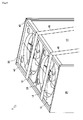
- belt supporting pads as one embodiment of the reinforcing material according to the present invention will be descried in detail with reference to Fig. 3 .
- the belt supporting pads 40, 40 are disposed across the whole length in a longitudinal direction of the periphery of the top board 15 in the heat exchange chamber 10.
- each of two belt supporting pads is disposed at each of the upper portions of the front and back surfaces in one engine driven heat pump1.
- the belt supporting pad 40 is formed of the material having rigidity without the deformation and distortion even due to some load.
- the belt supporting pads 40, 40 of the present embodiment are formed of stainless steel having board thickness larger than the outer plate 25 or a frame 21.
- the belt supporting pads 40, 40 are constructed so as to project outward of the top board 15, (upward in the drawing) in the longitudinal direction of the engine driven heat pump 1 (in this regard, except the outer plates 25 on both ends). In other words, the upper surfaces of belt supporting pads 40, 40 become the upmost surface, in the longitudinal direction of the engine driven heat pump 1. Incidentally, the belt supporting pads 40, 40 are fixed to the outer plate 25 and/or the frame 21 at a sufficient intensity by fastening material such as a bolt (not shown).
- the belt supporting pads 40, 40 can receive the belts 45 (see Fig. 3 ).
- the engine driven heat pump 1 is tightly fixed to the truck box by the sling using the belts 45, 45 or the like, so as to prevent the collapse of cargo.
- the belt supporting pads 40, 40 can receive the load due to the sing using the belts 45, 45 in this case.
- the engine driven heat pump 1 can be slung, without using particular packaging materials such as the polystyrene foam conventionally used for the sling as the protective materials. Consequently, working process during the delivery can be reduced.
- the belt supporting pads 40, 40 are provided as the reinforcing material, across the whole length in a longitudinal direction of the periphery of the top board 15, i.e., across the whole length in a width direction of the engine driven heat pump 1, and the fan shrouds 30, 30 are incorporated into the air conditioner, so that belt supporting portions during the packaging can be freely selected.
- the air conditioner according to the present invention is applicable in the air conditioner having the top blown ventilating construction.
Landscapes
- Engineering & Computer Science (AREA)
- Mechanical Engineering (AREA)
- General Engineering & Computer Science (AREA)
- Chemical & Material Sciences (AREA)
- Combustion & Propulsion (AREA)
- Life Sciences & Earth Sciences (AREA)
- Sustainable Development (AREA)
- Other Air-Conditioning Systems (AREA)
- Structures Of Non-Positive Displacement Pumps (AREA)
Abstract
The problem to be solved by the present invention is to provide an air conditioner that can be transported without a packaging material. An engine driven heat pump 1, which has a top blown ventilating construction and two device chambers vertically separated (a heat exchange chamber 10 and an equipment chamber 20), comprises fan shrouds 30, 30 provided so as to project from a top board 15 of the an engine driven heat pump 1 into the engine driven heat pump 1 and belt supporting pads 40, 40 provided across each of the whole lengths in a longitudinal direction of the periphery of the top board 15 as a reinforcing material. The fan shrouds 30, 30 are formed by integral moulding using resin together with the top board 15, and each of reinforcing boards 31, 31 is fixed to and wound around each of the outer peripheral edges around opening portions (lower end portions) of the fan shrouds 30, 30 directed toward the inside of the heat exchange chamber 10.
Description
- The present invention relates to a structural technology of an air conditioner having a top-blown ventilation construction.
- Conventionally, there is well known a fan shroud formed around a fan in an air conditioner. The fan shroud is a guide formed so as to introduce a blown air to one direction.
For example, as one example of the air conditioner, there is well known a top-blown air conditioner that inhales an ambient air from the side thereof so as to blast it out toward a top board thereof. In such a top-blown air conditioner, there is commonly used a fan shroud, which an opening end of an air outlet of the top board is formed so as to be projected upward, i.e., outside of the air conditioner.
Meanwhile, as disclosed inJP 1998-89726 - When the air conditioner is transported by a truck during the shipment from a factory or during the delivery to a customer, it is slung into a truck box using a belt or the like, so as to prevent it from being dropped and fell down. In this case, the air conditioner is slung and tightly fixed into the truck box, so as to prevent a collapse of cargo.
In this regard, the air conditioner, which the fan shroud thereof is formed so as to be projected outside of the air conditioner, is provided at the upper portion thereof with particular packaging materials made from lumber or the like and having a concave shape corresponding to a convex portion by the fan shroud, so that the top board and the fan shroud thereof is not damaged due to the load by the sling. The air conditioner is slung so as not to cover the fan shroud and transported. In the air conditioner at which the fan shroud disclosed inJP 1998-89726
However, it takes a lot of time for attaching and detaching these packaging materials.
In this regard, the problem so as to be solved by the present invention is to provide an air conditioner that can be transported without the packaging materials. - In an air conditioner of the present invention, which is an air conditioner having a top blown ventilating construction, fan shrouds are provided so that they are projected from a top board of the air conditioner therein and wherein the top board is provided across the longitudinal direction of the periphery thereof with a reinforcing material.
Due to the above construction, the air conditioner can be approximately constructed as an rectangular solid, and it is provided at belt supporting portions that support belts or the like used for fixing during the packaging therein with belt supporting pads as a reinforcing material, so that packaging materials are unnecessary during the delivery of the air conditioner. Belt supporting pads are provided as the reinforcing material, across the whole length in a longitudinal direction of the periphery of the top board, i.e., across the whole length in a width direction of the air conditioner, and the fan shrouds are incorporated into the air conditioner, so that belt supporting portions during the packaging can be freely selected. The height of the outdoor heat exchanger can be increased by the portions at which the fan shrouds are projected outside of the air conditioner, whereby heat exchange capacity of the air conditioner can be increased, in comparison to the conventional air conditioner having the same height as the air conditioner of the present invention. - In the present invention, as the fan shrouds are made from resin, and it is wound around an opening portion therein with a reinforcing board.
Due to the above construction, as the fan shrouds are made from resin, mass production can be efficiently performed. As the fan shrouds are made from resin, rigidity of the fan shrouds is decreased, but deformation due to lack of the rigidity can be minimized, by reinforcing the periphery of the fan shrouds using a reinforcing board. Accordingly, the clearance between the fan and the fan shroud can be minimized, so that air volume efficiency can be improved. -
-
Fig. 1 is a front view illustrating an entire construction of an engine driven heat pump according to an embodiment of the present invention. -
Fig. 2 is a perspective view illustrating a construction of a fan shroud according to an embodiment of the present invention. -
Fig. 3 is a perspective view illustrating belt supporting pads according to an embodiment of the present invention. - Hereinafter, an engine driven heat pump 1 as an embodiment of an air conditioner according to the present invention will be bricfly described, with reference to
Fig. 1 .
As shown inFig. 1 , the engine driven heat pump 1 is comprised of two device chambers vertically separated. The upper device chamber is aheat exchange chamber 10, and the lower one is anequipment chamber 20.
Theheat exchange chamber 10 is a device chamber having a construction capable of ventilating an ambient air for exchanging heats inoutdoor heat exchangers top board 15. Theheat exchange chamber 10 is provided with theoutdoor heat exchangers fans electric motors - The
outdoor heat exchangers heat exchange chamber 10. Thefans heat exchange chamber 10, and are driven by the fanelectric motors electric motors fans heat exchange chamber 10 in the present embodiment. The ambient air, which is inhaled from the front and back surfaces of theheat exchange chamber 10 by driving thefans outdoor heat exchangers
In this regard, the ventilation construction, by which the ambient air inhaled through theoutdoor heat exchangers fans top board 15 arranged at the top surface side of the engine driven heat pump 1, is a construction referred to as so-called "top blown ventilation construction", which is heavily used in large size air conditioners. - The
equipment chamber 20 is an approximately hermetically sealed device chamber that communicates with the outside only through a ventilating opening (not shown), an engine intake pipe (not shown) and an engine exhaust pipe (not shown). Theequipment chamber 20 is constructed so that the periphery of the side surface thereof is covered with anouter plate 25. Theequipment chamber 20 is arranged therein with major equipments of the engine driven heat pump 1 such as engine system equipments, refrigerant circuit equipments and an electric panel box (all of them are not shown). Anengine 22 and associated compartments or the like are arranged as the engine system equipment. A compressor and a reservoir (both of them are not shown) or the like arranged as refrigerant circuit equipment.
As described above, the engine driven heat pump 1 as one example of the air conditioner according to the present invention are provided therein with theheat exchange chamber 10 and thedevice chamber 20, and includes the top blown ventilating construction that blasts out the ambient air inhaled in theheat exchange chamber 10 upward. - Hereinafter, a fan shroud 30 as one example of the fan shroud according to the present invention will be described in detail, with reference to
Fig. 2 .
Incidentally, inFig. 2 , to explain clearly, each one of one or more (two in the present embodiment)fans electric motors fan shrouds outer plate 25, the fan electric motor mounting member, aftermentionedbelt supporting pad 40 or the like are omitted. - As shown in
Fig. 2 , thefan shroud 30 is an approximately cylindrical ventilating guide disposed around thefan 12, so as to introduce the ventilation by thefan 12 to one direction. As mentioned above, the ventilation in theheat exchange chamber 10 of the present embodiment is constructed so that it passes from the side of the fanelectric motor 13 through the inside of thefan shroud 30 to the outside of the engine driven heat pump 1, by driving the fan 12 (seeFig. 2 ). - The
fan shroud 30 of the present embodiment is provided so as to project from the inner surface (the lower surface) of thetop board 15 into the engine driven heat pump 1 (more strictly, into the heat exchange chamber 10).
Thefan shroud 30 of the present embodiment is formed by an integral moulding (for example, an injection moulding or the like) using resin having sufficient thermal resistance such as epoxy resin, synthetic resin, together with thetop board 15. In thefan shroud 30, a reinforcingboard 31 is wound around the outer peripheral edge an opening portion, at the inner end portion of the engine driven heat pump 1 (at the upstream side of the ventilating construction). The reinforcingboard 31 is one embodiment of a reinforcing board according to the present invention, and is made from a metal having high rigidity. The reinforcingboard 31 has ring geometry with thin board thickness, and is attached to the outer peripheral portion of the lower end of thefan shroud 30 at a sufficient intensity.
In this regard, the height of the reinforcingboard 31 is significantly lower than that of thefan shroud 30, and it is not especially limited in the present embodiment. - As seen from the above, the fan shroud 30 as one embodiment of the fan shroud according to the present invention is an approximately cylindrically-structured member, and is provided so as to project from the inner surface (the lower surface) of the
top board 15 into the engine driven heat pump 1 (more strictly, into the heat exchange chamber 10). Thefan shroud 30 is formed by the integral moulding using resin, and is made from the metal having high rigidity at the outer periphery of the opening portion (the lower end) thereof. Thefan shroud 30 is wound by the reinforcingboard 31 having ring geometry with thin board thickness in a circumferential direction.
Thus, thefan shroud 30 having complicated shapes is made from resin by the integral moulding, so that it can be efficiently produced in large quantities.
In the present embodiment, the reinforcingboard 31 is disposed at the periphery of the lower end of thefan shroud 30, i.e., at the upstream side of the ventilating construction of the engine driven heat pump 1, thereby being able to improve the rigidity of thefan shroud 30 made from resin. - Herein, it is generally known that as a clearance between the
fan shroud 30 and thefan 12 is smaller, air volume efficiency is better. However, there is a high possibility that thefan shroud 30 interferes with thefan 12, even due to the minimal deformity of thefan shroud 30, as the clearance is smaller.
Therefore, as described above, the reinforcingboard 31 is attached to the end portion of thefan shroud 30 in theheat exchange chamber 10, i.e., to the periphery of the opening portion thereof, whereby the rigidity of thefan shroud 30 can be enhanced so as to restrain the deformation such as the stress deformation and heat deformation. In other words, even when thefan shroud 30 made from resin is utilized, the clearance between thefan shroud 30 and thefan 12 can be practicably minified, thereby being able to improve the air volume efficiency. - In comparison to the conventional engine driven heat pump 1 in which the fan shrouds 30, 30 are projected outside of the
heat exchange chamber 10, the height of theheat exchange chamber 10 can be increased by the projected portions of the fan shrouds 30, 30. Briefly, heat exchange capacity can be increased, by heightening theheat exchangers heat exchangers - Hereinafter, belt supporting pads as one embodiment of the reinforcing material according to the present invention will be descried in detail with reference to
Fig. 3 .
As shown inFig. 3 , thebelt supporting pads top board 15 in theheat exchange chamber 10. In other words, each of two belt supporting pads is disposed at each of the upper portions of the front and back surfaces in one engine driven heat pump1. Thebelt supporting pad 40 is formed of the material having rigidity without the deformation and distortion even due to some load. For example, thebelt supporting pads outer plate 25 or a frame 21.
Thebelt supporting pads top board 15, (upward in the drawing) in the longitudinal direction of the engine driven heat pump 1 (in this regard, except theouter plates 25 on both ends). In other words, the upper surfaces ofbelt supporting pads belt supporting pads outer plate 25 and/or the frame 21 at a sufficient intensity by fastening material such as a bolt (not shown). - Due to the above construction, when the engine driven heat pump 1 is slung, the
belt supporting pads Fig. 3 ).
As shown inFig. 3 , in general, the engine driven heat pump 1 is tightly fixed to the truck box by the sling using thebelts belt supporting pads belts - In other words, the engine driven heat pump 1 can be slung, without using particular packaging materials such as the polystyrene foam conventionally used for the sling as the protective materials. Consequently, working process during the delivery can be reduced.
Thebelt supporting pads top board 15, i.e., across the whole length in a width direction of the engine driven heat pump 1, and the fan shrouds 30, 30 are incorporated into the air conditioner, so that belt supporting portions during the packaging can be freely selected. - The air conditioner according to the present invention is applicable in the air conditioner having the top blown ventilating construction.
Claims (2)
- An air conditioner having a top-blown ventilation construction, wherein fan shrouds are provided so that they are projected from a top board of the air conditioner therein and wherein the top board is provided across the longitudinal direction of the periphery thereof with a reinforcing material.
- The air conditioner as set forth in claim 1, wherein the fan shrouds are made from resin and wherein the reinforcing board is provided at the periphery of an opening portion in the air conditioner.
Applications Claiming Priority (2)
| Application Number | Priority Date | Filing Date | Title |
|---|---|---|---|
| JP2007041341A JP2008202890A (en) | 2007-02-21 | 2007-02-21 | Air conditioning device |
| PCT/JP2008/052835 WO2008102797A1 (en) | 2007-02-21 | 2008-02-20 | Air conditioner |
Publications (1)
| Publication Number | Publication Date |
|---|---|
| EP2113724A1 true EP2113724A1 (en) | 2009-11-04 |
Family
ID=39710071
Family Applications (1)
| Application Number | Title | Priority Date | Filing Date |
|---|---|---|---|
| EP08711641A Withdrawn EP2113724A1 (en) | 2007-02-21 | 2008-02-20 | Air conditioner |
Country Status (5)
| Country | Link |
|---|---|
| EP (1) | EP2113724A1 (en) |
| JP (1) | JP2008202890A (en) |
| KR (1) | KR20090103944A (en) |
| CN (1) | CN101627262A (en) |
| WO (1) | WO2008102797A1 (en) |
Cited By (1)
| Publication number | Priority date | Publication date | Assignee | Title |
|---|---|---|---|---|
| EP3034888A4 (en) * | 2013-12-16 | 2016-08-17 | Mitsubishi Heavy Ind Ltd | BLOWER |
Family Cites Families (3)
| Publication number | Priority date | Publication date | Assignee | Title |
|---|---|---|---|---|
| JPS6241144Y2 (en) * | 1980-04-01 | 1987-10-21 | ||
| JPH0638253Y2 (en) * | 1988-03-31 | 1994-10-05 | アイシン精機株式会社 | Frame of outdoor unit for air conditioning |
| JP2526412Y2 (en) * | 1989-09-14 | 1997-02-19 | カルソニック株式会社 | Motor fan unit for heat exchanger |
-
2007
- 2007-02-21 JP JP2007041341A patent/JP2008202890A/en active Pending
-
2008
- 2008-02-20 KR KR1020097017086A patent/KR20090103944A/en not_active Ceased
- 2008-02-20 WO PCT/JP2008/052835 patent/WO2008102797A1/en not_active Ceased
- 2008-02-20 EP EP08711641A patent/EP2113724A1/en not_active Withdrawn
- 2008-02-20 CN CN200880005536A patent/CN101627262A/en active Pending
Non-Patent Citations (1)
| Title |
|---|
| See references of WO2008102797A1 * |
Cited By (1)
| Publication number | Priority date | Publication date | Assignee | Title |
|---|---|---|---|---|
| EP3034888A4 (en) * | 2013-12-16 | 2016-08-17 | Mitsubishi Heavy Ind Ltd | BLOWER |
Also Published As
| Publication number | Publication date |
|---|---|
| CN101627262A (en) | 2010-01-13 |
| JP2008202890A (en) | 2008-09-04 |
| KR20090103944A (en) | 2009-10-01 |
| WO2008102797A1 (en) | 2008-08-28 |
Similar Documents
| Publication | Publication Date | Title |
|---|---|---|
| EP2711640B1 (en) | Outdoor unit for refrigeration device | |
| CN104520649B (en) | Outdoor unit of refrigeration cycle plant | |
| AU2016396507B2 (en) | Air conditioner and blower device | |
| US20150040609A1 (en) | Outdoor unit of air conditioner | |
| EP2384109A1 (en) | Heat exchanger device and heating element holder using same | |
| KR101156293B1 (en) | Air conditioner indoor unit | |
| US8881543B2 (en) | Duct type air conditioner | |
| US9249984B2 (en) | Base pan | |
| US8973388B2 (en) | Duct type air conditioner | |
| EP2930441A1 (en) | Outdoor machine for air-conditioner | |
| US20220299214A1 (en) | Outdoor unit for air-conditioning apparatus and method for assembling outdoor unit for air-conditioning apparatus | |
| KR20090083737A (en) | Outdoor unit for air conditioner | |
| JP2011007364A (en) | Air conditioner | |
| CN109084383B (en) | Air conditioner outdoor unit and air conditioner having the same | |
| KR20090103944A (en) | Air conditioner | |
| CN205957349U (en) | Outdoor machine | |
| EP3567324B1 (en) | Hvacr system including multi-positional and multi-use plenum fans | |
| US10465923B2 (en) | Support system and methods for HVAC systems | |
| JP2004218514A (en) | Air compressor | |
| JPWO2020075243A1 (en) | Outdoor unit of air conditioner | |
| JP2007071517A (en) | Air conditioner outdoor unit and air conditioner | |
| CN116326228A (en) | Fan assembly, power supply equipment and method for manufacturing power supply equipment | |
| CN207865564U (en) | A kind of air-conditioner outdoor unit | |
| CN222210577U (en) | Outdoor unit | |
| CN217348763U (en) | Packaging frame and electric appliance packaging assembly |
Legal Events
| Date | Code | Title | Description |
|---|---|---|---|
| PUAI | Public reference made under article 153(3) epc to a published international application that has entered the european phase |
Free format text: ORIGINAL CODE: 0009012 |
|
| 17P | Request for examination filed |
Effective date: 20090921 |
|
| AK | Designated contracting states |
Kind code of ref document: A1 Designated state(s): AT BE BG CH CY CZ DE DK EE ES FI FR GB GR HR HU IE IS IT LI LT LU LV MC MT NL NO PL PT RO SE SI SK TR |
|
| DAX | Request for extension of the european patent (deleted) | ||
| STAA | Information on the status of an ep patent application or granted ep patent |
Free format text: STATUS: THE APPLICATION IS DEEMED TO BE WITHDRAWN |
|
| 18D | Application deemed to be withdrawn |
Effective date: 20110830 |