EP2113459B1 - Door actuator mounted to an aft portion of an air inlet duct - Google Patents
Door actuator mounted to an aft portion of an air inlet duct Download PDFInfo
- Publication number
- EP2113459B1 EP2113459B1 EP09158283.3A EP09158283A EP2113459B1 EP 2113459 B1 EP2113459 B1 EP 2113459B1 EP 09158283 A EP09158283 A EP 09158283A EP 2113459 B1 EP2113459 B1 EP 2113459B1
- Authority
- EP
- European Patent Office
- Prior art keywords
- door
- actuator
- inlet
- inlet duct
- aft
- Prior art date
- Legal status (The legal status is an assumption and is not a legal conclusion. Google has not performed a legal analysis and makes no representation as to the accuracy of the status listed.)
- Not-in-force
Links
- 230000007246 mechanism Effects 0.000 claims description 7
- 230000008878 coupling Effects 0.000 claims description 5
- 238000010168 coupling process Methods 0.000 claims description 5
- 238000005859 coupling reaction Methods 0.000 claims description 5
- 230000003116 impacting effect Effects 0.000 claims description 2
- 239000003570 air Substances 0.000 description 24
- 238000001816 cooling Methods 0.000 description 3
- 238000012423 maintenance Methods 0.000 description 3
- 239000012080 ambient air Substances 0.000 description 2
- 230000000694 effects Effects 0.000 description 2
- 238000011084 recovery Methods 0.000 description 2
- 230000000712 assembly Effects 0.000 description 1
- 238000000429 assembly Methods 0.000 description 1
- 238000004891 communication Methods 0.000 description 1
- 230000003750 conditioning effect Effects 0.000 description 1
- 230000009977 dual effect Effects 0.000 description 1
- 230000007613 environmental effect Effects 0.000 description 1
- 238000009434 installation Methods 0.000 description 1
- 239000000463 material Substances 0.000 description 1
- 230000004048 modification Effects 0.000 description 1
- 238000012986 modification Methods 0.000 description 1
- 230000009467 reduction Effects 0.000 description 1
- 230000008439 repair process Effects 0.000 description 1
- 239000007858 starting material Substances 0.000 description 1
Images

Classifications
-
- B—PERFORMING OPERATIONS; TRANSPORTING
- B64—AIRCRAFT; AVIATION; COSMONAUTICS
- B64D—EQUIPMENT FOR FITTING IN OR TO AIRCRAFT; FLIGHT SUITS; PARACHUTES; ARRANGEMENT OR MOUNTING OF POWER PLANTS OR PROPULSION TRANSMISSIONS IN AIRCRAFT
- B64D41/00—Power installations for auxiliary purposes
-
- B—PERFORMING OPERATIONS; TRANSPORTING
- B64—AIRCRAFT; AVIATION; COSMONAUTICS
- B64D—EQUIPMENT FOR FITTING IN OR TO AIRCRAFT; FLIGHT SUITS; PARACHUTES; ARRANGEMENT OR MOUNTING OF POWER PLANTS OR PROPULSION TRANSMISSIONS IN AIRCRAFT
- B64D33/00—Arrangement in aircraft of power plant parts or auxiliaries not otherwise provided for
- B64D33/02—Arrangement in aircraft of power plant parts or auxiliaries not otherwise provided for of combustion air intakes
-
- B—PERFORMING OPERATIONS; TRANSPORTING
- B64—AIRCRAFT; AVIATION; COSMONAUTICS
- B64D—EQUIPMENT FOR FITTING IN OR TO AIRCRAFT; FLIGHT SUITS; PARACHUTES; ARRANGEMENT OR MOUNTING OF POWER PLANTS OR PROPULSION TRANSMISSIONS IN AIRCRAFT
- B64D33/00—Arrangement in aircraft of power plant parts or auxiliaries not otherwise provided for
- B64D33/02—Arrangement in aircraft of power plant parts or auxiliaries not otherwise provided for of combustion air intakes
- B64D2033/0213—Arrangement in aircraft of power plant parts or auxiliaries not otherwise provided for of combustion air intakes specially adapted for auxiliary power units (APU's)
Definitions
- the present invention relates to aircraft inlet doors, and more particularly, the actuation of inlet doors of an auxiliary power unit.
- Auxiliary power units are used in aircraft to provide electrical power and compressed air to various aircraft systems and components.
- APU can power the environmental control systems, air drive hydraulic pumps, and the starters for the engines.
- the APU may provide pneumatic and/or electric power to the aircraft.
- APUs are located in the aft section of the aircraft, at or near the tailcone section and include inlet and exhaust ducting that exit through an opening, or cut-out, in the aircraft fuselage to allow sufficient air flow through to the APU.
- a RAM air door is typically provided to protect the APU from foreign object damage when not in use and/or during ground movement, and to maximize airflow into the APU when performance or oil cooling at altitude is required.
- the RAM air door opens, either on the ground or in flight.
- the RAM air door is configured to open approximately 20-45 degrees during a flight phase of operation and in many cases approximately 70 degrees, or fully open, such as during a ground phase of operation full open (70 degrees) on ground, relative to the aircraft fuselage. This allows for noise reduction on the ground, while optimizing RAM recover for the APU performance in flight with minimal drag to the aircraft.
- the actuation of the RAM air door is achieved by mounting an actuating device proximate the RAM air door.
- the actuator is mounted to an interior surface of the inlet duct and coupled to the side or front of the inlet door.
- the positioning and mounting location of the actuator may affect aerodynamic performance of the door and may affect acoustic treatment performance of the inlet duct.
- the actuator, and more particularly the actuator rod may extend into the flow of air in the inlet duct disrupting the aerodynamic performance.
- the mounting location of the actuator may impact accessibility of the actuator for maintenance, repair and replacement purposes.
- US patent 4 418 879 is considered the closest known state of the art and describes an air inlet and scoop for aircraft auxiliary power units which aim to overcome problems starting or operating auxiliary power units during flight because of thick boundary layers on the aft body of the aircraft.
- US application 11/299 116 teaches a dual action inlet door for use with an auxiliary power unit of an aircraft in which does not enhance noise propagation in a forwards direction.
- a RAM air door actuator that minimizes disruption to the aerodynamic performance of the RAM air inlet door to which it is coupled and minimizes acoustic treatment performance on the inlet duct.
- a RAM air door actuator that provides maintenance access from inside the APU compartment for the purpose of repairing and/or replacing the actuator. The present invention addresses one or more of these needs.
- the present invention according to claim 1 provides an inlet door system providing RAM air to an auxiliary power unit (APU) contained within an aircraft.
- APU auxiliary power unit
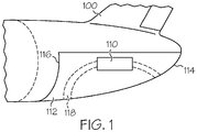
- FIG. 1 a cross-sectional schematic of an auxiliary power unit (APU) 110 is shown mounted in the tailcone of an aircraft 100.
- the aircraft 100 includes a compartment 112 that is defined by the aircraft exterior surfaces 114 and a firewall 116.
- the exterior surface 114 includes an intake opening 118 that communicates with the APU 110 via an inlet duct 120 (shown in FIG. 2 ).
- the inlet duct 120 and intake opening 118 are shown positioned on the underside of the aircraft 100, it will be appreciated that both may be located anywhere on the aircraft 100 depending on the aircraft configuration.
- the firewall 116 separates the compartment 112 from the rest of the aircraft fuselage.
- the APU 110 is disposed within the compartment 112.
- an inlet door system 109 and more particularly an inlet duct portion of the exemplary gas turbine APU 110 of FIG. 1 .
- the inlet duct 120 includes an inlet port 122, an outlet port 124, and a sidewall 126 that defines a flow passage 128 through which the air passes and an inlet door assembly 130 that is mounted thereon.
- the amount of air that is ingested is controlled by the inlet door assembly 30.
- the inlet door assembly 130 also controls the direction of noise that propagates from the APU 110 to the ambient environment.
- the inlet door assembly 130 is depicted and is coupled to the inlet duct 120.
- the inlet door assembly 130 generally includes a door 132 coupled to an aft inlet duct mounted door actuator 134.
- the door 132 preferably includes first and second sides or ends 136, 137 and a seal 138 that is configured to sealingly couple the door 132 to an inlet opening 140 when the door 132 is in a closed position.
- the door 132 is coupled to the inlet duct 120, such that at least a portion of the door 132 is rotatable between at least two positions, for example, a first position and a second position.
- the door 132 is rotatable so that sufficient ambient air is allowed into the inlet duct air flow passage 128 when desired, while APU noise is reduced.
- the door 132 is rotationally mounted to the aft inlet duct mounted door actuator 134.
- the door 132 may be mounted to the outlet port 122, a sidewall 142 of the inlet duct 120, such as by rotationally mounting the door 132 to an exterior surface of the inlet duct 120, or mounted to the aircraft 100.
- the aft inlet duct mounted door actuator 134 is configured to move the door 132 between a first or closed position as best illustrated in FIGs.
- the aft inlet duct mounted door actuator 134 may be configured to first raise the door 132 away from the aircraft exterior surface 114 and then rotate the door 132.
- the aft inlet duct mounted door actuator 134 may be any type of commonly known actuator capable of moving the door 132 depending on the inlet door assembly configuration.
- the aft inlet duct mounted door actuator 134 may be a linear or rotary actuator.
- the inlet door assembly 130 includes a structural bracket 148 that may be formed separately from the inlet duct 120 or formed integral therewith.
- the structural bracket 148 provides structural support for the mounting of the aft inlet duct mounted door actuator 134 to an exterior surface 147 of an aft portion 149 of the inlet duct 120.
- the inlet door assembly 130 further includes a compartment cooling duct 144 and an optional fire proof cover 146 positioned to substantially enclose the aft inlet duct mounted door actuator 134.
- the inlet door assembly 130 includes the aft inlet duct mounted door actuator 134 coupled to the door first side 136.
- a coupling mechanism 150 such as a screw, clamp, or other type of mechanism is configured to rotationally couple the door 132 to the aft inlet duct mounted door actuator 134.
- the aft inlet duct mounted door actuator 134 may include an aft lever arm 152 formed at a distal end of an actuator extension rod 154, to which the door 132 is coupled via the coupling mechanism 150.
- the aft inlet duct mounted door actuator 134 is in communication, either electrically, pneumatically, or hydraulically, with a control circuit, an electronic control unit (ECU), or any one of numerous other types of control mechanisms (not shown) that are configured to communicate door position commands to the aft inlet duct mounted door actuator 134.
- the aft lever arm 152 is in the form of a forked component that provides symmetrical door loading during opening and closing of the door 132.
- the door second side 137 preferably rotates between 0 degrees and +90 degrees, relative to the aircraft exterior surface so that sufficient ambient air is allowed into the inlet duct air flow passage 128 when desired, while APU noise is reduced.
- the aft inlet duct mounted door actuator 134 operates by pushing and pulling on the extension rod 154 in conjunction with the aft lever arm 152 to rotationally open and close the door 132.
- the mounting of the aft inlet duct mounted door actuator 134 on the aft portion 149 of the inlet duct 120 thereby permits the actuator extension rod 154 to operate without obstructing the inlet duct air flow passage 128 and impacting aero dynamic performance.
- the mounting of the aft inlet duct mounted door actuator 134 on the aft portion 149 of the inlet duct 120 provides for the aft inlet duct mounted door actuator 134 to be readily accessible via the APU compartment 112 for maintenance and/or replacement.
- FIGs. 3 and 5 illustrate the door 132 of the inlet door assembly 130 in a closed position and FIGs. 4 and 6 illustrate the door 132 in an open position.
- the closed position is typically used while the APU is not in operation, and the full-open position is typically used while the aircraft is on the ground and allows noise to propagate directly out of the inlet duct 120 minimizing deflection forward the aircraft, the door is in an intermediate open position in flight to provide a RAM effect for APU inlet recovery and APU compartment cooling.
- the control circuit (not shown) communicates the desired position to the aft inlet duct mounted door actuator 134, which then actuates the door 132 to a desired angle "x" relative to the aircraft exterior surface 114 (see FIG.
- the outward position may be used to achieve RAM air recovery while minimizing aircraft drag when the aircraft is in flight. Additionally, when the aircraft is taxiing on the ground, the outer surface of the door 132 acts as a shield to deflect foreign objects from the inlet duct 120 and prevent damage thereto.
- the inlet duct 120 When the APU is not operating, such as during portions of flight, the inlet duct 120 is closed, as shown in FIGs. 3 and 5 .
- the door 132 is preferably in a closed position to lower aircraft drag.
- the control circuit (not shown) communicates to the aft inlet duct mounted door actuator 134 to close the door 132 by causing the door second side 137 to rotate until the door 132 is flush against the aircraft exterior surface 114.
- the door 132 and the inlet duct 120 sealingly couple to one another so that foreign objects do not enter into the inlet duct 120 to damage the APU.
- the mounting of the aft inlet duct mounted door actuator 134 to the exterior surface 147 of the aft portion 149 of the inlet duct 120 allows for access to the aft inlet duct mounted door actuator 134 from inside the APU compartment 112.
- positioning of the aft inlet duct mounted door actuator 134 on the aft portion of the inlet duct 120 minimizes the door frame cut-out in the aircraft exterior surface, as compared to a side actuated door.
- an improved inlet door assembly is configured to provide for aft inlet duct mounting of the door actuator 134.
- the mounting of the aft inlet duct mounted door actuator 134 on the exterior surface 147 of the aft portion 149 of the inlet duct 120 minimizes any impact on aerodynamic performance of the door.
- the actuator 134 is mounted on the exterior surface 147 of the aft portion 149 of the inlet duct it does not impact the inlet duct air flow passage 128, and thereby minimizes impact on the available acoustic area on the interior of the inlet duct 120.
- mounting the actuator 134 in this manner, it provides for accessibility to the actuator 134 via the APU compartment.
Landscapes
- Engineering & Computer Science (AREA)
- Aviation & Aerospace Engineering (AREA)
- Chemical & Material Sciences (AREA)
- Combustion & Propulsion (AREA)
- Structures Of Non-Positive Displacement Pumps (AREA)
- Air-Flow Control Members (AREA)
- Transmission Devices (AREA)
Description
- The present invention relates to aircraft inlet doors, and more particularly, the actuation of inlet doors of an auxiliary power unit.
- Auxiliary power units ("APU") are used in aircraft to provide electrical power and compressed air to various aircraft systems and components. When an aircraft is on the ground, its main source of electrical power and cabin conditioning comes from the APU. In particular, the APU can power the environmental control systems, air drive hydraulic pumps, and the starters for the engines. When an aircraft is in flight, the APU may provide pneumatic and/or electric power to the aircraft.
- Typically, APUs are located in the aft section of the aircraft, at or near the tailcone section and include inlet and exhaust ducting that exit through an opening, or cut-out, in the aircraft fuselage to allow sufficient air flow through to the APU. For aircraft on which APUs operate during flight, a RAM air door is typically provided to protect the APU from foreign object damage when not in use and/or during ground movement, and to maximize airflow into the APU when performance or oil cooling at altitude is required. Thus, when the APU is running, the RAM air door opens, either on the ground or in flight. Typically in such configuration, the RAM air door is configured to open approximately 20-45 degrees during a flight phase of operation and in many cases approximately 70 degrees, or fully open, such as during a ground phase of operation full open (70 degrees) on ground, relative to the aircraft fuselage. This allows for noise reduction on the ground, while optimizing RAM recover for the APU performance in flight with minimal drag to the aircraft.
- In many conventional aircraft types, the actuation of the RAM air door is achieved by mounting an actuating device proximate the RAM air door. In most instances, the actuator is mounted to an interior surface of the inlet duct and coupled to the side or front of the inlet door. The positioning and mounting location of the actuator may affect aerodynamic performance of the door and may affect acoustic treatment performance of the inlet duct. In many instances, the actuator, and more particularly the actuator rod, may extend into the flow of air in the inlet duct disrupting the aerodynamic performance. In addition, the mounting location of the actuator may impact accessibility of the actuator for maintenance, repair and replacement purposes.
US patent 4 418 879 is considered the closest known state of the art and describes an air inlet and scoop for aircraft auxiliary power units which aim to overcome problems starting or operating auxiliary power units during flight because of thick boundary layers on the aft body of the aircraft.US application 11/299 116 - Therefore, there is a need for a RAM air door actuator that minimizes disruption to the aerodynamic performance of the RAM air inlet door to which it is coupled and minimizes acoustic treatment performance on the inlet duct. In addition, there is a need for a RAM air door actuator that provides maintenance access from inside the APU compartment for the purpose of repairing and/or replacing the actuator. The present invention addresses one or more of these needs.
- The present invention according to claim 1 provides an inlet door system providing RAM air to an auxiliary power unit (APU) contained within an aircraft.
- Other independent features and advantages of the preferred inlet door assembly will become apparent from the following detailed description, taken in conjunction with the accompanying drawings which illustrate, by way of example, the principles of the invention.
-
-
FIG. 1 is a cross-sectional schematic showing an auxiliary power unit (APU) mounted in the tailcone of an airplane; -
FIG. 2 is a perspective view of the inlet duct portion of an exemplary gas turbine APU; -
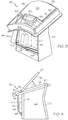
FIG. 3 is a perspective rear view of the APU inlet duct having an inlet door assembly mounted thereon, including an exemplary aft inlet duct mounted actuator; -
FIG. 4 is a schematic sectional view of the APU inlet duct having the exemplary aft inlet duct mounted actuator ofFIG. 2 mounted thereon; -
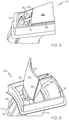
FIG. 5 is a perspective view of a portion of the inlet door assembly shown in a closed position and including the exemplary aft inlet duct mounted actuator; and -
FIG. 6 is a perspective view of a portion of the inlet door assembly shown in an open position and including the exemplary aft inlet duct mounted actuator. - Before proceeding with a detailed description of the various embodiments, it is to be appreciated that the air inlet assemblies described below may be used in conjunction with various types of gas turbine engines, such as an aircraft turbofan jet engine, and various types of aircrafts, watercrafts and ground-based installations. The skilled artisan will appreciate that, although the present invention is, for convenience of explanation, depicted and described as being implemented in the context of an auxiliary power unit, it will be appreciated that it can be implemented with other sections of an engine as well. Additionally, as used herein, like numerals refer to like parts.
- Turning now to the description and with reference first to
FIG. 1 , a cross-sectional schematic of an auxiliary power unit (APU) 110 is shown mounted in the tailcone of anaircraft 100. Theaircraft 100 includes acompartment 112 that is defined by the aircraftexterior surfaces 114 and afirewall 116. Theexterior surface 114 includes anintake opening 118 that communicates with the APU 110 via an inlet duct 120 (shown inFIG. 2 ). Although theinlet duct 120 andintake opening 118 are shown positioned on the underside of theaircraft 100, it will be appreciated that both may be located anywhere on theaircraft 100 depending on the aircraft configuration. Thefirewall 116 separates thecompartment 112 from the rest of the aircraft fuselage. The APU 110 is disposed within thecompartment 112. - With reference to
FIG. 2 , illustrated is aninlet door system 109, and more particularly an inlet duct portion of the exemplary gas turbine APU 110 ofFIG. 1 . Theinlet duct 120 includes aninlet port 122, anoutlet port 124, and asidewall 126 that defines aflow passage 128 through which the air passes and aninlet door assembly 130 that is mounted thereon. The amount of air that is ingested is controlled by the inlet door assembly 30. Theinlet door assembly 130 also controls the direction of noise that propagates from the APU 110 to the ambient environment. - Referring now to
FIGs. 3-6 the exemplaryinlet door assembly 130 is depicted and is coupled to theinlet duct 120. Theinlet door assembly 130 generally includes adoor 132 coupled to an aft inlet duct mounteddoor actuator 134. Thedoor 132 preferably includes first and second sides orends seal 138 that is configured to sealingly couple thedoor 132 to an inlet opening 140 when thedoor 132 is in a closed position. Thedoor 132 is coupled to theinlet duct 120, such that at least a portion of thedoor 132 is rotatable between at least two positions, for example, a first position and a second position. Thedoor 132 is rotatable so that sufficient ambient air is allowed into the inlet ductair flow passage 128 when desired, while APU noise is reduced. In the illustrated embodiment thedoor 132 is rotationally mounted to the aft inlet duct mounteddoor actuator 134. Alternatively, thedoor 132 may be mounted to theoutlet port 122, asidewall 142 of theinlet duct 120, such as by rotationally mounting thedoor 132 to an exterior surface of theinlet duct 120, or mounted to theaircraft 100. The aft inlet duct mounteddoor actuator 134 is configured to move thedoor 132 between a first or closed position as best illustrated inFIGs. 3 and5 , in which at least a portion of thedoor 132 deflects the APU air flow in a first direction, and a second or open position as best illustrated inFIGs. 4 and6 , in which at least a portion of thedoor 132 deflects the air flow in a second direction. Alternatively, the aft inlet duct mounteddoor actuator 134 may be configured to first raise thedoor 132 away from theaircraft exterior surface 114 and then rotate thedoor 132. The aft inlet duct mounteddoor actuator 134 may be any type of commonly known actuator capable of moving thedoor 132 depending on the inlet door assembly configuration. For instance, the aft inlet duct mounteddoor actuator 134 may be a linear or rotary actuator. - In this particular embodiment, the
inlet door assembly 130 includes astructural bracket 148 that may be formed separately from theinlet duct 120 or formed integral therewith. Thestructural bracket 148 provides structural support for the mounting of the aft inlet duct mounteddoor actuator 134 to anexterior surface 147 of anaft portion 149 of theinlet duct 120. The positioning of thestructural bracket 148 on theexterior surface 147 of theexterior aft portion 149 of theinlet duct 120 and mounting of the aft inlet duct mounteddoor actuator 134 thereto, minimizes any impact on the available acoustic area inside of theinlet duct 120 and any effect on the aerodynamic performance of the inlet system. Theinlet door assembly 130 further includes acompartment cooling duct 144 and an optionalfire proof cover 146 positioned to substantially enclose the aft inlet duct mounteddoor actuator 134. - In the embodiment depicted herein, the
inlet door assembly 130 includes the aft inlet duct mounteddoor actuator 134 coupled to the doorfirst side 136. Acoupling mechanism 150, such as a screw, clamp, or other type of mechanism is configured to rotationally couple thedoor 132 to the aft inlet duct mounteddoor actuator 134. More specifically, the aft inlet duct mounteddoor actuator 134 may include anaft lever arm 152 formed at a distal end of anactuator extension rod 154, to which thedoor 132 is coupled via thecoupling mechanism 150. The aft inlet duct mounteddoor actuator 134 is in communication, either electrically, pneumatically, or hydraulically, with a control circuit, an electronic control unit (ECU), or any one of numerous other types of control mechanisms (not shown) that are configured to communicate door position commands to the aft inlet duct mounteddoor actuator 134. In the illustrated embodiment, theaft lever arm 152 is in the form of a forked component that provides symmetrical door loading during opening and closing of thedoor 132. During actuation, the doorsecond side 137 preferably rotates between 0 degrees and +90 degrees, relative to the aircraft exterior surface so that sufficient ambient air is allowed into the inlet ductair flow passage 128 when desired, while APU noise is reduced. The aft inlet duct mounteddoor actuator 134 operates by pushing and pulling on theextension rod 154 in conjunction with theaft lever arm 152 to rotationally open and close thedoor 132. The mounting of the aft inlet duct mounteddoor actuator 134 on theaft portion 149 of theinlet duct 120 thereby permits theactuator extension rod 154 to operate without obstructing the inlet ductair flow passage 128 and impacting aero dynamic performance. In addition the mounting of the aft inlet duct mounteddoor actuator 134 on theaft portion 149 of theinlet duct 120 provides for the aft inlet duct mounteddoor actuator 134 to be readily accessible via theAPU compartment 112 for maintenance and/or replacement. - As noted above,
FIGs. 3 and5 illustrate thedoor 132 of theinlet door assembly 130 in a closed position andFIGs. 4 and6 illustrate thedoor 132 in an open position. The closed position is typically used while the APU is not in operation, and the full-open position is typically used while the aircraft is on the ground and allows noise to propagate directly out of theinlet duct 120 minimizing deflection forward the aircraft, the door is in an intermediate open position in flight to provide a RAM effect for APU inlet recovery and APU compartment cooling. When the open position is desired, the control circuit (not shown) communicates the desired position to the aft inlet duct mounteddoor actuator 134, which then actuates thedoor 132 to a desired angle "x" relative to the aircraft exterior surface 114 (seeFIG. 4 ). The outward position may be used to achieve RAM air recovery while minimizing aircraft drag when the aircraft is in flight. Additionally, when the aircraft is taxiing on the ground, the outer surface of thedoor 132 acts as a shield to deflect foreign objects from theinlet duct 120 and prevent damage thereto. - When the APU is not operating, such as during portions of flight, the
inlet duct 120 is closed, as shown inFIGs. 3 and5 . Thedoor 132 is preferably in a closed position to lower aircraft drag. When thedoor 132 is actuated from the open position shown inFIGs. 4 and6 to the closed position, the control circuit (not shown) communicates to the aft inlet duct mounteddoor actuator 134 to close thedoor 132 by causing the doorsecond side 137 to rotate until thedoor 132 is flush against theaircraft exterior surface 114. Most preferably, thedoor 132 and theinlet duct 120 sealingly couple to one another so that foreign objects do not enter into theinlet duct 120 to damage the APU. - As best illustrated in
FIGs. 3 ,5 and 6 , the mounting of the aft inlet duct mounteddoor actuator 134 to theexterior surface 147 of theaft portion 149 of theinlet duct 120 allows for access to the aft inlet duct mounteddoor actuator 134 from inside theAPU compartment 112. In addition, positioning of the aft inlet duct mounteddoor actuator 134 on the aft portion of theinlet duct 120 minimizes the door frame cut-out in the aircraft exterior surface, as compared to a side actuated door. - Thus, an improved inlet door assembly has been provided that is configured to provide for aft inlet duct mounting of the
door actuator 134. The mounting of the aft inlet duct mounteddoor actuator 134 on theexterior surface 147 of theaft portion 149 of theinlet duct 120 minimizes any impact on aerodynamic performance of the door. In addition, because theactuator 134 is mounted on theexterior surface 147 of theaft portion 149 of the inlet duct it does not impact the inlet ductair flow passage 128, and thereby minimizes impact on the available acoustic area on the interior of theinlet duct 120. Furthermore, by mounting theactuator 134 in this manner, it provides for accessibility to theactuator 134 via the APU compartment. - While the invention has been described with reference to a preferred embodiment, it will be understood by those skilled in the art that various changes may be made and equivalents may be substituted for elements thereof without departing from the scope of the claims. In addition, many modifications may be made to adapt to a particular situation or material to the teachings of the invention without departing from the scope of the claims. Therefore, it is intended that the invention not be limited to the particular embodiment disclosed as the best mode contemplated for carrying out this invention, but that the invention will include all embodiments falling within the scope of the appended claims.
Claims (4)
- An inlet door system (109) providing RAM air to an auxiliary power unit (APU (110)) and APU compartment (112) contained within an aircraft (100), the inlet door system (109) comprising:a duct (120) configured to extend from the auxiliary power unit (APU (110)) to an intake opening (118) formed in an outer surface of the aircraft (100), the duct (12) having an inlet port (122), an outlet port (124), and a duct sidewall (126) extending from the inlet port (122) to the outlet port (124), the duct sidewall (126) defining an air flow passage (128) therebetween the inlet port (122) and the outlet port (124);a structural bracket (148) on an exterior surface (147) of an aft portion (149) of the duct (120);a door (132) rotationally positioned to sealingly engage with the inlet port (122) and configured to selectively rotate between at least a first position and a second position,an actuator (134) rotationally coupled to the door (132) with an aft lever arm (152), and mounted to the structural bracket (148), the aft lever arm (152) including an actuator extension rod (154) having a first end coupled to the actuator (134) and a second end coupled to a door coupling mechanism (150), the actuator (134) configured to push and pull on the actuator extension rod (154) in conjunction with the aft lever arm (152) to thereby rotate the door (132) to at least the first position and the second position without the actuator extension rod obstructing the air flow passage (128), and impacting aerodynamic performance,wherein the door coupling mechanism (150) is a forked component configured to provide symmetrical door loading when coupled to the door (132).
- The inlet door system (109) of claim 1, wherein the actuator (134) is coupled to the actuator extension rod (154) and the door coupling mechanism (150) and configured to selectively raise and lower the door (132).
- The inlet door system (109) of claim 1, wherein the actuator (134) is a linear actuator.
- The inlet door system (109) of claim 1, wherein the actuator (134) is configured to selectively raise and lower the door (132) to deflect APU (110) noise within the air flow passage (128).
Applications Claiming Priority (1)
| Application Number | Priority Date | Filing Date | Title |
|---|---|---|---|
| US12/112,711 US8141816B2 (en) | 2008-04-30 | 2008-04-30 | AFT inlet duct mounted door actuator |
Publications (3)
| Publication Number | Publication Date |
|---|---|
| EP2113459A2 EP2113459A2 (en) | 2009-11-04 |
| EP2113459A3 EP2113459A3 (en) | 2015-12-02 |
| EP2113459B1 true EP2113459B1 (en) | 2018-06-06 |
Family
ID=40790661
Family Applications (1)
| Application Number | Title | Priority Date | Filing Date |
|---|---|---|---|
| EP09158283.3A Not-in-force EP2113459B1 (en) | 2008-04-30 | 2009-04-20 | Door actuator mounted to an aft portion of an air inlet duct |
Country Status (2)
| Country | Link |
|---|---|
| US (1) | US8141816B2 (en) |
| EP (1) | EP2113459B1 (en) |
Families Citing this family (20)
| Publication number | Priority date | Publication date | Assignee | Title |
|---|---|---|---|---|
| DE102008030399B4 (en) * | 2008-06-26 | 2019-03-21 | Airbus Operations Gmbh | Air duct for ambient air supply in an aircraft |
| DE102009010243A1 (en) * | 2009-02-24 | 2010-09-02 | Airbus Deutschland Gmbh | Power generating device and fuselage component with such a power generation device |
| US20120312023A1 (en) * | 2011-06-08 | 2012-12-13 | Honeywell International Inc. | Thermal management systems and methods for auxiliary power units |
| US9254924B2 (en) * | 2011-08-12 | 2016-02-09 | Hamilton Sundstrand Corporation | Pressure influencing assembly for an aircraft auxiliary system |
| US9051057B2 (en) * | 2011-12-28 | 2015-06-09 | Embraer S.A. | Aircraft air inlet diverter assemblies with improved aerodynamic characteristics |
| US9957060B2 (en) * | 2012-03-21 | 2018-05-01 | Hamilton Sundstrand Corporation | Deployable inlet scoop for an inboard ram air turbine |
| EP2762403A1 (en) * | 2013-01-30 | 2014-08-06 | Airbus Operations GmbH | Aircraft door arrangement |
| CN103625646A (en) * | 2013-08-23 | 2014-03-12 | 中国航空工业集团公司西安飞机设计研究所 | Air door for air inlet channel of APU (Auxiliary Power Unit) |
| US9145214B2 (en) * | 2013-10-25 | 2015-09-29 | Honeywell International Inc. | Auxiliary power unit inlet door having openings formed therein |
| CN103543007B (en) * | 2013-11-05 | 2015-10-28 | 中国航空工业集团公司西安飞机设计研究所 | A kind of aircraft auxiliary power device air inlet ventilation door loading method and charger |
| US10059430B2 (en) | 2014-06-25 | 2018-08-28 | Gulfstream Aerospace Corporation | Aircraft air scoop systems with passive pneumatic actuators |
| US10435168B2 (en) | 2017-02-20 | 2019-10-08 | Pratt & Whitney Canada Corp. | System and method for controlling a position of an auxiliary power unit inlet door |
| US10239632B2 (en) | 2017-02-20 | 2019-03-26 | Pratt & Whitney Canada Corp. | System and method for controlling an auxiliary power unit inlet door |
| US10232951B2 (en) | 2017-02-20 | 2019-03-19 | Pratt & Whitney Canada Corp. | System and method for selecting an opening angle of an auxiliary power unit inlet door |
| US10118715B2 (en) | 2017-02-20 | 2018-11-06 | Pratt & Whitney Canada Corp. | System and method for auxiliary power unit inlet door testing |
| ES2890374T3 (en) * | 2017-10-30 | 2022-01-18 | Airbus Operations Sl | Aircraft tail cone incorporating an APU with annular air intake |
| US11118705B2 (en) | 2018-08-07 | 2021-09-14 | General Electric Company | Quick connect firewall seal for firewall |
| CN111645866B (en) * | 2020-05-27 | 2023-05-09 | 中国航空工业集团公司西安航空计算技术研究所 | Auxiliary power device air inlet valve control system and method |
| ES3045612T3 (en) * | 2022-05-27 | 2025-11-28 | Airbus Operations Slu | Auxiliary power unit system of an aircraft |
| US12275533B2 (en) | 2023-06-02 | 2025-04-15 | Honeywell International Inc. | Inlet system for auxiliary power unit |
Family Cites Families (9)
| Publication number | Priority date | Publication date | Assignee | Title |
|---|---|---|---|---|
| US2297969A (en) * | 1939-08-26 | 1942-10-06 | Gilbert R W Matheson | Baking oven |
| GB1212875A (en) * | 1967-12-21 | 1970-11-18 | Rolls Royce | Aircraft |
| US4418879A (en) * | 1980-12-29 | 1983-12-06 | The Boeing Company | Scoop and inlet for auxiliary power units and method |
| US6264137B1 (en) * | 2000-02-25 | 2001-07-24 | Honeywell International Inc. | Inlet vortex bustor and ice protector for auxiliary power units |
| US6349899B1 (en) * | 2000-04-04 | 2002-02-26 | The Boeing Company | Aircraft auxiliary air intake with ram and flush opening door |
| US6457675B1 (en) * | 2001-06-25 | 2002-10-01 | The Boeing Company | Hydraulic actuation system for cargo doors with cam-type latches |
| US7014144B2 (en) * | 2003-07-22 | 2006-03-21 | Honeywell International, Inc. | Dual action inlet door and method for use thereof |
| DE10335482B4 (en) | 2003-08-02 | 2008-04-03 | Airbus Deutschland Gmbh | Raptor air intake of an aircraft |
| US7600713B2 (en) * | 2005-03-04 | 2009-10-13 | Honeywell International Inc. | Pre-hung inlet door system |
-
2008
- 2008-04-30 US US12/112,711 patent/US8141816B2/en not_active Expired - Fee Related
-
2009
- 2009-04-20 EP EP09158283.3A patent/EP2113459B1/en not_active Not-in-force
Non-Patent Citations (1)
| Title |
|---|
| None * |
Also Published As
| Publication number | Publication date |
|---|---|
| US20090272847A1 (en) | 2009-11-05 |
| US8141816B2 (en) | 2012-03-27 |
| EP2113459A2 (en) | 2009-11-04 |
| EP2113459A3 (en) | 2015-12-02 |
Similar Documents
| Publication | Publication Date | Title |
|---|---|---|
| US8141816B2 (en) | AFT inlet duct mounted door actuator | |
| US7014144B2 (en) | Dual action inlet door and method for use thereof | |
| EP1847458B1 (en) | Diffusing air inlet door assembly | |
| US8096498B2 (en) | Rotating auxiliary power unit air inlet door | |
| CA2401649C (en) | Inlet vortex bustor and ice protector for auxiliary power units | |
| CA2848109C (en) | Inner cowl structure for aircraft turbine engine | |
| EP2147862B1 (en) | Auxiliary power unit inlet door actuation mechanism | |
| EP2865599B1 (en) | Auxiliary power unit inlet door having openings formed therein | |
| EP3523198B1 (en) | Translatable scoop for auxiliary power units air intake | |
| CA2783036C (en) | Pressure influencing assembly for an aircraft auxiliary system | |
| EP2272758B1 (en) | Ram door assemblies | |
| EP4296158A1 (en) | Variable fairing for a hydrogen duct system installation and uses of the same | |
| EP2971655B1 (en) | Latching actuation mechanism for nacelle mounted latching system | |
| EP3055220A1 (en) | Acoustic controlled ice deflecting auxiliary power unit inlet system | |
| CN101959760B (en) | System for actuating and controlling the mobile cowling of a turbojet engine nacelle | |
| US11014687B2 (en) | Aircraft tailcone incorporating an APU annular air intake | |
| US20170183076A1 (en) | Door system for an exhaust gas duct of an auxiliary power unit of an aircraft | |
| WO2026103491A1 (en) | Apu air intake damper system |
Legal Events
| Date | Code | Title | Description |
|---|---|---|---|
| PUAI | Public reference made under article 153(3) epc to a published international application that has entered the european phase |
Free format text: ORIGINAL CODE: 0009012 |
|
| 17P | Request for examination filed |
Effective date: 20090420 |
|
| AK | Designated contracting states |
Kind code of ref document: A2 Designated state(s): AT BE BG CH CY CZ DE DK EE ES FI FR GB GR HR HU IE IS IT LI LT LU LV MC MK MT NL NO PL PT RO SE SI SK TR |
|
| PUAL | Search report despatched |
Free format text: ORIGINAL CODE: 0009013 |
|
| AK | Designated contracting states |
Kind code of ref document: A3 Designated state(s): AT BE BG CH CY CZ DE DK EE ES FI FR GB GR HR HU IE IS IT LI LT LU LV MC MK MT NL NO PL PT RO SE SI SK TR |
|
| AX | Request for extension of the european patent |
Extension state: AL BA RS |
|
| RIC1 | Information provided on ipc code assigned before grant |
Ipc: B64D 41/00 20060101AFI20151023BHEP Ipc: B64D 33/02 20060101ALI20151023BHEP |
|
| RAP1 | Party data changed (applicant data changed or rights of an application transferred) |
Owner name: HONEYWELL INTERNATIONAL INC. |
|
| 17Q | First examination report despatched |
Effective date: 20151118 |
|
| STAA | Information on the status of an ep patent application or granted ep patent |
Free format text: STATUS: EXAMINATION IS IN PROGRESS |
|
| GRAP | Despatch of communication of intention to grant a patent |
Free format text: ORIGINAL CODE: EPIDOSNIGR1 |
|
| STAA | Information on the status of an ep patent application or granted ep patent |
Free format text: STATUS: GRANT OF PATENT IS INTENDED |
|
| INTG | Intention to grant announced |
Effective date: 20180111 |
|
| GRAS | Grant fee paid |
Free format text: ORIGINAL CODE: EPIDOSNIGR3 |
|
| GRAA | (expected) grant |
Free format text: ORIGINAL CODE: 0009210 |
|
| STAA | Information on the status of an ep patent application or granted ep patent |
Free format text: STATUS: THE PATENT HAS BEEN GRANTED |
|
| AK | Designated contracting states |
Kind code of ref document: B1 Designated state(s): AT BE BG CH CY CZ DE DK EE ES FI FR GB GR HR HU IE IS IT LI LT LU LV MC MK MT NL NO PL PT RO SE SI SK TR |
|
| REG | Reference to a national code |
Ref country code: GB Ref legal event code: FG4D |
|
| REG | Reference to a national code |
Ref country code: CH Ref legal event code: EP Ref country code: AT Ref legal event code: REF Ref document number: 1005809 Country of ref document: AT Kind code of ref document: T Effective date: 20180615 |
|
| REG | Reference to a national code |
Ref country code: IE Ref legal event code: FG4D |
|
| REG | Reference to a national code |
Ref country code: DE Ref legal event code: R096 Ref document number: 602009052640 Country of ref document: DE |
|
| REG | Reference to a national code |
Ref country code: NL Ref legal event code: MP Effective date: 20180606 |
|
| REG | Reference to a national code |
Ref country code: LT Ref legal event code: MG4D |
|
| PG25 | Lapsed in a contracting state [announced via postgrant information from national office to epo] |
Ref country code: FI Free format text: LAPSE BECAUSE OF FAILURE TO SUBMIT A TRANSLATION OF THE DESCRIPTION OR TO PAY THE FEE WITHIN THE PRESCRIBED TIME-LIMIT Effective date: 20180606 Ref country code: BG Free format text: LAPSE BECAUSE OF FAILURE TO SUBMIT A TRANSLATION OF THE DESCRIPTION OR TO PAY THE FEE WITHIN THE PRESCRIBED TIME-LIMIT Effective date: 20180906 Ref country code: SE Free format text: LAPSE BECAUSE OF FAILURE TO SUBMIT A TRANSLATION OF THE DESCRIPTION OR TO PAY THE FEE WITHIN THE PRESCRIBED TIME-LIMIT Effective date: 20180606 Ref country code: CY Free format text: LAPSE BECAUSE OF FAILURE TO SUBMIT A TRANSLATION OF THE DESCRIPTION OR TO PAY THE FEE WITHIN THE PRESCRIBED TIME-LIMIT Effective date: 20180606 Ref country code: NO Free format text: LAPSE BECAUSE OF FAILURE TO SUBMIT A TRANSLATION OF THE DESCRIPTION OR TO PAY THE FEE WITHIN THE PRESCRIBED TIME-LIMIT Effective date: 20180906 Ref country code: ES Free format text: LAPSE BECAUSE OF FAILURE TO SUBMIT A TRANSLATION OF THE DESCRIPTION OR TO PAY THE FEE WITHIN THE PRESCRIBED TIME-LIMIT Effective date: 20180606 Ref country code: LT Free format text: LAPSE BECAUSE OF FAILURE TO SUBMIT A TRANSLATION OF THE DESCRIPTION OR TO PAY THE FEE WITHIN THE PRESCRIBED TIME-LIMIT Effective date: 20180606 |
|
| PG25 | Lapsed in a contracting state [announced via postgrant information from national office to epo] |
Ref country code: HR Free format text: LAPSE BECAUSE OF FAILURE TO SUBMIT A TRANSLATION OF THE DESCRIPTION OR TO PAY THE FEE WITHIN THE PRESCRIBED TIME-LIMIT Effective date: 20180606 Ref country code: LV Free format text: LAPSE BECAUSE OF FAILURE TO SUBMIT A TRANSLATION OF THE DESCRIPTION OR TO PAY THE FEE WITHIN THE PRESCRIBED TIME-LIMIT Effective date: 20180606 Ref country code: GR Free format text: LAPSE BECAUSE OF FAILURE TO SUBMIT A TRANSLATION OF THE DESCRIPTION OR TO PAY THE FEE WITHIN THE PRESCRIBED TIME-LIMIT Effective date: 20180907 |
|
| REG | Reference to a national code |
Ref country code: AT Ref legal event code: MK05 Ref document number: 1005809 Country of ref document: AT Kind code of ref document: T Effective date: 20180606 |
|
| PG25 | Lapsed in a contracting state [announced via postgrant information from national office to epo] |
Ref country code: NL Free format text: LAPSE BECAUSE OF FAILURE TO SUBMIT A TRANSLATION OF THE DESCRIPTION OR TO PAY THE FEE WITHIN THE PRESCRIBED TIME-LIMIT Effective date: 20180606 |
|
| PG25 | Lapsed in a contracting state [announced via postgrant information from national office to epo] |
Ref country code: IS Free format text: LAPSE BECAUSE OF FAILURE TO SUBMIT A TRANSLATION OF THE DESCRIPTION OR TO PAY THE FEE WITHIN THE PRESCRIBED TIME-LIMIT Effective date: 20181006 Ref country code: EE Free format text: LAPSE BECAUSE OF FAILURE TO SUBMIT A TRANSLATION OF THE DESCRIPTION OR TO PAY THE FEE WITHIN THE PRESCRIBED TIME-LIMIT Effective date: 20180606 Ref country code: CZ Free format text: LAPSE BECAUSE OF FAILURE TO SUBMIT A TRANSLATION OF THE DESCRIPTION OR TO PAY THE FEE WITHIN THE PRESCRIBED TIME-LIMIT Effective date: 20180606 Ref country code: RO Free format text: LAPSE BECAUSE OF FAILURE TO SUBMIT A TRANSLATION OF THE DESCRIPTION OR TO PAY THE FEE WITHIN THE PRESCRIBED TIME-LIMIT Effective date: 20180606 Ref country code: AT Free format text: LAPSE BECAUSE OF FAILURE TO SUBMIT A TRANSLATION OF THE DESCRIPTION OR TO PAY THE FEE WITHIN THE PRESCRIBED TIME-LIMIT Effective date: 20180606 Ref country code: PL Free format text: LAPSE BECAUSE OF FAILURE TO SUBMIT A TRANSLATION OF THE DESCRIPTION OR TO PAY THE FEE WITHIN THE PRESCRIBED TIME-LIMIT Effective date: 20180606 Ref country code: SK Free format text: LAPSE BECAUSE OF FAILURE TO SUBMIT A TRANSLATION OF THE DESCRIPTION OR TO PAY THE FEE WITHIN THE PRESCRIBED TIME-LIMIT Effective date: 20180606 |
|
| PG25 | Lapsed in a contracting state [announced via postgrant information from national office to epo] |
Ref country code: IT Free format text: LAPSE BECAUSE OF FAILURE TO SUBMIT A TRANSLATION OF THE DESCRIPTION OR TO PAY THE FEE WITHIN THE PRESCRIBED TIME-LIMIT Effective date: 20180606 |
|
| REG | Reference to a national code |
Ref country code: DE Ref legal event code: R097 Ref document number: 602009052640 Country of ref document: DE |
|
| PLBE | No opposition filed within time limit |
Free format text: ORIGINAL CODE: 0009261 |
|
| STAA | Information on the status of an ep patent application or granted ep patent |
Free format text: STATUS: NO OPPOSITION FILED WITHIN TIME LIMIT |
|
| 26N | No opposition filed |
Effective date: 20190307 |
|
| PG25 | Lapsed in a contracting state [announced via postgrant information from national office to epo] |
Ref country code: DK Free format text: LAPSE BECAUSE OF FAILURE TO SUBMIT A TRANSLATION OF THE DESCRIPTION OR TO PAY THE FEE WITHIN THE PRESCRIBED TIME-LIMIT Effective date: 20180606 Ref country code: SI Free format text: LAPSE BECAUSE OF FAILURE TO SUBMIT A TRANSLATION OF THE DESCRIPTION OR TO PAY THE FEE WITHIN THE PRESCRIBED TIME-LIMIT Effective date: 20180606 |
|
| REG | Reference to a national code |
Ref country code: DE Ref legal event code: R119 Ref document number: 602009052640 Country of ref document: DE |
|
| REG | Reference to a national code |
Ref country code: CH Ref legal event code: PL |
|
| REG | Reference to a national code |
Ref country code: BE Ref legal event code: MM Effective date: 20190430 |
|
| GBPC | Gb: european patent ceased through non-payment of renewal fee |
Effective date: 20190420 |
|
| PG25 | Lapsed in a contracting state [announced via postgrant information from national office to epo] |
Ref country code: MC Free format text: LAPSE BECAUSE OF FAILURE TO SUBMIT A TRANSLATION OF THE DESCRIPTION OR TO PAY THE FEE WITHIN THE PRESCRIBED TIME-LIMIT Effective date: 20180606 Ref country code: LU Free format text: LAPSE BECAUSE OF NON-PAYMENT OF DUE FEES Effective date: 20190420 |
|
| PG25 | Lapsed in a contracting state [announced via postgrant information from national office to epo] |
Ref country code: LI Free format text: LAPSE BECAUSE OF NON-PAYMENT OF DUE FEES Effective date: 20190430 Ref country code: DE Free format text: LAPSE BECAUSE OF NON-PAYMENT OF DUE FEES Effective date: 20191101 Ref country code: CH Free format text: LAPSE BECAUSE OF NON-PAYMENT OF DUE FEES Effective date: 20190430 Ref country code: GB Free format text: LAPSE BECAUSE OF NON-PAYMENT OF DUE FEES Effective date: 20190420 |
|
| PG25 | Lapsed in a contracting state [announced via postgrant information from national office to epo] |
Ref country code: BE Free format text: LAPSE BECAUSE OF NON-PAYMENT OF DUE FEES Effective date: 20190430 |
|
| PG25 | Lapsed in a contracting state [announced via postgrant information from national office to epo] |
Ref country code: TR Free format text: LAPSE BECAUSE OF FAILURE TO SUBMIT A TRANSLATION OF THE DESCRIPTION OR TO PAY THE FEE WITHIN THE PRESCRIBED TIME-LIMIT Effective date: 20180606 |
|
| PG25 | Lapsed in a contracting state [announced via postgrant information from national office to epo] |
Ref country code: IE Free format text: LAPSE BECAUSE OF NON-PAYMENT OF DUE FEES Effective date: 20190420 |
|
| PG25 | Lapsed in a contracting state [announced via postgrant information from national office to epo] |
Ref country code: PT Free format text: LAPSE BECAUSE OF FAILURE TO SUBMIT A TRANSLATION OF THE DESCRIPTION OR TO PAY THE FEE WITHIN THE PRESCRIBED TIME-LIMIT Effective date: 20181008 |
|
| PG25 | Lapsed in a contracting state [announced via postgrant information from national office to epo] |
Ref country code: HU Free format text: LAPSE BECAUSE OF FAILURE TO SUBMIT A TRANSLATION OF THE DESCRIPTION OR TO PAY THE FEE WITHIN THE PRESCRIBED TIME-LIMIT; INVALID AB INITIO Effective date: 20090420 Ref country code: MT Free format text: LAPSE BECAUSE OF FAILURE TO SUBMIT A TRANSLATION OF THE DESCRIPTION OR TO PAY THE FEE WITHIN THE PRESCRIBED TIME-LIMIT Effective date: 20180606 |
|
| PG25 | Lapsed in a contracting state [announced via postgrant information from national office to epo] |
Ref country code: MK Free format text: LAPSE BECAUSE OF FAILURE TO SUBMIT A TRANSLATION OF THE DESCRIPTION OR TO PAY THE FEE WITHIN THE PRESCRIBED TIME-LIMIT Effective date: 20180606 |
|
| P01 | Opt-out of the competence of the unified patent court (upc) registered |
Effective date: 20230525 |
|
| PGFP | Annual fee paid to national office [announced via postgrant information from national office to epo] |
Ref country code: FR Payment date: 20230421 Year of fee payment: 15 |
|
| PG25 | Lapsed in a contracting state [announced via postgrant information from national office to epo] |
Ref country code: FR Free format text: LAPSE BECAUSE OF NON-PAYMENT OF DUE FEES Effective date: 20240430 |
|
| PG25 | Lapsed in a contracting state [announced via postgrant information from national office to epo] |
Ref country code: FR Free format text: LAPSE BECAUSE OF NON-PAYMENT OF DUE FEES Effective date: 20240430 |