EP2113324B9 - System for removing failed fasteners - Google Patents
System for removing failed fasteners Download PDFInfo
- Publication number
- EP2113324B9 EP2113324B9 EP09158978.8A EP09158978A EP2113324B9 EP 2113324 B9 EP2113324 B9 EP 2113324B9 EP 09158978 A EP09158978 A EP 09158978A EP 2113324 B9 EP2113324 B9 EP 2113324B9
- Authority
- EP
- European Patent Office
- Prior art keywords
- guide
- fasteners
- fastener
- master bushing
- cutting tool
- Prior art date
- Legal status (The legal status is an assumption and is not a legal conclusion. Google has not performed a legal analysis and makes no representation as to the accuracy of the status listed.)
- Active
Links
Images


Classifications
-
- B—PERFORMING OPERATIONS; TRANSPORTING
- B23—MACHINE TOOLS; METAL-WORKING NOT OTHERWISE PROVIDED FOR
- B23B—TURNING; BORING
- B23B47/00—Constructional features of components specially designed for boring or drilling machines; Accessories therefor
- B23B47/28—Drill jigs for workpieces
- B23B47/284—Jigs for drilling rivets or bolts
-
- B—PERFORMING OPERATIONS; TRANSPORTING
- B23—MACHINE TOOLS; METAL-WORKING NOT OTHERWISE PROVIDED FOR
- B23B—TURNING; BORING
- B23B49/00—Measuring or gauging equipment on boring machines for positioning or guiding the drill; Devices for indicating failure of drills during boring; Centering devices for holes to be bored
- B23B49/02—Boring templates or bushings
- B23B49/026—Boring bushing carriers attached to the workpiece by glue, magnets, suction devices or the like
-
- B—PERFORMING OPERATIONS; TRANSPORTING
- B23—MACHINE TOOLS; METAL-WORKING NOT OTHERWISE PROVIDED FOR
- B23B—TURNING; BORING
- B23B2215/00—Details of workpieces
- B23B2215/04—Aircraft components
-
- B—PERFORMING OPERATIONS; TRANSPORTING
- B23—MACHINE TOOLS; METAL-WORKING NOT OTHERWISE PROVIDED FOR
- B23B—TURNING; BORING
- B23B2247/00—Details of drilling jigs
- B23B2247/12—Drilling jigs with means to affix the jig to the workpiece
-
- Y—GENERAL TAGGING OF NEW TECHNOLOGICAL DEVELOPMENTS; GENERAL TAGGING OF CROSS-SECTIONAL TECHNOLOGIES SPANNING OVER SEVERAL SECTIONS OF THE IPC; TECHNICAL SUBJECTS COVERED BY FORMER USPC CROSS-REFERENCE ART COLLECTIONS [XRACs] AND DIGESTS
- Y10—TECHNICAL SUBJECTS COVERED BY FORMER USPC
- Y10T—TECHNICAL SUBJECTS COVERED BY FORMER US CLASSIFICATION
- Y10T408/00—Cutting by use of rotating axially moving tool
- Y10T408/55—Cutting by use of rotating axially moving tool with work-engaging structure other than Tool or tool-support
- Y10T408/561—Having tool-opposing, work-engaging surface
- Y10T408/5623—Having tool-opposing, work-engaging surface with presser foot
- Y10T408/56245—Having tool-opposing, work-engaging surface with presser foot including tool-guide [or bushing]
-
- Y—GENERAL TAGGING OF NEW TECHNOLOGICAL DEVELOPMENTS; GENERAL TAGGING OF CROSS-SECTIONAL TECHNOLOGIES SPANNING OVER SEVERAL SECTIONS OF THE IPC; TECHNICAL SUBJECTS COVERED BY FORMER USPC CROSS-REFERENCE ART COLLECTIONS [XRACs] AND DIGESTS
- Y10—TECHNICAL SUBJECTS COVERED BY FORMER USPC
- Y10T—TECHNICAL SUBJECTS COVERED BY FORMER US CLASSIFICATION
- Y10T408/00—Cutting by use of rotating axially moving tool
- Y10T408/55—Cutting by use of rotating axially moving tool with work-engaging structure other than Tool or tool-support
- Y10T408/567—Adjustable, tool-guiding jig
-
- Y—GENERAL TAGGING OF NEW TECHNOLOGICAL DEVELOPMENTS; GENERAL TAGGING OF CROSS-SECTIONAL TECHNOLOGIES SPANNING OVER SEVERAL SECTIONS OF THE IPC; TECHNICAL SUBJECTS COVERED BY FORMER USPC CROSS-REFERENCE ART COLLECTIONS [XRACs] AND DIGESTS
- Y10—TECHNICAL SUBJECTS COVERED BY FORMER USPC
- Y10T—TECHNICAL SUBJECTS COVERED BY FORMER US CLASSIFICATION
- Y10T408/00—Cutting by use of rotating axially moving tool
- Y10T408/55—Cutting by use of rotating axially moving tool with work-engaging structure other than Tool or tool-support
- Y10T408/567—Adjustable, tool-guiding jig
- Y10T408/568—Guide bushing
Definitions
- the present invention relates in general to mechanical fasteners and, in particular, to an improved system for removing failed fasteners from structures that are fabricated from composite materials.
- Composite materials offer a number of advantages over metals, such as a very high strength to weight ratio.
- Composite materials also have some disadvantages, including lower hardness and durability compared to metallic materials. Because of these disadvantages, composite materials are not suitable for use as all structural components. For example, metallic fasteners (e.g., bolts, screws, etc.) are required to join some structural elements.
- US2005/0204542 forming the basis for the preamble of claim 1, discloses a method and apparatus for the removal of a broken stud from a cylinder head, and rehabilitation thereof, and includes a precise alignment block for attachment to at least two intact studs or stud bores of a cylinder head for alignment of a pilot port over the broken stud. Further holes in the block along the length of the block match a stud pattern of a cylinder head of pre-determined stud spacing.
- the apparatus comprises a series of replaceable steady pilots and corresponding rotary tools in pairs, including an end mill and cooperating milling pilot for flat or concave milling of the end of the broken stud; a drill bit and cooperating drilling pilot for drilling the end of the broken stud; and a tap and cooperating threaded tapping pilot to form new threads in the cylinder head for accepting a new replacement stud.
- a system for removing failed fasteners comprising: a structure having a plurality of holes formed therein, each hole having an axis extending in a transverse z-direction; structure fasteners mounted in respective ones of the holes; a guide positioned on the structure, the guide being mountable directly to the structure with at least one of the structure fasteners; a master bushing that is swivel-mounted to the guide; a cutting tool located in and extending through the master bushing for cutting a fastener for removal from the structure; and a sliding washer through which said at least one of the structure fasteners extends, and that is slidably mounted and captured within a slot having a width in a lateral y-direction in the guide, the sliding washer being movable in a longitudinal direction that is perpendicular to the y-direction and the z-direction.
- Embodiments of a system for removing failed fasteners from structures are disclosed.
- the invention removes failed fasteners by removing the head of the fastener, rather than relying on the head to break off, in a controlled manner that offers precise support and alignment for the cutting tools used by a technician.
- the invention is particularly well suited for applications involving structures that are fabricated from composite materials.
- the invention comprises a drill guide, interchangeable drill bushings and a cutting tool.
- the drill guide is designed to mount virtually anywhere on an underlying structure using existing fasteners and receptacles formed in the structure. This design permits the drill guide to be rigidly attached to the structure so that the cutting tool can be positioned and supported directly over the failed fastener.
- cobalt or other suitable drill bits are extended through a selected one of the drill bushings to drill a pilot hole in the failed fastener.
- the cutting tool is used through the drill bushing to cut off the head of the failed fastener without contacting the surrounding composite materials.
- the mounted drill guide does not have to be re-positioned as all operations required to remove the failed fastener are accomplished through the drill bushings contained in the drill guide.
- FIGS. 1 - 8 embodiments of a system, method, and apparatus for removing failed fasteners from structures are disclosed.
- the invention is particularly well suited for removing fasteners from structural components or assemblies that are formed from composite materials.
- the invention comprises a structure such as an assembly having two structural components 11, 13 ( FIGS. 1 and 2 ).
- the structure has a plurality of holes 15 formed therein.
- Each hole 15 has an axis extending in a transverse or "z" direction.
- Conventional existing or structure fasteners 17 e.g., screws, bolts, etc. are mounted in respective ones of the holes 15 for securing the assembly of structural components 11, 13.
- a guide 21 is positioned on the structure.
- the guide 21 has a body 22 that generally extends in a longitudinal or "x" direction.
- the guide 21 is mountable directly to the structure with at least one of the structure fasteners 17 (e.g., two are shown securing guide 21 to the structure).
- the guide 21 has a width that extends in a lateral or "y" direction.
- a plate 25 is mounted to the body 22 with fasteners and also extends in the x direction.
- the plate 25 secures one or more sliding washers 27 (e.g., two shown in FIGS. 3 and 4 ) in a slot 29 formed between the body 22 and plate 25.
- Detailed views of the sliding washers 27 are shown in FIGS. 5 and 6 .
- the plate 25 is provided with an oval aperture 31 extending in the x-direction and through which access to the sliding washers 27 is provided.
- the structure fasteners 17 extend through one or more of the sliding washers 27 to secure the guide 21 to the structure.
- the sliding washers 27 are slidably mounted and captured within the slot 29, which has a width extending in the y-direction in the guide 21.
- the sliding washers 27 are movable in the x-direction relative to the guide 21.
- at least two sliding washers 27 may be provided in one embodiment, and each sliding washer 27 is countersunk 28 ( FIGS. 5 and 6 ) for the structure fasteners 17.
- a master bushing 23 is movably mounted to or in the guide 21.
- the master bushing 23 is swivel-mounted in the guide 21 and is retained in the guide 21 by snap rings.
- the master bushing 23 is located in an aperture having a spherical inner surface.
- the master bushing 23 has a spherical outer surface that is closely received by the aperture. As shown in FIG. 8 , this design gives the master bushing 23 a rotational range of freedom on the order of 15° to 17° relative to the guide 21.
- Slip fit renewable (SFR) bushings sized appropriately for the selected cutting tool, are then utilized through the master bushing 23 to provide accurate alignment of the cutting tool.
- the cutting tools may be provided with a stop 43 ( FIGS. 1 and 2 ) for limiting transverse travel of a cutting tool 41 ( FIGS. 2 and 7 ) relative to the guide 21.
- the cutting tool 41 is located in and extends through the master bushing 23 for cutting a selected one of the structure fasteners 17 for removal from the structure 11.
- the cutting tool 41 may comprise a drill bit with a piloted countersink 45 (e.g.. formed on the order of 40 degrees to vertical) that is dependent on a diameter of the structure fasteners 17.
- the guide 21 also has means for locking a motion of the master bushing 23 relative to the guide.
- the means for locking comprises a split sleeve 33 ( FIGS. 3 and 4 ) that is formed about the master bushing 23.
- a bolt or screw 35 extends laterally through the split sleeve 33 adjacent the master bushing 23 for securing the master bushing 23 in a desired orientation relative to the guide 21.
- the method accurately removes fouled fasteners from underlying structures.
- the guide is provided with interchangeable drill bushings to ensure proper cutting tool alignment and centrality throughout the process.
- the invention may be provided with tools for removal of fasteners having a 3/8-inch (0.95cm) diameter, and kits for multiple other sizes, including 3/16-inch (0.48cm), 1/4-inch (0.64cm), 5/16-inch (0.79cm), 3/8-inch (0.95cm), etc. diameters.
- the method may comprise mounting the guide to the structure utilizing the existing fasteners already located in the structure.
- a drill with an appropriate driver 51 e.g., FIGS. 1 and 2
- a drill bit is extended through the master bushing 23 and located at a center of (i.e., co-axially align with) the fastener 17 to be removed.
- the body 22 of the guide 21 is positioned such that at least one of the sliding washers 27 aligns with another one of the existing structure fasteners 17.
- the use of more than one sliding washer 27 and existing structure fastener 17 is desirable for additional stability during the process.
- These other structure fastener(s) 17 are then loosened and reinstalled into their holes after being inserted through the respective sliding washer(s) 27.
- the drill bit must still align the fastener to be removed after the guide 21 is attached and mounted to the structure 11.
- a 1/4-inch (0.64cm) SFR drill bushing may be mounted in the master bushing 23.
- a 1/4-inch (0.64cm) ball end carbide rotary file may be used to relieve or remove the drive slots formed in the head on the fastener to be removed. This allows for an uninterrupted drill start.
- a slow speed (e.g., 300 to 400 rpm) hand drill motor may be used for all fastener sizes. After relieving the fastener head drive slots, the SFR drill bushing may be changed to a #30 SFR drill bushing.
- the fastener to be removed may then be drilled to form a pilot hole therein with a #30 cobalt twist drill bit.
- the SFR drill bushing may be changed to a 7/32-inch (0.56cm) SFR drill bushing, and the fastener then drilled with a 7/32" (0.56cm) cobalt (or other style) twist drill bit.
- the technician may try using a #4 EZ-Out for removal of the fastener. In cases where the threads of the fastener are stripped, this procedure will remove the fastener.
- the nut plate that secures the fastener is the problem (i.e., the nut plate spins). This will require the removal of the fastener head from its shank by cutting in order to complete the removal of the fouled fastener.
- the SFR drill bushing may be changed to a 5/16-inch (0.79cm) SFR drill bushing, and the fastener drilled with a 5/16-inch (0.79cm) cobalt twist drill bit.
- the 5/16" (0.79cm) SFR drill bushing is then removed from the master bushing 23 and the head from the fastener is then removed utilizing the piloted countersink tool 41 ( FIG. 7 ).
- the invention has numerous advantages over conventional failed fastener removal techniques.
- the system allows for accurate, rigid location and support of cutting tools used in the removal of failed fasteners.
- This invention aids the technicians performing the removal, and also reduces the associated risks by cutting off the fastener head instead of relying on the head to break off.
- the invention provides a well-defined and repeatable removal process that allows suspect fasteners to be removed from composite materials without requiring expensive and time consuming rework of the composite material.
- the removal system mounts over the suspect fastener and provides a set of guides and bushings that allow a pilot hole to be made in the suspect fastener to an appropriate and repeatable diameter and depth.
- a specialized cutting tool is applied using the same set of guides and bushings to remove the head without damaging the composite material. This method does not leave a burr or otherwise damage the composite material in which the fastener was installed.
Landscapes
- Engineering & Computer Science (AREA)
- Mechanical Engineering (AREA)
- Drilling And Boring (AREA)
Description
- The present invention relates in general to mechanical fasteners and, in particular, to an improved system for removing failed fasteners from structures that are fabricated from composite materials.
- Some structures, such as the wing skins of high performance aircraft, are formed from composite materials rather than from metals or metal alloys. Composite materials offer a number of advantages over metals, such as a very high strength to weight ratio. Composite materials also have some disadvantages, including lower hardness and durability compared to metallic materials. Because of these disadvantages, composite materials are not suitable for use as all structural components. For example, metallic fasteners (e.g., bolts, screws, etc.) are required to join some structural elements.
- Unfortunately, even metallic fasteners are capable of failing due to improper installation or extended service over time. There is a conventional procedure for removing a failed fastener from composite materials. This approach requires a technician to hand-drill a pilot hole in the failed fastener, and then remove the fastener with a conventional tool that is commonly referred to as an "EZ-Out."
- This conventional removal procedure does not always work. When this method fails, the technician must drill out the failed fastener at an even deeper level until the head of the fastener breaks off from the threaded portion of the bolt. Where and how the head breaks off from its shank is very unpredictable. Such fastener breakage often leaves sharp burrs on the fastener shank that must be pulled through the composite materials. The sharp burrs cause damage to the inner surfaces of the hole that the fastener was in. The damaged hole must then be repaired or re-worked to accept an oversized fastener at considerable additional cost.
- Currently, this process requires technicians with the highest level of skill available. All of the foregoing drilling and repair operations are performed "free hand" with little or no radial support or rigid guidance for the precise control and alignment of the cutting tools used. Such operations may be relegated to the mechanics on the shop floor using whatever tools and/or methods they are comfortable with. As a result, there is a high level of variation in the success and quality of the operations performed. Thus, an improved system, method, and apparatus for removing failed fasteners from structures would be desirable.
-
US2005/0204542 , forming the basis for the preamble ofclaim 1, discloses a method and apparatus for the removal of a broken stud from a cylinder head, and rehabilitation thereof, and includes a precise alignment block for attachment to at least two intact studs or stud bores of a cylinder head for alignment of a pilot port over the broken stud. Further holes in the block along the length of the block match a stud pattern of a cylinder head of pre-determined stud spacing. The apparatus comprises a series of replaceable steady pilots and corresponding rotary tools in pairs, including an end mill and cooperating milling pilot for flat or concave milling of the end of the broken stud; a drill bit and cooperating drilling pilot for drilling the end of the broken stud; and a tap and cooperating threaded tapping pilot to form new threads in the cylinder head for accepting a new replacement stud. - In accordance with the present invention, there is provided a system for removing failed fasteners, comprising: a structure having a plurality of holes formed therein, each hole having an axis extending in a transverse z-direction; structure fasteners mounted in respective ones of the holes; a guide positioned on the structure, the guide being mountable directly to the structure with at least one of the structure fasteners; a master bushing that is swivel-mounted to the guide; a cutting tool located in and extending through the master bushing for cutting a fastener for removal from the structure; and a sliding washer through which said at least one of the structure fasteners extends, and that is slidably mounted and captured within a slot having a width in a lateral y-direction in the guide, the sliding washer being movable in a longitudinal direction that is perpendicular to the y-direction and the z-direction.
- Embodiments of a system for removing failed fasteners from structures are disclosed. The invention removes failed fasteners by removing the head of the fastener, rather than relying on the head to break off, in a controlled manner that offers precise support and alignment for the cutting tools used by a technician. The invention is particularly well suited for applications involving structures that are fabricated from composite materials.
- In one embodiment, the invention comprises a drill guide, interchangeable drill bushings and a cutting tool. The drill guide is designed to mount virtually anywhere on an underlying structure using existing fasteners and receptacles formed in the structure. This design permits the drill guide to be rigidly attached to the structure so that the cutting tool can be positioned and supported directly over the failed fastener. After the drill guide is mounted, cobalt or other suitable drill bits are extended through a selected one of the drill bushings to drill a pilot hole in the failed fastener. After the pilot hole is formed at the appropriate diameter and depth, the cutting tool is used through the drill bushing to cut off the head of the failed fastener without contacting the surrounding composite materials. Advantageously, the mounted drill guide does not have to be re-positioned as all operations required to remove the failed fastener are accomplished through the drill bushings contained in the drill guide.
- The foregoing and other objects and advantages of the present invention will be apparent to those skilled in the art, in view of the following detailed description of the present invention, taken in conjunction with the appended claims and the accompanying drawings.
- The drawings illustrate only some embodiments of the invention and therefore are not to be considered limiting of its scope as the invention is defined by the appended claims.
-
FIG. 1 is an isometric view of one embodiment of a fastener removal tool constructed in accordance with the invention, and is shown installed on a workpiece; -
FIG. 2 is a sectional side view of one embodiment of the tool and workpiece ofFIG. 1 and is constructed in accordance with the invention; -
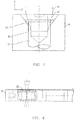
FIG. 3 is an exploded side view of one embodiment of the tool ofFIG. 1 and is constructed in accordance with the invention; -
FIG. 4 is a top view of one embodiment of the tool ofFIG. 3 and is constructed in accordance with the invention; -
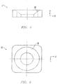
FIG. 5 is a sectional side view of one embodiment of a sliding washer for mounting the tool ofFIG. 3 and is constructed in accordance with the invention; -
FIG. 6 is a top view of one embodiment of the sliding washer ofFIG. 5 and is constructed in accordance with the invention; -
FIG. 7 is an enlarged schematic sectional side view of one embodiment of the tool ofFIG. 3 being used to remove a fastener from a workpiece and is constructed in accordance with the invention; and -
FIG. 8 is an enlarged sectional view of one embodiment of a drill bushing portion of the tool of F1G. 3 demonstrating a range of swivel motion of the drill bushing. - Referring to
FIGS. 1 - 8 , embodiments of a system, method, and apparatus for removing failed fasteners from structures are disclosed. The invention is particularly well suited for removing fasteners from structural components or assemblies that are formed from composite materials. - In one embodiment, the invention comprises a structure such as an assembly having two
structural components 11, 13 (FIGS. 1 and 2 ). The structure has a plurality ofholes 15 formed therein. Eachhole 15 has an axis extending in a transverse or "z" direction. Conventional existing or structure fasteners 17 (e.g., screws, bolts, etc.) are mounted in respective ones of theholes 15 for securing the assembly ofstructural components - A
guide 21 is positioned on the structure. Theguide 21 has abody 22 that generally extends in a longitudinal or "x" direction. Theguide 21 is mountable directly to the structure with at least one of the structure fasteners 17 (e.g., two are shown securingguide 21 to the structure). Theguide 21 has a width that extends in a lateral or "y" direction. - A
plate 25 is mounted to thebody 22 with fasteners and also extends in the x direction. Theplate 25 secures one or more sliding washers 27 (e.g., two shown inFIGS. 3 and 4 ) in aslot 29 formed between thebody 22 andplate 25. Detailed views of thesliding washers 27 are shown inFIGS. 5 and 6 . - As shown in
FIG. 4 , theplate 25 is provided with anoval aperture 31 extending in the x-direction and through which access to thesliding washers 27 is provided. Thestructure fasteners 17 extend through one or more of thesliding washers 27 to secure theguide 21 to the structure. - The sliding
washers 27 are slidably mounted and captured within theslot 29, which has a width extending in the y-direction in theguide 21. The slidingwashers 27 are movable in the x-direction relative to theguide 21. As shown in the drawings, at least two slidingwashers 27 may be provided in one embodiment, and each slidingwasher 27 is countersunk 28 (FIGS. 5 and 6 ) for thestructure fasteners 17. - Referring now to
FIGS. 2 - 4 , amaster bushing 23 is movably mounted to or in theguide 21. In one embodiment, themaster bushing 23 is swivel-mounted in theguide 21 and is retained in theguide 21 by snap rings. Themaster bushing 23 is located in an aperture having a spherical inner surface. Themaster bushing 23 has a spherical outer surface that is closely received by the aperture. As shown inFIG. 8 , this design gives the master bushing 23 a rotational range of freedom on the order of 15° to 17° relative to theguide 21. Slip fit renewable (SFR) bushings, sized appropriately for the selected cutting tool, are then utilized through themaster bushing 23 to provide accurate alignment of the cutting tool. - In one embodiment, the cutting tools may be provided with a stop 43 (
FIGS. 1 and 2 ) for limiting transverse travel of a cutting tool 41 (FIGS. 2 and7 ) relative to theguide 21. The cuttingtool 41 is located in and extends through themaster bushing 23 for cutting a selected one of thestructure fasteners 17 for removal from thestructure 11. The cuttingtool 41 may comprise a drill bit with a piloted countersink 45 (e.g.. formed on the order of 40 degrees to vertical) that is dependent on a diameter of thestructure fasteners 17. - The
guide 21 also has means for locking a motion of themaster bushing 23 relative to the guide. In one embodiment, the means for locking comprises a split sleeve 33 (FIGS. 3 and 4 ) that is formed about themaster bushing 23. A bolt or screw 35 extends laterally through thesplit sleeve 33 adjacent themaster bushing 23 for securing themaster bushing 23 in a desired orientation relative to theguide 21. - In one embodiment, the method accurately removes fouled fasteners from underlying structures. The guide is provided with interchangeable drill bushings to ensure proper cutting tool alignment and centrality throughout the process. For example, the invention may be provided with tools for removal of fasteners having a 3/8-inch (0.95cm) diameter, and kits for multiple other sizes, including 3/16-inch (0.48cm), 1/4-inch (0.64cm), 5/16-inch (0.79cm), 3/8-inch (0.95cm), etc. diameters.
- In operation, the method may comprise mounting the guide to the structure utilizing the existing fasteners already located in the structure. Using a drill with an appropriate driver 51 (e.g.,
FIGS. 1 and 2 ) a drill bit is extended through themaster bushing 23 and located at a center of (i.e., co-axially align with) thefastener 17 to be removed. After center alignment between the bit and the fastener to be removed, thebody 22 of theguide 21 is positioned such that at least one of the slidingwashers 27 aligns with another one of the existingstructure fasteners 17. The use of more than one slidingwasher 27 and existingstructure fastener 17 is desirable for additional stability during the process. These other structure fastener(s) 17 are then loosened and reinstalled into their holes after being inserted through the respective sliding washer(s) 27. The drill bit must still align the fastener to be removed after theguide 21 is attached and mounted to thestructure 11. - In one embodiment, a 1/4-inch (0.64cm) SFR drill bushing may be mounted in the
master bushing 23. A 1/4-inch (0.64cm) ball end carbide rotary file may be used to relieve or remove the drive slots formed in the head on the fastener to be removed. This allows for an uninterrupted drill start. A slow speed (e.g., 300 to 400 rpm) hand drill motor may be used for all fastener sizes. After relieving the fastener head drive slots, the SFR drill bushing may be changed to a #30 SFR drill bushing. - For example, for 3/8-inch (0.95cm) fasteners, the fastener to be removed may then be drilled to form a pilot hole therein with a #30 cobalt twist drill bit. After the #30 pilot hole is established, the SFR drill bushing may be changed to a 7/32-inch (0.56cm) SFR drill bushing, and the fastener then drilled with a 7/32" (0.56cm) cobalt (or other style) twist drill bit. At this stage, the technician may try using a #4 EZ-Out for removal of the fastener. In cases where the threads of the fastener are stripped, this procedure will remove the fastener. However, if the preceding step is unsuccessful, then the nut plate that secures the fastener is the problem (i.e., the nut plate spins). This will require the removal of the fastener head from its shank by cutting in order to complete the removal of the fouled fastener. The SFR drill bushing may be changed to a 5/16-inch (0.79cm) SFR drill bushing, and the fastener drilled with a 5/16-inch (0.79cm) cobalt twist drill bit. The 5/16" (0.79cm) SFR drill bushing is then removed from the
master bushing 23 and the head from the fastener is then removed utilizing the piloted countersink tool 41 (FIG. 7 ). Once thecountersink tool 41 completely cuts through the fastener head, the entire fastener (i.e., fastener shank and nut plate) will push through the structure and be effectively removed. Caution should be exercised during this operation to ensure that thecountersink tool 41 does not cut into the existingcountersink 61 in the structure. - The invention has numerous advantages over conventional failed fastener removal techniques. For example, the system allows for accurate, rigid location and support of cutting tools used in the removal of failed fasteners. This invention aids the technicians performing the removal, and also reduces the associated risks by cutting off the fastener head instead of relying on the head to break off.
- The invention provides a well-defined and repeatable removal process that allows suspect fasteners to be removed from composite materials without requiring expensive and time consuming rework of the composite material. The removal system mounts over the suspect fastener and provides a set of guides and bushings that allow a pilot hole to be made in the suspect fastener to an appropriate and repeatable diameter and depth. When necessary, a specialized cutting tool is applied using the same set of guides and bushings to remove the head without damaging the composite material. This method does not leave a burr or otherwise damage the composite material in which the fastener was installed.
- While the invention has been shown or described in only some of its forms, it should be apparent to those skilled in the art that it is not so limited, but is susceptible to various changes without departing from the scope of the invention as defined in the appended claims.
Claims (6)
- A system for removing failed fasteners, comprising:a structure (11, 12) having a plurality of holes (15) formed therein, each hole having an axis extending in a transverse z-direction;structure fasteners (17) mounted in respective ones of the holes (15);a guide (21) positioned on the structure (11,12), the guide (21) being mountable directly to the structure (11, 12) with at least one of the structure fasteners (17);a master bushing (23) that is swivel-mounted to the guide (21);a cutting tool (41) located in and extending through the master bushing (23) for cutting a fastener for removal from the structure (11, 12); and
a sliding washer (27) through which said at least one of the structure fasteners extends, and that is slidably mounted and captured within a slot (29) having a width in a lateral y-direction in the guide, the sliding washer being movable in a longitudinal direction that is perpendicular to the y-direction and the z-direction. - A system as claimed in Claim 1, wherein the master bushing (23) has a spherical outer surface and has a rotational range of freedom on the order of 15° to 17° relative to the guide (21).
- A system as claimed in Claim 1 or 2, wherein the cutting tool (41) has a stop for limiting a transverse travel of the cutting tool relative to the guide.
- A system according to any one of the preceding claims, wherein the cutting tool comprises a drill bit with a piloted countersink (45) that is dependent on a diameter of the structure fasteners (17).
- A system as claimed in any of Claims 1 to 4, wherein the sliding washer (27) comprises at least two sliding washers, and each sliding washer is countersunk (28) for the structure fasteners (17).
- A system as claimed in any of Claims 1 to 5, wherein the guide (21) comprises a body (22) extending in a longitudinal x-direction, a plate (25) mounted to the body for securing the sliding washer (27) in the slot (29), and means for locking a motion of the master bushing (23) relative to the guide; and wherein the means for locking comprises a split sleeve (33) formed about the master bushing (23) and a screw (35) extending laterally through the split sleeve adjacent the master bushing for securing the master bushing in a desired orientation relative to the guide (21).
Applications Claiming Priority (1)
| Application Number | Priority Date | Filing Date | Title |
|---|---|---|---|
| US12/113,228 US8292551B2 (en) | 2008-05-01 | 2008-05-01 | System, method and apparatus for removing failed fasteners |
Publications (4)
| Publication Number | Publication Date |
|---|---|
| EP2113324A2 EP2113324A2 (en) | 2009-11-04 |
| EP2113324A3 EP2113324A3 (en) | 2009-12-16 |
| EP2113324B1 EP2113324B1 (en) | 2018-04-04 |
| EP2113324B9 true EP2113324B9 (en) | 2018-05-23 |
Family
ID=40873435
Family Applications (1)
| Application Number | Title | Priority Date | Filing Date |
|---|---|---|---|
| EP09158978.8A Active EP2113324B9 (en) | 2008-05-01 | 2009-04-28 | System for removing failed fasteners |
Country Status (2)
| Country | Link |
|---|---|
| US (1) | US8292551B2 (en) |
| EP (1) | EP2113324B9 (en) |
Families Citing this family (10)
| Publication number | Priority date | Publication date | Assignee | Title |
|---|---|---|---|---|
| US8387226B2 (en) * | 2008-12-08 | 2013-03-05 | The Boeing Company | Method and apparatus for removing blind fasteners |
| JP5984684B2 (en) * | 2013-01-10 | 2016-09-06 | 三菱日立パワーシステムズ株式会社 | Drilling method, drilling jig, and heat exchanger |
| CN104942351B (en) * | 2015-05-25 | 2017-03-22 | 中国水利水电第十二工程局有限公司 | Large-size workpiece plane circular-arc groove machining device and method for milling circular-arc groove by using device |
| US10183393B2 (en) * | 2016-06-02 | 2019-01-22 | The Boeing Company | Level referencing drill guide |
| CN106270657A (en) * | 2016-08-30 | 2017-01-04 | 河南业豪幕墙装饰工程有限公司 | Curtain wall construction bore template and construction method |
| US10589363B2 (en) * | 2017-01-03 | 2020-03-17 | Beydler CNC | Universal tool for removing broken threaded fasteners |
| CN107552844B (en) * | 2017-09-04 | 2018-11-27 | 江西洪都航空工业集团有限责任公司 | A kind of plate nut gasket hole drilling die |
| CN112276151A (en) * | 2020-10-28 | 2021-01-29 | 中国航发贵州黎阳航空动力有限公司 | Hexagonal nut hexagonal lockwire hole drilling universal device |
| CN112589164B (en) * | 2020-11-11 | 2022-05-13 | 中国航发贵州黎阳航空动力有限公司 | Hole guiding device and method for processing cover plate riveting hole by using hole guiding device |
| CN114192844B (en) * | 2021-12-03 | 2023-09-22 | 中航沈飞民用飞机有限责任公司 | Aviation multi-lug high-precision full-jump machine processing tool and processing inspection method |
Family Cites Families (37)
| Publication number | Priority date | Publication date | Assignee | Title |
|---|---|---|---|---|
| US252704A (en) * | 1882-01-24 | Combined drill and countersink | ||
| US1954241A (en) * | 1927-07-16 | 1934-04-10 | Fannie E Hellyer | Milling tool |
| US1923847A (en) * | 1930-05-31 | 1933-08-22 | Frederick W Seelert | Valve seat cutting device |
| US2026821A (en) * | 1931-09-30 | 1936-01-07 | Charles H Cleveland | Apparatus for renewing worn valve seats |
| US2334845A (en) * | 1942-02-20 | 1943-11-23 | Francis Q Schwartz | Center drill |
| US2560382A (en) * | 1947-01-17 | 1951-07-10 | Francis A Barr | Drill jig |
| US2964115A (en) * | 1950-06-28 | 1960-12-13 | John J Clatfelter | Post hole boring devices |
| US2949798A (en) * | 1959-07-16 | 1960-08-23 | Jr Louis F Berta | Door pull template |
| DE1140047B (en) | 1959-09-17 | 1962-11-22 | Ernst Heinkel Flugzeugbau G M | Drill plate with a rotary disc eccentrically supporting the drill bush |
| US2963927A (en) * | 1959-10-26 | 1960-12-13 | Boeing Co | Self aligning drill motor clamp |
| CH445254A (en) * | 1967-03-01 | 1967-10-15 | Minelli Italo | Device for rotating valve seats on internal combustion engines |
| US3869803A (en) * | 1973-12-17 | 1975-03-11 | Peterson Machine Tool Inc | Drill guide for enlarging engine valve stem guides |
| US3977805A (en) * | 1974-07-26 | 1976-08-31 | Wanous Irvin E | Tool bar holder |
| US4041834A (en) | 1976-08-24 | 1977-08-16 | Illinois Tool Works Inc. | Plastic headed fastener assembly |
| US4802805A (en) | 1980-01-14 | 1989-02-07 | William P. Green | Fatigue resistant fasteners and related methods |
| US4545104A (en) | 1980-01-14 | 1985-10-08 | William P. Green | Method of forming a fatigue resistant threaded connection |
| US4684299A (en) * | 1985-07-15 | 1987-08-04 | Laliberte Roger J | Liberty jig |
| US4850756A (en) * | 1987-12-17 | 1989-07-25 | Dubois Gerald J | Portable align boring machine |
| US4948318A (en) | 1989-04-03 | 1990-08-14 | Textron, Inc. | Non-corrosive headed composite fasteners and a method of producing the same |
| US5018912A (en) * | 1990-05-18 | 1991-05-28 | By George Enterprises, Inc. | Drilling jig for stair rails |
| US5547325A (en) | 1994-02-18 | 1996-08-20 | Utility Composites, Inc. | Nail packs made of composites having high compressive strength and flexural modules |
| US5743684A (en) * | 1996-10-25 | 1998-04-28 | Rex Systems, Inc. | Adjustable drill hole jig for carpentry applications |
| US6042315A (en) | 1997-10-06 | 2000-03-28 | United Technologies Corporation | Fastener |
| US6045310A (en) | 1997-10-06 | 2000-04-04 | United Technologies Corporation | Composite fastener for use in high temperature environments |
| CA2375105C (en) | 1999-05-31 | 2008-09-09 | David Llewellen Owen | Screens |
| US20030056622A1 (en) | 1999-11-12 | 2003-03-27 | Jordan Chalmer C. | Tool for removing damaged fasteners and securing new fasteners and improved method for making such tool |
| US6773215B2 (en) | 2002-09-11 | 2004-08-10 | United Technologies Corporation | Fastener assembly for use with composite articles |
| US7225510B2 (en) | 2003-03-05 | 2007-06-05 | Velern Industries B.V. | Fastener product |
| US6910252B2 (en) | 2003-03-27 | 2005-06-28 | The Boeing Company | Apparatus for removing a fastener from a workpiece |
| US6978697B2 (en) * | 2003-04-25 | 2005-12-27 | Eazypower, Corporation | Damaged bolt and screw removing devices |
| US20040261232A1 (en) | 2003-06-26 | 2004-12-30 | Kurtz Wallace L. | Fastener product with multiple engagement angles |
| US7059216B2 (en) | 2003-09-03 | 2006-06-13 | Huck International Inc. | Fastener removal apparatus |
| US8079995B2 (en) | 2003-11-06 | 2011-12-20 | Velcro Industries B.V. | Composite fastener products |
| US20050150331A1 (en) | 2004-01-14 | 2005-07-14 | Horobec Bill R. | Removal of damaged fasteners |
| US7150594B2 (en) | 2004-03-09 | 2006-12-19 | The Boeing Company | Hybrid fastener apparatus and method for fastening |
| US20050204542A1 (en) | 2004-03-17 | 2005-09-22 | Bernard Pittman | Cylinder head stud removal tool |
| US20050216027A1 (en) | 2004-03-24 | 2005-09-29 | Suh Sean S | Extraction screwdriver |
-
2008
- 2008-05-01 US US12/113,228 patent/US8292551B2/en active Active
-
2009
- 2009-04-28 EP EP09158978.8A patent/EP2113324B9/en active Active
Also Published As
| Publication number | Publication date |
|---|---|
| EP2113324B1 (en) | 2018-04-04 |
| US8292551B2 (en) | 2012-10-23 |
| US20090274526A1 (en) | 2009-11-05 |
| EP2113324A2 (en) | 2009-11-04 |
| EP2113324A3 (en) | 2009-12-16 |
Similar Documents
| Publication | Publication Date | Title |
|---|---|---|
| EP2113324B1 (en) | System for removing failed fasteners | |
| KR20110042354A (en) | Universal tool mounting system for machining center | |
| CN1935430A (en) | Drilling/grinding integrated combined tool | |
| CA2473318A1 (en) | Cylinder head stud removal tool | |
| CN201735837U (en) | Tool fixture assembly capable of adjusting depth of step drill | |
| CN106042093A (en) | Positioning hole punching device | |
| CN107081453A (en) | A kind of drilling jig tool for boring Flywheel disc angle hole | |
| US20070079489A1 (en) | Rotational tool alignment adapter arrangement and associated provision method | |
| US20020119018A1 (en) | Template guide for centering drill in removing of broken stud | |
| US20200030894A1 (en) | Drilling Tool Comprising A Replaceable Cutting Disk | |
| EP3130421B1 (en) | Apparatus for hole repair comprising a bottom cutting step up reamer | |
| CN211889040U (en) | Adjustable coaxial hole machining tool | |
| CN210254305U (en) | Boring cutter | |
| CN220739499U (en) | Inner and outer diameter integrated adjustable boring cutter | |
| CN213969142U (en) | A quick tool changer for automatic feed drill | |
| CN215824792U (en) | Special machine tool for machining threaded holes in end faces of machine cylinders | |
| CN100531982C (en) | Taper Mounted Eccentric Machine Chuck Deep Hole Drill Bits and Inserts | |
| CN209902314U (en) | Drilling device | |
| CN222725484U (en) | Multi-station hole machining tool fixing tool based on lathe | |
| DE102023119396B3 (en) | Procedure for replacing a defective screw connection and countersink | |
| CN216991001U (en) | CNC machining center quick tool changing mechanism | |
| WO2001015846A1 (en) | Quick-change tool holders | |
| US7444757B2 (en) | System and method for aligning a machine-tool with a spindle | |
| CN223056792U (en) | A tungsten steel end mill with anti-flying structure | |
| EP3043938B1 (en) | Cutting tool |
Legal Events
| Date | Code | Title | Description |
|---|---|---|---|
| PUAI | Public reference made under article 153(3) epc to a published international application that has entered the european phase |
Free format text: ORIGINAL CODE: 0009012 |
|
| 17P | Request for examination filed |
Effective date: 20090428 |
|
| AK | Designated contracting states |
Kind code of ref document: A2 Designated state(s): AT BE BG CH CY CZ DE DK EE ES FI FR GB GR HR HU IE IS IT LI LT LU LV MC MK MT NL NO PL PT RO SE SI SK TR |
|
| PUAL | Search report despatched |
Free format text: ORIGINAL CODE: 0009013 |
|
| AK | Designated contracting states |
Kind code of ref document: A3 Designated state(s): AT BE BG CH CY CZ DE DK EE ES FI FR GB GR HR HU IE IS IT LI LT LU LV MC MK MT NL NO PL PT RO SE SI SK TR |
|
| 17Q | First examination report despatched |
Effective date: 20100616 |
|
| GRAP | Despatch of communication of intention to grant a patent |
Free format text: ORIGINAL CODE: EPIDOSNIGR1 |
|
| INTG | Intention to grant announced |
Effective date: 20171024 |
|
| GRAS | Grant fee paid |
Free format text: ORIGINAL CODE: EPIDOSNIGR3 |
|
| GRAA | (expected) grant |
Free format text: ORIGINAL CODE: 0009210 |
|
| GRAT | Correction requested after decision to grant or after decision to maintain patent in amended form |
Free format text: ORIGINAL CODE: EPIDOSNCDEC |
|
| AK | Designated contracting states |
Kind code of ref document: B1 Designated state(s): AT BE BG CH CY CZ DE DK EE ES FI FR GB GR HR HU IE IS IT LI LT LU LV MC MK MT NL NO PL PT RO SE SI SK TR |
|
| REG | Reference to a national code |
Ref country code: GB Ref legal event code: FG4D |
|
| REG | Reference to a national code |
Ref country code: CH Ref legal event code: EP |
|
| REG | Reference to a national code |
Ref country code: AT Ref legal event code: REF Ref document number: 985059 Country of ref document: AT Kind code of ref document: T Effective date: 20180415 |
|
| REG | Reference to a national code |
Ref country code: IE Ref legal event code: FG4D |
|
| REG | Reference to a national code |
Ref country code: DE Ref legal event code: R096 Ref document number: 602009051577 Country of ref document: DE |
|
| REG | Reference to a national code |
Ref country code: FR Ref legal event code: PLFP Year of fee payment: 10 |
|
| REG | Reference to a national code |
Ref country code: NL Ref legal event code: MP Effective date: 20180404 |
|
| REG | Reference to a national code |
Ref country code: LT Ref legal event code: MG4D |
|
| PG25 | Lapsed in a contracting state [announced via postgrant information from national office to epo] |
Ref country code: NL Free format text: LAPSE BECAUSE OF FAILURE TO SUBMIT A TRANSLATION OF THE DESCRIPTION OR TO PAY THE FEE WITHIN THE PRESCRIBED TIME-LIMIT Effective date: 20180404 |
|
| PG25 | Lapsed in a contracting state [announced via postgrant information from national office to epo] |
Ref country code: BG Free format text: LAPSE BECAUSE OF FAILURE TO SUBMIT A TRANSLATION OF THE DESCRIPTION OR TO PAY THE FEE WITHIN THE PRESCRIBED TIME-LIMIT Effective date: 20180704 Ref country code: NO Free format text: LAPSE BECAUSE OF FAILURE TO SUBMIT A TRANSLATION OF THE DESCRIPTION OR TO PAY THE FEE WITHIN THE PRESCRIBED TIME-LIMIT Effective date: 20180704 Ref country code: FI Free format text: LAPSE BECAUSE OF FAILURE TO SUBMIT A TRANSLATION OF THE DESCRIPTION OR TO PAY THE FEE WITHIN THE PRESCRIBED TIME-LIMIT Effective date: 20180404 Ref country code: SE Free format text: LAPSE BECAUSE OF FAILURE TO SUBMIT A TRANSLATION OF THE DESCRIPTION OR TO PAY THE FEE WITHIN THE PRESCRIBED TIME-LIMIT Effective date: 20180404 Ref country code: PL Free format text: LAPSE BECAUSE OF FAILURE TO SUBMIT A TRANSLATION OF THE DESCRIPTION OR TO PAY THE FEE WITHIN THE PRESCRIBED TIME-LIMIT Effective date: 20180404 Ref country code: LT Free format text: LAPSE BECAUSE OF FAILURE TO SUBMIT A TRANSLATION OF THE DESCRIPTION OR TO PAY THE FEE WITHIN THE PRESCRIBED TIME-LIMIT Effective date: 20180404 Ref country code: ES Free format text: LAPSE BECAUSE OF FAILURE TO SUBMIT A TRANSLATION OF THE DESCRIPTION OR TO PAY THE FEE WITHIN THE PRESCRIBED TIME-LIMIT Effective date: 20180404 |
|
| PG25 | Lapsed in a contracting state [announced via postgrant information from national office to epo] |
Ref country code: LV Free format text: LAPSE BECAUSE OF FAILURE TO SUBMIT A TRANSLATION OF THE DESCRIPTION OR TO PAY THE FEE WITHIN THE PRESCRIBED TIME-LIMIT Effective date: 20180404 Ref country code: HR Free format text: LAPSE BECAUSE OF FAILURE TO SUBMIT A TRANSLATION OF THE DESCRIPTION OR TO PAY THE FEE WITHIN THE PRESCRIBED TIME-LIMIT Effective date: 20180404 Ref country code: GR Free format text: LAPSE BECAUSE OF FAILURE TO SUBMIT A TRANSLATION OF THE DESCRIPTION OR TO PAY THE FEE WITHIN THE PRESCRIBED TIME-LIMIT Effective date: 20180705 |
|
| REG | Reference to a national code |
Ref country code: CH Ref legal event code: PL |
|
| REG | Reference to a national code |
Ref country code: AT Ref legal event code: MK05 Ref document number: 985059 Country of ref document: AT Kind code of ref document: T Effective date: 20180404 |
|
| REG | Reference to a national code |
Ref country code: BE Ref legal event code: MM Effective date: 20180430 |
|
| PG25 | Lapsed in a contracting state [announced via postgrant information from national office to epo] |
Ref country code: PT Free format text: LAPSE BECAUSE OF FAILURE TO SUBMIT A TRANSLATION OF THE DESCRIPTION OR TO PAY THE FEE WITHIN THE PRESCRIBED TIME-LIMIT Effective date: 20180806 |
|
| REG | Reference to a national code |
Ref country code: DE Ref legal event code: R097 Ref document number: 602009051577 Country of ref document: DE |
|
| REG | Reference to a national code |
Ref country code: IE Ref legal event code: MM4A |
|
| PG25 | Lapsed in a contracting state [announced via postgrant information from national office to epo] |
Ref country code: AT Free format text: LAPSE BECAUSE OF FAILURE TO SUBMIT A TRANSLATION OF THE DESCRIPTION OR TO PAY THE FEE WITHIN THE PRESCRIBED TIME-LIMIT Effective date: 20180404 Ref country code: DK Free format text: LAPSE BECAUSE OF FAILURE TO SUBMIT A TRANSLATION OF THE DESCRIPTION OR TO PAY THE FEE WITHIN THE PRESCRIBED TIME-LIMIT Effective date: 20180404 Ref country code: RO Free format text: LAPSE BECAUSE OF FAILURE TO SUBMIT A TRANSLATION OF THE DESCRIPTION OR TO PAY THE FEE WITHIN THE PRESCRIBED TIME-LIMIT Effective date: 20180404 Ref country code: EE Free format text: LAPSE BECAUSE OF FAILURE TO SUBMIT A TRANSLATION OF THE DESCRIPTION OR TO PAY THE FEE WITHIN THE PRESCRIBED TIME-LIMIT Effective date: 20180404 Ref country code: CZ Free format text: LAPSE BECAUSE OF FAILURE TO SUBMIT A TRANSLATION OF THE DESCRIPTION OR TO PAY THE FEE WITHIN THE PRESCRIBED TIME-LIMIT Effective date: 20180404 Ref country code: SK Free format text: LAPSE BECAUSE OF FAILURE TO SUBMIT A TRANSLATION OF THE DESCRIPTION OR TO PAY THE FEE WITHIN THE PRESCRIBED TIME-LIMIT Effective date: 20180404 Ref country code: LU Free format text: LAPSE BECAUSE OF NON-PAYMENT OF DUE FEES Effective date: 20180428 Ref country code: MC Free format text: LAPSE BECAUSE OF FAILURE TO SUBMIT A TRANSLATION OF THE DESCRIPTION OR TO PAY THE FEE WITHIN THE PRESCRIBED TIME-LIMIT Effective date: 20180404 |
|
| PLBE | No opposition filed within time limit |
Free format text: ORIGINAL CODE: 0009261 |
|
| STAA | Information on the status of an ep patent application or granted ep patent |
Free format text: STATUS: NO OPPOSITION FILED WITHIN TIME LIMIT |
|
| PG25 | Lapsed in a contracting state [announced via postgrant information from national office to epo] |
Ref country code: LI Free format text: LAPSE BECAUSE OF NON-PAYMENT OF DUE FEES Effective date: 20180430 Ref country code: BE Free format text: LAPSE BECAUSE OF NON-PAYMENT OF DUE FEES Effective date: 20180430 Ref country code: CH Free format text: LAPSE BECAUSE OF NON-PAYMENT OF DUE FEES Effective date: 20180430 |
|
| 26N | No opposition filed |
Effective date: 20190107 |
|
| PG25 | Lapsed in a contracting state [announced via postgrant information from national office to epo] |
Ref country code: IE Free format text: LAPSE BECAUSE OF NON-PAYMENT OF DUE FEES Effective date: 20180428 |
|
| PG25 | Lapsed in a contracting state [announced via postgrant information from national office to epo] |
Ref country code: SI Free format text: LAPSE BECAUSE OF FAILURE TO SUBMIT A TRANSLATION OF THE DESCRIPTION OR TO PAY THE FEE WITHIN THE PRESCRIBED TIME-LIMIT Effective date: 20180404 |
|
| PG25 | Lapsed in a contracting state [announced via postgrant information from national office to epo] |
Ref country code: MT Free format text: LAPSE BECAUSE OF NON-PAYMENT OF DUE FEES Effective date: 20180428 |
|
| PG25 | Lapsed in a contracting state [announced via postgrant information from national office to epo] |
Ref country code: TR Free format text: LAPSE BECAUSE OF FAILURE TO SUBMIT A TRANSLATION OF THE DESCRIPTION OR TO PAY THE FEE WITHIN THE PRESCRIBED TIME-LIMIT Effective date: 20180404 |
|
| PG25 | Lapsed in a contracting state [announced via postgrant information from national office to epo] |
Ref country code: HU Free format text: LAPSE BECAUSE OF FAILURE TO SUBMIT A TRANSLATION OF THE DESCRIPTION OR TO PAY THE FEE WITHIN THE PRESCRIBED TIME-LIMIT; INVALID AB INITIO Effective date: 20090428 |
|
| PG25 | Lapsed in a contracting state [announced via postgrant information from national office to epo] |
Ref country code: CY Free format text: LAPSE BECAUSE OF FAILURE TO SUBMIT A TRANSLATION OF THE DESCRIPTION OR TO PAY THE FEE WITHIN THE PRESCRIBED TIME-LIMIT Effective date: 20180404 Ref country code: MK Free format text: LAPSE BECAUSE OF NON-PAYMENT OF DUE FEES Effective date: 20180404 |
|
| PG25 | Lapsed in a contracting state [announced via postgrant information from national office to epo] |
Ref country code: IS Free format text: LAPSE BECAUSE OF FAILURE TO SUBMIT A TRANSLATION OF THE DESCRIPTION OR TO PAY THE FEE WITHIN THE PRESCRIBED TIME-LIMIT Effective date: 20180804 |
|
| PGFP | Annual fee paid to national office [announced via postgrant information from national office to epo] |
Ref country code: DE Payment date: 20250429 Year of fee payment: 17 |
|
| PGFP | Annual fee paid to national office [announced via postgrant information from national office to epo] |
Ref country code: IT Payment date: 20250422 Year of fee payment: 17 |
|
| PGFP | Annual fee paid to national office [announced via postgrant information from national office to epo] |
Ref country code: FR Payment date: 20250425 Year of fee payment: 17 |
|
| PGFP | Annual fee paid to national office [announced via postgrant information from national office to epo] |
Ref country code: GB Payment date: 20260327 Year of fee payment: 18 |