EP2113299A1 - Improved operation of catalyst withdrawal wells with packing - Google Patents
Improved operation of catalyst withdrawal wells with packing Download PDFInfo
- Publication number
- EP2113299A1 EP2113299A1 EP09005668A EP09005668A EP2113299A1 EP 2113299 A1 EP2113299 A1 EP 2113299A1 EP 09005668 A EP09005668 A EP 09005668A EP 09005668 A EP09005668 A EP 09005668A EP 2113299 A1 EP2113299 A1 EP 2113299A1
- Authority
- EP
- European Patent Office
- Prior art keywords
- catalyst
- well
- standpipe
- withdrawal well
- packing
- Prior art date
- Legal status (The legal status is an assumption and is not a legal conclusion. Google has not performed a legal analysis and makes no representation as to the accuracy of the status listed.)
- Withdrawn
Links
- 239000003054 catalyst Substances 0.000 title claims abstract description 110
- 238000012856 packing Methods 0.000 title claims abstract description 20
- 238000005243 fluidization Methods 0.000 claims description 17
- 239000000203 mixture Substances 0.000 claims 1
- 239000007787 solid Substances 0.000 abstract description 2
- 239000007789 gas Substances 0.000 description 12
- 229930195733 hydrocarbon Natural products 0.000 description 9
- 150000002430 hydrocarbons Chemical class 0.000 description 9
- 239000004215 Carbon black (E152) Substances 0.000 description 6
- 238000004523 catalytic cracking Methods 0.000 description 6
- UGFAIRIUMAVXCW-UHFFFAOYSA-N Carbon monoxide Chemical compound [O+]#[C-] UGFAIRIUMAVXCW-UHFFFAOYSA-N 0.000 description 4
- 239000000571 coke Substances 0.000 description 4
- 239000003546 flue gas Substances 0.000 description 4
- 238000000034 method Methods 0.000 description 4
- 230000008569 process Effects 0.000 description 4
- 238000000926 separation method Methods 0.000 description 4
- QVGXLLKOCUKJST-UHFFFAOYSA-N atomic oxygen Chemical compound [O] QVGXLLKOCUKJST-UHFFFAOYSA-N 0.000 description 3
- 238000005336 cracking Methods 0.000 description 3
- 239000010410 layer Substances 0.000 description 3
- 239000001301 oxygen Substances 0.000 description 3
- 229910052760 oxygen Inorganic materials 0.000 description 3
- IJGRMHOSHXDMSA-UHFFFAOYSA-N Atomic nitrogen Chemical compound N#N IJGRMHOSHXDMSA-UHFFFAOYSA-N 0.000 description 2
- 230000007812 deficiency Effects 0.000 description 2
- 238000013461 design Methods 0.000 description 2
- 238000011143 downstream manufacturing Methods 0.000 description 2
- 238000004231 fluid catalytic cracking Methods 0.000 description 2
- 239000003502 gasoline Substances 0.000 description 2
- JTJMJGYZQZDUJJ-UHFFFAOYSA-N phencyclidine Chemical class C1CCCCN1C1(C=2C=CC=CC=2)CCCCC1 JTJMJGYZQZDUJJ-UHFFFAOYSA-N 0.000 description 2
- 238000005273 aeration Methods 0.000 description 1
- 150000001336 alkenes Chemical class 0.000 description 1
- 230000005587 bubbling Effects 0.000 description 1
- 230000003197 catalytic effect Effects 0.000 description 1
- 238000006555 catalytic reaction Methods 0.000 description 1
- 238000004581 coalescence Methods 0.000 description 1
- 238000002485 combustion reaction Methods 0.000 description 1
- 239000003085 diluting agent Substances 0.000 description 1
- 238000009826 distribution Methods 0.000 description 1
- 239000002737 fuel gas Substances 0.000 description 1
- -1 gasoline and olefins Chemical class 0.000 description 1
- 239000012535 impurity Substances 0.000 description 1
- 239000011261 inert gas Substances 0.000 description 1
- 238000004519 manufacturing process Methods 0.000 description 1
- 238000012986 modification Methods 0.000 description 1
- 230000004048 modification Effects 0.000 description 1
- 229910052757 nitrogen Inorganic materials 0.000 description 1
- 239000002245 particle Substances 0.000 description 1
- 238000011084 recovery Methods 0.000 description 1
- 230000009467 reduction Effects 0.000 description 1
- 230000008929 regeneration Effects 0.000 description 1
- 238000011069 regeneration method Methods 0.000 description 1
- 239000002356 single layer Substances 0.000 description 1
- 238000012546 transfer Methods 0.000 description 1
- 230000007704 transition Effects 0.000 description 1
- 238000009827 uniform distribution Methods 0.000 description 1
- XLYOFNOQVPJJNP-UHFFFAOYSA-N water Substances O XLYOFNOQVPJJNP-UHFFFAOYSA-N 0.000 description 1
Images

Classifications
-
- B—PERFORMING OPERATIONS; TRANSPORTING
- B01—PHYSICAL OR CHEMICAL PROCESSES OR APPARATUS IN GENERAL
- B01J—CHEMICAL OR PHYSICAL PROCESSES, e.g. CATALYSIS OR COLLOID CHEMISTRY; THEIR RELEVANT APPARATUS
- B01J8/00—Chemical or physical processes in general, conducted in the presence of fluids and solid particles; Apparatus for such processes
- B01J8/18—Chemical or physical processes in general, conducted in the presence of fluids and solid particles; Apparatus for such processes with fluidised particles
- B01J8/24—Chemical or physical processes in general, conducted in the presence of fluids and solid particles; Apparatus for such processes with fluidised particles according to "fluidised-bed" technique
- B01J8/38—Chemical or physical processes in general, conducted in the presence of fluids and solid particles; Apparatus for such processes with fluidised particles according to "fluidised-bed" technique with fluidised bed containing a rotatable device or being subject to rotation or to a circulatory movement, i.e. leaving a vessel and subsequently re-entering it
- B01J8/384—Chemical or physical processes in general, conducted in the presence of fluids and solid particles; Apparatus for such processes with fluidised particles according to "fluidised-bed" technique with fluidised bed containing a rotatable device or being subject to rotation or to a circulatory movement, i.e. leaving a vessel and subsequently re-entering it being subject to a circulatory movement only
- B01J8/388—Chemical or physical processes in general, conducted in the presence of fluids and solid particles; Apparatus for such processes with fluidised particles according to "fluidised-bed" technique with fluidised bed containing a rotatable device or being subject to rotation or to a circulatory movement, i.e. leaving a vessel and subsequently re-entering it being subject to a circulatory movement only externally, i.e. the particles leaving the vessel and subsequently re-entering it
-
- B—PERFORMING OPERATIONS; TRANSPORTING
- B01—PHYSICAL OR CHEMICAL PROCESSES OR APPARATUS IN GENERAL
- B01J—CHEMICAL OR PHYSICAL PROCESSES, e.g. CATALYSIS OR COLLOID CHEMISTRY; THEIR RELEVANT APPARATUS
- B01J38/00—Regeneration or reactivation of catalysts, in general
- B01J38/04—Gas or vapour treating; Treating by using liquids vaporisable upon contacting spent catalyst
- B01J38/12—Treating with free oxygen-containing gas
- B01J38/30—Treating with free oxygen-containing gas in gaseous suspension, e.g. fluidised bed
-
- B—PERFORMING OPERATIONS; TRANSPORTING
- B01—PHYSICAL OR CHEMICAL PROCESSES OR APPARATUS IN GENERAL
- B01J—CHEMICAL OR PHYSICAL PROCESSES, e.g. CATALYSIS OR COLLOID CHEMISTRY; THEIR RELEVANT APPARATUS
- B01J8/00—Chemical or physical processes in general, conducted in the presence of fluids and solid particles; Apparatus for such processes
- B01J8/005—Separating solid material from the gas/liquid stream
- B01J8/0055—Separating solid material from the gas/liquid stream using cyclones
-
- B—PERFORMING OPERATIONS; TRANSPORTING
- B01—PHYSICAL OR CHEMICAL PROCESSES OR APPARATUS IN GENERAL
- B01J—CHEMICAL OR PHYSICAL PROCESSES, e.g. CATALYSIS OR COLLOID CHEMISTRY; THEIR RELEVANT APPARATUS
- B01J8/00—Chemical or physical processes in general, conducted in the presence of fluids and solid particles; Apparatus for such processes
- B01J8/18—Chemical or physical processes in general, conducted in the presence of fluids and solid particles; Apparatus for such processes with fluidised particles
- B01J8/1845—Chemical or physical processes in general, conducted in the presence of fluids and solid particles; Apparatus for such processes with fluidised particles with particles moving upwards while fluidised
- B01J8/1863—Chemical or physical processes in general, conducted in the presence of fluids and solid particles; Apparatus for such processes with fluidised particles with particles moving upwards while fluidised followed by a downward movement outside the reactor and subsequently re-entering it
-
- B—PERFORMING OPERATIONS; TRANSPORTING
- B01—PHYSICAL OR CHEMICAL PROCESSES OR APPARATUS IN GENERAL
- B01J—CHEMICAL OR PHYSICAL PROCESSES, e.g. CATALYSIS OR COLLOID CHEMISTRY; THEIR RELEVANT APPARATUS
- B01J8/00—Chemical or physical processes in general, conducted in the presence of fluids and solid particles; Apparatus for such processes
- B01J8/18—Chemical or physical processes in general, conducted in the presence of fluids and solid particles; Apparatus for such processes with fluidised particles
- B01J8/24—Chemical or physical processes in general, conducted in the presence of fluids and solid particles; Apparatus for such processes with fluidised particles according to "fluidised-bed" technique
- B01J8/26—Chemical or physical processes in general, conducted in the presence of fluids and solid particles; Apparatus for such processes with fluidised particles according to "fluidised-bed" technique with two or more fluidised beds, e.g. reactor and regeneration installations
-
- B—PERFORMING OPERATIONS; TRANSPORTING
- B01—PHYSICAL OR CHEMICAL PROCESSES OR APPARATUS IN GENERAL
- B01J—CHEMICAL OR PHYSICAL PROCESSES, e.g. CATALYSIS OR COLLOID CHEMISTRY; THEIR RELEVANT APPARATUS
- B01J8/00—Chemical or physical processes in general, conducted in the presence of fluids and solid particles; Apparatus for such processes
- B01J8/18—Chemical or physical processes in general, conducted in the presence of fluids and solid particles; Apparatus for such processes with fluidised particles
- B01J8/24—Chemical or physical processes in general, conducted in the presence of fluids and solid particles; Apparatus for such processes with fluidised particles according to "fluidised-bed" technique
- B01J8/34—Chemical or physical processes in general, conducted in the presence of fluids and solid particles; Apparatus for such processes with fluidised particles according to "fluidised-bed" technique with stationary packing material in the fluidised bed, e.g. bricks, wire rings, baffles
-
- C—CHEMISTRY; METALLURGY
- C10—PETROLEUM, GAS OR COKE INDUSTRIES; TECHNICAL GASES CONTAINING CARBON MONOXIDE; FUELS; LUBRICANTS; PEAT
- C10G—CRACKING HYDROCARBON OILS; PRODUCTION OF LIQUID HYDROCARBON MIXTURES, e.g. BY DESTRUCTIVE HYDROGENATION, OLIGOMERISATION, POLYMERISATION; RECOVERY OF HYDROCARBON OILS FROM OIL-SHALE, OIL-SAND, OR GASES; REFINING MIXTURES MAINLY CONSISTING OF HYDROCARBONS; REFORMING OF NAPHTHA; MINERAL WAXES
- C10G11/00—Catalytic cracking, in the absence of hydrogen, of hydrocarbon oils
- C10G11/14—Catalytic cracking, in the absence of hydrogen, of hydrocarbon oils with preheated moving solid catalysts
- C10G11/18—Catalytic cracking, in the absence of hydrogen, of hydrocarbon oils with preheated moving solid catalysts according to the "fluidised-bed" technique
- C10G11/182—Regeneration
-
- C—CHEMISTRY; METALLURGY
- C10—PETROLEUM, GAS OR COKE INDUSTRIES; TECHNICAL GASES CONTAINING CARBON MONOXIDE; FUELS; LUBRICANTS; PEAT
- C10G—CRACKING HYDROCARBON OILS; PRODUCTION OF LIQUID HYDROCARBON MIXTURES, e.g. BY DESTRUCTIVE HYDROGENATION, OLIGOMERISATION, POLYMERISATION; RECOVERY OF HYDROCARBON OILS FROM OIL-SHALE, OIL-SAND, OR GASES; REFINING MIXTURES MAINLY CONSISTING OF HYDROCARBONS; REFORMING OF NAPHTHA; MINERAL WAXES
- C10G2300/00—Aspects relating to hydrocarbon processing covered by groups C10G1/00 - C10G99/00
- C10G2300/40—Characteristics of the process deviating from typical ways of processing
- C10G2300/4093—Catalyst stripping
Definitions
- the present invention relates to an improved catalyst withdrawal well containing packing or other structured internals for improving the flow of particular solids between two apparatus, such as between a catalyst regenerator and a riser reactor and the improved operation of a catalyst withdrawal well. More particularly, the present invention relates to a catalyst withdrawal well for use in transporting regenerated catalyst from a catalyst regenerator to a riser reactor in an FCC system. Most particularly, the present invention relates to a fluidized catalyst withdrawal well that contains packing or baffles.
- Catalytic cracking processes for catalytically cracking hydrocarbon feedstocks to more valuable hydrocarbons, such as gasoline and olefins have been known for decades.
- hot regenerated catalyst and feedstock and optionally steam or other diluent gas
- the spent catalyst typically is contaminated with coke and other hydrocarbon impurities from the cracking process.
- the cracked products and spent catalyst are separated in a separating system and the cracked product is withdrawn for downstream processing.
- the separated spent catalyst are discharged to a dense catalyst bed in a disengager vessel, wherein they are contacted with a stripping medium, typically steam, to remove volatile hydrocarbon products from the catalyst.
- a stripping medium typically steam
- the spent catalyst containing coke then passes through a stripper standpipe to enter a catalyst regenerator where, in the presence of air and at combustion conditions, the coke is burned off of the catalyst to produce hot regenerated catalyst and flue gas.
- the flue gas is separated from the regenerated catalyst, such as by cyclones, and withdrawn from the regenerator vessel.
- the hot regenerated catalyst is collected in a dense fluidized bed in the regenerator and then withdrawn through a standpipe for recycle to the riser reactor.
- the catalyst provides both the catalytic activity and the heat for the catalytic reaction, proper catalyst circulation through the system is important to the overall performance of the FCC unit.
- the main drive for catalyst circulation comes from stable and adequate pressure build-up in the withdrawal standpipe.
- the prior art has attempted to address standpipe design.
- a number of catalytic cracking patents do not describe any particular standpipe configuration in catalyst regeneration for hydrocarbon treatment processes, describing simply a standpipe. See, for example, United States Patent Nos. 5,143,875 ; 4,431,856 ; 4,238,631 ; 2,700,639 ; 2,784,826 ; 2,860,102 ; 2,761,820 and 2,913,402 .
- Conical standpipe inlet hoppers for reducing gas entrainment in the standpipe, for both stripper standpipe and regenerator standpipes, are known in the art.
- the present inventors have found that the presence of internal structures in the withdrawal well, such as single or multiple layers of packing or baffles, located above and/or below the fluidization rings overcomes the deficiencies of the prior art.
- the packing and/or baffles break up de-fluidized catalyst that enter the withdrawal well as "clumps" or catalyst by redistributing the catalyst and mixing it up in the bed.
- the structured packing or baffles also promotes more even distribution of the fluidization gas as it travels counter-current to the catalysts inside the withdrawal well internals.
- the catalyst exiting the packed zone is well aerated and uniform in density. The internals therefore re-distribute the catalyst and more evenly re-aerate the catalyst prior to entry into the standpipe.
- the pressure build up in the standpipe improves because the standpipe will operate in fluidized regime instead of packed bed regime.
- the improved density uniformity provided by the present invention enables the density of the catalyst entering the standpipe to be higher than in the prior art designs and, in fact, can be adjusted by adjusting the aeration rate to give a higher density, which provides benefits.
- the higher standpipe density provides more standpipe head pressure and therefore a higher delta P across the regenerated catalyst slide valve.
- the higher density means less entrained gases going to the reactor.
- the entrained gases from the regenerator are largely non-condensables (N 2 and CO 2 ) that add to the wet gas compressor load.
- excess oxygen is being used in the regenerator, then less oxygen will be entrained into the reactor as well, resulting in the production of less undesirable products in the gasoline and sour water.
- the present invention will be described in the context of a withdrawal well between a catalyst regenerator and a riser reactor, although the concept is applicable to wells between other vessels, such as between a stripper and the catalyst regenerator.
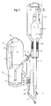
- fluidized catalytic cracking system 2 comprised of a riser reactor 4, disengager vessel 6 and regenerator 8.
- hot regenerated catalyst from standpipe 10 enters the riser reactor 4 wherein it is contacted with hydrocarbon feedstock supplied through nozzle 12.
- fluidized catalyst cracking system 2 is general in nature showing the riser 4 internal to the disengager 6, but it could be external as well.
- any feedstock nozzle configuration may be employed. It is not the configuration of the fluid catalytic cracking system that is critical to the present invention. Rather it is the employment of the improved catalyst withdrawal well 14 described more fully herein below.
- the hydrocarbon feedstock is contacted with the hot regenerated catalyst at catalytic cracking conditions known to those skilled in the art to produce spent catalyst and cracked products.
- the top of the riser is connected via an internal transfer conduit to a separation system 16.
- any separation system known to those skilled in the art such as but not limited to rough cut, closed system, open system, close coupled system etc, may be employed in the practice of the present invention.
- the separation system 16 separates spent catalyst from the cracked gases with the cracked gases entering the reactor cyclones 28 via a connecting conduit 22, 19 and 30.
- the separated catalyst leaves the separator 16 via dipleg 24 and enter the dense bed of catalyst 26.
- the dense bed 26 is fluidized and acts as a steam stripper with steam supplied through steam ring 36.
- Baffles or packing 38 may also optionally be employed in the stripper/dense bed 26 as is known to those skilled in art.
- the stream stripping removes volatile hydrocarbons from the catalyst, which exit the dense bed 26, are routed through a separate chamber in the separation system where it combines with the cracked vapors from the separator before entering the connecting duct 22.
- Standpipe 40 may comprise any standpipe known to those skilled in the art. Additionally, although not shown in Figure 1 , it is contemplated by present invention that the catalyst withdrawal wells of the present invention may be employed in conjunction with this stripper standpipe 40, in the same manner as that employed with the regenerator standpipe 14, described herein below.
- FIG. 1 shows a single stage regenerator 8 for convenience. Any regenerator configuration known to those skilled in the art can be employed in the practice of the present invention and the invention is not limited to single stage regenerators.
- Stripped catalyst enters a dense fluidized bed 42 where the catalyst is contacted with oxygen through air ring 44. The coke is burned to produce a flue gas which leaves the dense bed 42 and enters the upper dilute phase 46 of regenerator 8. Entrained catalyst particles are removed in cyclone separator 48, with the flue gas exiting via line 50 and separated catalyst returned to the dense bed via dipleg 52.
- the regenerated catalyst are withdrawn from the regenerator via pipe 54 and enter the catalyst withdrawal well 14 of the present invention.
- the catalyst withdrawal well 14 provides for substantially uniform distribution of regenerated catalyst inside the well, substantially uniform re-fluidization of the de-fluidized bed, reduction of bubble re-entrainment into the standpipe, greater pressure recovery in the regenerated catalyst standpipe 56 (and across slide valve 58) and improved catalyst circulation, by the provision of internals in the well.
- the catalyst withdrawal well is provided with internals 60. As shown in Figure 2 , withdrawal well 14 receives regenerated catalyst from pipe 54. The catalyst fall through open space to the internals, in the case of Figure 2 , two layers of packing located above fluidization air ring 64. The number of layers of packing above air ring 64 can vary between 1 and 12, but from about two to seven are preferred, with from about 2 to 5 especially preferred.
- the type of packing can also vary, with KFBE TM from Koch Glitsch being typical.
- Other types of internals, such as baffles, may also be employed, or a combination of baffles and packing.
- the amount of space 62, above the internals and below the regenerated catalyst entry point may also vary, but preferably is from 1 to 10 feet and provides room for catalyst flow.
- the fluidization gas may comprise steam, nitrogen, air, other inert gases or fuel gas.
- the fluidization rings can be single or multi-rings or comprise a grid of pipe spargers.
- a vent 68 is provided at the top of well 14 in order to remove excess fluidization gas with return to the dilute phase 46 of the regenerator 8 via a line 70.
- the regenerated catalyst is then withdrawn from the well 14 through standpipe 56 for recirculation to the riser reactor 4 through slide valve 58 and standpipe 10.
- the diameter of the withdrawal well and standpipe are sized in such a way that the velocity of the catalyst in the well ranges from 0.1 to 2.5 feet/sec and velocity in the standpipe ranges from 3 to 12 feet/sec.
Abstract
Description
- The present invention relates to an improved catalyst withdrawal well containing packing or other structured internals for improving the flow of particular solids between two apparatus, such as between a catalyst regenerator and a riser reactor and the improved operation of a catalyst withdrawal well. More particularly, the present invention relates to a catalyst withdrawal well for use in transporting regenerated catalyst from a catalyst regenerator to a riser reactor in an FCC system. Most particularly, the present invention relates to a fluidized catalyst withdrawal well that contains packing or baffles.
- Catalytic cracking processes for catalytically cracking hydrocarbon feedstocks to more valuable hydrocarbons, such as gasoline and olefins, have been known for decades. Typically, in fluid catalytic cracking processes, hot regenerated catalyst and feedstock (and optionally steam or other diluent gas) are fed into the bottom of a riser reactor wherein the feedstock is cracked at catalytic cracking conditions to produce cracked products and spent catalyst. The spent catalyst typically is contaminated with coke and other hydrocarbon impurities from the cracking process. The cracked products and spent catalyst are separated in a separating system and the cracked product is withdrawn for downstream processing. The separated spent catalyst are discharged to a dense catalyst bed in a disengager vessel, wherein they are contacted with a stripping medium, typically steam, to remove volatile hydrocarbon products from the catalyst. The spent catalyst containing coke then passes through a stripper standpipe to enter a catalyst regenerator where, in the presence of air and at combustion conditions, the coke is burned off of the catalyst to produce hot regenerated catalyst and flue gas. The flue gas is separated from the regenerated catalyst, such as by cyclones, and withdrawn from the regenerator vessel. The hot regenerated catalyst is collected in a dense fluidized bed in the regenerator and then withdrawn through a standpipe for recycle to the riser reactor.
- Because the catalyst provides both the catalytic activity and the heat for the catalytic reaction, proper catalyst circulation through the system is important to the overall performance of the FCC unit.
- The main drive for catalyst circulation comes from stable and adequate pressure build-up in the withdrawal standpipe. The prior art has attempted to address standpipe design.
- A number of catalytic cracking patents do not describe any particular standpipe configuration in catalyst regeneration for hydrocarbon treatment processes, describing simply a standpipe. See, for example, United States Patent Nos.
5,143,875 ;4,431,856 ;4,238,631 ;2,700,639 ;2,784,826 ;2,860,102 ;2,761,820 and2,913,402 . - Conical standpipe inlet hoppers for reducing gas entrainment in the standpipe, for both stripper standpipe and regenerator standpipes, are known in the art. However, the concept by which these hoppers reduced gas entrainment, coalescence of bubbles, was inefficient.
- More recently, Chen et al., in United States Patent Nos.
6,228,328 and6,827,908 , described a fluidized withdrawal well. These withdrawal wells serve as a holding tank and reconditioning bed for catalyst before entering the regenerated catalyst standpipe. The withdrawal well attempts to prepare the catalyst for smooth flow through the standpipe by making the transition from a bubbling bed regime to a dense phase regime. The withdrawal well normally has one or more fluidization rings located close to the bottom tangent line. The purpose of the rings is to condition the regenerated catalyst prior to entering the top of the standpipe. Sometimes the catalyst entering the withdrawal well is not taken from the well fluidized region in the regenerator. Consequently, the catalyst enters the withdrawal well as de-fluidized catalyst. This de-fluidized catalyst, however, has proven difficult to effectively re-aerate with fluidization rings alone in the fluidized withdrawal wells of the prior art. This inefficiency leads to a poor pressure build up in the regenerated catalyst standpipe. - Thus, there still remains a need in the art to provide an improved apparatus that overcomes the deficiencies of the prior art catalyst withdrawal wells.
- The present inventors have found that the presence of internal structures in the withdrawal well, such as single or multiple layers of packing or baffles, located above and/or below the fluidization rings overcomes the deficiencies of the prior art.
- The packing and/or baffles break up de-fluidized catalyst that enter the withdrawal well as "clumps" or catalyst by redistributing the catalyst and mixing it up in the bed. The structured packing or baffles also promotes more even distribution of the fluidization gas as it travels counter-current to the catalysts inside the withdrawal well internals. The catalyst exiting the packed zone is well aerated and uniform in density. The internals therefore re-distribute the catalyst and more evenly re-aerate the catalyst prior to entry into the standpipe. The pressure build up in the standpipe improves because the standpipe will operate in fluidized regime instead of packed bed regime.
- Further, the improved density uniformity provided by the present invention enables the density of the catalyst entering the standpipe to be higher than in the prior art designs and, in fact, can be adjusted by adjusting the aeration rate to give a higher density, which provides benefits. The higher standpipe density provides more standpipe head pressure and therefore a higher delta P across the regenerated catalyst slide valve. Also, the higher density means less entrained gases going to the reactor. The entrained gases from the regenerator are largely non-condensables (N2 and CO2) that add to the wet gas compressor load. Moreover, if excess oxygen is being used in the regenerator, then less oxygen will be entrained into the reactor as well, resulting in the production of less undesirable products in the gasoline and sour water.
-
-
FIG. 1 is a schematic plan view of a reactor/catalyst stripper system for the fluidized catalytic cracking of hydrocarbons incorporating the catalyst withdrawal well of the present invention. -
FIG. 2 is a detailed schematic plan view of the withdrawal well of the present invention. - The present invention will be described in the context of a withdrawal well between a catalyst regenerator and a riser reactor, although the concept is applicable to wells between other vessels, such as between a stripper and the catalyst regenerator.
- Referring to
Figure 1 , there is shown a fluidizedcatalytic cracking system 2 comprised of a riser reactor 4, disengager vessel 6 and regenerator 8. In general operation, hot regenerated catalyst fromstandpipe 10 enters the riser reactor 4 wherein it is contacted with hydrocarbon feedstock supplied throughnozzle 12. As will be appreciated by those skilled in the art, fluidizedcatalyst cracking system 2 is general in nature showing the riser 4 internal to the disengager 6, but it could be external as well. Likewise, any feedstock nozzle configuration may be employed. It is not the configuration of the fluid catalytic cracking system that is critical to the present invention. Rather it is the employment of the improved catalyst withdrawal well 14 described more fully herein below. - Returning to
Figure 1 , in the riser reactor 4, the hydrocarbon feedstock is contacted with the hot regenerated catalyst at catalytic cracking conditions known to those skilled in the art to produce spent catalyst and cracked products. The top of the riser is connected via an internal transfer conduit to aseparation system 16. Again, any separation system known to those skilled in the art, such as but not limited to rough cut, closed system, open system, close coupled system etc, may be employed in the practice of the present invention. Theseparation system 16 separates spent catalyst from the cracked gases with the cracked gases entering thereactor cyclones 28 via a connectingconduit separator 16 viadipleg 24 and enter the dense bed ofcatalyst 26. - Cracked vapors are drawn into
cyclone 28 throughinlet 30 to separate entrained fines and the product vapor exits the disengager vessel through line 32 for downstream processing. Additional separated catalyst are withdrawn throughdipleg 34 and directed to thedense bed 26. - The
dense bed 26 is fluidized and acts as a steam stripper with steam supplied throughsteam ring 36. Baffles orpacking 38 may also optionally be employed in the stripper/dense bed 26 as is known to those skilled in art. The stream stripping removes volatile hydrocarbons from the catalyst, which exit thedense bed 26, are routed through a separate chamber in the separation system where it combines with the cracked vapors from the separator before entering theconnecting duct 22. - Stripped spent catalyst is withdrawn from the dense bed via
standpipe 40.Standpipe 40 may comprise any standpipe known to those skilled in the art. Additionally, although not shown inFigure 1 , it is contemplated by present invention that the catalyst withdrawal wells of the present invention may be employed in conjunction with thisstripper standpipe 40, in the same manner as that employed with theregenerator standpipe 14, described herein below. -
Figure 1 shows a single stage regenerator 8 for convenience. Any regenerator configuration known to those skilled in the art can be employed in the practice of the present invention and the invention is not limited to single stage regenerators. Stripped catalyst enters a dense fluidized bed 42 where the catalyst is contacted with oxygen throughair ring 44. The coke is burned to produce a flue gas which leaves the dense bed 42 and enters the upperdilute phase 46 of regenerator 8. Entrained catalyst particles are removed incyclone separator 48, with the flue gas exiting via line 50 and separated catalyst returned to the dense bed viadipleg 52. - The regenerated catalyst are withdrawn from the regenerator via
pipe 54 and enter the catalyst withdrawal well 14 of the present invention. The catalyst withdrawal well 14 provides for substantially uniform distribution of regenerated catalyst inside the well, substantially uniform re-fluidization of the de-fluidized bed, reduction of bubble re-entrainment into the standpipe, greater pressure recovery in the regenerated catalyst standpipe 56 (and across slide valve 58) and improved catalyst circulation, by the provision of internals in the well. - The catalyst withdrawal well is provided with
internals 60. As shown inFigure 2 , withdrawal well 14 receives regenerated catalyst frompipe 54. The catalyst fall through open space to the internals, in the case ofFigure 2 , two layers of packing located abovefluidization air ring 64. The number of layers of packing aboveair ring 64 can vary between 1 and 12, but from about two to seven are preferred, with from about 2 to 5 especially preferred. - The type of packing can also vary, with KFBE™ from Koch Glitsch being typical. Other types of internals, such as baffles, may also be employed, or a combination of baffles and packing.
- The amount of
space 62, above the internals and below the regenerated catalyst entry point may also vary, but preferably is from 1 to 10 feet and provides room for catalyst flow. - Additional packing 66 or other internals may also be included below the fluidization gas distributor, with about 2-3 layers of packing being preferred. The fluidization gas may comprise steam, nitrogen, air, other inert gases or fuel gas. The fluidization rings can be single or multi-rings or comprise a grid of pipe spargers. A
vent 68 is provided at the top of well 14 in order to remove excess fluidization gas with return to thedilute phase 46 of the regenerator 8 via aline 70. - The regenerated catalyst is then withdrawn from the well 14 through
standpipe 56 for recirculation to the riser reactor 4 throughslide valve 58 andstandpipe 10. - The diameter of the withdrawal well and standpipe are sized in such a way that the velocity of the catalyst in the well ranges from 0.1 to 2.5 feet/sec and velocity in the standpipe ranges from 3 to 12 feet/sec.
- The above-mentioned patents are hereby incorporated by reference.
- Many variations of the present invention will suggest themselves to those skilled in the art in light of the above-detailed description. All such obvious modifications are within the full intended scope of the appended claims.
Claims (12)
- A catalyst withdrawal well comprising a receiving well, said receiving well comprising a catalyst inlet, a vapor outlet, a fluidization system and a catalyst outlet wherein• said catalyst inlet is located on at least one side of said receiving well,• said vapor outlet is located toward the upper end of said receiving well,• said fluidization system is located toward the bottom of said receiving well,• said catalyst outlet is located below said fluidization system,and wherein said catalyst withdrawal well comprises internal flow improving structures below said catalyst inlet and above said fluidization system.
- A catalyst withdrawal well as defined in Claim 1 wherein said internal structures comprise baffles.
- A catalyst withdrawal well as defined in Claim 1 wherein said internal structures comprise packing.
- A catalyst withdrawal well as defined in Claim 3 wherein the packing comprises from 2 to about 9 layers of packing.
- A catalyst withdrawal well as defined in at least one the preceding Claims which receives regenerated catalyst from a catalyst regenerator, wherein said vapor outlet is operatively connected to an upper dilute phase of said catalyst regenerator and said catalyst outlet is operatively connected to a riser reactor.
- A catalyst withdrawal well as defined in at least one the preceding Claims which receives stripped catalyst from a catalyst stripper in a disengager vessel, wherein said vapor outlet is operatively connected to an upper dilute phase of said disengager vessel and said catalyst outlet is operatively connected to a regenerator.
- A catalyst withdrawal well as defined in at least one the preceding Claims further comprising internal structures located below said fluidization system and above said catalyst outlet.
- A catalyst withdrawal well as defined in Claim 7 wherein said internal structures located below said fluidization system and above said catalyst outlet comprise baffles, structured packing or a mixture thereof.
- A catalyst withdrawal well as defined in Claim 7 or 8 wherein said structured packing or internal structures located below said fluidization system an above said catalyst outlet comprise(s) from 1 to 5 layers of structured packing.
- A catalyst withdrawal well as defined in at least one the preceding Claims wherein the diameter of the withdrawal well is sized to provide a velocity of the catalyst in the well ranging from 0.1 to 2.5 feet/sec.
- A catalyst withdrawal well as defined in at least one the preceding Claims wherein the diameter of the standpipe is sized to provide a velocity of the catalyst in the standpipe ranging from 3 to 12 feet/sec.
- A catalyst withdrawal well as defined in Claim 11 wherein the diameter of the standpipe is sized to provide a velocity of the catalyst in the standpipe ranging from 4 to 10 feet/sec.
Applications Claiming Priority (1)
| Application Number | Priority Date | Filing Date | Title |
|---|---|---|---|
| US12/148,918 US20090269252A1 (en) | 2008-04-23 | 2008-04-23 | Operation of catalyst withdrawal wells with packing |
Publications (1)
| Publication Number | Publication Date |
|---|---|
| EP2113299A1 true EP2113299A1 (en) | 2009-11-04 |
Family
ID=40742547
Family Applications (1)
| Application Number | Title | Priority Date | Filing Date |
|---|---|---|---|
| EP09005668A Withdrawn EP2113299A1 (en) | 2008-04-23 | 2009-04-22 | Improved operation of catalyst withdrawal wells with packing |
Country Status (5)
| Country | Link |
|---|---|
| US (1) | US20090269252A1 (en) |
| EP (1) | EP2113299A1 (en) |
| CN (1) | CN102007200A (en) |
| RU (1) | RU2010142915A (en) |
| WO (1) | WO2009131647A2 (en) |
Cited By (1)
| Publication number | Priority date | Publication date | Assignee | Title |
|---|---|---|---|---|
| FR2966161A1 (en) * | 2010-10-15 | 2012-04-20 | Total Raffinage Marketing | METHOD OF REACTING AND STRIPING STAGE IN AN FCC UNIT FOR MAXIMIZING OLEFIN PRODUCTION |
Families Citing this family (4)
| Publication number | Priority date | Publication date | Assignee | Title |
|---|---|---|---|---|
| TWI495511B (en) * | 2011-07-27 | 2015-08-11 | Exxonmobil Chem Patents Inc | Fluid bed reactor with staged baffles |
| CN103831063A (en) * | 2012-11-23 | 2014-06-04 | 洛阳凯美胜石化设备有限公司 | Online catalyst addition and unloading apparatus |
| US11383214B2 (en) | 2018-05-24 | 2022-07-12 | T.En Process Technology, Inc. | Stripper and packing apparatuses |
| FR3097777B1 (en) * | 2019-06-26 | 2021-10-15 | Total Raffinage Chimie | PADDING PROVIDES AN ENCLOSURE INSIDE TO PROMOTE CONTACT BETWEEN FLUIDS IN CIRCULATION |
Citations (16)
| Publication number | Priority date | Publication date | Assignee | Title |
|---|---|---|---|---|
| US2700639A (en) | 1951-12-26 | 1955-01-25 | Standard Oil Dev Co | Fluid hydroforming |
| US2761820A (en) | 1951-10-27 | 1956-09-04 | Standard Oil Co | Fluid hydroforming |
| US2784826A (en) | 1951-12-26 | 1957-03-12 | Exxon Research Engineering Co | Pretreatment of regenerated catalyst in the hydroforming of a naphtha fraction |
| US2860102A (en) | 1952-12-31 | 1958-11-11 | Kellogg M W Co | Reforming process |
| US2889269A (en) * | 1954-12-30 | 1959-06-02 | Exxon Research Engineering Co | Removal of adhered catalyst from inert shot in a fluidized solids catalytic process |
| US2913402A (en) | 1956-01-03 | 1959-11-17 | Exxon Research Engineering Co | Prevention of catalyst loss in the regeneration of molybdenum oxide hydroforming catalysts |
| US3948757A (en) * | 1973-05-21 | 1976-04-06 | Universal Oil Products Company | Fluid catalytic cracking process for upgrading a gasoline-range feed |
| US4238631A (en) | 1979-10-30 | 1980-12-09 | Mobil Oil Corporation | Fluid zeolite catalyzed conversion of alcohols and oxygenated derivatives to hydrocarbons by controlling exothermic reaction heat |
| US4431856A (en) | 1980-09-29 | 1984-02-14 | Mobil Oil Corporation | Fluid zeolite catalyst conversion of alcohols and oxygenated derivatives to hydrocarbons |
| US5143875A (en) | 1991-02-06 | 1992-09-01 | Mobil Oil Corporation | Bubbling dense bed catalyst regenerator with higher efficiency base region |
| EP0719850A1 (en) * | 1994-12-29 | 1996-07-03 | Total Raffinage Distribution S.A. | Process and apparatus for the stripping of fluidized solids and use in a fluidized cracking process |
| WO2000035575A1 (en) * | 1998-12-15 | 2000-06-22 | Koch-Glitsch, Inc. | Method and apparatus for contacting of gases and solids in fluidized beds |
| US6228328B1 (en) | 1999-02-22 | 2001-05-08 | Shell Oil Company | Standpipe inlet enhancing particulate solids circulation for petrochemical and other processes |
| US20020112988A1 (en) * | 1998-05-25 | 2002-08-22 | Jean-Louis Mauleon | Method and device for introducing a residual catalyst in a fluid state catalytic cracking reactor |
| US20040101449A1 (en) * | 2002-11-25 | 2004-05-27 | Marchant Paul E. | Methods for reducing the formation of by-products in the production of recombinant polypepticles |
| US20050124838A1 (en) * | 2003-12-05 | 2005-06-09 | Kuechler Keith H. | Catalyst fluidization in oxygenate to olefin reaction systems |
Family Cites Families (14)
| Publication number | Priority date | Publication date | Assignee | Title |
|---|---|---|---|---|
| US2419323A (en) * | 1944-12-07 | 1947-04-22 | Standard Oil Dev Co | Conversion of hydrocarbon oils |
| US2587554A (en) * | 1945-10-23 | 1952-02-26 | Standard Oil Dev Co | Apparatus for stripping finely divided solids |
| US2558194A (en) * | 1946-07-26 | 1951-06-26 | Universal Oil Prod Co | Apparatus for the fluid catalytic conversion of different hydrocarbon feeds |
| US2861947A (en) * | 1951-12-26 | 1958-11-25 | Exxon Research Engineering Co | Fluid hydroforming with inverse temperature gradient |
| US2756191A (en) * | 1952-11-29 | 1956-07-24 | Exxon Research Engineering Co | Hydroforming high sulfur feed stocks |
| US2846366A (en) * | 1955-12-19 | 1958-08-05 | Exxon Research Engineering Co | Fluid hydroforming process |
| US3053643A (en) * | 1958-12-17 | 1962-09-11 | Kellogg M W Co | Unitary fluidized apparatus with reactor superposed on regenerator |
| US3161582A (en) * | 1962-08-15 | 1964-12-15 | Pullman Inc | Two-stage hydrocarbon conversion process |
| US4379123A (en) * | 1979-10-30 | 1983-04-05 | Mobil Oil Corporation | Fluid catalyst conversion of alcohols and oxygenates to hydrocarbons |
| US4328384A (en) * | 1979-10-30 | 1982-05-04 | Mobil Oil Corporation | Fluid zeolite catalyst conversion of alcohols and oxygenated derivatives to hydrocarbons by controlling exothermic reaction heat |
| US5043058A (en) * | 1990-03-26 | 1991-08-27 | Amoco Corporation | Quenching downstream of an external vapor catalyst separator |
| US5531884A (en) * | 1994-08-03 | 1996-07-02 | Mobil Oil Corporation | FCC catalyst stripper |
| US7381322B2 (en) * | 2002-05-08 | 2008-06-03 | Indian Oil Corporation Limited | Resid cracking apparatus with catalyst and adsorbent regenerators and a process thereof |
| US7273543B2 (en) * | 2003-08-04 | 2007-09-25 | Stone & Webster Process Technology, Inc. | Process and apparatus for controlling catalyst temperature in a catalyst stripper |
-
2008
- 2008-04-23 US US12/148,918 patent/US20090269252A1/en not_active Abandoned
-
2009
- 2009-04-20 CN CN2009801133328A patent/CN102007200A/en active Pending
- 2009-04-20 RU RU2010142915/04A patent/RU2010142915A/en not_active Application Discontinuation
- 2009-04-20 WO PCT/US2009/002434 patent/WO2009131647A2/en active Application Filing
- 2009-04-22 EP EP09005668A patent/EP2113299A1/en not_active Withdrawn
Patent Citations (17)
| Publication number | Priority date | Publication date | Assignee | Title |
|---|---|---|---|---|
| US2761820A (en) | 1951-10-27 | 1956-09-04 | Standard Oil Co | Fluid hydroforming |
| US2700639A (en) | 1951-12-26 | 1955-01-25 | Standard Oil Dev Co | Fluid hydroforming |
| US2784826A (en) | 1951-12-26 | 1957-03-12 | Exxon Research Engineering Co | Pretreatment of regenerated catalyst in the hydroforming of a naphtha fraction |
| US2860102A (en) | 1952-12-31 | 1958-11-11 | Kellogg M W Co | Reforming process |
| US2889269A (en) * | 1954-12-30 | 1959-06-02 | Exxon Research Engineering Co | Removal of adhered catalyst from inert shot in a fluidized solids catalytic process |
| US2913402A (en) | 1956-01-03 | 1959-11-17 | Exxon Research Engineering Co | Prevention of catalyst loss in the regeneration of molybdenum oxide hydroforming catalysts |
| US3948757A (en) * | 1973-05-21 | 1976-04-06 | Universal Oil Products Company | Fluid catalytic cracking process for upgrading a gasoline-range feed |
| US4238631A (en) | 1979-10-30 | 1980-12-09 | Mobil Oil Corporation | Fluid zeolite catalyzed conversion of alcohols and oxygenated derivatives to hydrocarbons by controlling exothermic reaction heat |
| US4431856A (en) | 1980-09-29 | 1984-02-14 | Mobil Oil Corporation | Fluid zeolite catalyst conversion of alcohols and oxygenated derivatives to hydrocarbons |
| US5143875A (en) | 1991-02-06 | 1992-09-01 | Mobil Oil Corporation | Bubbling dense bed catalyst regenerator with higher efficiency base region |
| EP0719850A1 (en) * | 1994-12-29 | 1996-07-03 | Total Raffinage Distribution S.A. | Process and apparatus for the stripping of fluidized solids and use in a fluidized cracking process |
| US20020112988A1 (en) * | 1998-05-25 | 2002-08-22 | Jean-Louis Mauleon | Method and device for introducing a residual catalyst in a fluid state catalytic cracking reactor |
| WO2000035575A1 (en) * | 1998-12-15 | 2000-06-22 | Koch-Glitsch, Inc. | Method and apparatus for contacting of gases and solids in fluidized beds |
| US6228328B1 (en) | 1999-02-22 | 2001-05-08 | Shell Oil Company | Standpipe inlet enhancing particulate solids circulation for petrochemical and other processes |
| US6827908B1 (en) | 1999-02-22 | 2004-12-07 | Shell Oil Company | Standpipe inlet for enhancing particulate solids circulation for petrochemical and other processes |
| US20040101449A1 (en) * | 2002-11-25 | 2004-05-27 | Marchant Paul E. | Methods for reducing the formation of by-products in the production of recombinant polypepticles |
| US20050124838A1 (en) * | 2003-12-05 | 2005-06-09 | Kuechler Keith H. | Catalyst fluidization in oxygenate to olefin reaction systems |
Cited By (5)
| Publication number | Priority date | Publication date | Assignee | Title |
|---|---|---|---|---|
| FR2966161A1 (en) * | 2010-10-15 | 2012-04-20 | Total Raffinage Marketing | METHOD OF REACTING AND STRIPING STAGE IN AN FCC UNIT FOR MAXIMIZING OLEFIN PRODUCTION |
| WO2012049416A3 (en) * | 2010-10-15 | 2012-06-21 | Total Raffinage Marketing | Multistage cracking and stripping process in an fcc unit |
| CN103154204A (en) * | 2010-10-15 | 2013-06-12 | 道达尔炼油与销售部 | Multistage cracking and stripping process in fcc unit |
| CN103154204B (en) * | 2010-10-15 | 2015-05-20 | 道达尔炼油与销售部 | Multistage cracking and stripping process in fcc unit |
| US9388095B2 (en) | 2010-10-15 | 2016-07-12 | Total Raffinage Marketing | Multistage cracking and stripping process in an FCC unit |
Also Published As
| Publication number | Publication date |
|---|---|
| CN102007200A (en) | 2011-04-06 |
| US20090269252A1 (en) | 2009-10-29 |
| WO2009131647A3 (en) | 2009-12-30 |
| RU2010142915A (en) | 2012-05-27 |
| WO2009131647A8 (en) | 2010-12-02 |
| WO2009131647A2 (en) | 2009-10-29 |
Similar Documents
| Publication | Publication Date | Title |
|---|---|---|
| US5582712A (en) | Downflow FCC reaction arrangement with upflow regeneration | |
| JP5388583B2 (en) | Peeling apparatus and method | |
| US20090152167A1 (en) | FCC Process with Spent Catalyst Recycle | |
| EP2591071B1 (en) | Upflow regeneration of fcc catalyst for multi stage cracking | |
| EP2113299A1 (en) | Improved operation of catalyst withdrawal wells with packing | |
| WO2013089875A1 (en) | Process and apparatus for mixing two streams of catalyst | |
| JP2009520601A (en) | Method and apparatus for regenerating spent catalyst | |
| US6979360B1 (en) | Apparatus and process for preventing coke accumlation in a centripetal separator | |
| EP2070592A2 (en) | Apparatus and process for regenerating catalyst | |
| US7799286B2 (en) | Stripping apparatus | |
| US8128807B2 (en) | FCC separator without a reactor | |
| WO2010074891A2 (en) | Apparatus for regenerating catalyst | |
| US20090107884A1 (en) | Stripping apparatus and process | |
| US7914610B2 (en) | Stripping process | |
| US7972565B2 (en) | Stripping apparatus with multi-sloped baffles | |
| WO2016018554A1 (en) | Fcc units, separation apparatuses, and methods for separating regenerated catalyst | |
| GB1593157A (en) | Fluid cracking process and the method for separating a suspension discharged from a riser cracking zone | |
| US11517869B2 (en) | Riser extension apparatus and process | |
| US7594994B1 (en) | FCC riser residence time extension device | |
| RU2417246C1 (en) | Procedure for hydrocarbon stock catalytic cracking | |
| WO1998046700A1 (en) | Fluidized-bed catalytic cracking process | |
| US9376633B2 (en) | Process and apparatus for distributing fluidizing gas to an FCC riser | |
| US9205394B2 (en) | Process and apparatus for distributing fluidizing gas to an FCC riser | |
| CA2687598C (en) | Apparatus and process for minimizing catalyst residence time in a reactor vessel | |
| AU724751B2 (en) | Fluid catalytic cracking of hydrocarbons with integrated apparatus for separating and stripping catalyst |
Legal Events
| Date | Code | Title | Description |
|---|---|---|---|
| PUAI | Public reference made under article 153(3) epc to a published international application that has entered the european phase |
Free format text: ORIGINAL CODE: 0009012 |
|
| AK | Designated contracting states |
Kind code of ref document: A1 Designated state(s): AT BE BG CH CY CZ DE DK EE ES FI FR GB GR HR HU IE IS IT LI LT LU LV MC MK MT NL NO PL PT RO SE SI SK TR |
|
| RIN1 | Information on inventor provided before grant (corrected) |
Inventor name: GBORDZOE, EUSEBIUS Inventor name: JACKSON, GARY Inventor name: BANKS, DAVID Inventor name: YUAN, ED Inventor name: LETZSCH, WARREN |
|
| RIN1 | Information on inventor provided before grant (corrected) |
Inventor name: GBORDZOE, EUSEBIUS Inventor name: LETZSCH, WARREN Inventor name: JACKSON, GARY Inventor name: YUAN, ED Inventor name: BANKS, DAVID |
|
| 17P | Request for examination filed |
Effective date: 20100504 |
|
| 17Q | First examination report despatched |
Effective date: 20100605 |
|
| R17C | First examination report despatched (corrected) |
Effective date: 20100608 |
|
| STAA | Information on the status of an ep patent application or granted ep patent |
Free format text: STATUS: THE APPLICATION IS DEEMED TO BE WITHDRAWN |
|
| 18D | Application deemed to be withdrawn |
Effective date: 20121101 |