EP2112331A2 - Variable stator vane and gas turbine engine comprising such a vane - Google Patents
Variable stator vane and gas turbine engine comprising such a vane Download PDFInfo
- Publication number
- EP2112331A2 EP2112331A2 EP09250411A EP09250411A EP2112331A2 EP 2112331 A2 EP2112331 A2 EP 2112331A2 EP 09250411 A EP09250411 A EP 09250411A EP 09250411 A EP09250411 A EP 09250411A EP 2112331 A2 EP2112331 A2 EP 2112331A2
- Authority
- EP
- European Patent Office
- Prior art keywords
- journal
- vane
- stator vane
- variable stator
- aerofoil portion
- Prior art date
- Legal status (The legal status is an assumption and is not a legal conclusion. Google has not performed a legal analysis and makes no representation as to the accuracy of the status listed.)
- Withdrawn
Links
- 238000007789 sealing Methods 0.000 claims description 5
- OKTJSMMVPCPJKN-UHFFFAOYSA-N Carbon Chemical group [C] OKTJSMMVPCPJKN-UHFFFAOYSA-N 0.000 claims description 3
- 230000007704 transition Effects 0.000 claims description 2
- 239000012530 fluid Substances 0.000 description 2
- 238000009825 accumulation Methods 0.000 description 1
- 230000002411 adverse Effects 0.000 description 1
- 230000015572 biosynthetic process Effects 0.000 description 1
- 229910052799 carbon Inorganic materials 0.000 description 1
- 230000000694 effects Effects 0.000 description 1
- 239000012634 fragment Substances 0.000 description 1
- 230000008018 melting Effects 0.000 description 1
- 238000002844 melting Methods 0.000 description 1
Images

Classifications
-
- F—MECHANICAL ENGINEERING; LIGHTING; HEATING; WEAPONS; BLASTING
- F01—MACHINES OR ENGINES IN GENERAL; ENGINE PLANTS IN GENERAL; STEAM ENGINES
- F01D—NON-POSITIVE DISPLACEMENT MACHINES OR ENGINES, e.g. STEAM TURBINES
- F01D5/00—Blades; Blade-carrying members; Heating, heat-insulating, cooling or antivibration means on the blades or the members
- F01D5/02—Blade-carrying members, e.g. rotors
- F01D5/08—Heating, heat-insulating or cooling means
-
- F—MECHANICAL ENGINEERING; LIGHTING; HEATING; WEAPONS; BLASTING
- F01—MACHINES OR ENGINES IN GENERAL; ENGINE PLANTS IN GENERAL; STEAM ENGINES
- F01D—NON-POSITIVE DISPLACEMENT MACHINES OR ENGINES, e.g. STEAM TURBINES
- F01D17/00—Regulating or controlling by varying flow
- F01D17/10—Final actuators
- F01D17/12—Final actuators arranged in stator parts
- F01D17/14—Final actuators arranged in stator parts varying effective cross-sectional area of nozzles or guide conduits
- F01D17/16—Final actuators arranged in stator parts varying effective cross-sectional area of nozzles or guide conduits by means of nozzle vanes
- F01D17/162—Final actuators arranged in stator parts varying effective cross-sectional area of nozzles or guide conduits by means of nozzle vanes for axial flow, i.e. the vanes turning around axes which are essentially perpendicular to the rotor centre line
-
- F—MECHANICAL ENGINEERING; LIGHTING; HEATING; WEAPONS; BLASTING
- F01—MACHINES OR ENGINES IN GENERAL; ENGINE PLANTS IN GENERAL; STEAM ENGINES
- F01D—NON-POSITIVE DISPLACEMENT MACHINES OR ENGINES, e.g. STEAM TURBINES
- F01D25/00—Component parts, details, or accessories, not provided for in, or of interest apart from, other groups
- F01D25/02—De-icing means for engines having icing phenomena
-
- F—MECHANICAL ENGINEERING; LIGHTING; HEATING; WEAPONS; BLASTING
- F02—COMBUSTION ENGINES; HOT-GAS OR COMBUSTION-PRODUCT ENGINE PLANTS
- F02C—GAS-TURBINE PLANTS; AIR INTAKES FOR JET-PROPULSION PLANTS; CONTROLLING FUEL SUPPLY IN AIR-BREATHING JET-PROPULSION PLANTS
- F02C6/00—Plural gas-turbine plants; Combinations of gas-turbine plants with other apparatus; Adaptations of gas-turbine plants for special use
- F02C6/04—Gas-turbine plants providing heated or pressurised working fluid for other apparatus, e.g. without mechanical power output
- F02C6/06—Gas-turbine plants providing heated or pressurised working fluid for other apparatus, e.g. without mechanical power output providing compressed gas
- F02C6/08—Gas-turbine plants providing heated or pressurised working fluid for other apparatus, e.g. without mechanical power output providing compressed gas the gas being bled from the gas-turbine compressor
-
- F—MECHANICAL ENGINEERING; LIGHTING; HEATING; WEAPONS; BLASTING
- F02—COMBUSTION ENGINES; HOT-GAS OR COMBUSTION-PRODUCT ENGINE PLANTS
- F02C—GAS-TURBINE PLANTS; AIR INTAKES FOR JET-PROPULSION PLANTS; CONTROLLING FUEL SUPPLY IN AIR-BREATHING JET-PROPULSION PLANTS
- F02C7/00—Features, components parts, details or accessories, not provided for in, or of interest apart form groups F02C1/00 - F02C6/00; Air intakes for jet-propulsion plants
- F02C7/04—Air intakes for gas-turbine plants or jet-propulsion plants
- F02C7/047—Heating to prevent icing
-
- F—MECHANICAL ENGINEERING; LIGHTING; HEATING; WEAPONS; BLASTING
- F04—POSITIVE - DISPLACEMENT MACHINES FOR LIQUIDS; PUMPS FOR LIQUIDS OR ELASTIC FLUIDS
- F04D—NON-POSITIVE-DISPLACEMENT PUMPS
- F04D29/00—Details, component parts, or accessories
- F04D29/40—Casings; Connections of working fluid
- F04D29/52—Casings; Connections of working fluid for axial pumps
- F04D29/54—Fluid-guiding means, e.g. diffusers
- F04D29/56—Fluid-guiding means, e.g. diffusers adjustable
- F04D29/563—Fluid-guiding means, e.g. diffusers adjustable specially adapted for elastic fluid pumps
-
- F—MECHANICAL ENGINEERING; LIGHTING; HEATING; WEAPONS; BLASTING
- F04—POSITIVE - DISPLACEMENT MACHINES FOR LIQUIDS; PUMPS FOR LIQUIDS OR ELASTIC FLUIDS
- F04D—NON-POSITIVE-DISPLACEMENT PUMPS
- F04D29/00—Details, component parts, or accessories
- F04D29/58—Cooling; Heating; Diminishing heat transfer
- F04D29/582—Cooling; Heating; Diminishing heat transfer specially adapted for elastic fluid pumps
- F04D29/584—Cooling; Heating; Diminishing heat transfer specially adapted for elastic fluid pumps cooling or heating the machine
Definitions
- This invention relates to a variable stator vane, and particularly, although not exclusively, to such a vane in the form of a variable inlet guide vane of a gas turbine engine.
- Variable stator vanes are mounted in a gas turbine engine in a manner which enables them to be pivoted about an axis extending generally lengthwise of the vane, so that the vanes can be turned about the axis to vary their angle of incidence with respect to the incoming air. This enables the vanes to be positioned appropriately for the prevailing operating conditions of the engine.
- Variable stator vanes particularly those situated at the engine inlet, are prone to the accretion of ice on them. This can adversely affect the aerodynamic properties of the vane, and also fragments of accumulated ice may detach from the vane and cause damage to downstream components of the engine. It is therefore desirable to avoid such ice accretion.
- variable stator vane comprising an aerofoil portion having at one end a journal for supporting the vane in a support structure, the journal having a circumferential recess and an aperture extending from the recess to a face of the journal directed towards the aerofoil portion, whereby heated air admitted to the recess is discharged from the aperture towards the aerofoil portion.
- a vane in accordance with the present invention can thus be heated during operation of the engine in which it is installed, so preventing the formation of ice on the vane, or melting any ice which has formed.
- the aperture may be configured to discharge air towards the pressure side of the aerofoil portion, and may therefore be disposed adjacent to the pressure side.
- the aperture may open at a port in the face of the journal directed towards the aerofoil portion, and the port may extend into a transition surface at which the surface of the aerofoil portion merges into the adjacent face of the journal.
- the port may be situated adjacent the leading edge of the aerofoil portion.
- the journal may be provided with sealing rings disposed on opposite sides of the recess, for providing a seal between the journal and a bearing surface provided in the support structure.
- the sealing rings may comprise carbon rings.
- the circumferential recess may be defined between cylindrical portions of the journal, the cylindrical portions having the same diameter as each other. As a result, the pressure applied to the cylindrical portions by heated air within the circumferential recess exerts an equal force on each cylindrical portion.
- the stator vane may be a variable inlet guide vane.
- the present invention also provides a gas turbine engine having a variable stator vane as defined above, the gas turbine engine having a support structure provided with a cylindrical cavity in which the journal is disposed.
- the support structure may have a passage for admitting heated air to the cavity at the location of the circumferential recess in the journal.
- the gas turbine engine may be provided with means for conveying the heated air from a source of heated air to the passage.
- the source of heated air may be a compressor stage of the gas turbine engine.
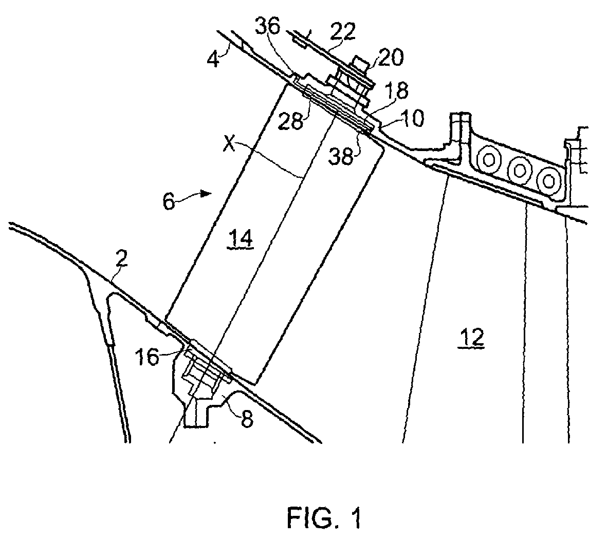
- Figure 1 shows an intake region of a compressor stage, for example an intermediate pressure stage, of a gas turbine engine.
- a flow path for working fluid is defined by an inner casing 2 and an outer casing 4.
- a variable inlet guide vane 6 is supported at each end by support structures in the form of bearing housings 8, 10 forming part of the inner and outer casings 2, 4. Downstream of the vane 6 there is a rotor represented by a blade 12, and it will be appreciated that further stator vanes and rotors follow the rotor 12.
- the vane 6 is one of an array of vanes distributed around the axis of the engine.
- Each vane has an aerofoil portion 14 which extends across the path of the working fluid (air).
- the aerofoil portion has a journal 16, 18 which is supported in the respective bearing housing 8, 10.
- the vane 6 has a spindle 20 to which an operating arm 22 is rigidly fastened.
- the operating arms 22 are connected at their ends away from the spindle 20, to a common ring which surrounds the engine and which can be turned about the axis of the engine to pivot the vanes 6 about their respective lengthwise axes X.
- the radially outer journal 18 is shown in more detail in Figure 2 . It will be appreciated that the journal 18 comprises two cylindrical portions 24, 26 which define between them a circumferential recess 28. The bottom of the recess is defined by a cylindrical connecting portion 30 which extends between the circumferential portions 24, 26 and is co-axial with the spindle 20.
- the spindle 20 extends from one face of the radially outer cylindrical portion 26, and the aerofoil portion 14 extends from the inwardly directed face 32 of the radially inner cylindrical portion 24.
- An aperture 34 in the form of a nozzle extends through the radially inner cylindrical portion 24, and so provides communication between the recess 28 and the flow path through the engine.
- the bearing housing 10 has a passage 36 which extends from a cylindrical cavity 38 in the bearing housing 10 to the exterior of the casing 4.
- the passage 36 is connected by suitable pipe work to a downstream region of the compressor stage, for example to stage 8 of the intermediate pressure compressor so that pressurised, and therefore heated, IP8 air is supplied to the cavity 38.
- the passage 36 opens into the cavity 38 at the location of the circumferential recess 28 in the journal 18 so that the heated air can enter the recess 28 from the passage 36 and then exit the recess 28 through the nozzle 34.
- Control means may be provided for controlling the flow rate of the heated air, or for closing the passage 36.
- the nozzle 34 opens at the face 32 at a port situated adjacent the aerofoil portion 14.
- the port of the aperture 34 is situated directly adjacent one side of the aerofoil portion 14, preferably the pressure side.
- the port is also situated close to the leading edge 40 of the aerofoil portion 14.
- the port of the aperture 34 extends into a transitional surface 42 over which the surface of the aerofoil portion 14 merges into the face 32 of the cylindrical portion 24.
- the hot air bleed from the IP8 compressor stage will be directed as a jet radially inwardly over the external surface, and specifically the pressure side, of the aerofoil portion 14. This will heat the aerofoil portion 14, so avoiding the accumulation of ice.
- the nozzle 34 may be differently configured, or may be one of an array of two or more nozzles, to provide a desired flow pattern of heated air over the external surface of the aerofoil portion 14.
- the cylindrical portions 24, 26 are provided with grooves 44 for receiving sealing rings, for example of carbon, for providing a seal between the cylindrical portions 24, 26 and the cylindrical wall of the cavity 38, so as to prevent unwanted air leakage from the recess 28.
- sealing rings for example of carbon
- the cylindrical portions 24, 26 have the same diameter as each other, and so present the same surface area to the pressurised air in the recess 28. Consequently, the loading on the journal 18 from the pressurised air is equal in both directions, avoiding the imposition of any radially inward or outward loading on the vane 6.
Landscapes
- Engineering & Computer Science (AREA)
- Mechanical Engineering (AREA)
- General Engineering & Computer Science (AREA)
- Chemical & Material Sciences (AREA)
- Combustion & Propulsion (AREA)
- Physics & Mathematics (AREA)
- Thermal Sciences (AREA)
- Structures Of Non-Positive Displacement Pumps (AREA)
- Turbine Rotor Nozzle Sealing (AREA)
- Control Of Turbines (AREA)
Abstract
Description
- This invention relates to a variable stator vane, and particularly, although not exclusively, to such a vane in the form of a variable inlet guide vane of a gas turbine engine.
- Variable stator vanes are mounted in a gas turbine engine in a manner which enables them to be pivoted about an axis extending generally lengthwise of the vane, so that the vanes can be turned about the axis to vary their angle of incidence with respect to the incoming air. This enables the vanes to be positioned appropriately for the prevailing operating conditions of the engine.
- Variable stator vanes, particularly those situated at the engine inlet, are prone to the accretion of ice on them. This can adversely affect the aerodynamic properties of the vane, and also fragments of accumulated ice may detach from the vane and cause damage to downstream components of the engine. It is therefore desirable to avoid such ice accretion.
- According to the present invention there is provided a variable stator vane comprising an aerofoil portion having at one end a journal for supporting the vane in a support structure, the journal having a circumferential recess and an aperture extending from the recess to a face of the journal directed towards the aerofoil portion, whereby heated air admitted to the recess is discharged from the aperture towards the aerofoil portion.
- A vane in accordance with the present invention can thus be heated during operation of the engine in which it is installed, so preventing the formation of ice on the vane, or melting any ice which has formed.
- The aperture may be configured to discharge air towards the pressure side of the aerofoil portion, and may therefore be disposed adjacent to the pressure side. The aperture may open at a port in the face of the journal directed towards the aerofoil portion, and the port may extend into a transition surface at which the surface of the aerofoil portion merges into the adjacent face of the journal. The port may be situated adjacent the leading edge of the aerofoil portion.
- The journal may be provided with sealing rings disposed on opposite sides of the recess, for providing a seal between the journal and a bearing surface provided in the support structure. The sealing rings may comprise carbon rings.
- The circumferential recess may be defined between cylindrical portions of the journal, the cylindrical portions having the same diameter as each other. As a result, the pressure applied to the cylindrical portions by heated air within the circumferential recess exerts an equal force on each cylindrical portion.
- The stator vane may be a variable inlet guide vane.
- The present invention also provides a gas turbine engine having a variable stator vane as defined above, the gas turbine engine having a support structure provided with a cylindrical cavity in which the journal is disposed. The support structure may have a passage for admitting heated air to the cavity at the location of the circumferential recess in the journal. The gas turbine engine may be provided with means for conveying the heated air from a source of heated air to the passage. The source of heated air may be a compressor stage of the gas turbine engine.
- For a better understanding of the present invention, and to show more clearly how it may be carried into effect, reference will now be made, by way of example, to the accompanying drawings, in which:
-
Figure 1 shows a variable inlet guide vane installed in a gas turbine engine; and -
Figure 2 shows, on an enlarged scale, part of the variable inlet guide vane ofFigure 1 . -
Figure 1 shows an intake region of a compressor stage, for example an intermediate pressure stage, of a gas turbine engine. A flow path for working fluid is defined by aninner casing 2 and an outer casing 4. A variableinlet guide vane 6 is supported at each end by support structures in the form of bearinghousings 8, 10 forming part of the inner andouter casings 2, 4. Downstream of thevane 6 there is a rotor represented by ablade 12, and it will be appreciated that further stator vanes and rotors follow therotor 12. - It will be appreciated that the
vane 6 is one of an array of vanes distributed around the axis of the engine. Each vane has anaerofoil portion 14 which extends across the path of the working fluid (air). At each end, the aerofoil portion has ajournal housing 8, 10. At its radially outer end, thevane 6 has aspindle 20 to which anoperating arm 22 is rigidly fastened. Theoperating arms 22 are connected at their ends away from thespindle 20, to a common ring which surrounds the engine and which can be turned about the axis of the engine to pivot thevanes 6 about their respective lengthwise axes X. - The radially
outer journal 18 is shown in more detail inFigure 2 . It will be appreciated that thejournal 18 comprises twocylindrical portions circumferential recess 28. The bottom of the recess is defined by a cylindrical connectingportion 30 which extends between thecircumferential portions spindle 20. Thespindle 20 extends from one face of the radially outercylindrical portion 26, and theaerofoil portion 14 extends from the inwardly directedface 32 of the radially innercylindrical portion 24. - An
aperture 34 in the form of a nozzle extends through the radially innercylindrical portion 24, and so provides communication between therecess 28 and the flow path through the engine. As shown inFigure 1 , thebearing housing 10 has apassage 36 which extends from acylindrical cavity 38 in thebearing housing 10 to the exterior of the casing 4. Although not shown, thepassage 36 is connected by suitable pipe work to a downstream region of the compressor stage, for example to stage 8 of the intermediate pressure compressor so that pressurised, and therefore heated, IP8 air is supplied to thecavity 38. Thepassage 36 opens into thecavity 38 at the location of thecircumferential recess 28 in thejournal 18 so that the heated air can enter therecess 28 from thepassage 36 and then exit therecess 28 through thenozzle 34. Control means may be provided for controlling the flow rate of the heated air, or for closing thepassage 36. - The
nozzle 34 opens at theface 32 at a port situated adjacent theaerofoil portion 14. As shown inFigure 2 the port of theaperture 34 is situated directly adjacent one side of theaerofoil portion 14, preferably the pressure side. The port is also situated close to the leadingedge 40 of theaerofoil portion 14. In particular, it will be appreciated fromFigure 2 that the port of theaperture 34 extends into atransitional surface 42 over which the surface of theaerofoil portion 14 merges into theface 32 of thecylindrical portion 24. - It will be appreciated that, with appropriate control of the pressure of air admitted to the
recess 28 and appropriate configuration of thenozzle 34, the hot air bleed from the IP8 compressor stage will be directed as a jet radially inwardly over the external surface, and specifically the pressure side, of theaerofoil portion 14. This will heat theaerofoil portion 14, so avoiding the accumulation of ice. It will be appreciated that thenozzle 34 may be differently configured, or may be one of an array of two or more nozzles, to provide a desired flow pattern of heated air over the external surface of theaerofoil portion 14. - The
cylindrical portions grooves 44 for receiving sealing rings, for example of carbon, for providing a seal between thecylindrical portions cavity 38, so as to prevent unwanted air leakage from therecess 28. - The
cylindrical portions recess 28. Consequently, the loading on thejournal 18 from the pressurised air is equal in both directions, avoiding the imposition of any radially inward or outward loading on thevane 6.
Claims (13)
- A variable stator vane (6) comprising an aerofoil portion (14) having at one end a journal (18) for supporting the vane (6) in a support structure (8,10), the journal (18) having a circumferential recess (28) and an aperture (34) extending from the recess (28) to a face of the journal (18) directed towards the aerofoil portion (14), whereby heated air admitted to the recess (28) is discharged from the aperture (34) towards the aerofoil portion (14).
- A variable stator vane (6) as claimed in claim 1, in which the aperture (34) is configured to discharge heated air towards the pressure side of the aerofoil portion (14).
- A variable stator vane (6) as claimed in claim 2, in which the aperture (34) is situated adjacent to the pressure side of the aerofoil portion (14).
- A variable stator vane (6) as claimed in anyone of the preceding claims, in which the aperture (34) opens at a port in the face of the journal (18) directed towards the aerofoil portion (14), the port extending into a transition surface between the surface of the aerofoil portion (14) and the face of the journal.
- A variable stator vane (6) as claimed in claim 4, in which the port is situated adjacent the leading edge (40) of the aerofoil portion (14).
- A variable stator vane (6) as claimed in any one of the preceding claims, in which the journal (18) is provided with sealing rings disposed on opposite sides of the recess (28).
- A variable stator vane (6) as claimed in claim 6, in which the sealing rings are carbon rings.
- A variable stator vane (6) as claimed in any one of the preceding claims, in which the circumferential recess (28) is defined between cylindrical portions (24,26) of the journal (18), the cylindrical portions (24,26) having the same diameter as each other.
- A variable stator vane (6) as claimed in any one of the preceding claims, in which the stator vane (6) is a variable inlet guide vane.
- A gas turbine engine having a variable stator vane (6) in accordance with any one of the preceding claims, the gas turbine engine having a support structure (8,10) provided with a cylindrical cavity (38) in which the journal (18) is disposed.
- A gas turbine engine as claimed in claim 10, in which the support structure (8,10) has a passage (36) for admitting heated air to the cavity (38) at a location adjacent the circumferential recess (28).
- A gas turbine engine as claimed in claim 11, in which means is provided for conveying heated air from a source of heated air to the passage (36).
- A gas turbine engine as claimed in claim 12, in which the source of heated air is a compressor stage of the gas turbine engine.
Applications Claiming Priority (1)
| Application Number | Priority Date | Filing Date | Title |
|---|---|---|---|
| GB0807359A GB2459462B (en) | 2008-04-23 | 2008-04-23 | A variable stator vane |
Publications (2)
| Publication Number | Publication Date |
|---|---|
| EP2112331A2 true EP2112331A2 (en) | 2009-10-28 |
| EP2112331A3 EP2112331A3 (en) | 2010-12-01 |
Family
ID=39494073
Family Applications (1)
| Application Number | Title | Priority Date | Filing Date |
|---|---|---|---|
| EP09250411A Withdrawn EP2112331A3 (en) | 2008-04-23 | 2009-02-16 | Variable stator vane and gas turbine engine comprising such a vane |
Country Status (3)
| Country | Link |
|---|---|
| US (1) | US8734088B2 (en) |
| EP (1) | EP2112331A3 (en) |
| GB (1) | GB2459462B (en) |
Families Citing this family (8)
| Publication number | Priority date | Publication date | Assignee | Title |
|---|---|---|---|---|
| EP2799717B1 (en) * | 2009-07-20 | 2019-10-09 | Ingersoll-Rand Company | System for an inlet guide vane assembly |
| CN102713304B (en) | 2009-11-03 | 2015-01-28 | 英格索尔-兰德公司 | Compressor inlet guide vanes |
| EP2623717A1 (en) * | 2012-02-02 | 2013-08-07 | Siemens Aktiengesellschaft | Blade ring for an axial turbo engine and method for adjusting the absorption characteristics of the blade ring |
| WO2015050730A1 (en) * | 2013-10-03 | 2015-04-09 | United Technologies Corporation | Rotating turbine vane bearing cooling |
| CN104100305B (en) * | 2014-07-22 | 2016-01-27 | 哈尔滨工程大学 | A kind of large meridian expansion variable geometry turbine with orthogonal type adjustable stator blade |
| US10208619B2 (en) | 2015-11-02 | 2019-02-19 | Florida Turbine Technologies, Inc. | Variable low turbine vane with aft rotation axis |
| DE102016207212A1 (en) * | 2016-04-28 | 2017-11-02 | MTU Aero Engines AG | Guide vane ring for a turbomachine |
| CN113530888B (en) * | 2021-08-24 | 2022-08-09 | 中国航发湖南动力机械研究所 | Multi-cavity integrated guide vane casing structure with anti-icing function |
Citations (2)
| Publication number | Priority date | Publication date | Assignee | Title |
|---|---|---|---|---|
| US3123283A (en) | 1962-12-07 | 1964-03-03 | Anti-icing valve means | |
| EP1998025A1 (en) | 2007-05-30 | 2008-12-03 | Snecma | Compressor with air re-injection |
Family Cites Families (7)
| Publication number | Priority date | Publication date | Assignee | Title |
|---|---|---|---|---|
| GB1012909A (en) * | 1962-12-07 | 1965-12-08 | Gen Electric | Improvements in anti-icing means for the compressor of a gas turbine engine |
| US3864058A (en) * | 1973-02-05 | 1975-02-04 | Garrett Corp | Cooled aerodynamic device |
| CA1115639A (en) * | 1979-02-23 | 1982-01-05 | Delmer H. Landis, Jr. | Floating seal for a variable area turbine nozzle |
| GB2210935B (en) * | 1987-10-10 | 1992-05-27 | Rolls Royce Plc | Variable stator vane assembly |
| US4856962A (en) * | 1988-02-24 | 1989-08-15 | United Technologies Corporation | Variable inlet guide vane |
| US20060062499A1 (en) * | 2004-04-08 | 2006-03-23 | Boyd Gary L | Integrated hydrodynamic air bearing and seal |
| DE102004030597A1 (en) * | 2004-06-24 | 2006-01-26 | Rolls-Royce Deutschland Ltd & Co Kg | Turbomachine with external wheel jet generation at the stator |
-
2008
- 2008-04-23 GB GB0807359A patent/GB2459462B/en not_active Expired - Fee Related
-
2009
- 2009-02-16 EP EP09250411A patent/EP2112331A3/en not_active Withdrawn
- 2009-02-23 US US12/379,466 patent/US8734088B2/en not_active Expired - Fee Related
Patent Citations (2)
| Publication number | Priority date | Publication date | Assignee | Title |
|---|---|---|---|---|
| US3123283A (en) | 1962-12-07 | 1964-03-03 | Anti-icing valve means | |
| EP1998025A1 (en) | 2007-05-30 | 2008-12-03 | Snecma | Compressor with air re-injection |
Also Published As
| Publication number | Publication date |
|---|---|
| GB2459462B (en) | 2010-09-01 |
| GB0807359D0 (en) | 2008-05-28 |
| US8734088B2 (en) | 2014-05-27 |
| US20090269187A1 (en) | 2009-10-29 |
| GB2459462A (en) | 2009-10-28 |
| EP2112331A3 (en) | 2010-12-01 |
Similar Documents
| Publication | Publication Date | Title |
|---|---|---|
| CN102454431B (en) | Variable turbine nozzle system | |
| US8734088B2 (en) | Variable stator vane | |
| CN103016072B (en) | With the turbosupercharger of the labyrinth sealed variable-nozzle had for blade | |
| JP6739934B2 (en) | Gas turbine seals | |
| CN102562653B (en) | System and method for running compressor | |
| CN112211728B (en) | Fuel conditioning for turbine engines | |
| US20200277862A1 (en) | Airfoil for a turbine engine | |
| EP3060764B1 (en) | Incident tolerant turbine vane cooling | |
| US11230935B2 (en) | Stator component cooling | |
| EP2964960B1 (en) | Gas turbine engine centrifugal compressor with seal between two diffuser parts | |
| CN109083690B (en) | Turbine engine with variable effective throat | |
| CN101532507A (en) | Adjustable compressor air extraction system and method | |
| CN107044447A (en) | Deicer for the shunting nose of axial flow impeller machine compressor | |
| CN106687666A (en) | Axi-centrifugal compressor with variable outlet guide vanes | |
| CN101575990A (en) | Turbocharger with variable nozzle having vane sealing surfaces | |
| JP4215993B2 (en) | Method and apparatus for operating a gas turbine engine | |
| KR20140038453A (en) | Variable-pitch nozzle for a radial flow turbine, in particular for a turbine of an auxiliary power source | |
| CN102562665B (en) | Axial compressor | |
| CN105715310A (en) | Engine and method for operating the same | |
| EP2612992B1 (en) | Turbine and method for separating particulates from a fluid | |
| EP2604801B1 (en) | Stator blade ring and method of making the ring | |
| JP2008151137A (en) | System for supplying air to vehicle and turbofan engine | |
| CN107084006B (en) | Accelerator insert for a gas turbine engine airfoil | |
| CN113757153B (en) | Systems and methods for regulating airflow into bores of a rotor to control blade tip clearances | |
| CN115885091A (en) | Turbine with pressurized cavity |
Legal Events
| Date | Code | Title | Description |
|---|---|---|---|
| PUAI | Public reference made under article 153(3) epc to a published international application that has entered the european phase |
Free format text: ORIGINAL CODE: 0009012 |
|
| AK | Designated contracting states |
Kind code of ref document: A2 Designated state(s): AT BE BG CH CY CZ DE DK EE ES FI FR GB GR HR HU IE IS IT LI LT LU LV MC MK MT NL NO PL PT RO SE SI SK TR |
|
| AX | Request for extension of the european patent |
Extension state: AL BA RS |
|
| PUAL | Search report despatched |
Free format text: ORIGINAL CODE: 0009013 |
|
| AK | Designated contracting states |
Kind code of ref document: A3 Designated state(s): AT BE BG CH CY CZ DE DK EE ES FI FR GB GR HR HU IE IS IT LI LT LU LV MC MK MT NL NO PL PT RO SE SI SK TR |
|
| AX | Request for extension of the european patent |
Extension state: AL BA RS |
|
| RIC1 | Information provided on ipc code assigned before grant |
Ipc: F02C 7/047 20060101ALI20101022BHEP Ipc: F02C 6/08 20060101ALI20101022BHEP Ipc: F04D 29/56 20060101ALI20101022BHEP Ipc: F01D 25/02 20060101ALI20101022BHEP Ipc: F02C 7/045 20060101ALI20101022BHEP Ipc: F01D 17/16 20060101AFI20090323BHEP |
|
| 17P | Request for examination filed |
Effective date: 20110414 |
|
| AKX | Designation fees paid |
Designated state(s): DE FR GB |
|
| RAP1 | Party data changed (applicant data changed or rights of an application transferred) |
Owner name: ROLLS-ROYCE PLC |
|
| STAA | Information on the status of an ep patent application or granted ep patent |
Free format text: STATUS: THE APPLICATION HAS BEEN WITHDRAWN |
|
| 18W | Application withdrawn |
Effective date: 20161017 |