EP2112316A2 - Pair of pre-cabled posts for sliding or swing gates - Google Patents
Pair of pre-cabled posts for sliding or swing gates Download PDFInfo
- Publication number
- EP2112316A2 EP2112316A2 EP09153408A EP09153408A EP2112316A2 EP 2112316 A2 EP2112316 A2 EP 2112316A2 EP 09153408 A EP09153408 A EP 09153408A EP 09153408 A EP09153408 A EP 09153408A EP 2112316 A2 EP2112316 A2 EP 2112316A2
- Authority
- EP
- European Patent Office
- Prior art keywords
- post
- pair
- gate
- ecu
- posts
- Prior art date
- Legal status (The legal status is an assumption and is not a legal conclusion. Google has not performed a legal analysis and makes no representation as to the accuracy of the status listed.)
- Withdrawn
Links
Images


Classifications
-
- E—FIXED CONSTRUCTIONS
- E05—LOCKS; KEYS; WINDOW OR DOOR FITTINGS; SAFES
- E05F—DEVICES FOR MOVING WINGS INTO OPEN OR CLOSED POSITION; CHECKS FOR WINGS; WING FITTINGS NOT OTHERWISE PROVIDED FOR, CONCERNED WITH THE FUNCTIONING OF THE WING
- E05F15/00—Power-operated mechanisms for wings
- E05F15/60—Power-operated mechanisms for wings using electrical actuators
- E05F15/603—Power-operated mechanisms for wings using electrical actuators using rotary electromotors
- E05F15/611—Power-operated mechanisms for wings using electrical actuators using rotary electromotors for swinging wings
- E05F15/616—Power-operated mechanisms for wings using electrical actuators using rotary electromotors for swinging wings operated by push-pull mechanisms
-
- E—FIXED CONSTRUCTIONS
- E05—LOCKS; KEYS; WINDOW OR DOOR FITTINGS; SAFES
- E05F—DEVICES FOR MOVING WINGS INTO OPEN OR CLOSED POSITION; CHECKS FOR WINGS; WING FITTINGS NOT OTHERWISE PROVIDED FOR, CONCERNED WITH THE FUNCTIONING OF THE WING
- E05F15/00—Power-operated mechanisms for wings
- E05F15/40—Safety devices, e.g. detection of obstructions or end positions
- E05F15/42—Detection using safety edges
- E05F15/43—Detection using safety edges responsive to disruption of energy beams, e.g. light or sound
-
- E—FIXED CONSTRUCTIONS
- E05—LOCKS; KEYS; WINDOW OR DOOR FITTINGS; SAFES
- E05F—DEVICES FOR MOVING WINGS INTO OPEN OR CLOSED POSITION; CHECKS FOR WINGS; WING FITTINGS NOT OTHERWISE PROVIDED FOR, CONCERNED WITH THE FUNCTIONING OF THE WING
- E05F15/00—Power-operated mechanisms for wings
- E05F15/60—Power-operated mechanisms for wings using electrical actuators
- E05F15/603—Power-operated mechanisms for wings using electrical actuators using rotary electromotors
- E05F15/611—Power-operated mechanisms for wings using electrical actuators using rotary electromotors for swinging wings
- E05F15/63—Power-operated mechanisms for wings using electrical actuators using rotary electromotors for swinging wings operated by swinging arms
-
- E—FIXED CONSTRUCTIONS
- E05—LOCKS; KEYS; WINDOW OR DOOR FITTINGS; SAFES
- E05F—DEVICES FOR MOVING WINGS INTO OPEN OR CLOSED POSITION; CHECKS FOR WINGS; WING FITTINGS NOT OTHERWISE PROVIDED FOR, CONCERNED WITH THE FUNCTIONING OF THE WING
- E05F15/00—Power-operated mechanisms for wings
- E05F15/60—Power-operated mechanisms for wings using electrical actuators
- E05F15/603—Power-operated mechanisms for wings using electrical actuators using rotary electromotors
- E05F15/632—Power-operated mechanisms for wings using electrical actuators using rotary electromotors for horizontally-sliding wings
- E05F15/635—Power-operated mechanisms for wings using electrical actuators using rotary electromotors for horizontally-sliding wings operated by push-pull mechanisms, e.g. flexible or rigid rack-and-pinion arrangements
-
- E—FIXED CONSTRUCTIONS
- E05—LOCKS; KEYS; WINDOW OR DOOR FITTINGS; SAFES
- E05F—DEVICES FOR MOVING WINGS INTO OPEN OR CLOSED POSITION; CHECKS FOR WINGS; WING FITTINGS NOT OTHERWISE PROVIDED FOR, CONCERNED WITH THE FUNCTIONING OF THE WING
- E05F15/00—Power-operated mechanisms for wings
- E05F15/70—Power-operated mechanisms for wings with automatic actuation
- E05F15/73—Power-operated mechanisms for wings with automatic actuation responsive to movement or presence of persons or objects
- E05F15/74—Power-operated mechanisms for wings with automatic actuation responsive to movement or presence of persons or objects using photoelectric cells
-
- E—FIXED CONSTRUCTIONS
- E05—LOCKS; KEYS; WINDOW OR DOOR FITTINGS; SAFES
- E05F—DEVICES FOR MOVING WINGS INTO OPEN OR CLOSED POSITION; CHECKS FOR WINGS; WING FITTINGS NOT OTHERWISE PROVIDED FOR, CONCERNED WITH THE FUNCTIONING OF THE WING
- E05F15/00—Power-operated mechanisms for wings
-
- E—FIXED CONSTRUCTIONS
- E05—LOCKS; KEYS; WINDOW OR DOOR FITTINGS; SAFES
- E05F—DEVICES FOR MOVING WINGS INTO OPEN OR CLOSED POSITION; CHECKS FOR WINGS; WING FITTINGS NOT OTHERWISE PROVIDED FOR, CONCERNED WITH THE FUNCTIONING OF THE WING
- E05F15/00—Power-operated mechanisms for wings
- E05F15/40—Safety devices, e.g. detection of obstructions or end positions
- E05F15/42—Detection using safety edges
- E05F15/43—Detection using safety edges responsive to disruption of energy beams, e.g. light or sound
- E05F2015/434—Detection using safety edges responsive to disruption of energy beams, e.g. light or sound with cameras or optical sensors
-
- E—FIXED CONSTRUCTIONS
- E05—LOCKS; KEYS; WINDOW OR DOOR FITTINGS; SAFES
- E05Y—INDEXING SCHEME ASSOCIATED WITH SUBCLASSES E05D AND E05F, RELATING TO CONSTRUCTION ELEMENTS, ELECTRIC CONTROL, POWER SUPPLY, POWER SIGNAL OR TRANSMISSION, USER INTERFACES, MOUNTING OR COUPLING, DETAILS, ACCESSORIES, AUXILIARY OPERATIONS NOT OTHERWISE PROVIDED FOR, APPLICATION THEREOF
- E05Y2201/00—Constructional elements; Accessories therefor
- E05Y2201/10—Covers; Housings
- E05Y2201/11—Covers
-
- E—FIXED CONSTRUCTIONS
- E05—LOCKS; KEYS; WINDOW OR DOOR FITTINGS; SAFES
- E05Y—INDEXING SCHEME ASSOCIATED WITH SUBCLASSES E05D AND E05F, RELATING TO CONSTRUCTION ELEMENTS, ELECTRIC CONTROL, POWER SUPPLY, POWER SIGNAL OR TRANSMISSION, USER INTERFACES, MOUNTING OR COUPLING, DETAILS, ACCESSORIES, AUXILIARY OPERATIONS NOT OTHERWISE PROVIDED FOR, APPLICATION THEREOF
- E05Y2201/00—Constructional elements; Accessories therefor
- E05Y2201/40—Motors; Magnets; Springs; Weights; Accessories therefor
- E05Y2201/43—Motors
- E05Y2201/434—Electromotors; Details thereof
-
- E—FIXED CONSTRUCTIONS
- E05—LOCKS; KEYS; WINDOW OR DOOR FITTINGS; SAFES
- E05Y—INDEXING SCHEME ASSOCIATED WITH SUBCLASSES E05D AND E05F, RELATING TO CONSTRUCTION ELEMENTS, ELECTRIC CONTROL, POWER SUPPLY, POWER SIGNAL OR TRANSMISSION, USER INTERFACES, MOUNTING OR COUPLING, DETAILS, ACCESSORIES, AUXILIARY OPERATIONS NOT OTHERWISE PROVIDED FOR, APPLICATION THEREOF
- E05Y2400/00—Electronic control; Electrical power; Power supply; Power or signal transmission; User interfaces
- E05Y2400/80—User interfaces
- E05Y2400/81—Feedback to user, e.g. tactile
- E05Y2400/818—Visual
- E05Y2400/822—Light emitters, e.g. light emitting diodes [LED]
-
- E—FIXED CONSTRUCTIONS
- E05—LOCKS; KEYS; WINDOW OR DOOR FITTINGS; SAFES
- E05Y—INDEXING SCHEME ASSOCIATED WITH SUBCLASSES E05D AND E05F, RELATING TO CONSTRUCTION ELEMENTS, ELECTRIC CONTROL, POWER SUPPLY, POWER SIGNAL OR TRANSMISSION, USER INTERFACES, MOUNTING OR COUPLING, DETAILS, ACCESSORIES, AUXILIARY OPERATIONS NOT OTHERWISE PROVIDED FOR, APPLICATION THEREOF
- E05Y2400/00—Electronic control; Electrical power; Power supply; Power or signal transmission; User interfaces
- E05Y2400/80—User interfaces
- E05Y2400/81—Feedback to user, e.g. tactile
- E05Y2400/83—Travel information display
-
- E—FIXED CONSTRUCTIONS
- E05—LOCKS; KEYS; WINDOW OR DOOR FITTINGS; SAFES
- E05Y—INDEXING SCHEME ASSOCIATED WITH SUBCLASSES E05D AND E05F, RELATING TO CONSTRUCTION ELEMENTS, ELECTRIC CONTROL, POWER SUPPLY, POWER SIGNAL OR TRANSMISSION, USER INTERFACES, MOUNTING OR COUPLING, DETAILS, ACCESSORIES, AUXILIARY OPERATIONS NOT OTHERWISE PROVIDED FOR, APPLICATION THEREOF
- E05Y2600/00—Mounting or coupling arrangements for elements provided for in this subclass
- E05Y2600/40—Mounting location; Visibility of the elements
- E05Y2600/41—Concealed
-
- E—FIXED CONSTRUCTIONS
- E05—LOCKS; KEYS; WINDOW OR DOOR FITTINGS; SAFES
- E05Y—INDEXING SCHEME ASSOCIATED WITH SUBCLASSES E05D AND E05F, RELATING TO CONSTRUCTION ELEMENTS, ELECTRIC CONTROL, POWER SUPPLY, POWER SIGNAL OR TRANSMISSION, USER INTERFACES, MOUNTING OR COUPLING, DETAILS, ACCESSORIES, AUXILIARY OPERATIONS NOT OTHERWISE PROVIDED FOR, APPLICATION THEREOF
- E05Y2600/00—Mounting or coupling arrangements for elements provided for in this subclass
- E05Y2600/40—Mounting location; Visibility of the elements
- E05Y2600/45—Mounting location; Visibility of the elements in or on the fixed frame
-
- E—FIXED CONSTRUCTIONS
- E05—LOCKS; KEYS; WINDOW OR DOOR FITTINGS; SAFES
- E05Y—INDEXING SCHEME ASSOCIATED WITH SUBCLASSES E05D AND E05F, RELATING TO CONSTRUCTION ELEMENTS, ELECTRIC CONTROL, POWER SUPPLY, POWER SIGNAL OR TRANSMISSION, USER INTERFACES, MOUNTING OR COUPLING, DETAILS, ACCESSORIES, AUXILIARY OPERATIONS NOT OTHERWISE PROVIDED FOR, APPLICATION THEREOF
- E05Y2600/00—Mounting or coupling arrangements for elements provided for in this subclass
- E05Y2600/40—Mounting location; Visibility of the elements
- E05Y2600/452—Mounting location; Visibility of the elements in or on the floor or wall
-
- E—FIXED CONSTRUCTIONS
- E05—LOCKS; KEYS; WINDOW OR DOOR FITTINGS; SAFES
- E05Y—INDEXING SCHEME ASSOCIATED WITH SUBCLASSES E05D AND E05F, RELATING TO CONSTRUCTION ELEMENTS, ELECTRIC CONTROL, POWER SUPPLY, POWER SIGNAL OR TRANSMISSION, USER INTERFACES, MOUNTING OR COUPLING, DETAILS, ACCESSORIES, AUXILIARY OPERATIONS NOT OTHERWISE PROVIDED FOR, APPLICATION THEREOF
- E05Y2800/00—Details, accessories and auxiliary operations not otherwise provided for
- E05Y2800/20—Combinations of elements
- E05Y2800/205—Combinations of elements forming a unit
-
- E—FIXED CONSTRUCTIONS
- E05—LOCKS; KEYS; WINDOW OR DOOR FITTINGS; SAFES
- E05Y—INDEXING SCHEME ASSOCIATED WITH SUBCLASSES E05D AND E05F, RELATING TO CONSTRUCTION ELEMENTS, ELECTRIC CONTROL, POWER SUPPLY, POWER SIGNAL OR TRANSMISSION, USER INTERFACES, MOUNTING OR COUPLING, DETAILS, ACCESSORIES, AUXILIARY OPERATIONS NOT OTHERWISE PROVIDED FOR, APPLICATION THEREOF
- E05Y2800/00—Details, accessories and auxiliary operations not otherwise provided for
- E05Y2800/352—Frames; Posts
- E05Y2800/353—Frames; Posts fixed
- E05Y2800/358—Frames; Posts fixed vertical frame members or posts
-
- E—FIXED CONSTRUCTIONS
- E05—LOCKS; KEYS; WINDOW OR DOOR FITTINGS; SAFES
- E05Y—INDEXING SCHEME ASSOCIATED WITH SUBCLASSES E05D AND E05F, RELATING TO CONSTRUCTION ELEMENTS, ELECTRIC CONTROL, POWER SUPPLY, POWER SIGNAL OR TRANSMISSION, USER INTERFACES, MOUNTING OR COUPLING, DETAILS, ACCESSORIES, AUXILIARY OPERATIONS NOT OTHERWISE PROVIDED FOR, APPLICATION THEREOF
- E05Y2900/00—Application of doors, windows, wings or fittings thereof
- E05Y2900/40—Application of doors, windows, wings or fittings thereof for gates
Definitions
- the present invention relates to the automatic gate sector and refers in particular to a pair of pre-cabled posts for the realisation of a motorised sliding or swing gate.
- each closing device usually has its own motor system so that even within the same manufacturer there is a vast range of different automatisms with evident disadvantages for production costs, warehouse management, sales and servicing.
- the purpose of the present invention is to permit the realisation of motorised gates which can be rapidly and easily installed even by non-experts, of reduced size and simple and economical production.
- Another purpose of the invention is that of providing a pair of posts for motorised gates which are versatile and easy to adapt to numerous sizes of gate and applications.
- FIG. 1 is a schematic illustration of a pair of pre-cabled posts according to the invention.
- FIG. 2 shows one of the pre-cabled posts according to the invention, in a first example of application
- FIG. 3 shows one of the posts in a second example of application
- figure 3a shows a variation of the embodiment in figure 3 ;
- FIG. 4 shows one of the posts in a third example of application.
- FIG. 5 shows a kit for the control of the electric/electronic devices of the pair of posts.
- reference numeral 1 globally denotes a pair of pre-cabled posts for sliding or swing gates. Each post comprises a tubular body 18 open at the top.
- a first post 20a; 200a; 220a is fitted with an electronic control unit (ECU) 12 of at least a first electric actuator 10; 100; 110 able to move a respective leaf 30 of the gate, a presence sensor 28, and at least a first light signalling device 14.
- the presence sensor 28 is made, for example, with two photocells, each installed on a respective post of the pair of posts.
- the ECU 12 and the light signalling device 14 are attached to and extend from a support cover 16 able to close off the tubular body 18 of the first post of the gate at the top.
- the ECU 12 and the light signalling device 14 are connected to the cover 16 so as to be mounted on the first post 20a; 200a; 220a as a single body.
- a second post 20b is electrically connected or connectable to the ECU 12 by means of an electric cable 27, for example a multicore cable, which extends from the first post 20a; 200a; 220a, enters the tubular body 18 of the second post 20b at the bottom and terminates at the height of the sensor 28 and/or at a second electric actuator able to move a respective second leaf of the gate and/or at a second light signalling device 14b.
- an electric cable 27 for example a multicore cable, which extends from the first post 20a; 200a; 220a, enters the tubular body 18 of the second post 20b at the bottom and terminates at the height of the sensor 28 and/or at a second electric actuator able to move a respective second leaf of the gate and/or at a second light signalling device 14b.
- the electric cable 27 is inserted in a tubular element 27' able to protect the electric cable when it is laid underground.
- the tubular element 27' may be rigid, flexible (for instance a spiral wound cable) or telescopic, so as to adapt to varying distances between the two posts.
- the two posts are provided at the base with an electric socket or plug 27" for connection to the electric cable 27.
- the electric cable 27 and the outer tubular element 27' can therefore be supplied disconnected from the posts, if necessary cut to the right size in relation to the distance from the posts, and lastly connected to these at the moment of putting the gate into function, for example by qualified persons should existing legislation require so.
- the pair of posts 1 thus constitutes a pre-assembled and pre-cabled assembly ready to be positioned on site to then connect the leaf or leaves of a gate.
- the pair of posts may be supplied already with electric movement actuators of the leaves, if necessary pre-assembled on the posts, or predisposed to receive electric actuators suitable for the application, as shown in figure 1 .
- the pair of posts is supplied in a single pack comprising the two pre-cabled posts, in other words already fitted with at least one ECU, presence sensor, light signalling device, one or two electric actuators, depending on the application, the electric connection cable of the two posts, if necessary inserted in the tubular external protection element and the power supply cable.
- one advantage is that the pair of posts can be supplied to the automation company which can fit electric actuators made by various manufacturers depending on the application and on the performance.
- the pair of posts 1 may be made operative and functioning by merely connecting the two posts electrically and connecting them to an electric power source 60, for example a draw pit connected to the mains supply at 220 V, a power supply cable 61 which powers the ECU 12 and which comes out of the base of the first post.
- an electric power source 60 for example a draw pit connected to the mains supply at 220 V, a power supply cable 61 which powers the ECU 12 and which comes out of the base of the first post.
- the ECU 12 extends downwards from the cover 16 so as to be housed inside the tubular body 18 of the post.
- the light signalling device 14 rather extends upwards from the cover 16.
- the ECU 12 extends in a vertical plane so as to make the most of the depth of the cavity of the tubular body 18.
- the ECU 12 is attached to an L-shaped support bracket 22 which extends vertically from the cover 16.
- a single attachment element 24, for example a screw, goes through the cover 16 and contemporarily secures the support bracket 22 of the ECU 12 and the light signalling device 14 to the same cover. Consequently, the latter acts as a support element for the light signalling device 14 and for the ECU 12 as well as covering the tubular body of the post.
- the light signalling device 14 is electrically connected to the ECU 12 by electric cables passing through a hole made in the cover.
- a block 25 is attached containing an electronic lock connected to the ECU 12 to activate the electric actuator using a dedicated key.
- the ECU 12, light signalling device 14 and electronic lock 25 constitute an assembly already electronically cabled and mechanically assembled, ready for installation on the tubular body 18 and for connection to the electric power supply and the electric /electronic devices making the gate automatic.
- the ECU 12 can command one or two electric actuators 10; 100; 110.
- the second electric actuator is destined for installation on the other post of the gate, should the gate have two swing or sliding leaves.
- a first cable 26 extends for electric connection to a first electric actuator and a second cable 27, longer than the first, for the electric connection of the second actuator and/or the second photocell of the presence sensor 28, and/or the second light signalling device 14b.
- This second cable is, for example, of the type suitable for laying underground through a pipe.
- the ECU 12 is, moreover, able to receive limit position or encoder (not shown) impulses, for each electric actuator.
- each post is predisposed to receive a respective electric actuator, for example of the type shown in figure 4 , attached to the tubular body 18 by means of an anchor plate 111.
- the connection cables to the actuators are in this case taken to the point where the actuators will be mounted, for example to beside the plates 111.
- the cable 27 which electrically connects the second post to the first carries, as well as the power supply connections of the electric actuator and of any relative limit positions or encoders, connections of the photocell 28 and of the light signalling device 14b.
- the gate is of the type with at least one swing leaf 30.
- the electric actuator 10 is a gear motor system, for example working on a continuous voltage of 12 or 24 Volts, able to cause the rotation of a swing leaf 30.
- the gear motor system 10 is lodged in a special compartment 32 preferably attached to one side of the base of the tubular body 18.
- the compartment 32 is made so as to accommodate the gear motor system underground, enabling the extremity of the crankshaft 34 to protrude from the ground.
- joined to the gear motor system 10 are transmission devices of the movement from the crankshaft 34 to the leaf of the gate.
- said devices comprise a telescopic arm 36 having one extremity joined to the crankshaft 34 and the opposite extremity hinged to a leaf 30 of the gate.
- the electric actuator is a gear motor system 100 able to cause the translation of a sliding gate 300 fitted with rack 301.
- the gear motor system 100 extends horizontally inside the tubular body 18 letting the free extremity of the crankshaft 34 protrude.
- the gear motor system 100 comprises a body, fitted with an attachment flange 101 near the crankshaft exit, to a lateral surface of the tubular body 18 of the post. Splined onto the crankshaft is a cogwheel 102 able to mesh in the cogs of the rack 301.
- the post 200 comprises moreover a guide plate 302 able to support at the bottom a sliding leaf 300 of the gate.
- the pair of posts carry all the automation and support devices of the gate.
- the guide plate 302 of the sliding leaf 300 may be supplied together with the pair of posts, for example already welded to them.
- the gear motor system 100 is positioned outside the post 200, so that once installed, it is inside the property defined by the gate.
- Such gear motor system 100 fitted with its cogwheel 102, is lodged in its casing 103 and is connected or may be connected to the post 200 with its own electric cable 104.
- the electric actuator is a linear motor 110 having its body pivoted to an attachment plate 111 on the lateral surface of the tubular body 18 of the post and the stem pivoted to a leaf 330 of the gate.
- a ventilation aperture 5 is provided in the tubular body 10 to enable the ECU 12 to dissipate heat outside the tubular body 18.
- the pair of posts 1 make it possible to install a gate extremely rapidly and without the need for specialised personnel.
- the pair of posts 1 is supplied ready for installation with all the electrical equipment already fitted and with the electrical connections predisposed, requiring connection only.
- the installation of the gate requires solely the fixing of the posts in the ground, the laying underground of the electric cable connecting them and the fitting of the gates.
- the pair of pre-cabled posts can be used for numerous applications and can therefore be produced in large quantities with a consequent reduction of the costs of the gates.
- the production of a pair of pre-cabled posts also facilitates the subsequent compliance of the gate, in that at least part of the compliance tests can be performed by the post supplier before installation.
Landscapes
- Power-Operated Mechanisms For Wings (AREA)
- Gates (AREA)
- Breeding Of Plants And Reproduction By Means Of Culturing (AREA)
- High-Pressure Fuel Injection Pump Control (AREA)
Abstract
Description
- The present invention relates to the automatic gate sector and refers in particular to a pair of pre-cabled posts for the realisation of a motorised sliding or swing gate.
- Automatisms for moving gates are already known of and widely used. Such automatisms however are generally quite complex and expensive and require, for their installation and servicing, the presence of specialised technicians and many hours of work.
- Moreover the known automatisms often take up considerable space given that they require support and/or adaptive structures so as to attach them on site to or near the gate to which they are to be applied.
- Lastly, each closing device usually has its own motor system so that even within the same manufacturer there is a vast range of different automatisms with evident disadvantages for production costs, warehouse management, sales and servicing.
- The purpose of the present invention is to permit the realisation of motorised gates which can be rapidly and easily installed even by non-experts, of reduced size and simple and economical production.
- Another purpose of the invention is that of providing a pair of posts for motorised gates which are versatile and easy to adapt to numerous sizes of gate and applications.
- These purposes are achieved by a pair of posts according to claim 1.
- Further characteristics and advantages of the pair of posts according to the invention will be evident from the description below made by way of a non-limiting example of preferred embodiments, with reference to the attached figures wherein:
- -
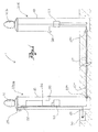
figure 1 is a schematic illustration of a pair of pre-cabled posts according to the invention; - -
figure 2 shows one of the pre-cabled posts according to the invention, in a first example of application; - -
figure 3 shows one of the posts in a second example of application; - -
figure 3a shows a variation of the embodiment infigure 3 ; - -
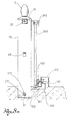
figure 4 shows one of the posts in a third example of application; and - -
figure 5 shows a kit for the control of the electric/electronic devices of the pair of posts. - In said drawings, reference numeral 1 globally denotes a pair of pre-cabled posts for sliding or swing gates. Each post comprises a
tubular body 18 open at the top. - A
first post 20a; 200a; 220a is fitted with an electronic control unit (ECU) 12 of at least a firstelectric actuator 10; 100; 110 able to move arespective leaf 30 of the gate, apresence sensor 28, and at least a firstlight signalling device 14. Thepresence sensor 28 is made, for example, with two photocells, each installed on a respective post of the pair of posts. - The
ECU 12 and thelight signalling device 14 are attached to and extend from asupport cover 16 able to close off thetubular body 18 of the first post of the gate at the top. - In other words, the
ECU 12 and thelight signalling device 14 are connected to thecover 16 so as to be mounted on thefirst post 20a; 200a; 220a as a single body. - A second post 20b is electrically connected or connectable to the
ECU 12 by means of anelectric cable 27, for example a multicore cable, which extends from thefirst post 20a; 200a; 220a, enters thetubular body 18 of the second post 20b at the bottom and terminates at the height of thesensor 28 and/or at a second electric actuator able to move a respective second leaf of the gate and/or at a secondlight signalling device 14b. - According to one embodiment, the
electric cable 27 is inserted in a tubular element 27' able to protect the electric cable when it is laid underground. The tubular element 27' may be rigid, flexible (for instance a spiral wound cable) or telescopic, so as to adapt to varying distances between the two posts. Advantageously, the two posts are provided at the base with an electric socket or plug 27" for connection to theelectric cable 27. Theelectric cable 27 and the outer tubular element 27' can therefore be supplied disconnected from the posts, if necessary cut to the right size in relation to the distance from the posts, and lastly connected to these at the moment of putting the gate into function, for example by qualified persons should existing legislation require so. - The pair of posts 1 thus constitutes a pre-assembled and pre-cabled assembly ready to be positioned on site to then connect the leaf or leaves of a gate.
- The pair of posts may be supplied already with electric movement actuators of the leaves, if necessary pre-assembled on the posts, or predisposed to receive electric actuators suitable for the application, as shown in
figure 1 . - In the former case one is thus dealing with a finished product, which requires only the mechanical connection f the electric actuators to the leaves of the gate, and therefore the services of personnel not specialised in gate automation. For example, according to one embodiment of the invention, the pair of posts is supplied in a single pack comprising the two pre-cabled posts, in other words already fitted with at least one ECU, presence sensor, light signalling device, one or two electric actuators, depending on the application, the electric connection cable of the two posts, if necessary inserted in the tubular external protection element and the power supply cable.
- In the second case one advantage is that the pair of posts can be supplied to the automation company which can fit electric actuators made by various manufacturers depending on the application and on the performance.
- In any case, once the electric actuators have been mounted, the pair of posts 1 may be made operative and functioning by merely connecting the two posts electrically and connecting them to an electric power source 60, for example a draw pit connected to the mains supply at 220 V, a
power supply cable 61 which powers the ECU 12 and which comes out of the base of the first post. - The ECU 12 extends downwards from the
cover 16 so as to be housed inside thetubular body 18 of the post. Thelight signalling device 14 rather extends upwards from thecover 16. - Preferably, the ECU 12 extends in a vertical plane so as to make the most of the depth of the cavity of the
tubular body 18. - According to one embodiment, the ECU 12 is attached to an L-
shaped support bracket 22 which extends vertically from thecover 16. - Advantageously, a
single attachment element 24, for example a screw, goes through thecover 16 and contemporarily secures thesupport bracket 22 of theECU 12 and thelight signalling device 14 to the same cover. Consequently, the latter acts as a support element for thelight signalling device 14 and for theECU 12 as well as covering the tubular body of the post. - The
light signalling device 14 is electrically connected to theECU 12 by electric cables passing through a hole made in the cover. - According to one advantageous embodiment, at one side of the
cover 16, ablock 25, is attached containing an electronic lock connected to theECU 12 to activate the electric actuator using a dedicated key. - As a result, the
ECU 12,light signalling device 14 andelectronic lock 25 constitute an assembly already electronically cabled and mechanically assembled, ready for installation on thetubular body 18 and for connection to the electric power supply and the electric /electronic devices making the gate automatic. - According to one embodiment, the ECU 12 can command one or two
electric actuators 10; 100; 110. The second electric actuator is destined for installation on the other post of the gate, should the gate have two swing or sliding leaves. - From the
ECU 12 therefore afirst cable 26 extends for electric connection to a first electric actuator and asecond cable 27, longer than the first, for the electric connection of the second actuator and/or the second photocell of thepresence sensor 28, and/or the secondlight signalling device 14b. This second cable is, for example, of the type suitable for laying underground through a pipe. - The
ECU 12 is, moreover, able to receive limit position or encoder (not shown) impulses, for each electric actuator. - In the schematic example shown in
figure 1 , each post is predisposed to receive a respective electric actuator, for example of the type shown infigure 4 , attached to thetubular body 18 by means of ananchor plate 111. The connection cables to the actuators are in this case taken to the point where the actuators will be mounted, for example to beside theplates 111. - It should be noted, in the example shown, that the
cable 27 which electrically connects the second post to the first carries, as well as the power supply connections of the electric actuator and of any relative limit positions or encoders, connections of thephotocell 28 and of thelight signalling device 14b. - According to an example of an application shown in
figure 2 , showing only the first of the two posts, the gate is of the type with at least oneswing leaf 30. In this example theelectric actuator 10 is a gear motor system, for example working on a continuous voltage of 12 or 24 Volts, able to cause the rotation of aswing leaf 30. - According to one embodiment, the
gear motor system 10, is lodged in aspecial compartment 32 preferably attached to one side of the base of thetubular body 18. According to one embodiment, thecompartment 32 is made so as to accommodate the gear motor system underground, enabling the extremity of thecrankshaft 34 to protrude from the ground. - According to one embodiment, joined to the
gear motor system 10 are transmission devices of the movement from thecrankshaft 34 to the leaf of the gate. For example, said devices comprise atelescopic arm 36 having one extremity joined to thecrankshaft 34 and the opposite extremity hinged to aleaf 30 of the gate. - In the application example shown in
figure 3 , the electric actuator is agear motor system 100 able to cause the translation of a slidinggate 300 fitted withrack 301. According to one embodiment, thegear motor system 100 extends horizontally inside thetubular body 18 letting the free extremity of thecrankshaft 34 protrude. Preferably, thegear motor system 100 comprises a body, fitted with anattachment flange 101 near the crankshaft exit, to a lateral surface of thetubular body 18 of the post. Splined onto the crankshaft is acogwheel 102 able to mesh in the cogs of therack 301. - In this application, the post 200 comprises moreover a
guide plate 302 able to support at the bottom a slidingleaf 300 of the gate. - It should be noted that in this embodiment of a sliding gate, the pair of posts carry all the automation and support devices of the gate.
- Advantageously, the
guide plate 302 of the slidingleaf 300 may be supplied together with the pair of posts, for example already welded to them. - In the embodiment variation shown in
figure 3a , thegear motor system 100 is positioned outside the post 200, so that once installed, it is inside the property defined by the gate. Suchgear motor system 100, fitted with itscogwheel 102, is lodged in itscasing 103 and is connected or may be connected to the post 200 with its ownelectric cable 104. - In the application example shown in
figure 4 , the electric actuator is alinear motor 110 having its body pivoted to anattachment plate 111 on the lateral surface of thetubular body 18 of the post and the stem pivoted to aleaf 330 of the gate. - In all the post embodiments, advantageously a
ventilation aperture 5 is provided in thetubular body 10 to enable theECU 12 to dissipate heat outside thetubular body 18. - In all the embodiments described, it is clear how the pair of posts 1 make it possible to install a gate extremely rapidly and without the need for specialised personnel. In fact, the pair of posts 1 is supplied ready for installation with all the electrical equipment already fitted and with the electrical connections predisposed, requiring connection only.
- Essentially, the installation of the gate requires solely the fixing of the posts in the ground, the laying underground of the electric cable connecting them and the fitting of the gates.
- Apart from the electric actuators, which are chosen on the basis of the application and the performance desired, the pair of pre-cabled posts can be used for numerous applications and can therefore be produced in large quantities with a consequent reduction of the costs of the gates.
- The production of a pair of pre-cabled posts also facilitates the subsequent compliance of the gate, in that at least part of the compliance tests can be performed by the post supplier before installation.
- A person skilled in the art may make modifications, adjustments and substitute elements with others functionally equivalent to the embodiments of the pair of posts described above so as to satisfy contingent requirements while remaining within the scope of protection as defined by the appended claims. Each of the characteristics described as belonging to one possible embodiment may be realised independently of the other embodiments described.
Claims (13)
- Pair of pre-cabled posts for sliding or swing gates, where each post comprises a tubular body open at the top, wherein:- a first post is fitted with an electronic control unit (ECU) and at least a first electric actuator able to move a respective leaf of the gate, a presence sensor and at least a first light signalling device,- said ECU and said first light signalling device are attached to and extend from a support cover able to seal the tubular body of said first post of the gate at the top,- a second post is electrically connected or connectable to the ECU by means of an electric cable which extends from the first post, entering the tubular body of the second post at the bottom and terminating at the height of the presence sensor and/or a second electric actuator able to move a respective second leaf of the gate and/or a second light signalling device.
- Pair of posts according to the previous claim, wherein the ECU extends downwards from the support cover so as to be housed inside the tubular body of the first post.
- Pair of posts according to claim 1 or 2, wherein the light signalling device extends upwards from the support cover.
- Pair of posts according to any of the previous claims, wherein the ECU is attached to the support cover so as extend mainly on a vertical plane.
- Pair of posts according to claim 4, wherein the ECU is attached to an L-shaped support bracket which extends vertically from the cover.
- Pair of posts according to any of the previous claims, wherein a single attachment element going through the cover secures the ECU and the light signalling device to the cover itself.
- Pair of posts according to any of the claims 1-6, wherein at least the first post comprises a gear motor system able to cause the rotation of a swing gate.
- Pair of posts according to claim 7, wherein the gear motor system is lodged in a compartment made on one side of the tubular body of the post, said compartment being positioned so as to be placed underground leaving the free end of the crankshaft to protrude from the ground.
- Pair of posts according to claim 7, wherein the gear motor system is lodged in a seat made inside the tubular body so as to let the free end of the crankshaft protrude from said tubular body, a cogwheel being splined to the crankshaft able to mesh with the teeth of a rack joined to a leaf of the gate.
- Pair of posts according to claim 9, wherein at least one post comprises, in addition, a guide plate able to support in a sliding manner a sliding leaf of the gate.
- Control kit of the electric/electronic devices of at least one motorised post of a gate, where said post comprises a tubular body, comprising at least one electronic control unit (ECU) for an electric actuator able to move the respective leaf of the gate and a light signalling device able to indicate the activation of said electric actuator, characterised by the fact that said ECU and said light signalling device are connected to the cover on the top of the tubular body of the post, so as to be fitted to the post as a single body.
- Kit according to claim 11, wherein on one side of the cover is a block containing an electronic lock connected to the ECU.
- Method of assembly of a motorised gate comprising the phases of:- supplying a pair of pre-cabled posts according to any of the claims 1-10;- positioning the posts;- connecting the leaf or leaves of the gate to the respective posts;- connecting at least one electric actuator to the respective leaf.
Applications Claiming Priority (1)
| Application Number | Priority Date | Filing Date | Title |
|---|---|---|---|
| IT000087A ITBS20080087A1 (en) | 2008-04-22 | 2008-04-22 | PAIR OF PRECABLATE PLANTS FOR SLIDING OR SWING GATES |
Publications (2)
| Publication Number | Publication Date |
|---|---|
| EP2112316A2 true EP2112316A2 (en) | 2009-10-28 |
| EP2112316A3 EP2112316A3 (en) | 2010-05-05 |
Family
ID=40296716
Family Applications (1)
| Application Number | Title | Priority Date | Filing Date |
|---|---|---|---|
| EP09153408A Withdrawn EP2112316A3 (en) | 2008-04-22 | 2009-02-23 | Pair of pre-cabled posts for sliding or swing gates |
Country Status (2)
| Country | Link |
|---|---|
| EP (1) | EP2112316A3 (en) |
| IT (1) | ITBS20080087A1 (en) |
Cited By (6)
| Publication number | Priority date | Publication date | Assignee | Title |
|---|---|---|---|---|
| FR2962756A1 (en) * | 2010-07-15 | 2012-01-20 | Espes Sa | Motorized doorway e.g. motorized sliding doorway, for industrial site, has motor block fixed to plate and connected with rod, so that position variation of rod causes translation movement of plate to cause pinion translation movement |
| FR3003890A1 (en) * | 2013-03-29 | 2014-10-03 | Michel Gelin | LIGHTING SECURITY DEVICE FOR PORTAL |
| EP2840217A1 (en) * | 2013-08-23 | 2015-02-25 | Samir Sahrane | Automatic external portal with at least one scanner for detecting the presence of at least one object in the vicinity of the portal |
| WO2016076752A1 (en) * | 2014-11-13 | 2016-05-19 | Алексей Юрьевич РУДЕНКО | Automatic drive for hinged gates |
| WO2016139689A1 (en) * | 2015-03-04 | 2016-09-09 | Zumpano Eugenio | A device for moving gates sliding along curved trajectories |
| EP2754828A3 (en) * | 2013-01-14 | 2018-01-03 | dormakaba Deutschland GmbH | Intermediate element for connecting two assemblies mounted on a door leaf assembly |
Family Cites Families (5)
| Publication number | Priority date | Publication date | Assignee | Title |
|---|---|---|---|---|
| US4665650A (en) * | 1986-05-12 | 1987-05-19 | Hall Richard C | Control gate assembly |
| CA2392303C (en) * | 2001-07-24 | 2005-07-12 | Pierre Gagnon | Transportable one piece modular automatic entry gate |
| US7023162B2 (en) * | 2003-02-18 | 2006-04-04 | The Chamberlain Group, Inc. | Automatic gate operator |
| FR2855551B1 (en) * | 2003-05-28 | 2005-07-15 | Doitrand Ets | MULTI-FUNCTION PORTAL PILLAR |
| DE102005051722A1 (en) * | 2005-10-27 | 2007-05-10 | Elka Torantriebe Gmbh & Co. Betriebs Kg | Swivel drive for rotary door leaf, has retainer accommodated in inner portion of door post, where retainer is inserted into opened lower front end of gate post during attachment of gate post on base plate |
-
2008
- 2008-04-22 IT IT000087A patent/ITBS20080087A1/en unknown
-
2009
- 2009-02-23 EP EP09153408A patent/EP2112316A3/en not_active Withdrawn
Cited By (9)
| Publication number | Priority date | Publication date | Assignee | Title |
|---|---|---|---|---|
| FR2962756A1 (en) * | 2010-07-15 | 2012-01-20 | Espes Sa | Motorized doorway e.g. motorized sliding doorway, for industrial site, has motor block fixed to plate and connected with rod, so that position variation of rod causes translation movement of plate to cause pinion translation movement |
| EP2754828A3 (en) * | 2013-01-14 | 2018-01-03 | dormakaba Deutschland GmbH | Intermediate element for connecting two assemblies mounted on a door leaf assembly |
| FR3003890A1 (en) * | 2013-03-29 | 2014-10-03 | Michel Gelin | LIGHTING SECURITY DEVICE FOR PORTAL |
| EP2803803A1 (en) * | 2013-03-29 | 2014-11-19 | Michel Gelin | Luminous safety device for gate |
| EP2840217A1 (en) * | 2013-08-23 | 2015-02-25 | Samir Sahrane | Automatic external portal with at least one scanner for detecting the presence of at least one object in the vicinity of the portal |
| FR3009837A1 (en) * | 2013-08-23 | 2015-02-27 | Sodispro | AUTOMATIC OUTDOOR GATE WITH AT LEAST ONE SCANNER DETECTING THE PRESENCE OF AT LEAST ONE OBJECT NEAR THE PORTAL |
| EP2840217B1 (en) | 2013-08-23 | 2018-09-12 | Samir Sahrane | Automatic external portal with at least one scanner for detecting the presence of at least one object in the vicinity of the portal |
| WO2016076752A1 (en) * | 2014-11-13 | 2016-05-19 | Алексей Юрьевич РУДЕНКО | Automatic drive for hinged gates |
| WO2016139689A1 (en) * | 2015-03-04 | 2016-09-09 | Zumpano Eugenio | A device for moving gates sliding along curved trajectories |
Also Published As
| Publication number | Publication date |
|---|---|
| EP2112316A3 (en) | 2010-05-05 |
| ITBS20080087A1 (en) | 2009-10-23 |
Similar Documents
| Publication | Publication Date | Title |
|---|---|---|
| EP2112316A2 (en) | Pair of pre-cabled posts for sliding or swing gates | |
| CA2686013C (en) | Apparatus and method pertaining to a pre-configured post for use with an automatically-movable barrier | |
| US20090193717A1 (en) | Operator system for an aperture member | |
| KR20230143614A (en) | Door system with routed wire harness for connection to electrical devices inside the door and external door frame | |
| US7005973B2 (en) | Electrical actuator assembly for hinged vehicle safety devices | |
| US20100319257A1 (en) | High torque movable barrier actuation at low speeds utilizing a hub motor | |
| KR101326006B1 (en) | Buried under earth type switch box with vacuum apparatus | |
| US11715998B2 (en) | Switching device for switching an electric motor | |
| CN112350164A (en) | Automatically controlled cabinet of regulation type environmental control | |
| US20070246324A1 (en) | Driving Device For Passage Gates Or Thorougfare Gates And Door Or Gate Drives | |
| CA2205747A1 (en) | Sealed electrical actuator assembly for hinged vehicle safety devices | |
| EP1947278A1 (en) | Electronic system for controlling gate or door opening | |
| CN121464257A (en) | Barrier shell and upright post for barrier | |
| NO762487L (en) | ||
| CN116564657A (en) | Transformer neutral point automatic grounding protection device | |
| US20080186168A1 (en) | Electronic system for controlling gate or door opening | |
| CA2168814A1 (en) | Double-hung window arrangement and an electrical window operator for operating an upper sash section of such an arrangement | |
| RU233342U1 (en) | Drive for horizontal movement of the barrier device | |
| AU642755B2 (en) | A window opening device | |
| KR102789187B1 (en) | Moving apparatus of control box for inspection and maintenance of control box installed inside manhole and control method thereof | |
| WO2021096436A1 (en) | Blinds and shades automation methods and mechanisms for such methods | |
| WO2010060136A1 (en) | A sectional door / tilt door operator unit | |
| KR100893920B1 (en) | Adjustable Stage Equipment | |
| CN119154105A (en) | Block terminal of easy to assemble | |
| CN115715346A (en) | Electromechanical actuator for a blind device and blind device comprising such an electromechanical actuator |
Legal Events
| Date | Code | Title | Description |
|---|---|---|---|
| PUAI | Public reference made under article 153(3) epc to a published international application that has entered the european phase |
Free format text: ORIGINAL CODE: 0009012 |
|
| AK | Designated contracting states |
Kind code of ref document: A2 Designated state(s): AT BE BG CH CY CZ DE DK EE ES FI FR GB GR HR HU IE IS IT LI LT LU LV MC MK MT NL NO PL PT RO SE SI SK TR |
|
| AX | Request for extension of the european patent |
Extension state: AL BA RS |
|
| PUAL | Search report despatched |
Free format text: ORIGINAL CODE: 0009013 |
|
| AK | Designated contracting states |
Kind code of ref document: A3 Designated state(s): AT BE BG CH CY CZ DE DK EE ES FI FR GB GR HR HU IE IS IT LI LT LU LV MC MK MT NL NO PL PT RO SE SI SK TR |
|
| AX | Request for extension of the european patent |
Extension state: AL BA RS |
|
| AKY | No designation fees paid | ||
| REG | Reference to a national code |
Ref country code: DE Ref legal event code: 8566 |
|
| STAA | Information on the status of an ep patent application or granted ep patent |
Free format text: STATUS: THE APPLICATION IS DEEMED TO BE WITHDRAWN |
|
| 18D | Application deemed to be withdrawn |
Effective date: 20101106 |