EP2112311B1 - Two-axis hinge device and mobile terminal apparatus - Google Patents
Two-axis hinge device and mobile terminal apparatus Download PDFInfo
- Publication number
- EP2112311B1 EP2112311B1 EP09156842A EP09156842A EP2112311B1 EP 2112311 B1 EP2112311 B1 EP 2112311B1 EP 09156842 A EP09156842 A EP 09156842A EP 09156842 A EP09156842 A EP 09156842A EP 2112311 B1 EP2112311 B1 EP 2112311B1
- Authority
- EP
- European Patent Office
- Prior art keywords
- rotation
- hole
- axis
- defining unit
- axis defining
- Prior art date
- Legal status (The legal status is an assumption and is not a legal conclusion. Google has not performed a legal analysis and makes no representation as to the accuracy of the status listed.)
- Expired - Fee Related
Links
Images


Classifications
-
- H—ELECTRICITY
- H04—ELECTRIC COMMUNICATION TECHNIQUE
- H04M—TELEPHONIC COMMUNICATION
- H04M1/00—Substation equipment, e.g. for use by subscribers
- H04M1/02—Constructional features of telephone sets
- H04M1/0202—Portable telephone sets, e.g. cordless phones, mobile phones or bar type handsets
- H04M1/0206—Portable telephones comprising a plurality of mechanically joined movable body parts, e.g. hinged housings
- H04M1/0208—Portable telephones comprising a plurality of mechanically joined movable body parts, e.g. hinged housings characterized by the relative motions of the body parts
- H04M1/021—Portable telephones comprising a plurality of mechanically joined movable body parts, e.g. hinged housings characterized by the relative motions of the body parts using combined folding and rotation motions
- H04M1/0212—Portable telephones comprising a plurality of mechanically joined movable body parts, e.g. hinged housings characterized by the relative motions of the body parts using combined folding and rotation motions with a two degrees of freedom mechanism, i.e. folding around a first axis and rotating around a second axis perpendicular to the first
Definitions
- the present invention relates to a two-axis hinge device suitable for use in a mobile phone, a personal handyphone system (PHS), a personal digital assistant (PDA), a portable game device, a notebook personal computer, etc., which includes a first housing and a second housing that are connected to each other with a hinge unit, and to a mobile terminal apparatus.
- PHS personal handyphone system
- PDA personal digital assistant
- portable game device a portable game device
- notebook personal computer etc.
- the present invention relates to a two-axis hinge device which includes a first-rotation-axis defining unit and a second-rotation-axis defining unit that are perpendicular to each other, in which at least the second-rotation-axis defining unit has a substantially cylindrical shape, and in which a substantially cylindrical hole-communicating connector having a hole which communicates with a hole in the second-rotation-axis defining unit is provided on the second-rotation-axis defining unit is provided with.
- the overall size of the two-axis hinge device can be reduced since an electrical connecting member, such as a harness or a flexible board, for connecting electrical components disposed in a first housing and a second housing to each other can be disposed so as to extend through the hole in the second-rotation-axis defining unit and the hole in the hole-communicating connector.
- the present invention also relates to a mobile terminal apparatus including the two-axis hinge device.
- Japanese Unexamined Patent Application Publication No. 2007-281239 discloses a compact foldable mobile terminal in which the resistance to twisting and bending of a flexible printed circuit (FPC) board is increased.
- This foldable mobile terminal includes a two-axis hinge mechanism in which a first hinge shaft and a second hinge shaft are connected to each other with a connecting member such that the first and second hinge shafts are perpendicular to each other.
- the two-axis hinge mechanism includes an FPC holding structure for holding an FPC including a short section and a long section.
- the short section is disposed parallel to the second hinge shaft, and the long section is inclined with respect to the short section and is wound around the second hinge shaft.
- the short section of the FPC is held on the connecting member by a holding member formed of an elastic body that is partially cut in an area near a base end of the wound portion of the long section of the FPC.
- the FPC is held by the holding member formed of the elastic body that is partially cut in an area near the base end of the wound portion. Therefore, the distance between a base end of the FPC at which the FPC is held and the base end of the wound portion of the FPC can be increased without increasing the length of the short section of the FPC. Accordingly, the load applied at the base end of the FPC when the FPC is twisted can be reduced and the resistance to twisting of the FPC can be increased.
- the holding member is formed of the elastic body, when a load is applied to the FPC, the holding member contracts and thereby suppresses the FPC from being suddenly deformed. In other words, the bending radius at which the FPC is twisted is increased. Thus, the resistance can be increased.
- the short section of the FPC is twisted, the load applied to the long section of the FPC due to the winding of the long section can be reduced. Thus, the load applied to the long section due to the winding thereof can be reduced without increasing the winding radius.
- the hinge device If the size of the hinge device is large, the hinge device largely protrudes from a housing. Therefore, there is a risk that electric wave disturbances will occur due to the hinge device.
- a two-axis hinge device in which a space for installing a harness or a flexible board for connecting electrical components disposed in first and second housings to each other can be omitted, so that the size of the two-axis hinge device can be reduced by an amount corresponding to the size of the space and the occurrence of electric wave disturbances or the like which occur if the size of the two-axis hinge device is large can be prevented. It is also desirable to provide a mobile terminal apparatus including the two-axis hinge device.
- the invention is directed to a two-axis hinge device, as defined in claim 1.
- a two-axis hinge device includes a first-rotation-axis defining unit which defines a first rotation axis; a rotating arm fixed to a first housing, the rotating arm being provided on the first-rotation-axis defining unit such that the rotating arm is rotatable around the first rotation axis; a second-rotation-axis defining unit fixed to a second housing, the second-rotation-axis defining unit having a substantially cylindrical shape and defining a second rotation axis which is substantially perpendicular to the first rotation axis, the first-rotation-axis defining unit being fixed to and supported by the second-rotation-axis defining unit; and a hole-communicating connector fixed to the second-rotation-axis defining unit, the hole-communicating connector having a substantially cylindrical shape and being provided with a hole which communicates with a hole in the second-rotation-axis defining unit.
- the two-axis hinge device includes the first-rotation-axis defining unit and the second-rotation-axis defining unit that are perpendicular to each other. At least the second-rotation-axis defining unit has a substantially cylindrical shape, and the substantially cylindrical hole-communicating connector having the hole which communicates with the hole in the second-rotation-axis defining unit is provided on the second-rotation-axis defining unit.
- the overall size of the two-axis hinge device can be reduced since an electrical connecting member, such as a harness or a flexible board, for connecting electrical components disposed in the first housing and the second housing to each other can be disposed so as to extend through the hole in the second-rotation-axis defining unit and the hole in the hole-communicating connector.
- an electrical connecting member such as a harness or a flexible board
- the overall size can be reduced, the occurrence of electric wave disturbances or the like which occur if the size of the two-axis hinge device is large can be prevented.
- the size of the two-axis hinge device can be reduced.
- the size of the two-axis hinge device can be reduced, the occurrence of electric wave disturbances or the like which occur if the size of the two-axis hinge unit is large can be prevented.
- the present invention can be applied to a foldable mobile terminal apparatus.
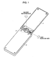
- Fig. 1 is a perspective view of a mobile phone according to an embodiment of the present invention in a vertically opened state.
- the mobile phone according to the present embodiment includes an upper housing 1, a lower housing 2, and a two-axis hinge unit 3.
- the upper housing 1 is provided with a display unit, such as a liquid crystal display and an organic electroluminescence (EL) display.
- the lower housing 2 is provided with an operating unit including a rotation operation key, numeric keys, and the like.
- the two-axis hinge unit 3 allows the housings 1 and 2 to rotate relative to each other around a first rotation axis which extends along short sides of the housings 1 and 2 and also around a second rotation axis which is substantially perpendicular to the first rotation axis and extends along the thickness direction of the housings 1 and 2.
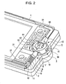
- the two-axis hinge unit 3 includes a first-rotation-axis defining unit 4 which allows the upper housing 1 and the lower housing 2 to rotate relative to each other around the first rotation axis, and a second-rotation-axis defining unit 5 which allows the upper housing 1 and the lower housing 2 to rotate relative to each other around the second rotation axis.
- the first-rotation-axis defining unit 4 is formed by successively fitting a first rotating arm 7, a cam member 8, a spring 9, a second rotating arm 10, a cam member 11, and a washer stopper 12 to a substantially columnar first shaft member 6 shown in Fig. 3 .
- the substantially columnar first shaft member 6 shown in Fig. 3 has a pin-stopping hole 14 at one end thereof. As shown in Figs. 2 and 4 , a pin 15 is inserted into the pin-stopping hole 14 so as to fix the first shaft member 6 to the second-rotation-axis defining unit 5, which will be described below.
- the circumferential outer surface of the first shaft member 6 is cut such that flat surfaces are formed in areas other than a first-rotating-arm receiving portion 16 on which the first rotating arm 7 is disposed and a second-rotating-arm receiving portion 17 on which the second rotating arm 10 is disposed.
- the first rotating arm 7 includes a substantially cylindrical rotation-supporting portion 20 having a hole 19 through which the first shaft member 6 is inserted and a rectangular plate-shaped arm portion 21 provided so as to project from the outer periphery of the rotation-supporting portion 20.
- the first shaft member 6 is inserted through the hole 19 in the first rotating arm 7 such that the first rotating arm 7 is disposed on the first-rotating-arm receiving portion 16 of the first shaft member 6.
- the first-rotating-arm receiving portion 16 of the first shaft member 6 has a circumferential outer surface. Therefore, the first rotating arm 7 is rotatable in the circumferential direction of the first shaft member 6.
- the first rotating arm 7 includes a projection 18 at a first end thereof and a pair of recesses 22a and 22b at a second end thereof.
- the projection 18 at the first end of the first rotating arm 7 engages with a cam portion included in the second-rotation-axis defining unit 5, which will be described below.
- the projection 18 comes into contact with a stopper (denoted by 50 shown in Fig. 10 ) provided in the second-rotation-axis defining unit 5.
- the opening angle is restricted to about 165 degrees.
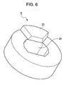
- the recesses 22a and 22b at the second end of the first rotating arm 7 are engageable with a projection 23 provided on the cam member 8 shown in Fig. 6 .
- the cam member 8 has a ring-like cylindrical shape, and a hole 24 is formed in the cam member 8.
- the hole 24 has a shape corresponding to the shape of a portion of the first shaft member 6 at which the circumferential outer surface is cut such that flat surfaces are formed.
- the cam member 8 is fixed to the first shaft member 6 by inserting the first shaft member 6 through the hole 24.
- the recess 22a engages with the projection 23 on the cam member 8 when the mobile phone is closed and the recess 22b engages with the projection 23 on the cam member 8 when the mobile phone is opened by about 165 degrees.
- the cam member 8 is urged against the first rotating arm 7 by the spring 9. Therefore, when the mobile phone is closed, the projection 23 on the cam member 8, which is urged by the spring 9, becomes engaged with the recess 22a in the first rotating arm 7. In addition, when the mobile phone is vertically opened by about 165 degrees, the projection 23 on the cam member 8, which is urged by the spring 9, becomes engaged with the recess 22b in the first rotating arm 7. In either case, a click feeling is generated.
- the second rotating arm 10 includes a substantially cylindrical rotation-supporting portion 26 having a hole 25 through which the first shaft member 6 is inserted and a rectangular plate-shaped arm portion 27 provided so as to project from the outer periphery of the rotation-supporting portion 26.
- the first shaft member 6 is inserted through the hole 25 in the second rotating arm 10 such that the second rotating arm 10 is disposed on the second-rotating-arm receiving portion 17 (see Fig. 3 ) of the first shaft member 6.
- the second-rotating-arm receiving portion 17 of the first shaft member 6 has a circumferential outer surface. Therefore, the second rotating arm 10 is rotatable in the circumferential direction of the first shaft member 6.
- the second rotating arm 10 has a pair of recesses 28a and 28b at an end opposite to the end at which the second rotating arm 10 is in contact with the spring 9.
- the recesses 28a and 28b are engageable with a projection 29 provided on the cam member 11 shown in Fig. 8 .
- the cam member 11 has a ring-like cylindrical shape, and a hole 30 is formed in the cam member 11.
- the hole 30 has a shape corresponding to the shape of a portion of the first shaft member 6 at which the circumferential outer surface is cut such that flat surfaces are formed.
- the cam member 11 is fixed to the first shaft member 6 by inserting the first shaft member 6 through the hole 30.
- the recess 28a engages with the projection 29 on the cam member 11 when the mobile phone is closed and the recess 28b engages with the projection 29 on the cam member 11 when the mobile phone is vertically opened by about 165 degrees.
- the cam member 11 is in contact with the second rotating arm 10 that is urged by the spring 9, as shown in Fig. 2 . Therefore, when the mobile phone is closed, the projection 29 on the cam member 11 becomes engaged with the recess 28a in the second rotating arm 10 which is urged by the spring 9. In addition, when the mobile phone is vertically opened by about 165 degrees, the projection 29 on the cam member 11 becomes engaged with the recess 28b in the second rotating arm 10 which is urged by the spring 9. In either case, a click feeling is generated.
- the washer stopper 12 is fixed to the first shaft member 6 at an end opposite to the end at which the first shaft member 6 is connected to the second-rotation-axis defining unit 5. Therefore, the urging force of the spring 9 is applied in the direction toward the second-rotation-axis defining unit 5 and in the direction toward the washer stopper 12. Thus, the spring 9 urges the cam member 8 against the first rotating arm 7 and the second rotating arm 10 against the cam member 11.
- the arm portion 21 of the first rotating arm 7 and the arm portion 27 of the second rotating arm 10 are fixed to the upper housing 1 by a rectangular plate-shaped fixing plate 31 shown in Figs. 2 and 9 such that the arm portions 21 and 27 are disposed between an upper half and a lower half of the upper housing 1. Therefore, when the mobile phone is vertically opened as shown in Fig. 1 , the first rotating arm 7 and the second rotating arm 10, which are fixed to the upper housing 1, rotate around the first rotation axis defined by the first-rotation-axis defining unit 4 (along the circumferential direction of the first shaft member 6) in response to the operation of opening the mobile phone.
- the second-rotation-axis defining unit 5 includes a rotating-shaft connector 41 which connects the second-rotation-axis defining unit 5 to the above-described first-rotation-axis defining unit 4, a substantially cylindrical second shaft member 42 which is inserted in the rotating-shaft connector 41 and defines the second rotation axis, and a hole-communicating connector 43 fixed to the rotating-shaft connector 41.
- the rotating-shaft connector 41 has a communicating hole 55 which communicates with a hole 44 formed in the second shaft member 42 inserted in the rotating-shaft connector 41.
- the rotating-shaft connector 41 includes a first cylindrical member 45 and a second cylindrical member 46 that are stacked together.
- the second cylindrical member 46 has a larger diameter than the diameter of the first cylindrical member 45.
- the first cylindrical member 45 and the second cylindrical member 46 respectively have holes 47 and 48 which are formed coaxially with each other.
- the diameter of the hole 47 in the first cylindrical member 45 is larger than the diameter of the hole 48 in the second cylindrical member 46.
- the first cylindrical member 45 has a first-shaft-member insertion hole 49 and the stopper 50 at the outer periphery thereof.
- the first shaft member 6 in the first-rotation-axis defining unit 4 is inserted into the first-shaft-member insertion hole 49.
- the stopper 50 restricts the opening angle of the mobile phone to about 165 degrees by coming into contact with the projection 18 on the first rotating arm 7 on the first shaft member 6 when the mobile phone is vertically opened and the opening angle reaches about 165 degrees.
- the first cylindrical member 45 has a pin insertion hole 51 which communicates with the first-shaft-member insertion hole 49 in the top surface thereof.
- the pin 15 is inserted through the pin-stopping hole 14 formed in the first shaft member 6, as shown in Fig. 4 .
- the first shaft member 6 is fixed to the rotating-shaft connector 41.
- the first cylindrical member 45 also has a hole-communicating-connector hole 52 for connecting the hole-communicating connector 43 to the first cylindrical member 45 at the outer periphery thereof.
- the hole-communicating-connector hole 52 is formed at a position substantially opposite to the position at which the first-shaft-member insertion hole 49 is formed.
- the hole-communicating connector 43 is formed such that a cylindrical communicating-hole portion 53 and a connecting piece 54 are connected to each other so that the overall body of the hole-communicating connector 43 has a T-shape.
- the hole-communicating connector 43 has the communicating hole 55 which extends through both the connecting piece 54 and the communicating-hole portion 53.
- a pair of pin insertion holes 56 and 57 are formed in the connecting piece 54 of the communicating connecting member 43.
- the connecting piece 54 of the hole-communicating connector 43 is inserted into the hole-communicating-connector hole 52 in the rotating-shaft connector 41, and pins are inserted into pin insertion holes 59 and 60 formed in the rotating-shaft connector 41. Accordingly, as shown in Fig. 4 , the pins 61 and 62 inserted into the pin insertion holes 59 and 60 are respectively inserted through the pin insertion holes 56 and 57 formed in the connecting piece 54 of the hole-communicating connector 43. Thus, the hole-communicating connector 43 is fixed to the rotating-shaft connector 41.
- Figs. 12 is a perspective view of the rotating-shaft connector 41 viewed from the bottom.
- a hole 65 for receiving the second shaft member 42, a cam member 63, and a spring 64, which are shown in Fig. 4 is formed in the bottom surface of the rotating-shaft connector 41.
- a groove 66 is formed in the bottom surface of the rotating-shaft connector 41 in a spiral shape such that the grove 66 surrounds the hole 65.
- the groove 66 extends around the hole 65 approximately one turn, and wall-shaped stoppers 67 and 68 are provided at the ends of the groove 66.
- the cam member 63 inserted in the hole 65 in the rotating-shaft connector 41 has a ring-like cylindrical shape with a diameter that is slightly smaller than the diameter of the hole 65.
- the cam member 63 has a hole 69 that is cut in a polygonal shape.
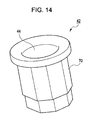
- Fig. 14 is a perspective view of the second shaft member 42. A peripheral portion 70 of the second shaft member 42 is cut into a shape corresponding to the polygonal shape of the hole 69 in the cam member 63. Therefore, when the second shaft member 42 is inserted into the hole 69 in the cam member 63, the cam member 63 is fixed to the second shaft member 42.
- the cam member 63 has four recesses 71 that are arranged in a cross shape.
- the recesses 71 in the cam member 63 are capable of engaging with four projections 72 provided on the rotating-shaft connector 41 shown in Fig. 12 .
- the second shaft member 42 shown in Fig. 14 is inserted into the hole 48 in the second cylindrical member 46 through the hole 47 in the first cylindrical member 45 from above the rotating-shaft connector 41 shown in Fig. 10 .
- the cam member 63 shown in Fig. 13 is inserted into the hole 65 formed in the bottom surface of the rotating-shaft connector 41 shown in Fig. 12 .
- the second shaft member 42 provided on the rotating-shaft connector 41 is inserted through the hole 69 in the cam member 63 and the recesses 71 in the cam member 63 engage with the projections 72 on the rotating-shaft connector 41.
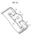
- the spring 64 shown in Fig. 4 is inserted into the hole 65 in the rotating-shaft connector 41, and a fixing plate 75 shown in Fig. 15 is placed on the spring 64 and is fixed to the lower housing 2 with screws 76.
- the second-rotation-axis defining unit 5 is fixed and connected to the lower housing 2.
- the fixing plate 75 has a shaft-member hole 77 in which the second shaft member 42 is inserted and a pair of screw holes 78 used for fixing the fixing plate 75 to the lower housing 2 with the screws.
- the fixing plate 75 also has a sliding-pin hole 80 in which a sliding pin (denoted by 79 in Fig. 15 ) is inserted. The sliding pin 79 slides along the spiral groove 66 formed in the bottom surface of the rotating-shaft connector 41.
- the sliding pin 79 has a bolt shape and includes a substantially circular plate-shaped member 81 and a columnar member 82 which is coaxially connected to the circular plate-shaped member 81 at one flat surface thereof.
- An elliptical plate-shaped member 83 is formed on the columnar member 82 at an intermediate position thereof in the longitudinal direction.
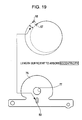
- the groove 66 in the rotating-shaft connector 41 has a spiral shape
- the groove 66 is eccentric, as shown in Fig. 19 . Therefore, when the elliptical plate-shaped member 83 on the sliding pin 79 is caused to slide along the spiral groove 66, it is necessary to move the position of the sliding pin 79 in accordance with the eccentricity of the spiral groove 66. Accordingly, the sliding-pin hole 80 formed in the fixing plate 75 has a length that is large enough to absorb the displacement of the sliding pin 79 caused when the sliding pin 79 slides along the spiral groove 66 (i.e., enough to absorb the above-described eccentricity).
- the housings 1 and 2 can also be smoothly rotated relative to each other around the second rotation axis defined by the second-rotation-axis defining unit 5.
- the hole 55 formed in the hole-communicating connector 43 provided on the rotating-shaft connector 41 communicates with the hole in the second shaft member 42 provided on the rotating-shaft connector 41.
- Fig. 20 is a sectional view of the two-axis hinge unit 3 taken along the longitudinal direction of the mobile phone.
- a harness 90 (or a flexible board) is disposed so as to extend through the hole in the second shaft member 42 provided on the rotating-shaft connector 41 and the hole 55 in the hole-communicating connector 43 provided on the rotating-shaft connector 41.
- the electrical components such as the display unit, provided in the upper housing 1 are connected to the electrical components, such as the control unit and the operating unit, provided in the lower housing 2.
- the space for accommodating an electrical connecting member, such as a harness or a flexible board can be eliminated from the two-axis hinge unit 3 and the size of the two-axis hinge unit 3 can be reduced.
- a user may, for example, hold the upper housing 1 with the right hand and the lower housing 2 with the left hand, and apply a force to the upper housing 1 by pushing the upper housing 1 upward with the right hand.
- the arm portion 21 of the first rotating arm 7 provided on the first shaft member 6 and the arm portion 27 of the second rotating arm 10 provided on the first shaft member 6 are placed between the fixing plate 31 and the upper housing 1. Therefore, when the force is applied as described above, the housings 1 and 2 are rotated relative to each other around the first rotation axis (along the circumferential direction of the first shaft member 6) and the mobile phone is set to the vertically opened state shown in Fig. 1 .
- the projection 18 on the first rotating arm 7 shown in Fig. 5 is in contact with the stopper 50 on the rotating-shaft connector 41 shown in Fig. 10 .
- the projection 18 on the first rotating arm 7 is temporarily separated from the stopper 50 on the rotating-shaft connector 41.
- the opening angle between the housings 1 and 2 reaches, for example, about 165 degrees
- the projection 18 on the first rotating arm 7 comes into contact with the stopper 50 on the rotating-shaft connector 41 again.
- the opening angle between the housings 1 and 2 is restricted to about 165 degrees and the mobile phone is prevented from breaking when the user applies a large force to open the mobile phone.
- the projection 29 on the cam member 11 shown in Fig. 8 is engaged with the recess 28a in the second rotating arm 10 shown in Fig. 7 .
- the projection 29 on the cam member 11 is released from the recess 28a in the second rotating arm 10. Then, when the opening angle between the housings 1 and 2 reaches, for example, about 165 degrees, the projection 29 on the cam member 11 engages with the recess 28b in the second rotating arm 10.
- the second rotating arm 10 is urged against the cam member 11 by the spring 9. Therefore, when the opening angle between the housings 1 and 2 reaches, for example, about 165 degrees and the projection 29 on the cam member 11 engages with the recess 28b in the second rotating arm 10, a clicking sound is generated. The user hears the clicking sound and recognizes that the mobile phone is set to the vertically opened state.
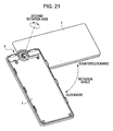
- the clockwise or counterclockwise force is transmitted to the first shaft member 6 through the arm portion 21 of the first rotating arm 7 and the arm portion 27 of the second rotating arm 10, which are fixed to the upper housing 1 as shown in Fig. 2 .
- the rotating-shaft connector 41 is rotated clockwise or counterclockwise with the first shaft member 6 serving as the power point.
- the upper housing 1 rotates clockwise or counterclockwise with the second shaft member 42 serving as the rotating shaft.
- the sliding pin 79 When the mobile phone is in the closed state, the sliding pin 79 is positioned approximately at the midpoint of the spiral groove 66 formed in the bottom surface of the rotating-shaft connector 41, as shown in Fig. 18 . If the user rotates the upper housing 1 clockwise from this state, the sliding pin 79 comes into contact with the stopper 67 at one end of the spiral groove 66 when the rotation angle between the upper housing 1 and the lower housing 2 reaches, for example, about 180 degrees, in other words, when the upper housing 1 and the lower housing 2 are set to the vertically opened state shown in Fig. 1 . Thus, the rotation angle of the clockwise rotation is restricted to about 180 degrees.
- the sliding pin 79 comes into contact with the stopper 68 at the other end of the spiral groove 66 when the rotation angle between the upper housing 1 and the lower housing 2 reaches, for example, about 180 degrees, in other words, when the upper housing 1 and the lower housing 2 are set to the vertically opened state shown in Fig. 1 .
- the rotation angle of the counterclockwise rotation is also restricted to about 180 degrees.
- the sliding-pin hole 80 formed in the fixing plate 75 with which the sliding pin 79 is fixed has a length that is large enough to absorb the displacement of the sliding pin 79 caused when the sliding pin 79 slides along the groove 66. Therefore, as described above, when the upper housing 1 is rotated clockwise or counterclockwise, the sliding pin 79 smoothly slides along the groove 66 and the upper housing 1 can be smoothly rotated.
- the housings 1 and 2 can be rotated relative to each other around the second rotation axis.
- the user can stop the rotation around the second rotation axis at a desired rotation angle and watch, for example, television, characters or images (still images or moving images) displayed on the display unit, or the like.
- the upper housing 1 is rotated clockwise or counterclockwise from the state in which the mobile phone is closed and the upper housing 1 and the lower housing 2 are stacked on top of each other.
- the mobile phone can also be closed by rotating the upper housing 1 clockwise or counterclockwise from the state in which the mobile phone is vertically opened as shown in Fig. 1 .
- the closed state of the mobile phone is a state in which the display unit provided in the upper housing 1 and the operating unit provided in the lower housing 2 face each other, as shown in Fig. 22 .
- the mobile phone of the present embodiment can also be closed such that the display unit provided in the upper housing 1 and the operating unit provided in the lower housing 2 face the same direction.
- the mobile phone is vertically opened from the closed state in which the display unit provided in the upper housing 1 and the operating unit provided in the lower housing 2 face each other, so that the mobile phone is set to the vertically opened state shown in Fig. 1 .
- the upper housing 1 is rotated clockwise or counterclockwise from the state in which the mobile phone is vertically opened. Accordingly, the upper housing 1 is rotated around the second rotation axis as shown in Fig. 23 , and the mobile phone is closed such that a display unit 95 faces outward, as shown in Fig. 24 . In other words, the mobile phone is closed such that the display unit 95 and the operating unit provided in the lower housing 2 face the same direction.
- the user can watch, for example, television, characters or images (still images or moving images) displayed on the display unit, etc., while the display unit 95 faces outward and the mobile phone is closed and folded into a compact size.
- the harness 90 (or a flexible board) is disposed so as to extend through the hole in the second shaft member 42 provided on the rotating-shaft connector 41 of the two-axis hinge unit 3 and the hole 55 in the hole-communicating connector 43 provided on the rotating-shaft connector 41.
- the electrical components such as the display unit, provided in the upper housing 1 are connected to the electrical components, such as the control unit and the operating unit, provided in the lower housing 2.
- the space for accommodating the electrical connecting member, such as a harness or a flexible board can be eliminated from the two-axis hinge unit 3 and the size of the two-axis hinge unit 3 can be reduced.
- the size of the two-axis hinge unit 3 can be reduced, the occurrence of electric wave disturbances which occur due to the hinge unit if the hinge unit largely projects from the housing can be prevented.
- the present invention is applied to a mobile phone.
- the present invention may also be applied to other types of apparatuses, such as a personal handyphone system (PHS), a personal digital assistant (PDA), a portable game device, a digital camera, and a notebook personal computer.
- PHS personal handyphone system
- PDA personal digital assistant
- portable game device e.g., a portable game player
- digital camera e.g., a digital camera
- notebook personal computer e.g., a notebook personal computer.
Description
- The present invention relates to a two-axis hinge device suitable for use in a mobile phone, a personal handyphone system (PHS), a personal digital assistant (PDA), a portable game device, a notebook personal computer, etc., which includes a first housing and a second housing that are connected to each other with a hinge unit, and to a mobile terminal apparatus.
- More particularly, the present invention relates to a two-axis hinge device which includes a first-rotation-axis defining unit and a second-rotation-axis defining unit that are perpendicular to each other, in which at least the second-rotation-axis defining unit has a substantially cylindrical shape, and in which a substantially cylindrical hole-communicating connector having a hole which communicates with a hole in the second-rotation-axis defining unit is provided on the second-rotation-axis defining unit is provided with. The overall size of the two-axis hinge device can be reduced since an electrical connecting member, such as a harness or a flexible board, for connecting electrical components disposed in a first housing and a second housing to each other can be disposed so as to extend through the hole in the second-rotation-axis defining unit and the hole in the hole-communicating connector. The present invention also relates to a mobile terminal apparatus including the two-axis hinge device.
- Japanese Unexamined Patent Application Publication No.
2007-281239 pages Fig. 1 ) discloses a compact foldable mobile terminal in which the resistance to twisting and bending of a flexible printed circuit (FPC) board is increased. This foldable mobile terminal includes a two-axis hinge mechanism in which a first hinge shaft and a second hinge shaft are connected to each other with a connecting member such that the first and second hinge shafts are perpendicular to each other. - The two-axis hinge mechanism includes an FPC holding structure for holding an FPC including a short section and a long section. The short section is disposed parallel to the second hinge shaft, and the long section is inclined with respect to the short section and is wound around the second hinge shaft. The short section of the FPC is held on the connecting member by a holding member formed of an elastic body that is partially cut in an area near a base end of the wound portion of the long section of the FPC.
- In the two-axis hinge mechanism of the above-described foldable mobile terminal, the FPC is held by the holding member formed of the elastic body that is partially cut in an area near the base end of the wound portion. Therefore, the distance between a base end of the FPC at which the FPC is held and the base end of the wound portion of the FPC can be increased without increasing the length of the short section of the FPC. Accordingly, the load applied at the base end of the FPC when the FPC is twisted can be reduced and the resistance to twisting of the FPC can be increased.
- In addition, since the holding member is formed of the elastic body, when a load is applied to the FPC, the holding member contracts and thereby suppresses the FPC from being suddenly deformed. In other words, the bending radius at which the FPC is twisted is increased. Thus, the resistance can be increased. In addition, since the short section of the FPC is twisted, the load applied to the long section of the FPC due to the winding of the long section can be reduced. Thus, the load applied to the long section due to the winding thereof can be reduced without increasing the winding radius.
- However, in the two-axis hinge mechanism of the foldable mobile terminal disclosed in Japanese Unexamined Patent Application Publication No.
2007-281239 - If the size of the hinge device is large, the hinge device largely protrudes from a housing. Therefore, there is a risk that electric wave disturbances will occur due to the hinge device.
- In light of the above-described problems, it is desirable to provide a two-axis hinge device in which a space for installing a harness or a flexible board for connecting electrical components disposed in first and second housings to each other can be omitted, so that the size of the two-axis hinge device can be reduced by an amount corresponding to the size of the space and the occurrence of electric wave disturbances or the like which occur if the size of the two-axis hinge device is large can be prevented. It is also desirable to provide a mobile terminal apparatus including the two-axis hinge device.
- The invention is directed to a two-axis hinge device, as defined in
claim 1. - A two-axis hinge device according to an embodiment of the present invention includes a first-rotation-axis defining unit which defines a first rotation axis; a rotating arm fixed to a first housing, the rotating arm being provided on the first-rotation-axis defining unit such that the rotating arm is rotatable around the first rotation axis; a second-rotation-axis defining unit fixed to a second housing, the second-rotation-axis defining unit having a substantially cylindrical shape and defining a second rotation axis which is substantially perpendicular to the first rotation axis, the first-rotation-axis defining unit being fixed to and supported by the second-rotation-axis defining unit; and a hole-communicating connector fixed to the second-rotation-axis defining unit, the hole-communicating connector having a substantially cylindrical shape and being provided with a hole which communicates with a hole in the second-rotation-axis defining unit.
- The two-axis hinge device includes the first-rotation-axis defining unit and the second-rotation-axis defining unit that are perpendicular to each other. At least the second-rotation-axis defining unit has a substantially cylindrical shape, and the substantially cylindrical hole-communicating connector having the hole which communicates with the hole in the second-rotation-axis defining unit is provided on the second-rotation-axis defining unit.
- Thus, the overall size of the two-axis hinge device can be reduced since an electrical connecting member, such as a harness or a flexible board, for connecting electrical components disposed in the first housing and the second housing to each other can be disposed so as to extend through the hole in the second-rotation-axis defining unit and the hole in the hole-communicating connector. In addition, since the overall size can be reduced, the occurrence of electric wave disturbances or the like which occur if the size of the two-axis hinge device is large can be prevented.
- According to the present invention, the size of the two-axis hinge device can be reduced. In addition, since the size of the two-axis hinge device can be reduced, the occurrence of electric wave disturbances or the like which occur if the size of the two-axis hinge unit is large can be prevented. Reference is also made to documents
US 2005/0245294 ,US 2005/0034450 andEP 1 467 539 -
-
Fig. 1 is a perspective view of a mobile phone according to an embodiment of the present invention in a vertically opened state; -
Fig. 2 is a perspective view of a two-axis hinge unit included in the mobile phone; -
Fig. 3 is a perspective view of a first shaft member included in the two-axis hinge unit; -
Fig. 4 is a perspective view of the main part of the two-axis hinge unit; -
Fig. 5 is a perspective view of a first rotating arm included in the first shaft member of the two-axis hinge unit; -
Fig. 6 is a perspective view of a cam member fitted to the first rotating arm; -
Fig. 7 is a perspective view of a second rotating arm included in the first shaft member of the two-axis hinge unit; -
Fig. 8 is a perspective view of a cam member fitted to the second rotating arm; -
Fig. 9 is a perspective view of a fixing plate for fixing the first and second rotating arms of the two-axis hinge unit to an upper housing; -
Fig. 10 is a perspective view of a rotating-shaft connector for connecting the first and second shaft members of the two-axis hinge unit to each other; -
Fig. 11 is a perspective view of a hole-communicating connector which is connected to the rotating-shaft connector; -
Fig. 12 is a perspective view of the rotating-shaft connector viewed from the bottom; -
Fig. 13 is a perspective view of a cam member provided on the rotating-shaft connector; -
Fig. 14 is a perspective view of the second shaft member inserted in the rotating-shaft connector; -
Fig. 15 is a perspective view illustrating the state in which the two-axis hinge unit is fixed to a lower housing with a fixing plate; -
Fig. 16 is a perspective view of the fixing plate; -
Fig. 17 is a perspective view of a sliding pin which slides along a spiral groove formed in a bottom surface of the rotating-shaft connector; -
Fig. 18 is a perspective view showing the position of the sliding pin in the spiral groove in the state in which the mobile phone is closed; -
Fig. 19 is a diagram illustrating the relationship between the eccentricity of the spiral groove in the bottom surface of the rotating-shaft connector and a sliding-pin hole formed in the fixing plate; -
Fig. 20 is a sectional view of the two-axis hinge unit, illustrating the state in which a harness is disposed in the two-axis hinge unit; -
Fig. 21 is a perspective view illustrating a rotating operation of the two-axis hinge unit around a second rotation axis; -
Fig. 22 is a perspective view of the mobile phone according to the embodiment in the closed state; -
Fig. 23 is a perspective view illustrating a rotating operation around the second rotation axis performed from the state in which the mobile phone according to the embodiment is vertically opened; and -
Fig. 24 is a perspective view of the mobile phone of the embodiment in a closed state in which a display unit faces outward, which is obtained as a result of the rotating operation around the second rotation axis from the vertically opened state. - The present invention can be applied to a foldable mobile terminal apparatus. Structure of Mobile Phone
-
Fig. 1 is a perspective view of a mobile phone according to an embodiment of the present invention in a vertically opened state. As shown inFig. 1 , the mobile phone according to the present embodiment includes anupper housing 1, alower housing 2, and a two-axis hinge unit 3. Theupper housing 1 is provided with a display unit, such as a liquid crystal display and an organic electroluminescence (EL) display. Thelower housing 2 is provided with an operating unit including a rotation operation key, numeric keys, and the like. The two-axis hinge unit 3 allows thehousings housings housings - As shown in
Fig. 2 , the two-axis hinge unit 3 includes a first-rotation-axis defining unit 4 which allows theupper housing 1 and thelower housing 2 to rotate relative to each other around the first rotation axis, and a second-rotation-axis defining unit 5 which allows theupper housing 1 and thelower housing 2 to rotate relative to each other around the second rotation axis. - Referring to
Fig. 2 , the first-rotation-axis defining unit 4 is formed by successively fitting a firstrotating arm 7, acam member 8, aspring 9, a secondrotating arm 10, acam member 11, and awasher stopper 12 to a substantially columnarfirst shaft member 6 shown inFig. 3 . - The substantially columnar
first shaft member 6 shown inFig. 3 has a pin-stoppinghole 14 at one end thereof. As shown inFigs. 2 and4 , apin 15 is inserted into the pin-stoppinghole 14 so as to fix thefirst shaft member 6 to the second-rotation-axis defining unit 5, which will be described below. - As shown in
Fig. 3 , the circumferential outer surface of thefirst shaft member 6 is cut such that flat surfaces are formed in areas other than a first-rotating-arm receiving portion 16 on which the firstrotating arm 7 is disposed and a second-rotating-arm receiving portion 17 on which the secondrotating arm 10 is disposed. - As shown in
Fig. 5 , the firstrotating arm 7 includes a substantially cylindrical rotation-supportingportion 20 having ahole 19 through which thefirst shaft member 6 is inserted and a rectangular plate-shapedarm portion 21 provided so as to project from the outer periphery of the rotation-supportingportion 20. Thefirst shaft member 6 is inserted through thehole 19 in the firstrotating arm 7 such that the firstrotating arm 7 is disposed on the first-rotating-arm receiving portion 16 of thefirst shaft member 6. As described above, the first-rotating-arm receiving portion 16 of thefirst shaft member 6 has a circumferential outer surface. Therefore, the firstrotating arm 7 is rotatable in the circumferential direction of thefirst shaft member 6. - Referring to
Fig. 5 , the firstrotating arm 7 includes aprojection 18 at a first end thereof and a pair ofrecesses projection 18 at the first end of the firstrotating arm 7 engages with a cam portion included in the second-rotation-axis defining unit 5, which will be described below. When the mobile phone is vertically opened and an opening angle between theupper housing 1 and thelower housing 2 reaches about 165 degrees, theprojection 18 comes into contact with a stopper (denoted by 50 shown inFig. 10 ) provided in the second-rotation-axis defining unit 5. Thus, the opening angle is restricted to about 165 degrees. - The
recesses rotating arm 7 are engageable with aprojection 23 provided on thecam member 8 shown inFig. 6 . Thecam member 8 has a ring-like cylindrical shape, and ahole 24 is formed in thecam member 8. Thehole 24 has a shape corresponding to the shape of a portion of thefirst shaft member 6 at which the circumferential outer surface is cut such that flat surfaces are formed. Thecam member 8 is fixed to thefirst shaft member 6 by inserting thefirst shaft member 6 through thehole 24. Of therecesses rotating arm 7, therecess 22a engages with theprojection 23 on thecam member 8 when the mobile phone is closed and therecess 22b engages with theprojection 23 on thecam member 8 when the mobile phone is opened by about 165 degrees. - As shown in
Fig. 2 , thecam member 8 is urged against the firstrotating arm 7 by thespring 9. Therefore, when the mobile phone is closed, theprojection 23 on thecam member 8, which is urged by thespring 9, becomes engaged with therecess 22a in the firstrotating arm 7. In addition, when the mobile phone is vertically opened by about 165 degrees, theprojection 23 on thecam member 8, which is urged by thespring 9, becomes engaged with therecess 22b in the firstrotating arm 7. In either case, a click feeling is generated. - As shown in
Fig. 7 , the secondrotating arm 10 includes a substantially cylindrical rotation-supportingportion 26 having ahole 25 through which thefirst shaft member 6 is inserted and a rectangular plate-shapedarm portion 27 provided so as to project from the outer periphery of the rotation-supportingportion 26. Thefirst shaft member 6 is inserted through thehole 25 in the secondrotating arm 10 such that the secondrotating arm 10 is disposed on the second-rotating-arm receiving portion 17 (seeFig. 3 ) of thefirst shaft member 6. As described above, the second-rotating-arm receiving portion 17 of thefirst shaft member 6 has a circumferential outer surface. Therefore, the secondrotating arm 10 is rotatable in the circumferential direction of thefirst shaft member 6. - The second
rotating arm 10 has a pair ofrecesses rotating arm 10 is in contact with thespring 9. Therecesses projection 29 provided on thecam member 11 shown inFig. 8 . Thecam member 11 has a ring-like cylindrical shape, and ahole 30 is formed in thecam member 11. Thehole 30 has a shape corresponding to the shape of a portion of thefirst shaft member 6 at which the circumferential outer surface is cut such that flat surfaces are formed. Thecam member 11 is fixed to thefirst shaft member 6 by inserting thefirst shaft member 6 through thehole 30. Of therecesses rotating arm 10 opposite to the end at which thespring 9 is provided, therecess 28a engages with theprojection 29 on thecam member 11 when the mobile phone is closed and therecess 28b engages with theprojection 29 on thecam member 11 when the mobile phone is vertically opened by about 165 degrees. - The
cam member 11 is in contact with the secondrotating arm 10 that is urged by thespring 9, as shown inFig. 2 . Therefore, when the mobile phone is closed, theprojection 29 on thecam member 11 becomes engaged with therecess 28a in the secondrotating arm 10 which is urged by thespring 9. In addition, when the mobile phone is vertically opened by about 165 degrees, theprojection 29 on thecam member 11 becomes engaged with therecess 28b in the secondrotating arm 10 which is urged by thespring 9. In either case, a click feeling is generated. - As shown in
Fig. 2 , thewasher stopper 12 is fixed to thefirst shaft member 6 at an end opposite to the end at which thefirst shaft member 6 is connected to the second-rotation-axis defining unit 5. Therefore, the urging force of thespring 9 is applied in the direction toward the second-rotation-axis defining unit 5 and in the direction toward thewasher stopper 12. Thus, thespring 9 urges thecam member 8 against the firstrotating arm 7 and the secondrotating arm 10 against thecam member 11. - The
arm portion 21 of the firstrotating arm 7 and thearm portion 27 of the secondrotating arm 10 are fixed to theupper housing 1 by a rectangular plate-shapedfixing plate 31 shown inFigs. 2 and9 such that thearm portions upper housing 1. Therefore, when the mobile phone is vertically opened as shown inFig. 1 , the firstrotating arm 7 and the secondrotating arm 10, which are fixed to theupper housing 1, rotate around the first rotation axis defined by the first-rotation-axis defining unit 4 (along the circumferential direction of the first shaft member 6) in response to the operation of opening the mobile phone. - Referring to
Fig. 2 , the second-rotation-axis defining unit 5 includes a rotating-shaft connector 41 which connects the second-rotation-axis defining unit 5 to the above-described first-rotation-axis defining unit 4, a substantially cylindricalsecond shaft member 42 which is inserted in the rotating-shaft connector 41 and defines the second rotation axis, and a hole-communicatingconnector 43 fixed to the rotating-shaft connector 41. The rotating-shaft connector 41 has a communicatinghole 55 which communicates with ahole 44 formed in thesecond shaft member 42 inserted in the rotating-shaft connector 41. - The rotating-
shaft connector 41 includes a firstcylindrical member 45 and a secondcylindrical member 46 that are stacked together. The secondcylindrical member 46 has a larger diameter than the diameter of the firstcylindrical member 45. The firstcylindrical member 45 and the secondcylindrical member 46 respectively haveholes hole 47 in the firstcylindrical member 45 is larger than the diameter of thehole 48 in the secondcylindrical member 46. - The first
cylindrical member 45 has a first-shaft-member insertion hole 49 and thestopper 50 at the outer periphery thereof. Thefirst shaft member 6 in the first-rotation-axis defining unit 4 is inserted into the first-shaft-member insertion hole 49. Thestopper 50 restricts the opening angle of the mobile phone to about 165 degrees by coming into contact with theprojection 18 on the firstrotating arm 7 on thefirst shaft member 6 when the mobile phone is vertically opened and the opening angle reaches about 165 degrees. - The first
cylindrical member 45 has apin insertion hole 51 which communicates with the first-shaft-member insertion hole 49 in the top surface thereof. When thepin 15 is into thepin insertion hole 51 while thefirst shaft member 6 is inserted in the first-shaft-member insertion hole 49, thepin 15 is inserted through the pin-stoppinghole 14 formed in thefirst shaft member 6, as shown inFig. 4 . Thus, thefirst shaft member 6 is fixed to the rotating-shaft connector 41. - In addition, the first
cylindrical member 45 also has a hole-communicating-connector hole 52 for connecting the hole-communicatingconnector 43 to the firstcylindrical member 45 at the outer periphery thereof. The hole-communicating-connector hole 52 is formed at a position substantially opposite to the position at which the first-shaft-member insertion hole 49 is formed. As shown inFig. 11 , the hole-communicatingconnector 43 is formed such that a cylindrical communicating-hole portion 53 and a connectingpiece 54 are connected to each other so that the overall body of the hole-communicatingconnector 43 has a T-shape. The hole-communicatingconnector 43 has the communicatinghole 55 which extends through both the connectingpiece 54 and the communicating-hole portion 53. In addition, a pair of pin insertion holes 56 and 57 are formed in the connectingpiece 54 of the communicating connectingmember 43. - The connecting
piece 54 of the hole-communicatingconnector 43 is inserted into the hole-communicating-connector hole 52 in the rotating-shaft connector 41, and pins are inserted into pin insertion holes 59 and 60 formed in the rotating-shaft connector 41. Accordingly, as shown inFig. 4 , thepins piece 54 of the hole-communicatingconnector 43. Thus, the hole-communicatingconnector 43 is fixed to the rotating-shaft connector 41. -
Figs. 12 is a perspective view of the rotating-shaft connector 41 viewed from the bottom. As shown inFig. 12 , ahole 65 for receiving thesecond shaft member 42, acam member 63, and aspring 64, which are shown inFig. 4 , is formed in the bottom surface of the rotating-shaft connector 41. In addition, agroove 66 is formed in the bottom surface of the rotating-shaft connector 41 in a spiral shape such that thegrove 66 surrounds thehole 65. Thegroove 66 extends around thehole 65 approximately one turn, and wall-shapedstoppers groove 66. - Referring to
Fig. 13 , thecam member 63 inserted in thehole 65 in the rotating-shaft connector 41 has a ring-like cylindrical shape with a diameter that is slightly smaller than the diameter of thehole 65. Thecam member 63 has ahole 69 that is cut in a polygonal shape.Fig. 14 is a perspective view of thesecond shaft member 42. Aperipheral portion 70 of thesecond shaft member 42 is cut into a shape corresponding to the polygonal shape of thehole 69 in thecam member 63. Therefore, when thesecond shaft member 42 is inserted into thehole 69 in thecam member 63, thecam member 63 is fixed to thesecond shaft member 42. - In addition, as shown in
Fig. 13 , thecam member 63 has fourrecesses 71 that are arranged in a cross shape. Therecesses 71 in thecam member 63 are capable of engaging with fourprojections 72 provided on the rotating-shaft connector 41 shown inFig. 12 . - In the process of connecting the second-rotation-
axis defining unit 5 to the housing, first, thesecond shaft member 42 shown inFig. 14 is inserted into thehole 48 in the secondcylindrical member 46 through thehole 47 in the firstcylindrical member 45 from above the rotating-shaft connector 41 shown inFig. 10 . Then, in this state, thecam member 63 shown inFig. 13 is inserted into thehole 65 formed in the bottom surface of the rotating-shaft connector 41 shown inFig. 12 . Thus, thesecond shaft member 42 provided on the rotating-shaft connector 41 is inserted through thehole 69 in thecam member 63 and therecesses 71 in thecam member 63 engage with theprojections 72 on the rotating-shaft connector 41. - In this state, the
spring 64 shown inFig. 4 is inserted into thehole 65 in the rotating-shaft connector 41, and a fixingplate 75 shown inFig. 15 is placed on thespring 64 and is fixed to thelower housing 2 withscrews 76. Thus, the second-rotation-axis defining unit 5 is fixed and connected to thelower housing 2. - Referring to
Fig. 16 , the fixingplate 75 has a shaft-member hole 77 in which thesecond shaft member 42 is inserted and a pair of screw holes 78 used for fixing the fixingplate 75 to thelower housing 2 with the screws. In addition, the fixingplate 75 also has a sliding-pin hole 80 in which a sliding pin (denoted by 79 inFig. 15 ) is inserted. The slidingpin 79 slides along thespiral groove 66 formed in the bottom surface of the rotating-shaft connector 41. - As shown in
Fig. 17 , the slidingpin 79 has a bolt shape and includes a substantially circular plate-shapedmember 81 and acolumnar member 82 which is coaxially connected to the circular plate-shapedmember 81 at one flat surface thereof. An elliptical plate-shapedmember 83 is formed on thecolumnar member 82 at an intermediate position thereof in the longitudinal direction. In the state in which the slidingpin 79 is disposed so as to extend into the rotating-shaft connector 41 through the fixingplate 75 as shown inFig. 15 , the elliptical plate-shapedmember 83 on the slidingpin 79 slides along thespiral groove 66 in the rotating-shaft connector 41, as shown inFig. 18 . - Since the
groove 66 in the rotating-shaft connector 41 has a spiral shape, thegroove 66 is eccentric, as shown inFig. 19 . Therefore, when the elliptical plate-shapedmember 83 on the slidingpin 79 is caused to slide along thespiral groove 66, it is necessary to move the position of the slidingpin 79 in accordance with the eccentricity of thespiral groove 66. Accordingly, the sliding-pin hole 80 formed in the fixingplate 75 has a length that is large enough to absorb the displacement of the slidingpin 79 caused when the slidingpin 79 slides along the spiral groove 66 (i.e., enough to absorb the above-described eccentricity). Thus, thehousings axis defining unit 5. - In the two-
axis hinge unit 3, as shown inFig. 2 , thehole 55 formed in the hole-communicatingconnector 43 provided on the rotating-shaft connector 41 communicates with the hole in thesecond shaft member 42 provided on the rotating-shaft connector 41. -
Fig. 20 is a sectional view of the two-axis hinge unit 3 taken along the longitudinal direction of the mobile phone. As is clear fromFig. 20 , in the mobile phone, a harness 90 (or a flexible board) is disposed so as to extend through the hole in thesecond shaft member 42 provided on the rotating-shaft connector 41 and thehole 55 in the hole-communicatingconnector 43 provided on the rotating-shaft connector 41. In this manner, the electrical components, such as the display unit, provided in theupper housing 1 are connected to the electrical components, such as the control unit and the operating unit, provided in thelower housing 2. Thus, the space for accommodating an electrical connecting member, such as a harness or a flexible board, can be eliminated from the two-axis hinge unit 3 and the size of the two-axis hinge unit 3 can be reduced. - An operation of opening and closing the mobile phone according to the present embodiment including the above-described two-
axis hinge unit 3 will now be described. - The operation of the two-
axis hinge unit 3 in the process of opening the mobile phone in the closed state, in which theupper housing 1 and thelower housing 2 are stacked on top of each other, to the vertically opened state shown inFig. 1 will be described. In this case, a user may, for example, hold theupper housing 1 with the right hand and thelower housing 2 with the left hand, and apply a force to theupper housing 1 by pushing theupper housing 1 upward with the right hand. - As described above with reference to
Fig. 2 , thearm portion 21 of the firstrotating arm 7 provided on thefirst shaft member 6 and thearm portion 27 of the secondrotating arm 10 provided on thefirst shaft member 6 are placed between the fixingplate 31 and theupper housing 1. Therefore, when the force is applied as described above, thehousings Fig. 1 . - When the mobile phone is in the closed state, the
projection 18 on the firstrotating arm 7 shown inFig. 5 is in contact with thestopper 50 on the rotating-shaft connector 41 shown inFig. 10 . When the user vertically opens the mobile phone and thehousings projection 18 on the firstrotating arm 7 is temporarily separated from thestopper 50 on the rotating-shaft connector 41. Then, when the opening angle between thehousings projection 18 on the firstrotating arm 7 comes into contact with thestopper 50 on the rotating-shaft connector 41 again. Thus, the opening angle between thehousings - In addition, when the mobile phone is in the closed state, the
projection 29 on thecam member 11 shown inFig. 8 is engaged with therecess 28a in the secondrotating arm 10 shown inFig. 7 . When the user vertically opens the mobile phone and thehousings projection 29 on thecam member 11 is released from therecess 28a in the secondrotating arm 10. Then, when the opening angle between thehousings projection 29 on thecam member 11 engages with therecess 28b in the secondrotating arm 10. - As described above, the second
rotating arm 10 is urged against thecam member 11 by thespring 9. Therefore, when the opening angle between thehousings projection 29 on thecam member 11 engages with therecess 28b in the secondrotating arm 10, a clicking sound is generated. The user hears the clicking sound and recognizes that the mobile phone is set to the vertically opened state. - When the mobile phone in the vertically opened state is closed by rotating the
housings projection 29 on thecam member 11, which is engaged with therecess 28b in the secondrotating arm 10 in the vertically opened state, is released from therecess 28b in the secondrotating arm 10. Then, when the mobile phone is set to the closed state, theprojection 29 on thecam member 11 engages with therecess 28a in the secondrotating arm 10. Also in this case, the clicking sound is generated and the user recognizes that the mobile phone is closed when the user hears the clicking sound. - If a clockwise or counterclockwise force is applied to the
upper housing 1 while the mobile phone is in the closed state in which theupper housing 1 and thelower housing 2 are stacked on top of each other, the clockwise or counterclockwise force is transmitted to thefirst shaft member 6 through thearm portion 21 of the firstrotating arm 7 and thearm portion 27 of the secondrotating arm 10, which are fixed to theupper housing 1 as shown inFig. 2 . Thus, the rotating-shaft connector 41 is rotated clockwise or counterclockwise with thefirst shaft member 6 serving as the power point. Accordingly, as shown inFig. 21 , theupper housing 1 rotates clockwise or counterclockwise with thesecond shaft member 42 serving as the rotating shaft. - When the mobile phone is in the closed state, the sliding
pin 79 is positioned approximately at the midpoint of thespiral groove 66 formed in the bottom surface of the rotating-shaft connector 41, as shown inFig. 18 . If the user rotates theupper housing 1 clockwise from this state, the slidingpin 79 comes into contact with thestopper 67 at one end of thespiral groove 66 when the rotation angle between theupper housing 1 and thelower housing 2 reaches, for example, about 180 degrees, in other words, when theupper housing 1 and thelower housing 2 are set to the vertically opened state shown inFig. 1 . Thus, the rotation angle of the clockwise rotation is restricted to about 180 degrees. - Similarly, if the user rotates the
upper housing 1 counterclockwise from the state in which the mobile phone is closed, the slidingpin 79 comes into contact with thestopper 68 at the other end of thespiral groove 66 when the rotation angle between theupper housing 1 and thelower housing 2 reaches, for example, about 180 degrees, in other words, when theupper housing 1 and thelower housing 2 are set to the vertically opened state shown inFig. 1 . Thus, the rotation angle of the counterclockwise rotation is also restricted to about 180 degrees. - The sliding-
pin hole 80 formed in the fixingplate 75 with which the slidingpin 79 is fixed has a length that is large enough to absorb the displacement of the slidingpin 79 caused when the slidingpin 79 slides along thegroove 66. Therefore, as described above, when theupper housing 1 is rotated clockwise or counterclockwise, the slidingpin 79 smoothly slides along thegroove 66 and theupper housing 1 can be smoothly rotated. - In the mobile phone according to the present embodiment, the
housings - In the above description, the
upper housing 1 is rotated clockwise or counterclockwise from the state in which the mobile phone is closed and theupper housing 1 and thelower housing 2 are stacked on top of each other. However, the mobile phone can also be closed by rotating theupper housing 1 clockwise or counterclockwise from the state in which the mobile phone is vertically opened as shown inFig. 1 . - In general, the closed state of the mobile phone is a state in which the display unit provided in the
upper housing 1 and the operating unit provided in thelower housing 2 face each other, as shown inFig. 22 . However, according the mobile phone of the present embodiment, the mobile phone can also be closed such that the display unit provided in theupper housing 1 and the operating unit provided in thelower housing 2 face the same direction. - In this case, first, the mobile phone is vertically opened from the closed state in which the display unit provided in the
upper housing 1 and the operating unit provided in thelower housing 2 face each other, so that the mobile phone is set to the vertically opened state shown inFig. 1 . - Then, the
upper housing 1 is rotated clockwise or counterclockwise from the state in which the mobile phone is vertically opened. Accordingly, theupper housing 1 is rotated around the second rotation axis as shown inFig. 23 , and the mobile phone is closed such that adisplay unit 95 faces outward, as shown inFig. 24 . In other words, the mobile phone is closed such that thedisplay unit 95 and the operating unit provided in thelower housing 2 face the same direction. - Accordingly, the user can watch, for example, television, characters or images (still images or moving images) displayed on the display unit, etc., while the
display unit 95 faces outward and the mobile phone is closed and folded into a compact size. - As is clear from the above description, in the mobile phone according to the present embodiment, the harness 90 (or a flexible board) is disposed so as to extend through the hole in the
second shaft member 42 provided on the rotating-shaft connector 41 of the two-axis hinge unit 3 and thehole 55 in the hole-communicatingconnector 43 provided on the rotating-shaft connector 41. In this manner, the electrical components, such as the display unit, provided in theupper housing 1 are connected to the electrical components, such as the control unit and the operating unit, provided in thelower housing 2. Thus, the space for accommodating the electrical connecting member, such as a harness or a flexible board, can be eliminated from the two-axis hinge unit 3 and the size of the two-axis hinge unit 3 can be reduced. - In addition, since the size of the two-
axis hinge unit 3 can be reduced, the occurrence of electric wave disturbances which occur due to the hinge unit if the hinge unit largely projects from the housing can be prevented. - According to the above-described embodiment, the present invention is applied to a mobile phone. However, the present invention may also be applied to other types of apparatuses, such as a personal handyphone system (PHS), a personal digital assistant (PDA), a portable game device, a digital camera, and a notebook personal computer. In either case, the above-described advantages can be obtained.
- The present application contains subject matter related to that disclosed in Japanese Priority Patent Application
JP 2008-113329 - The above-described embodiment is an example of a structure according to the present invention. Therefore, the present invention is not limited to the above-described embodiment. It should be understood by those skilled in the art that various modifications, combinations, subcombinations and alterations may occur depending on design requirements and other factors insofar as they are within the scope of the appended claims or the equivalents thereof.
Claims (3)
- A two-axis hinge device, comprising:a first-rotation-axis defining unit (4) which defines a first rotation axis;a rotating arm (7) fixed to a first housing (1), the rotating arm (7) being provided on the first-rotation-axis defining unit (4) such that the rotating arm (7) is rotatable around the first rotation axis;a second-rotation-axis defining unit (5) fixed to a second housing (2), the second-rotation-axis defining unit (5) having a substantially cylindrical shape and defining a second rotation axis which is substantially perpendicular to the first rotation axis, the first-rotation-axis defining unit (4) being fixed to and supported by the second-rotation-axis defining unit (5); anda hole-communicating connector (43) fixed to the second-rotation-axis defining unit (5), the hole-communicating connector (43) having a substantially cylindrical shape and being provided with a hole (55) which communicates with a hole (44) in the second-rotation-axis defining unit (5),wherein the second-rotation-axis defining unit (5)includes a fixing member (75) configured to fix the second-rotation-axis defining unit (5) to the second housing (2),
characterized in that
the second-rotation-axis defining unit (5) further includes
a spiral groove (66) provided in a bottom surface of the second-rotation-axis defining unit (5), the spiral groove (66) including stoppers (67, 68) at either end thereof,
a sliding pin configured to slide along the spiral groove (66) when the second housing (2) is rotated around the second rotation axis defined by the second-rotation-axis defining unit (5), and
a sliding-pin supporting hole (80) provided in the fixing member (75), the sliding-pin supporting hole (80) supporting the sliding pin (79) while the sliding pin (79) is inserted in the spiral groove (66) and having a length that is large enough to allow the sliding pin (79) to move along the spiral groove (66) between the stoppers (67, 68) at either end of the spiral groove (66) in accordance with the eccentricity of the spiral groove (66) when the second housing (2) is rotated around the second rotation axis. - The two-axis hinge device according to claim 1, wherein the hole-communicating connector (43) is fixed to the second-rotation-axis defining unit (5) such that the hole (44) in the second-rotation-axis defining unit (5) is continuously connected to the hole (55) in the hole-communicating connector (43) in a direction substantially opposite to a direction in which the first-rotation-axis defining unit (4) fixed to and supported by the second-rotation-axis defining unit (5) extends.
- A mobile terminal apparatus according to claim 1 or 2, comprising:an electrical connecting member which extends through the hole (44) in the second-rotation-axis defining unit (5) and the hole (55) in the hole-communicating connector (43), the electrical connecting member connecting an electical component included in the first housing (1) and an electical component included in the second housing (2) to each other.
Applications Claiming Priority (1)
| Application Number | Priority Date | Filing Date | Title |
|---|---|---|---|
| JP2008113329A JP2009264460A (en) | 2008-04-24 | 2008-04-24 | Two-shaft hinge device, and portable terminal device |
Publications (2)
| Publication Number | Publication Date |
|---|---|
| EP2112311A1 EP2112311A1 (en) | 2009-10-28 |
| EP2112311B1 true EP2112311B1 (en) | 2010-09-01 |
Family
ID=40875139
Family Applications (1)
| Application Number | Title | Priority Date | Filing Date |
|---|---|---|---|
| EP09156842A Expired - Fee Related EP2112311B1 (en) | 2008-04-24 | 2009-03-31 | Two-axis hinge device and mobile terminal apparatus |
Country Status (5)
| Country | Link |
|---|---|
| US (1) | US8141207B2 (en) |
| EP (1) | EP2112311B1 (en) |
| JP (1) | JP2009264460A (en) |
| CN (1) | CN101566189B (en) |
| DE (1) | DE602009000153D1 (en) |
Families Citing this family (15)
| Publication number | Priority date | Publication date | Assignee | Title |
|---|---|---|---|---|
| US8925152B2 (en) * | 2008-09-25 | 2015-01-06 | Lenovo Innovations Limited (Hong Kong) | Folding portable device, hinge mechanism for the device, and method of opening the device |
| CN102209853B (en) * | 2008-12-26 | 2014-07-09 | 三菱电机株式会社 | Fpc fixing structure for two-axis hinge mechanism |
| TW201104330A (en) * | 2009-07-24 | 2011-02-01 | Asia Optical Co Inc | Photography apparatus capable of simultaneously protecting the lens set and the display |
| US8982542B2 (en) * | 2010-11-17 | 2015-03-17 | Microsoft Technology Licensing, Llc | Hinge mechanism for mobile electronic device |
| US8441791B2 (en) | 2010-12-23 | 2013-05-14 | Microsoft Corporation | Double hinge radial cams |
| US8451601B2 (en) | 2011-01-31 | 2013-05-28 | Microsoft Corporation | Double hinge axial cams |
| US9535465B2 (en) | 2011-02-10 | 2017-01-03 | Microsoft Technology Licensing, Llc | Hinge electrical interconnection guide |
| US8780570B2 (en) | 2011-02-14 | 2014-07-15 | Microsoft Corporation | Double hinge torsion bar |
| US8773849B2 (en) | 2011-04-11 | 2014-07-08 | Microsoft Corporation | Extendable connecting link |
| TWI435007B (en) * | 2011-12-23 | 2014-04-21 | Wistron Corp | Biaxial pivoting mechanism and electronic device thereof |
| US9176537B2 (en) | 2013-03-15 | 2015-11-03 | Intel Corporation | Connector assembly for an electronic device |
| US10301858B2 (en) * | 2016-06-14 | 2019-05-28 | Microsoft Technology Licensing, Llc | Hinge mechanism |
| US10501973B2 (en) | 2016-06-14 | 2019-12-10 | Microsoft Technology Licensing, Llc | Hinge with free-stop function |
| US9840861B1 (en) | 2016-06-14 | 2017-12-12 | Microsoft Technology Licensing, Llc | Hinged device with snap open lock |
| US10061359B2 (en) | 2016-07-28 | 2018-08-28 | Microsoft Technology Licensing, Llc | Hinged device with living hinge |
Family Cites Families (28)
| Publication number | Priority date | Publication date | Assignee | Title |
|---|---|---|---|---|
| GB2064642B (en) * | 1979-12-04 | 1983-05-11 | Timber Research & Dev Ass | Door mounting |
| US5289616A (en) * | 1992-09-08 | 1994-03-01 | Yoshihiko Taniyama | Hinge with motion limiting mechanism |
| JP3941933B2 (en) * | 2002-08-26 | 2007-07-11 | 松下電器産業株式会社 | Opening and closing communication terminal and hinge device |
| JP4238571B2 (en) * | 2002-12-06 | 2009-03-18 | 日本電気株式会社 | Foldable portable device, its wiring device and wiring method |
| JP2004197862A (en) * | 2002-12-19 | 2004-07-15 | Strawberry Corporation | Hinge device and electronic apparatus using the same |
| JP2004312476A (en) | 2003-04-09 | 2004-11-04 | Nec Corp | Foldable portable information terminal |
| EP1473137A1 (en) * | 2003-04-30 | 2004-11-03 | Coperion Werner & Pfleiderer GmbH & Co. KG | Process for melting and homogenizing bimodal or multimodal polyolefins |
| KR101018375B1 (en) * | 2003-05-06 | 2011-03-02 | 삼성전자주식회사 | Hinge device and electric cable being used for same |
| KR100493102B1 (en) * | 2003-06-30 | 2005-06-02 | 삼성전자주식회사 | Hinge device for portable terminal with sub housing stopper |
| GB2409497B (en) * | 2003-12-23 | 2007-06-20 | Nokia Corp | Modular hinge for handheld electronic devices |
| US20050245294A1 (en) | 2004-03-30 | 2005-11-03 | Amphenol-T&M Antennas. | Dual axis hinge for handheld device |
| US20060193469A1 (en) * | 2004-06-08 | 2006-08-31 | Tony Kfoury | Parallel plane rotation hinge for a portable device |
| WO2006001142A1 (en) * | 2004-06-23 | 2006-01-05 | Sugatsune Kogyo Co., Ltd. | Two-axis hinge device |
| JP4468237B2 (en) * | 2004-06-23 | 2010-05-26 | スガツネ工業株式会社 | Mobile phone |
| JP2006010025A (en) * | 2004-06-29 | 2006-01-12 | Matsushita Electric Ind Co Ltd | Two-shaft hinge and portable information terminal equipped therewith |
| TWI242352B (en) | 2004-08-11 | 2005-10-21 | Chi Mei Comm Systems Inc | Electrical device of adjusting used angel between a top module and a bottom module |
| US7440783B2 (en) * | 2004-08-17 | 2008-10-21 | Samsung Electronics Co., Ltd. | Dual axis hinge apparatus for portable terminal |
| JP4584052B2 (en) * | 2005-06-28 | 2010-11-17 | 富士通株式会社 | Biaxial rotating parts and electronic equipment |
| JP4546888B2 (en) * | 2005-07-08 | 2010-09-22 | 株式会社ストロベリーコーポレーション | HINGE DEVICE AND ELECTRONIC DEVICE USING HINGE DEVICE |
| JP4523036B2 (en) * | 2005-11-14 | 2010-08-11 | スガツネ工業株式会社 | Biaxial hinge device |
| JP4466630B2 (en) * | 2006-03-31 | 2010-05-26 | 株式会社カシオ日立モバイルコミュニケーションズ | Hinge device and portable electronic device |
| JP2007281239A (en) * | 2006-04-07 | 2007-10-25 | Nec Corp | Flexible printed-circuit-board holding structure and folding mobile terminal |
| US20080040887A1 (en) * | 2006-08-16 | 2008-02-21 | Dickerson Harry L | Friction hinge for electronic apparatus |
| CN101140008B (en) * | 2006-09-05 | 2012-11-21 | 鸿富锦精密工业(深圳)有限公司 | Hinge mechanism |
| US7533450B2 (en) * | 2006-10-20 | 2009-05-19 | Shin Zu Shing Co., Ltd. | Hinge |
| JP2008113329A (en) | 2006-10-31 | 2008-05-15 | Japan Radio Co Ltd | Process for manufacturing slot antenna |
| TWM309324U (en) * | 2006-10-31 | 2007-04-01 | Jarllytec Co Ltd | Spindle structure preventing sway |
| JP4973221B2 (en) * | 2007-02-14 | 2012-07-11 | 富士通株式会社 | Mobile terminal device |
-
2008
- 2008-04-24 JP JP2008113329A patent/JP2009264460A/en active Pending
-
2009
- 2009-03-19 US US12/407,137 patent/US8141207B2/en not_active Expired - Fee Related
- 2009-03-31 DE DE602009000153T patent/DE602009000153D1/en active Active
- 2009-03-31 EP EP09156842A patent/EP2112311B1/en not_active Expired - Fee Related
- 2009-04-16 CN CN200910134296.5A patent/CN101566189B/en not_active Expired - Fee Related
Also Published As
| Publication number | Publication date |
|---|---|
| CN101566189B (en) | 2011-12-21 |
| US20090265890A1 (en) | 2009-10-29 |
| JP2009264460A (en) | 2009-11-12 |
| DE602009000153D1 (en) | 2010-10-14 |
| CN101566189A (en) | 2009-10-28 |
| US8141207B2 (en) | 2012-03-27 |
| EP2112311A1 (en) | 2009-10-28 |
Similar Documents
| Publication | Publication Date | Title |
|---|---|---|
| EP2112311B1 (en) | Two-axis hinge device and mobile terminal apparatus | |
| US9845625B2 (en) | Hinge apparatus and computing apparatus having the same | |
| EP2146488B1 (en) | Biaxial hinge device and portable terminal device | |
| US6618903B2 (en) | Hinge device | |
| KR101013245B1 (en) | Hinge mechanism of foldable device and foldable device having the hinge mechanism | |
| EP1615406B1 (en) | Locking apparatus of swing hinge module for mobile communication terminals | |
| JP4212577B2 (en) | Folding device hinge mechanism and folding device provided with this hinge mechanism | |
| US7564967B2 (en) | Electronic device with two-dimensional sliding cover and two-dimensional slide apparatus | |
| US20220206544A1 (en) | Structure including internal gears and electronic device including the same | |
| US8136205B2 (en) | Biaxial hinge device and mobile terminal device | |
| US7191491B2 (en) | Hinge connector having a shaft member of a simple structure and electronic apparatus including the hinge connector | |
| US20060200942A1 (en) | Rotary hinge mechanism | |
| KR101113711B1 (en) | Free-stop hinge module for portable device | |
| KR20090112583A (en) | Two-axis hinge device and mobile terminal apparatus | |
| KR920003695Y1 (en) | Structure of a device casing | |
| KR101113712B1 (en) | Free-stop hinge module for portable device | |
| JP2011133106A (en) | Electronic apparatus | |
| JP4670652B2 (en) | Electronics | |
| JP4348218B2 (en) | Biaxial rotating unit and portable terminal device | |
| JP2011134312A (en) | Electronic apparatus | |
| JP2011192261A (en) | Electronic apparatus |
Legal Events
| Date | Code | Title | Description |
|---|---|---|---|
| PUAI | Public reference made under article 153(3) epc to a published international application that has entered the european phase |
Free format text: ORIGINAL CODE: 0009012 |
|
| 17P | Request for examination filed |
Effective date: 20090331 |
|
| AK | Designated contracting states |
Kind code of ref document: A1 Designated state(s): AT BE BG CH CY CZ DE DK EE ES FI FR GB GR HR HU IE IS IT LI LT LU LV MC MK MT NL NO PL PT RO SE SI SK TR |
|
| AX | Request for extension of the european patent |
Extension state: AL BA RS |
|
| 17Q | First examination report despatched |
Effective date: 20091014 |
|
| GRAP | Despatch of communication of intention to grant a patent |
Free format text: ORIGINAL CODE: EPIDOSNIGR1 |
|
| AKX | Designation fees paid |
Designated state(s): DE FR GB |
|
| GRAS | Grant fee paid |
Free format text: ORIGINAL CODE: EPIDOSNIGR3 |
|
| GRAA | (expected) grant |
Free format text: ORIGINAL CODE: 0009210 |
|
| AK | Designated contracting states |
Kind code of ref document: B1 Designated state(s): DE FR GB |
|
| REG | Reference to a national code |
Ref country code: GB Ref legal event code: FG4D |
|
| REF | Corresponds to: |
Ref document number: 602009000153 Country of ref document: DE Date of ref document: 20101014 Kind code of ref document: P |
|
| PLBE | No opposition filed within time limit |
Free format text: ORIGINAL CODE: 0009261 |
|
| STAA | Information on the status of an ep patent application or granted ep patent |
Free format text: STATUS: NO OPPOSITION FILED WITHIN TIME LIMIT |
|
| 26N | No opposition filed |
Effective date: 20110606 |
|
| REG | Reference to a national code |
Ref country code: DE Ref legal event code: R097 Ref document number: 602009000153 Country of ref document: DE Effective date: 20110606 |
|
| PGFP | Annual fee paid to national office [announced via postgrant information from national office to epo] |
Ref country code: GB Payment date: 20140319 Year of fee payment: 6 |
|
| REG | Reference to a national code |
Ref country code: FR Ref legal event code: PLFP Year of fee payment: 7 |
|
| PGFP | Annual fee paid to national office [announced via postgrant information from national office to epo] |
Ref country code: FR Payment date: 20150319 Year of fee payment: 7 |
|
| GBPC | Gb: european patent ceased through non-payment of renewal fee |
Effective date: 20150331 |
|
| PG25 | Lapsed in a contracting state [announced via postgrant information from national office to epo] |
Ref country code: GB Free format text: LAPSE BECAUSE OF NON-PAYMENT OF DUE FEES Effective date: 20150331 |
|
| PGFP | Annual fee paid to national office [announced via postgrant information from national office to epo] |
Ref country code: DE Payment date: 20160330 Year of fee payment: 8 |
|
| REG | Reference to a national code |
Ref country code: FR Ref legal event code: ST Effective date: 20161130 |
|
| PG25 | Lapsed in a contracting state [announced via postgrant information from national office to epo] |
Ref country code: FR Free format text: LAPSE BECAUSE OF NON-PAYMENT OF DUE FEES Effective date: 20160331 |
|
| REG | Reference to a national code |
Ref country code: DE Ref legal event code: R119 Ref document number: 602009000153 Country of ref document: DE |
|
| PG25 | Lapsed in a contracting state [announced via postgrant information from national office to epo] |
Ref country code: DE Free format text: LAPSE BECAUSE OF NON-PAYMENT OF DUE FEES Effective date: 20171003 |