EP2112063A2 - Organe pilote actif avec auto-démarrage - Google Patents
Organe pilote actif avec auto-démarrage Download PDFInfo
- Publication number
- EP2112063A2 EP2112063A2 EP09157796A EP09157796A EP2112063A2 EP 2112063 A2 EP2112063 A2 EP 2112063A2 EP 09157796 A EP09157796 A EP 09157796A EP 09157796 A EP09157796 A EP 09157796A EP 2112063 A2 EP2112063 A2 EP 2112063A2
- Authority
- EP
- European Patent Office
- Prior art keywords
- phase motor
- temperature
- motor
- inceptor
- manner
- Prior art date
- Legal status (The legal status is an assumption and is not a legal conclusion. Google has not performed a legal analysis and makes no representation as to the accuracy of the status listed.)
- Withdrawn
Links
Images


Classifications
-
- B—PERFORMING OPERATIONS; TRANSPORTING
- B64—AIRCRAFT; AVIATION; COSMONAUTICS
- B64C—AEROPLANES; HELICOPTERS
- B64C13/00—Control systems or transmitting systems for actuating flying-control surfaces, lift-increasing flaps, air brakes, or spoilers
- B64C13/24—Transmitting means
- B64C13/38—Transmitting means with power amplification
- B64C13/40—Transmitting means with power amplification using fluid pressure
- B64C13/46—Transmitting means with power amplification using fluid pressure with artificial feel
-
- G—PHYSICS
- G05—CONTROLLING; REGULATING
- G05G—CONTROL DEVICES OR SYSTEMS INSOFAR AS CHARACTERISED BY MECHANICAL FEATURES ONLY
- G05G9/00—Manually-actuated control mechanisms provided with one single controlling member co-operating with two or more controlled members, e.g. selectively, simultaneously
- G05G9/02—Manually-actuated control mechanisms provided with one single controlling member co-operating with two or more controlled members, e.g. selectively, simultaneously the controlling member being movable in different independent ways, movement in each individual way actuating one controlled member only
- G05G9/04—Manually-actuated control mechanisms provided with one single controlling member co-operating with two or more controlled members, e.g. selectively, simultaneously the controlling member being movable in different independent ways, movement in each individual way actuating one controlled member only in which movement in two or more ways can occur simultaneously
- G05G9/047—Manually-actuated control mechanisms provided with one single controlling member co-operating with two or more controlled members, e.g. selectively, simultaneously the controlling member being movable in different independent ways, movement in each individual way actuating one controlled member only in which movement in two or more ways can occur simultaneously the controlling member being movable by hand about orthogonal axes, e.g. joysticks
- G05G2009/04766—Manually-actuated control mechanisms provided with one single controlling member co-operating with two or more controlled members, e.g. selectively, simultaneously the controlling member being movable in different independent ways, movement in each individual way actuating one controlled member only in which movement in two or more ways can occur simultaneously the controlling member being movable by hand about orthogonal axes, e.g. joysticks providing feel, e.g. indexing means, means to create counterforce
Definitions
- the present invention generally relates to active pilot inceptors and, more particularly, to self warm-up systems and methods for active pilot inceptors.
- Aircraft typically include a plurality of flight control surfaces that, when controllably positioned, guide the movement of the aircraft from one destination to another.
- the number and type of flight control surfaces included in an aircraft may vary depending, for example, on whether the aircraft is a fixed-wing or rotary-wing aircraft.
- most fixed-wing aircraft typically include primary flight control surfaces, such as a pair of elevators, a rudder, and a pair of ailerons, to control aircraft movement in the pitch, yaw, and roll axes.
- Aircraft movement of rotary-wing aircraft in the pitch, yaw, and roll axes is typically controlled by via movement of the rotating aircraft rotors, and may additionally be controlled via movement of one or more flight control surfaces.
- the positions of the aircraft flight control surfaces and/or rotors are typically controlled via a flight control system.
- the flight control system in response to position commands that originate from either the flight crew or an aircraft autopilot, moves the aircraft flight control surfaces and/or rotors to the commanded positions. In most instances, this movement is effected via actuators that are coupled to the flight control surfaces.
- the position commands that originate from the flight crew are supplied via one or more inceptors.
- many fixed-wing aircraft include a plurality of inceptors, such as yokes or side sticks and rudder pedals, one set each for the pilot and for the co-pilot
- many rotary-wing aircraft include one or more of a cyclic, a collective, and rudder pedals.
- electric motors are coupled to one or more of the inceptors to supply force feedback (or "haptic feedback") to the user.
- These inceptors are generally referred to as active inceptors.
- an active pilot inceptor system includes a pilot inceptor, a multi-phase motor, and a motor control.
- the pilot inceptor is configured to receive user input and is operable, in response to the user input, to move to a control position.
- the multi-phase motor is coupled to the pilot inceptor to selectively supply haptic feedback thereto.
- the motor control is operable to selectively energize the multi-phase motor in a manner that causes the multi-phase motor to generate torque and supply the haptic feedback to the inceptor, and to selectively energize the multi-phase motor in a manner that the multi-phase motor does not generate torque.
- an active pilot inceptor system in another exemplary embodiment, includes a pilot inceptor, a multi-phase motor, a gearbox housing, one or more lubricated gears, and a motor control.
- the pilot inceptor is configured to receive user input and is operable, in response to the user input, to move to a control position.
- the multi-phase motor is coupled to the pilot inceptor to selectively supply haptic feedback thereto.
- the gearbox housing is disposed in proximity to the multi-phase motor to receive heat generated in the multi-phase motor.
- the one or more lubricated gears are disposed within the gearbox housing and are coupled between the pilot inceptor and the multi-phase motor.
- the motor control is operable to selectively energize the multi-phase motor in a manner that causes the multi-phase motor to generate torque and supply the haptic feedback to the inceptor, and to selectively energize the multi-phase motor in a manner that the multi-phase motor does not generate torque.
- a method of warming up an active pilot inceptor system that utilizes a multi-phase motor to supply haptic feedback to a pilot inceptor includes measuring a temperature of at least a portion of the active pilot inceptor system, and determining if the measured temperature is below a predetermined temperature. If the measured temperature is below the predetermined temperature, the multi-phase motor is at least selectively energized in a manner that the multi-phase motor does not generate torque.
- FIG. 1 is a perspective view of an exemplary fixed-wing aircraft depicting primary and secondary flight control surfaces
- FIG. 2 is a schematic depicting portions of an exemplary flight control surface actuation system according one embodiment of the present invention
- FIG. 3 depicts a functional schematic representation of an exemplary rotory-wing aircraft
- FIG. 4 is a functional block diagram of an exemplary active pilot inceptor system that may be included in the systems and/or aircraft depicted in FIGS. 1-3 .
- the aircraft 100 includes first and second horizontal stabilizers 101-1 and 101-2, respectively, a vertical stabilizer 103, and first and second wings 105-1 and 105-2, respectively.
- An elevator 102 is disposed on each horizontal stabilizer 101-1, 101-2
- a rudder 104 is disposed on the vertical stabilizer 103
- an aileron 106 is disposed on each wing 105-1, 105-2.
- a plurality of flaps 108, slats 112, and spoilers 114 are disposed on each wing 105-1, 105-2.
- the elevators 102, the rudder 104, and the ailerons 106 are typically referred to as the primary flight control surfaces, and the flaps 108, the slats 112, and the spoilers 114 are typically referred to as the secondary flight control surfaces.
- the primary flight control surfaces 102-106 control aircraft movements about the aircraft pitch, yaw, and roll axes.
- the elevators 102 are used to control aircraft movement about the pitch axis
- the rudder 104 is used to control aircraft movement about the yaw axis
- the ailerons 106 control aircraft movement about the roll axis. It is noted, however, that aircraft movement about the yaw axis can also be achieved by varying the thrust levels from the engines on opposing sides of the aircraft 100.
- the secondary control surfaces 108-114 influence the lift and drag of the aircraft 100.
- the flaps 108 and slats 112 may be moved from retracted positions to extended positions. In the extended position, the flaps 108 increase both lift and drag, and enable the aircraft 100 to descend at a lower airspeed, and also enable the aircraft 100 get airborne over a shorter distance.
- the slats 112, in the extended position increase lift, and are typically used in conjunction with the flaps 108.
- the spoilers 114 reduce lift and when moved from retracted positions to extended positions, which is typically done during aircraft landing operations, may be used as air brakes to assist in slowing the aircraft 100.
- the flight control surfaces 102-114 are moved to commanded positions via a flight control surface actuation system 200, an exemplary embodiment of which is shown in FIG. 2 .
- the flight control surface actuation system 200 includes flight controls 202, a plurality of primary flight control surface actuators, which include elevator actuators 204, rudder actuators 206, and aileron actuators 208.
- the system 200 may be implemented with a plurality of flight controls 202. However, for ease of description and illustration, only a single, multi-channel control 202 is depicted. It will additionally be appreciated that one or more functions of the flight controls 202 could be implemented using a plurality of devices.
- the flight control surface actuation system 200 additionally includes a plurality of secondary control surface actuators, such as flap actuators, slat actuators, and spoiler actuators.
- secondary control surface actuators such as flap actuators, slat actuators, and spoiler actuators.
- the operation of the secondary flight control surfaces 108-114 and the associated actuators is not needed to fully describe and enable the present invention.
- the secondary flight control surfaces and actuators are not depicted in FIG. 2 , nor are these devices further described.
- controls for the rudder 104 and non-illustrated aircraft brakes are also not included in FIG. 2 for clarity and ease of description. Nonetheless, it will be appreciated that the invention may be applied to rudder and brakes controls in a similar fashion.
- the flight control surface actuation system 200 may additionally be implemented using various numbers and types of primary flight control surface actuators 204-208.
- the number and type of primary flight control surface actuators 204-208 per primary flight control surface 102-106 may be varied. In the depicted embodiment, however, the system 200 is implemented such that two primary flight control surface actuators 204-208 are coupled to each primary flight control surface 102-106.
- each of the primary flight control surface actuators 204-208 are typically a linear-type actuator, such as, for example, a ballscrew actuator or hydraulic cylinder. It will be appreciated that this number and type of primary flight control surface actuators 204-208 are merely exemplary of a particular embodiment, and that other numbers and types of actuators 204-208 could also be used.
- the flight controls 202 are configured to receive aircraft flight control surface position commands from one or more input control mechanisms.
- the system 200 includes two inceptors, a pilot inceptor 210-1 and a co-pilot inceptor 210-2, and one or more motor controls 212.
- the pilot 210-1 and co-pilot 210-2 inceptors are both implemented as active inceptors. It will be appreciated that in some embodiments the system 200 could be implemented with more or less than this number of inceptors 210.
- the inceptors 210 could be implemented as rudder/brake pedals.
- each flight control 202 and each motor control 212 could be integrated into a single control circuit 215, as depicted in phantom in FIG. 2 .
- the motor control 212 in response to inceptor signals supplied from one or both inceptors 210, supplies flight control surface position signals to the flight control(s) 202.
- the flight control(s) 202 in response to the flight control surface position signals, supplies power to the appropriate primary flight control surface actuators 204-208, to move the appropriate primary flight control surfaces 102-106 to positions that will cause the aircraft 100 to implement the commanded maneuver. As depicted in phantom in FIG.
- the system 200 can be configured such that one or more signals from the user interfaces 210, such as the just-mentioned force and/or position signals, are supplied directly to the flight control(s) 202, or are supplied to one or more aircraft data buses for communication to the flight control(s) 202.
- the system may, in some embodiments, the flight control surface actuators 204-208 may include remote electronics, such as actuator control electronics (ACEs), to close the loop.
- ACEs actuator control electronics
- the depicted rotary-wing aircraft is a helicopter 300 that includes a gas turbine engine 302, a main rotor 304, a tail rotor 306, and a plurality flight control inceptors 308.
- the gas turbine engine 302 when operating, generates torque, which is supplied, via suitable interconnecting gears and drive trains, to the main rotor 304 and the tail rotor 306.
- the main rotor 304 includes a plurality of main rotor blades 312 and, when rotated by the gas turbine engine 302, generates vertical lift for the aircraft 300.
- the tail rotor 306 includes a plurality of rotor blades 314 and, when rotated by the gas turbine engine 302, generates a horizontal lift for the aircraft 300.
- the horizontal lift as is generally known, is used to counteract the torque effect resulting from the rotation of main rotor 304, which causes the helicopter 300 to want to turn in a direction opposite to rotational direction of the main rotor 304.
- the flight control inceptors 308 include three separate devices - a collective 316, a cyclic 318, and anti-torque pedals 322.
- the collective 316 is used to control the altitude of the helicopter by simultaneously changing the pitch angle of all the main rotor blades 312 independently of their position. Therefore, if a collective input is made, the pitch angle of all of the main rotor blades 312 change simultaneously and equally, resulting in the helicopter 300 either increasing or decreasing in altitude.
- the cyclic 318 is used to control the attitude and airspeed of the helicopter 300 by controlling the pitch of the main rotor blades 312 cyclically. More specifically, the relative pitch (or feathering angle) of each of the main rotor blades 312 will vary as they rotate. The variation in relative pitch has the effect of varying the angle of attack of, and thus the lift generated by, each main rotor blade 312 as it rotates. Hence, if the cyclic 318 is moved forward or backward, the rotor disk (to which the main rotor blades 312 are coupled) tilts forward or backward, respectively, and thrust is produced in the forward direction or backward direction, respectively. Similarly, if the cyclic 318 is moved to the right or to the left, the rotor disk tilts to the right or left, respectively, and thrust is produced in the right direction or left direction, respectively.
- the anti-torque pedals 322 are used to control the yaw of the helicopter 300 (i.e., the direction in which it is pointed) by controlling the pitch of the tail rotor blades 314, thereby altering the amount of horizontal thrust produced by the tail rotor 306. More specifically, pressing the left pedal 322-1 or the right pedal 322-2 changes the pitch of the tail rotor blades 314, thereby increasing the horizontal thrust produced by the tail rotor 306 in the left or right direction, respectively. As a result, the helicopter 300 will yaw in the direction of the pressed pedal 322.
- each inceptor 316-322 supplies inceptor signals to a motor control 212.
- the motor control 212 in response to the inceptor signals, supplies appropriate flight control signals to the flight control(s) 202.
- the flight control(s) 202 in response to the flight control signals, supplies power to appropriate actuation devices (not illustrated), to cause the aircraft 300 to implement the commanded maneuver.
- the rotary-wing aircraft could be implemented with more than one motor control 212, and that each flight control 202 and each motor control 212 could be integrated into a single control circuit 215, as depicted in phantom in FIG. 3 .
- one or more signals from the inceptors 308 may be supplied directly to the flight control(s) 202, or to one or more aircraft data buses for communication to the flight control(s) 202.
- the aircraft additionally includes a throttle 324, which is used to control the speed of the gas turbine engine 302.
- the throttle 324 is shown as a separate power lever. It will be appreciated, however, that in some embodiments the throttle 324 may be implemented as a twist grip device that is disposed on another one of thus controls such as, for example, the collective 316. No matter how it is specifically configured, the throttle 324 supplies a suitable input signal to an engine controller 326.
- the engine controller 326 implements an engine control law 328 to control a suitable fuel flow control device 332, to control and regulate fuel flow to, and thus the speed of, the engine 302.
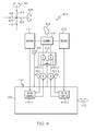
- FIG. 4 a functional block diagram of an exemplary active pilot inceptor system 400 is depicted.
- the depicted active pilot inceptor system 400 may be used to implement any one or more of the inceptors 210, 308 depicted in FIGS. 2 and 3 and described above, or any one or more of the inceptors previously mentioned but not explicitly described.
- the system 400 includes an inceptor 402 that is coupled to a suitable multiple degree-of freedom assembly 404.
- the inceptor 402 is configured to move, in response to input from either a pilot or a co-pilot, to a control position in a first direction or a second direction.
- the inceptor 402 is configured to rotate, from a null position 406 to a control position, about two perpendicular rotational axes, which in the depicted fixed wing embodiment are a pitch axis 408 and a roll axis 412. More specifically, if the pilot or co-pilot moves the inceptor 402 in a forward direction 414 or an aft direction 416, to thereby control aircraft pitch, the inceptor 402 rotates about the pitch axis 408.
- inceptor 402 rotates about the roll axis 412. It will additionally be appreciated that inceptor 402 may be moved in a combined forward-port direction, a combined forward-starboard direction, a combined aft-port direction, or a combined aft-starboard direction, and back to or through the null position 406, to thereby implement a combined aircraft pitch and roll maneuver.
- Inceptor sensors 424 are coupled to the inceptor 402 and supply inceptor signals to the motor control 212, the flight control(s) 202, or both.
- the inceptor sensors 424 may be variously implemented, but are preferably implemented using any one of numerous known force sensors, position sensors, or both.
- Some suitable force sensors include, but are not limited to, strain gage sensors, piezoelectric sensors, semiconductor sensors, or optical sensors, just to name a few
- suitable position sensors include, but are not limited to, absolute inceptor position sensors such as RVDTs, LVDTs, potentiometers, or optical sensors.
- At least one of the sensors 424 is configured to supply inceptor signals representative of a vector component of inceptor movement along the pitch axis 408, and another sensor 424 is configured to supply inceptor signals representative of a vector component of inceptor movement along the roll axis 412.
- the inceptor signals may be force signals, position signals, or both. In any case, the inceptor signals are supplied to the motor control 212.
- the motor control 212 upon receipt of the inceptor signals, supplies flight control commands 426 to the flight control(s) 202, to thereby implement a desired maneuver.
- the flight control(s) 202 may receive the inceptor signals directly from the inceptor sensors 424 and, in response, cause the desired maneuver to be implemented.
- the motor control 212 at least in the depicted embodiment, includes two inceptor motor controls 428 (e.g., 428-1, 428-2).
- the inceptor motor controls 428-1, 428-2 each selectively energize one of the user interface motors 432-1, 432-2.
- the motors 432 are each operable, upon being appropriately energized, generate torque and supply haptic feedback to the inceptor 402.
- the motors 432 are each implemented using multi-phase brushless DC machines.
- rotor commutation signals 434 associated with each motor 432 are supplied to that motor's associated motor control 428.
- the motors 432 are both coupled to the inceptor 402 via one or more lubricated gears 436-1, 436-2 that are preferably disposed in a gearbox housing 438. It is noted that for clarity the lubricated gears 436 are depicted as being disposed in a single gearbox housing 438; however, the gears 436 could be disposed in separate gearbox housings. In any case, as was previously noted, at relatively low temperatures, the friction within the active pilot inceptor system 400 increases due, in part, to the increased lubricant viscosity, and the tolerances of the gears 436 and non-illustrated motor bearings. Thus, the active pilot inceptor system 400 is additionally configured to implement a self warm-up function to sufficiently raise system temperatures. As will now be described, the system 400 implements the self warm-up function using heat generated by one or both of the motors 432.
- the motor controls 428 in addition to being configured to selectively energize the multi-phase motors 432 to generate torque, are also configured to selectively energize one or both of the multi-phase motors 432 in a manner that one or both of the multi-phase motors 432 do not generate torque.
- the multi-phase motors 432 when energized in this latter manner, will nonetheless generate heat due to resistive heating of the motor windings. By disposing the motors 432, gears 436, and/or gear housing 438 in sufficiently close proximity, the heat generated in the motors 432 will warm the lubricant, gears 436, and/or gear housing 438.
- the multi-phase motors 432 are preferably brushless DC machines. It is noted here that the motors 432 may be wye-wound, delta-wound, or implemented with independent phases. No matter the specific winding configuration, the motor controls 428, using known brushless DC motor commutation, control a minimum of six non-illustrated switching devices (e.g., FETs, IGBTs, etc.) to control current flow in the motor 432. Thus, for wye-wound or delta-wound motors, when the system 400 is implementing the self warm-up function, the motor controls 428 will control the switching devices to simultaneously connect one or two of the motor phases to a supply voltage, and one of the phases to return.
- the motor controls 428 will control the switching devices to simultaneously connect one or two of the motor phases to a supply voltage, and one of the phases to return.
- the motor controls 428 are additionally configured, during self warm-up of the system 400, to limit current flow through the motors 432 to a level that will prevent the motors 432 from overheating.
- the active pilot inceptor system 400 may be configured to initiate the self warm-up function either manually or, most preferably, automatically. If configured to initiate the self warm-up manually, the system 400 includes a self warm-up initiation switch 442 that may be selectively operated by the pilot (or co-pilot).
- the motor controls 428 are responsive to operation of the switch 442 to energize the associated motors 432, as described above, to generate heat but no torque. The motor controls 428 will continue to energize the associated motors 432 in this manner until the switch 442 is again operated or a predetermined reset temperature is reached.
- the system 400 additionally includes one or more suitable temperature sensors 444 (only one depicted). It may be appreciated that if the initiation switch 442 is included, a protective cover may preferably be included to prevent inadvertent operation of the switch 442, and thus inadvertent initiation of the of the self warm-up.
- the system 400 is preferably configured to initiate the self warm-up automatically. With this configuration, if the one or more temperature sensors 444 senses that the temperature adjacent one or both of the multi-phase motors 432 is less than a predetermined temperature, then the motor controls 428 will energize the associated motors 432, as described above, to generate heat but no torque. The motor controls 428 will continue to energize the associated motors 432 in this manner until the predetermined reset temperature, as sensed by the one or more temperature sensors 444, is reached.
- the system 400 is also preferably configured such that an appropriate signal is supplied to, for example, non-illustrated engine controllers to preclude engine startup whenever the self warm-up is being conducted. Similarly, the system 400 is preferably configured to preclude initiation of the self warm-up if the engine(s) is(are) running and/or the aircraft is on the ground.
- the system 400 may further include, if needed or desired, integral heaters 446 within the gearbox housing(s) 438.
- the heaters 446 may be energized from the motor control 212 and used to supplement the heat supplied from the motors 432.
- the heaters 446 may be variously implemented. For example, the heaters 446 could be bonded on heat strips or embedded within the gearbox housing(s) 438 when the housing(s) is(are) cast.
Applications Claiming Priority (1)
| Application Number | Priority Date | Filing Date | Title |
|---|---|---|---|
| US12/108,425 US8134328B2 (en) | 2008-04-23 | 2008-04-23 | Active pilot inceptor with self warm-up |
Publications (2)
| Publication Number | Publication Date |
|---|---|
| EP2112063A2 true EP2112063A2 (fr) | 2009-10-28 |
| EP2112063A3 EP2112063A3 (fr) | 2013-01-09 |
Family
ID=40756864
Family Applications (1)
| Application Number | Title | Priority Date | Filing Date |
|---|---|---|---|
| EP09157796A Withdrawn EP2112063A3 (fr) | 2008-04-23 | 2009-04-09 | Organe pilote actif avec auto-démarrage |
Country Status (2)
| Country | Link |
|---|---|
| US (1) | US8134328B2 (fr) |
| EP (1) | EP2112063A3 (fr) |
Cited By (1)
| Publication number | Priority date | Publication date | Assignee | Title |
|---|---|---|---|---|
| FR2984278A1 (fr) * | 2011-12-20 | 2013-06-21 | Thales Sa | Systeme d'assistance au pilote d'un aeronef par des moyens haptiques |
Families Citing this family (11)
| Publication number | Priority date | Publication date | Assignee | Title |
|---|---|---|---|---|
| US9156546B2 (en) * | 2008-03-11 | 2015-10-13 | The Boeing Company | Active-inceptor tactile-cueing hands-off rate-limit |
| US9150308B2 (en) * | 2012-02-10 | 2015-10-06 | Merlin Technology, Inc. | Rotorcraft autopilot system, components and methods |
| WO2013169320A2 (fr) | 2012-02-10 | 2013-11-14 | Merlin Technology, Inc. | Pilote automatique et procédés |
| GB2503671B (en) | 2012-07-03 | 2014-12-17 | Dyson Technology Ltd | Control of a brushless motor |
| WO2015175065A2 (fr) * | 2014-02-21 | 2015-11-19 | Eit Llc. | Contrôleur de tige de commande sans contact (ncm) |
| GB201409409D0 (en) * | 2014-05-28 | 2014-07-09 | Bae Systems Plc | Inceptor apparatus |
| WO2016048713A1 (fr) | 2014-09-22 | 2016-03-31 | Sikorsky Aircraft Corporation | Retour d'informations tactile pour contraintes de trajectoire en temps réel |
| GB2577720B (en) * | 2018-10-04 | 2023-04-19 | Bae Systems Plc | Oscilation system |
| US11524767B2 (en) * | 2021-03-31 | 2022-12-13 | Beta Air, Llc | Methods and systems for flight control configured for use in an electric aircraft |
| US20220326704A1 (en) * | 2021-03-31 | 2022-10-13 | Beta Air, Llc | Methods and systems for flight control configured for use in an electric aircraft |
| US11407496B1 (en) * | 2021-08-17 | 2022-08-09 | Beta Air, Llc | Systems and methods for redundant flight control in an aircraft |
Citations (2)
| Publication number | Priority date | Publication date | Assignee | Title |
|---|---|---|---|---|
| US5708336A (en) | 1996-08-21 | 1998-01-13 | Hughes Electronics | Thermal control system for a motor |
| EP1908685A2 (fr) | 2006-10-02 | 2008-04-09 | Honeywell International Inc. | Ensemble d'interface utilisateur actif équilibré par moteur |
Family Cites Families (19)
| Publication number | Priority date | Publication date | Assignee | Title |
|---|---|---|---|---|
| US3208237A (en) * | 1957-09-27 | 1965-09-28 | Carrier Corp | Refrigerating apparatus |
| US3445743A (en) * | 1966-08-10 | 1969-05-20 | M & B Electric Co Inc | Electric motor heating unit |
| US3582712A (en) * | 1970-04-27 | 1971-06-01 | M & B Electric Co Inc | Motor heating unit with power failure control responsive to an unheated condition of the motor |
| US3774096A (en) * | 1971-09-17 | 1973-11-20 | D Hann | Motor heater unit |
| US3717804A (en) * | 1972-04-28 | 1973-02-20 | Bechtel Int Corp | In-line motor heater circuit |
| US4135122A (en) * | 1977-05-25 | 1979-01-16 | Weyerhaeuser Company | Method and apparatus for heating electrical motors and like devices |
| US4195324A (en) * | 1978-07-26 | 1980-03-25 | Allen-Bradley Company | Heating circuit for an electric motor |
| JPS6152560A (ja) * | 1984-08-22 | 1986-03-15 | 株式会社日立製作所 | 空気調和機 |
| US5291113A (en) * | 1992-10-06 | 1994-03-01 | Honeywell Inc. | Servo coupled hand controllers |
| US5264768A (en) * | 1992-10-06 | 1993-11-23 | Honeywell, Inc. | Active hand controller feedback loop |
| US5347204A (en) * | 1992-10-06 | 1994-09-13 | Honeywell Inc. | Position dependent rate dampening in any active hand controller |
| US5694014A (en) * | 1995-08-22 | 1997-12-02 | Honeywell Inc. | Active hand controller redundancy and architecture |
| JPH11115467A (ja) * | 1997-10-13 | 1999-04-27 | Toyota Autom Loom Works Ltd | 自動車用空調装置 |
| DE29721563U1 (de) * | 1997-12-05 | 1999-01-14 | Sigma Laborzentrifugen Gmbh | Laborzentrifuge |
| JP3757745B2 (ja) * | 2000-03-30 | 2006-03-22 | ダイキン工業株式会社 | 予熱電力の制御方法及び予熱発生機構 |
| US7233476B2 (en) * | 2000-08-11 | 2007-06-19 | Immersion Corporation | Actuator thermal protection in haptic feedback devices |
| US6642682B1 (en) * | 2002-02-21 | 2003-11-04 | Active Power Inc. | Circuits and methods for preheating a rotor of a motor-generator device |
| US20030183728A1 (en) * | 2002-03-29 | 2003-10-02 | The Boeing Company | Aircraft control surface controller and associated method |
| US7451753B2 (en) * | 2006-04-21 | 2008-11-18 | Pratt & Whitney Canada Corp. | Pre-heating of a liquid in an aircraft reservoir |
-
2008
- 2008-04-23 US US12/108,425 patent/US8134328B2/en not_active Expired - Fee Related
-
2009
- 2009-04-09 EP EP09157796A patent/EP2112063A3/fr not_active Withdrawn
Patent Citations (2)
| Publication number | Priority date | Publication date | Assignee | Title |
|---|---|---|---|---|
| US5708336A (en) | 1996-08-21 | 1998-01-13 | Hughes Electronics | Thermal control system for a motor |
| EP1908685A2 (fr) | 2006-10-02 | 2008-04-09 | Honeywell International Inc. | Ensemble d'interface utilisateur actif équilibré par moteur |
Cited By (2)
| Publication number | Priority date | Publication date | Assignee | Title |
|---|---|---|---|---|
| FR2984278A1 (fr) * | 2011-12-20 | 2013-06-21 | Thales Sa | Systeme d'assistance au pilote d'un aeronef par des moyens haptiques |
| US9248904B2 (en) | 2011-12-20 | 2016-02-02 | Thales | System for assisting the pilot of an aircraft by haptic means |
Also Published As
| Publication number | Publication date |
|---|---|
| US20090266939A1 (en) | 2009-10-29 |
| US8134328B2 (en) | 2012-03-13 |
| EP2112063A3 (fr) | 2013-01-09 |
Similar Documents
| Publication | Publication Date | Title |
|---|---|---|
| US8134328B2 (en) | Active pilot inceptor with self warm-up | |
| US7759894B2 (en) | Cogless motor driven active user interface haptic feedback system | |
| US8240617B2 (en) | Variable damping of haptic feedback for a flight-attitude changing linkage of an aircraft | |
| US7658349B2 (en) | Pilot flight control stick haptic feedback system and method | |
| US8078340B2 (en) | Active user interface haptic feedback and linking control system using either force or position data | |
| US8170728B2 (en) | Rotorcraft control system | |
| EP1908685B1 (fr) | Ensemble d'interface utilisateur actif équilibré par moteur | |
| US20080156939A1 (en) | Active pilot flight control stick system with passive electromagnetic feedback | |
| US8002220B2 (en) | Rate limited active pilot inceptor system and method | |
| US8777152B2 (en) | Method and an aircraft provided with a swiveling tail rotor | |
| US8080966B2 (en) | Motor control architecture for simultaneously controlling multiple motors | |
| WO2018075414A1 (fr) | Multicoptère comprenant des rotors montés sur flèche | |
| US20070235594A1 (en) | Pilot flight control stick feedback system | |
| EP3186146B1 (fr) | Système de commande de pas | |
| WO2016054147A1 (fr) | Gestion de puissance entre un propulseur et un rotor coaxial d'un hélicoptère | |
| CN103241371B (zh) | 旋翼飞行器及控制组件 | |
| US20110148666A1 (en) | User interface passive haptic feedback system | |
| EP4192730A1 (fr) | Système et procédé d'ensembles de manche latéral et manette de commande de vol de véhicule à décollage et atterrissage verticaux (vtol) | |
| EP3363730B1 (fr) | Système et procédé de controle de volet et/ou d'aileron | |
| EP3326911B1 (fr) | Contrôle de la vitesse de rotor au moyen d'une commande de vitesse de rotor aval | |
| US8376269B2 (en) | Hydraulic valve, a hybrid helicopter provided with such a hydraulic valve, and a method implemented by the hydraulic valve | |
| EP3193230B1 (fr) | Compensateur activé par le pilote sur aéronef à commande électrique |
Legal Events
| Date | Code | Title | Description |
|---|---|---|---|
| PUAI | Public reference made under article 153(3) epc to a published international application that has entered the european phase |
Free format text: ORIGINAL CODE: 0009012 |
|
| 17P | Request for examination filed |
Effective date: 20090409 |
|
| AK | Designated contracting states |
Kind code of ref document: A2 Designated state(s): AT BE BG CH CY CZ DE DK EE ES FI FR GB GR HR HU IE IS IT LI LT LU LV MC MK MT NL NO PL PT RO SE SI SK TR |
|
| PUAL | Search report despatched |
Free format text: ORIGINAL CODE: 0009013 |
|
| AK | Designated contracting states |
Kind code of ref document: A3 Designated state(s): AT BE BG CH CY CZ DE DK EE ES FI FR GB GR HR HU IE IS IT LI LT LU LV MC MK MT NL NO PL PT RO SE SI SK TR |
|
| RIC1 | Information provided on ipc code assigned before grant |
Ipc: B64C 13/46 20060101AFI20121203BHEP |
|
| 17Q | First examination report despatched |
Effective date: 20130515 |
|
| GRAP | Despatch of communication of intention to grant a patent |
Free format text: ORIGINAL CODE: EPIDOSNIGR1 |
|
| INTG | Intention to grant announced |
Effective date: 20141020 |
|
| STAA | Information on the status of an ep patent application or granted ep patent |
Free format text: STATUS: THE APPLICATION IS DEEMED TO BE WITHDRAWN |
|
| 18D | Application deemed to be withdrawn |
Effective date: 20150303 |