EP2111945B1 - Tool revolver - Google Patents
Tool revolver Download PDFInfo
- Publication number
- EP2111945B1 EP2111945B1 EP09006780A EP09006780A EP2111945B1 EP 2111945 B1 EP2111945 B1 EP 2111945B1 EP 09006780 A EP09006780 A EP 09006780A EP 09006780 A EP09006780 A EP 09006780A EP 2111945 B1 EP2111945 B1 EP 2111945B1
- Authority
- EP
- European Patent Office
- Prior art keywords
- tool
- drive
- disc
- drive part
- station
- Prior art date
- Legal status (The legal status is an assumption and is not a legal conclusion. Google has not performed a legal analysis and makes no representation as to the accuracy of the status listed.)
- Not-in-force
Links
- 230000008878 coupling Effects 0.000 claims abstract description 20
- 238000010168 coupling process Methods 0.000 claims abstract description 20
- 238000005859 coupling reaction Methods 0.000 claims abstract description 20
- 230000002093 peripheral effect Effects 0.000 claims description 5
- 238000007789 sealing Methods 0.000 claims description 5
- 230000004323 axial length Effects 0.000 claims description 2
- 238000003754 machining Methods 0.000 description 8
- 238000007514 turning Methods 0.000 description 4
- 239000005068 cooling lubricant Substances 0.000 description 2
- 239000012530 fluid Substances 0.000 description 2
- 238000005299 abrasion Methods 0.000 description 1
- 230000015572 biosynthetic process Effects 0.000 description 1
- 230000000295 complement effect Effects 0.000 description 1
- 238000010586 diagram Methods 0.000 description 1
- 238000005553 drilling Methods 0.000 description 1
- 230000000977 initiatory effect Effects 0.000 description 1
- 238000003801 milling Methods 0.000 description 1
- 239000002245 particle Substances 0.000 description 1
- 230000000149 penetrating effect Effects 0.000 description 1
Images

Classifications
-
- B—PERFORMING OPERATIONS; TRANSPORTING
- B23—MACHINE TOOLS; METAL-WORKING NOT OTHERWISE PROVIDED FOR
- B23Q—DETAILS, COMPONENTS, OR ACCESSORIES FOR MACHINE TOOLS, e.g. ARRANGEMENTS FOR COPYING OR CONTROLLING; MACHINE TOOLS IN GENERAL CHARACTERISED BY THE CONSTRUCTION OF PARTICULAR DETAILS OR COMPONENTS; COMBINATIONS OR ASSOCIATIONS OF METAL-WORKING MACHINES, NOT DIRECTED TO A PARTICULAR RESULT
- B23Q5/00—Driving or feeding mechanisms; Control arrangements therefor
- B23Q5/02—Driving main working members
- B23Q5/04—Driving main working members rotary shafts, e.g. working-spindles
-
- B—PERFORMING OPERATIONS; TRANSPORTING
- B23—MACHINE TOOLS; METAL-WORKING NOT OTHERWISE PROVIDED FOR
- B23Q—DETAILS, COMPONENTS, OR ACCESSORIES FOR MACHINE TOOLS, e.g. ARRANGEMENTS FOR COPYING OR CONTROLLING; MACHINE TOOLS IN GENERAL CHARACTERISED BY THE CONSTRUCTION OF PARTICULAR DETAILS OR COMPONENTS; COMBINATIONS OR ASSOCIATIONS OF METAL-WORKING MACHINES, NOT DIRECTED TO A PARTICULAR RESULT
- B23Q2220/00—Machine tool components
- B23Q2220/002—Tool turrets
-
- Y—GENERAL TAGGING OF NEW TECHNOLOGICAL DEVELOPMENTS; GENERAL TAGGING OF CROSS-SECTIONAL TECHNOLOGIES SPANNING OVER SEVERAL SECTIONS OF THE IPC; TECHNICAL SUBJECTS COVERED BY FORMER USPC CROSS-REFERENCE ART COLLECTIONS [XRACs] AND DIGESTS
- Y10—TECHNICAL SUBJECTS COVERED BY FORMER USPC
- Y10T—TECHNICAL SUBJECTS COVERED BY FORMER US CLASSIFICATION
- Y10T29/00—Metal working
- Y10T29/51—Plural diverse manufacturing apparatus including means for metal shaping or assembling
- Y10T29/5152—Plural diverse manufacturing apparatus including means for metal shaping or assembling with turret mechanism
- Y10T29/5154—Plural diverse manufacturing apparatus including means for metal shaping or assembling with turret mechanism tool turret
- Y10T29/5155—Rotary tool holder
-
- Y—GENERAL TAGGING OF NEW TECHNOLOGICAL DEVELOPMENTS; GENERAL TAGGING OF CROSS-SECTIONAL TECHNOLOGIES SPANNING OVER SEVERAL SECTIONS OF THE IPC; TECHNICAL SUBJECTS COVERED BY FORMER USPC CROSS-REFERENCE ART COLLECTIONS [XRACs] AND DIGESTS
- Y10—TECHNICAL SUBJECTS COVERED BY FORMER USPC
- Y10T—TECHNICAL SUBJECTS COVERED BY FORMER US CLASSIFICATION
- Y10T29/00—Metal working
- Y10T29/51—Plural diverse manufacturing apparatus including means for metal shaping or assembling
- Y10T29/5152—Plural diverse manufacturing apparatus including means for metal shaping or assembling with turret mechanism
- Y10T29/5154—Plural diverse manufacturing apparatus including means for metal shaping or assembling with turret mechanism tool turret
- Y10T29/5158—Fluid operated
-
- Y—GENERAL TAGGING OF NEW TECHNOLOGICAL DEVELOPMENTS; GENERAL TAGGING OF CROSS-SECTIONAL TECHNOLOGIES SPANNING OVER SEVERAL SECTIONS OF THE IPC; TECHNICAL SUBJECTS COVERED BY FORMER USPC CROSS-REFERENCE ART COLLECTIONS [XRACs] AND DIGESTS
- Y10—TECHNICAL SUBJECTS COVERED BY FORMER USPC
- Y10T—TECHNICAL SUBJECTS COVERED BY FORMER US CLASSIFICATION
- Y10T29/00—Metal working
- Y10T29/51—Plural diverse manufacturing apparatus including means for metal shaping or assembling
- Y10T29/5152—Plural diverse manufacturing apparatus including means for metal shaping or assembling with turret mechanism
- Y10T29/5165—Plural diverse manufacturing apparatus including means for metal shaping or assembling with turret mechanism including rotating and/or locking means
- Y10T29/5167—Lock means for tool or work turrets
-
- Y—GENERAL TAGGING OF NEW TECHNOLOGICAL DEVELOPMENTS; GENERAL TAGGING OF CROSS-SECTIONAL TECHNOLOGIES SPANNING OVER SEVERAL SECTIONS OF THE IPC; TECHNICAL SUBJECTS COVERED BY FORMER USPC CROSS-REFERENCE ART COLLECTIONS [XRACs] AND DIGESTS
- Y10—TECHNICAL SUBJECTS COVERED BY FORMER USPC
- Y10T—TECHNICAL SUBJECTS COVERED BY FORMER US CLASSIFICATION
- Y10T74/00—Machine element or mechanism
- Y10T74/14—Rotary member or shaft indexing, e.g., tool or work turret
- Y10T74/1406—Rotary member or shaft indexing, e.g., tool or work turret with safety device or drive disconnect
-
- Y—GENERAL TAGGING OF NEW TECHNOLOGICAL DEVELOPMENTS; GENERAL TAGGING OF CROSS-SECTIONAL TECHNOLOGIES SPANNING OVER SEVERAL SECTIONS OF THE IPC; TECHNICAL SUBJECTS COVERED BY FORMER USPC CROSS-REFERENCE ART COLLECTIONS [XRACs] AND DIGESTS
- Y10—TECHNICAL SUBJECTS COVERED BY FORMER USPC
- Y10T—TECHNICAL SUBJECTS COVERED BY FORMER US CLASSIFICATION
- Y10T74/00—Machine element or mechanism
- Y10T74/14—Rotary member or shaft indexing, e.g., tool or work turret
- Y10T74/1494—Locking means
Definitions
- the invention relates to a tool turret with a base body to be mounted or attached to a machine tool according to the feature configuration of the preamble of claim 1.
- Tool turrets of this or similar type are known. That's how it shows US 6,704,983 B2 a tool turret intended for use in lathes, machining centers and similar devices, such as machine tools.
- the genus is the JP6103880 6-A
- the object of the invention is to provide a tool turret which is effectively protected against ingress of fluids and chips into the interior of the tool disk.
- each drive member for forming the drive connection with the tool holder of the tool station to be operated tool has an open on the outer periphery of the tool disk, Drehitwormiata having seat in which the drive shaft of the respective Tool holder can be used, and that the respective tool holder has an attachable to the outer periphery of the tool disc, preferably screwed tool carrier body in which the drive shaft is rotatably mounted, which in turn forms a seat for forming a drive connection between the drive shaft of the tool holder and an associated tool.
- the drive parts are designed so that they form a rotational body with circular cylindrical circumference over a majority of its axial length and in its the drive side inner coupling part adjacent end peripheral portion have at least one planar guide surface, which is part of a rotational position of the drive member Turning the tool disc forms fixing anti-rotation.
- the presence of a rotational position fixing the rotational position of the drive part when rotating the tool disc ensures that a trouble-free engagement between the drive part and the inner, drive-side coupling part can take place when the tool disc is rotated and a tool station enters the working position.
- the sealing arrangement which seals the inside of the tool disk to the outside at each tool station in cooperation with the drive part, is provided on the outer circular-cylindrical end region of the drive part adjacent to the outer circumference of the tool disk.
- a shaft seal for example in the form of a contacting radial shaft sealing ring, can be provided for this purpose.
- turret-side coupling part may be provided on the respective drive part, a diametral, continuous groove which is open at the interior of the tool disk facing the end of the drive member and their planar side walls to the at least one guide surface parallel planes.
- the guide surface on the drive parts can form part of a rotation of the drive member fixing the rotation of the tool disc fixing rotation, opens the possibility to adjust the drive member before the rotational movement of the tool disk in such a rotational position that the longitudinal axis of the groove in the direction of movement path Turning is aligned so that the coupling connection made by retracting the drive-side coupling part of the located inside the tool disk tool drive into the groove can be.
- a drive-side coupling part of the inner tool drive a drive pin having a rectangular outline, which is suitably receivable in the groove of the drive member and movable during rotational movements of the tool disk through the groove.
- the rotation of the drive parts may comprise a guide body which forms a concentric to the turret axis between the tool stations guideway extending along the traversed by the respective drive part when rotating the tool disc trajectory and along which the respective guide surface of the drive member when turning the tool disc fitting is.
- the tool drive located in the interior of the tool disk is an electric motor whose rotor shaft is concentric with the drive part of the tool station located in the working position and forms the drive pin at its shaft end
- an electric motor enabling electrical rotational position determination of the rotor and thus of the drive pin can be provided be used. Also exists the possibility of using corresponding sensors to make a rotational position for determining the rotor.
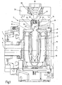
- Fig. 1 shows in a broken view only one end portion of a base body 1, which is connectable to a (not shown) machine tool and to which a designated as a whole by 3 tool disk is mounted.
- the base body 1 has a central, stationary hollow shaft 5, which defines a turret axis 7 about which the tool disk 3 is rotatable.
- the drive for the rotational movement about the turret axis 7 is effected by a tool disk drive not shown via a surrounding the hollow shaft 5 drive tube 9.
- the pertinent rotational movement is performed in the manner of a pivot drive.
- the tool disk 3 has a disk head housing 11 which, together with a front cover plate 13 bolted to the housing 11, encloses an interior 15 in the tool disk housing 11.
- the tool disk 3 has on its circumference a plurality of tool stations 17 which are arranged at equal mutual angular distances from one another and which are radially aligned relative to the turret axis 7.
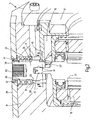
- the Fig. 1 and 2 show that one of the tool stations 17 is set to the working position in which a tool drive located in the interior 15 of the tool disk 3 can drive a machining tool mounted on the tool station in the working position via its drive-side coupling part.
- the tool drive has a located in the interior 15, with the main body 1 via the hollow shaft 5 fixedly connected electric motor 19, wherein the axis of rotation of its rotor shaft 21 is coaxial with the set in the working position tool station 17.
- the rotor shaft 21 forms in its end portion a drive pin 23, the, see Fig. 3 , has a rectangular cross-section.
- a drive member 25 is provided in each tool station.
- Each drive member 25 is rotatably supported in a respective through hole 26 of the tool disc housing 11, which extends in this in the radial direction, by means of a roller bearing 27, which is located on a circular cylindrical peripheral portion of the drive member 25.
- the inner wall of the through hole 26 and the circular cylindrical peripheral portion of the drive member 25 are respectively stepped so that shoulder surfaces 31 and 29 form, where the roller bearing 27 in cooperation with a seated in a circumferential groove of the drive member 25 retaining ring 33 (FIGS. Fig. 2 ) the drive member 25 axially secures.
- a closure plate 35 with a respective tool station 17 concentric opening 37 At the radially outer end extends in the region of each tool station 17 on the outside of the tool disk 3, a closure plate 35 with a respective tool station 17 concentric opening 37.
- the diameter of this opening 37 is greater than the outer diameter of the opening 37 extending in this circular cylindrical end portion 39th of the drive part 25.
- a shaft seal is arranged, which in the present case is a radial shaft sealing ring 41.
- each drive member 25 located at the radially inner end portion of each drive member 25 flats 43, which adjoin the circular cylindrical peripheral portion and each form a flat guide surface, which are part of a rotation for the respective drive member 25.
- This respective guide surface on the flattened portions 43 is guided during the rotational movement of the tool disk 3 along a guide body 45, which has an only in the region 47 (FIG. Fig. 3 ) formed on at least one tool station 17 interrupted track between the tool stations 17, at the drive parts 25 with the guide surface formed on the flats 43 guided in rotational movements of the tool disk 3 fitting and thus secured against rotation.
- the electric motor 19 has a device for determining the rotational position of the rotor shaft 21 and thus of the drive pin 23, so that the respective drive member 25 before it is moved out of the working position by rotating the tool disk 3, the in Fig. 3 shown rotational position occupies, in which the flats 43 are aligned with the guide track 45 on the guide body.
- a drive motor can serve a commercial electric servomotor.
- an angle gear with electric motor can be provided, which can be arranged outside the tool disk 3 (not shown).
- Fig. 1 shows a tool holder 53 conventional type (HSK type) without inserted into the tool holder 53 machining tool and prior to attachment to the outer closure plate 35 at the tool station 17 (for example, by screwing).
- HSK type conventional type
- FIG. 1 shows, is formed in such a tool holder 53 of the drive shaft 57 in the form of a rotational body which is mounted on the tool holder 53 by means of bearings 59 and has a stepped inner cavity 61 as a seat for the tool holder of the actual machining tool.
Landscapes
- Engineering & Computer Science (AREA)
- Mechanical Engineering (AREA)
- Automatic Tool Replacement In Machine Tools (AREA)
- Cutting Tools, Boring Holders, And Turrets (AREA)
- Eye Examination Apparatus (AREA)
- Orthopedics, Nursing, And Contraception (AREA)
- Mechanical Pencils And Projecting And Retracting Systems Therefor, And Multi-System Writing Instruments (AREA)
- Motorcycle And Bicycle Frame (AREA)
- Turning (AREA)
- Gripping On Spindles (AREA)
Abstract
Description
Die Erfindung bezieht sich auf einen Werkzeugrevolver mit einem an einer Werkzeugmaschine anzubringenden oder angebrachten Grundkörper gemäß der Merkmalsausgestaltung des Oberbegriffes des Patentanspruches 1.The invention relates to a tool turret with a base body to be mounted or attached to a machine tool according to the feature configuration of the preamble of claim 1.
Werkzeugrevolver dieser oder vergleichbarer Art sind bekannt. So zeigt die
Bei der Benutzung solcher Werkzeugrevolver handelt es sich bei den an den Werkzeugstationen des Revolverkopfes befindlichen Werkzeugen, die zum Einsatz kommen sollen, hauptsächlich um Werkzeuge zur spanabhebenden Bearbeitung, wie Bohr-, Dreh- oder Fräswerkzeuge, wobei zum Anpassen an die jeweilige Bearbeitungsaufgabe die Werkzeuge vom Maschinenbediener gewechselt werden. Regelmäßig kommen bei derartigen Bearbeitungsvorgängen Hilfsmedien, insbesondere in Form von Kühlschmierstoffen zum Einsatz und es besteht grundsätzlich die Gefahr, dass das dahingehende Kühlschmierstoffmittel zusammen mit den bei der Bearbeitung entstehenden Spänen in den Innenraum der Werkzeugscheibe gelangt, was den dort befindlichen Werkzeugantrieb zerstören kann. Letzteres gilt insbesondere dann, wenn durch das eindringende Fluid die Späne oder sonstige Schmutz- sowie Abriebpartikel mitgeführt werden und zu dem im Inneren der Werkzeugscheibe befindlichen Werkzeugantrieb gelangen.When using such tool turrets are located at the tool stations of the turret tools that are to be used, mainly to tools for machining, such as drilling, turning or milling tools, to adapt to the respective machining task, the tools of Machine operators are changed. Auxiliary media, in particular in the form of cooling lubricants, are regularly used in such machining operations, and there is generally the risk that the cooling lubricant thus obtained, together with the chips produced during machining, will enter the interior of the tool disk, which may destroy the tool drive located there. The latter applies in particular when the chips or other dirt and abrasion particles are carried along by the penetrating fluid and reach the tool drive located inside the tool disk.
Gattungsgebend ist die
Erfindungsgemäß ist diese Aufgabe durch einen Werkzeugrevolver gelöst, der die Merkmale des Patentanspruches 1 in seiner Gesamtheit aufweist.According to the invention this object is achieved by a tool turret having the features of claim 1 in its entirety.
Wie im kennzeichnenden Teil des Anspruches 1 angegeben, sieht die Erfindung vor, dass jedes Antriebsteil zur Bildung der Antriebsverbindung mit der Werkzeugaufnahme des an der betreffenden Werkzeugstation zu betreibenden Werkzeuges einen am Außenumfang der Werkzeugscheibe offenen, Drehmitnahmeelemente aufweisenden Sitz aufweist, in den der Antriebsschaft der betreffenden Werkzeugaufnahme einsetzbar ist, und dass die jeweilige Werkzeugaufnahme einen am Außenumfang der Werkzeugscheibe anbringbaren, vorzugsweise anschraubbaren Werkzeugträgerkörper aufweist, in dem der Antriebsschaft drehbar gelagert ist, der seinerseits einen Sitz zur Bildung einer Antriebsverbindung zwischen Antriebsschaft der Werkzeugaufnahme und einem zugeordneten Werkzeug bildet.As indicated in the characterizing part of claim 1, the invention provides that each drive member for forming the drive connection with the tool holder of the tool station to be operated tool has an open on the outer periphery of the tool disk, Drehitnahmeelemente having seat in which the drive shaft of the respective Tool holder can be used, and that the respective tool holder has an attachable to the outer periphery of the tool disc, preferably screwed tool carrier body in which the drive shaft is rotatably mounted, which in turn forms a seat for forming a drive connection between the drive shaft of the tool holder and an associated tool.
Bei vorteilhaften Ausführungsbeispielen der Erfindung sind die Antriebsteile so gestaltet, dass sie über einen Großteil ihrer axialen Länge einen Rotationskörper mit kreiszylindrischem Umfang bilden und in ihrem dem antriebsseitigen inneren Kupplungsteil benachbarten, endseitigen Umfangsabschnitt mindestens eine ebene Führungsfläche aufweisen, die Bestandteil einer die Drehposition des Antriebsteiles beim Drehen der Werkzeugscheibe fixierenden Verdrehsicherung bildet. Das Vorhandensein einer die Drehposition des Antriebsteiles beim Drehen der Werkzeugscheibe fixierenden Verdrehsicherung stellt sicher, dass beim Drehen der Werkzeugscheibe und dem Einlaufen einer Werkzeugstation in die Arbeitsposition ein störungsfreier Eingriff zwischen Antriebsteil und innerem, antriebsseitigem Kupplungsteil erfolgen kann.In advantageous embodiments of the invention, the drive parts are designed so that they form a rotational body with circular cylindrical circumference over a majority of its axial length and in its the drive side inner coupling part adjacent end peripheral portion have at least one planar guide surface, which is part of a rotational position of the drive member Turning the tool disc forms fixing anti-rotation. The presence of a rotational position fixing the rotational position of the drive part when rotating the tool disc ensures that a trouble-free engagement between the drive part and the inner, drive-side coupling part can take place when the tool disc is rotated and a tool station enters the working position.
Vorzugsweise ist die Dichtungsanordnung, die an jeder Werkzeugstation in Zusammenwirkung mit dem Antriebsteil das Innere der Werkzeugscheibe zur Außenseite hin abdichtet, an dem dem Außenumfang der Werkzeugscheibe benachbarten, äußeren kreiszylindrischen Endbereich des Antriebsteiles vorgesehen. In vorteilhafter Weise kann zu diesem Zweck eine Wellendichtung, beispielsweise in Form eines berührenden Radialwellendichtringes vorgesehen sein.Preferably, the sealing arrangement, which seals the inside of the tool disk to the outside at each tool station in cooperation with the drive part, is provided on the outer circular-cylindrical end region of the drive part adjacent to the outer circumference of the tool disk. In an advantageous manner, a shaft seal, for example in the form of a contacting radial shaft sealing ring, can be provided for this purpose.
Als werkzeugseitiges, insbesondere revolverseitiges Kupplungsteil kann am jeweiligen Antriebsteil eine diametrale, durchgehende Nut vorgesehen sein, die an dem dem Inneren der Werkzeugscheibe zugekehrten Ende des Antriebsteiles offen ist und deren ebene Seitenwände zu der zumindest einen Führungsfläche parallele Ebenen bilden.As a tool-side, in particular turret-side coupling part may be provided on the respective drive part, a diametral, continuous groove which is open at the interior of the tool disk facing the end of the drive member and their planar side walls to the at least one guide surface parallel planes.
Da die Führungsfläche an den Antriebsteilen Bestandteil einer die Drehposition des Antriebsteiles beim Drehen der Werkzeugscheibe fixierenden Verdrehsicherung bilden kann, eröffnet sich die Möglichkeit, das Antriebsteil vor der Drehbewegung der Werkzeugscheibe in eine solche Drehposition einzustellen, dass die Längsachse der Nut auf die Richtung der Bewegungsbahn beim Drehen ausgerichtet ist, so dass die Kupplungsverbindung durch Einfahren des antriebsseitigen Kupplungsteiles des im Inneren der Werkzeugscheibe befindlichen Werkzeugantriebes in die Nut hergestellt werden kann. Zu diesem Zweck kann als antriebsseitiges Kupplungsteil des inneren Werkzeugantriebes ein Antriebszapfen mit rechteckförmigem Umriß vorgesehen sein, der in der Nut des Antriebsteiles passend aufnehmbar und bei Drehbewegungen der Werkzeugscheibe durch die Nut hindurch bewegbar ist.Since the guide surface on the drive parts can form part of a rotation of the drive member fixing the rotation of the tool disc fixing rotation, opens the possibility to adjust the drive member before the rotational movement of the tool disk in such a rotational position that the longitudinal axis of the groove in the direction of movement path Turning is aligned so that the coupling connection made by retracting the drive-side coupling part of the located inside the tool disk tool drive into the groove can be. For this purpose may be provided as a drive-side coupling part of the inner tool drive, a drive pin having a rectangular outline, which is suitably receivable in the groove of the drive member and movable during rotational movements of the tool disk through the groove.
Die Verdrehsicherung für die Antriebsteile kann einen Führungskörper aufweisen, der zwischen den Werkzeugstationen eine zur Revolverachse konzentrisch verlaufende Führungsbahn bildet, die sich entlang der vom jeweiligen Antriebsteil beim Drehen der Werkzeugscheibe durchlaufenen Bewegungsbahn erstreckt und entlang deren die jeweilige Führungsfläche des Antriebsteiles beim Drehen der Werkzeugscheibe anliegend geführt ist.The rotation of the drive parts may comprise a guide body which forms a concentric to the turret axis between the tool stations guideway extending along the traversed by the respective drive part when rotating the tool disc trajectory and along which the respective guide surface of the drive member when turning the tool disc fitting is.
Damit bei derart drehpositioniertem Antriebsteil der Antriebszapfen des inneren Werkzeugantriebes in die Nut des in die Arbeitsposition jeweils einfahrenden Antriebsteiles störungsfrei eintreten kann, ist es erforderlich den Antriebszapfen des inneren Werkzeugantriebes vor Einleiten einer Drehbewegung der Werkzeugscheibe in eine Drehstellung zu bringen, bei der die Seitenwände der Nut des mit dem Antriebszapfen in Kupplungsverbindung stehenden Antriebsteiles und die jeweilige Führungsfläche des Antriebsteiles in zur Führungsbahn parallelen Ebenen liegen.Thus, in such drehpositioniertem drive part of the drive pin of the inner tool drive can enter the groove of the retracting into the working position each drive part trouble-free, it is necessary to bring the drive pin of the inner tool drive before initiating a rotational movement of the tool disk in a rotational position in which the side walls of the groove of the driving part, which is in coupling connection with the drive pin, and the respective guide surface of the drive part lie in planes parallel to the guide track.
Wenn es sich bei dem im Inneren der Werkzeugscheibe befindlichen Werkzeugantrieb um einen Elektromotor handelt, dessen Rotorwelle zum Antriebsteil der jeweils in der Arbeitsposition befindlichen Werkzeugstation konzentrisch ist und an ihrem Wellenende den Antriebszapfen bildet, kann ein eine elektrische Drehpositionsbestimmung des Rotors und damit des Antriebszapfens ermöglichender Elektromotor eingesetzt werden. Auch besteht die Möglichkeit über entsprechende Sensoren eine Drehposition zur Bestimmung des Rotors vorzunehmen.If the tool drive located in the interior of the tool disk is an electric motor whose rotor shaft is concentric with the drive part of the tool station located in the working position and forms the drive pin at its shaft end, an electric motor enabling electrical rotational position determination of the rotor and thus of the drive pin can be provided be used. Also exists the possibility of using corresponding sensors to make a rotational position for determining the rotor.
Nachstehend ist die Erfindung anhand eines in der Zeichnung dargestellten Ausführungsbeispieles im einzelnen erläutert. Es zeigen:
-
Fig. 1 einen Axialschnitt der an einem abgebrochen gezeichneten Grundkörper gelagerten Werkzeugscheibe des Ausführungsbeispieles des erfindungsgemäßen Werkzeugrevolvers, wobei eine auf die Arbeitsposition ausgerichtete Werkzeugstation sowie eine herkömmliche, an dieser Werkzeugstation anzubringende Werkzeugaufnahme (vor dem Anbringen und ohne darin befindliches Bearbeitungswerkzeug) gezeigt sind; -
Fig. 2 eine gegenüberFig. 1 vergrößert, abgebrochen, perspektivisch und schematisch vereinfacht gezeichnete Teildarstellung nur des Bereiches der in Arbeitsposition befindlichen Werkzeugstation und -
Fig. 3 eine schematische Diagrammdarstellung zur Erläuterung der Funktionsweise einer Verdrehsicherung anhand einer Schnittdarstellung entsprechend der Linie III-III vonFig. 2 .
-
Fig. 1 an axial section of the mounted on a broken drawn base body tool disk of the embodiment of the tool turret according to the invention, wherein a pointing to the working position tool station and a conventional, to be attached to this tool station tool holder (before attaching and without therein Bearbeitungswerkzeug) are shown; -
Fig. 2 one oppositeFig. 1 enlarged, aborted, perspective and schematically simplified drawn partial representation of only the area of the tool station located in the working position and -
Fig. 3 a schematic diagram representation for explaining the operation of a rotation with reference to a sectional view along the line III-III ofFig. 2 ,
Die Werkzeugscheibe 3 weist ein Scheibenkopfgehäuse 11 auf, das zusammen mit einer mit dem Gehäuse 11 verschraubten, frontseitigen Dekkelplatte 13 einen Innenraum 15 im Werkzeugscheibengehäuse 11 umschließt.The
Die Werkzeugscheibe 3 weist an ihrem Umfang eine Mehrzahl von in gleichen gegenseitigen Winkelabständen voneinander angeordneter Werkzeugstationen 17 auf, die, bezogen auf die Revolverachse 7, radial ausgerichtet sind. Die
Wie am deutlichsten aus
Am radial außenliegenden Ende erstreckt sich im Bereich jeder Werkzeugstation 17 an der Außenseite der Werkzeugscheibe 3 eine Verschlußplatte 35 mit einer zur jeweiligen Werkzeugstation 17 konzentrischen Öffnung 37. Der Durchmesser dieser Öffnung 37 ist größer als der Außendurchmesser des sich in dieser Öffnung 37 erstreckenden kreiszylindrischen Endabschnittes 39 des Antriebsteiles 25. In dem so gebildeten Zwischenraum ist eine Wellendichtung angeordnet, bei der es sich im vorliegenden Fall um einen Radialwellendichtring 41 handelt. Wie aus den Fig. zu ersehen ist, ist dadurch an jeder Werkzeugstation 17 die Öffnung 37 der äußeren Platte 35 gegenüber dem Antriebsteil 25 abgedichtet, so dass wiederum an jeder Werkzeugstation 17 eine Abdichtung zwischen dem Innenraum 15 der Werkzeugscheibe 3 und der Außenseite gegeben ist.At the radially outer end extends in the region of each
Wie am deutlichsten aus den
Um diesen Betriebsablauf zu ermöglichen, weist der Elektromotor 19 eine Einrichtung zur Bestimmung der Drehposition der Rotorwelle 21 und damit des Antriebszapfens 23 auf, so dass das jeweilige Antriebsteil 25, bevor es aus der Arbeitsposition durch Drehen der Werkzeugscheibe 3 heraus bewegt wird, die in
Außerdem befindet sich, wie ebenfalls aus
Wie die
Claims (9)
- A tool revolver comprising a base body (1) to be attached or attached to a machine tool and which defines a revolver axis (7), about which a tool disc (3) is rotatably mounted on the base body (1), which has a number of tool stations (17) distributed around its periphery and which, by rotating the tool disc (3), can be set in at least one working position respectively in which a tool drive (19) attached to the base body (1) and located in the interior (15) of the tool disc (3) comes with its drive side coupling part (23) into coupling engagement with a tool side drive
part for the drive of a tool which is located on the tool station (17) aligned to the working position, there being rotatably mounted in each tool station (17) a drive part (25) forming the coupling part on the tool side, with which the tool receiving element (53) of the respective tool operable on the tool station (17) can be brought into drive connection, and on each drive part (25) a sealing arrangement (41) being provided which on the respective tool station (17) seals the interior (15) of the tool disc (3) from the outside, characterised in that every drive part (25) has, in order to form the drive connection to the tool receiving element (53) of the tool to be operated on the tool station (17) in question, a seat open on the outer periphery of the tool disc (3) and having rotary entrainment elements (55) into which the drive shaft (57) of the tool receiving element (53) in question can be inserted, and that the respective tool receiving element (53) has a tool carrier element that can be attached, preferably screwed, to the outer periphery of the tool disc (3) and in which the drive shaft (57) is rotatably mounted, which itself forms a seat (61) in order to form a drive connection between the drive shaft (57) of the tool receiving element (53) and an assigned tool. - The tool revolver according to Claim 1, characterised in that each drive part (25) forms over a large part of its axial length a rotation body with a circular cylindrical circumference, and in its end side peripheral section adjacent to the drive side coupling part (23) of the inner tool drive (19) has at least one level guide surface (43) which forms a component of an anti-twist device fixing the rotary position of the drive part (25) upon rotating the tool disc (3).
- The tool revolver according to Claim 2, characterised in that the sealing arrangement (41) is provided on the outer circular cylindrical end region (39) of the drive part (25) adjacent to the outer periphery of the tool disc (3).
- The tool revolver according to Claim 2 or 3, characterised in that there is provided as a tool side coupling part on the respective drive part (25) a diametric, continuous groove (49) which is open on the end of the drive part (25) facing towards the interior (15) of the tool disc (3), and the level side walls (51) of which form planes parallel to the at least one guide surface (43).
- The tool revolver according to Claim 4, characterised in that the drive side coupling part (23) of the tool drive (19) located in the interior of the tool disc (3) has at least one drive pin with a rectangular cross-section which can be received fitting in the groove (49) of the drive part (25), and with rotating movements of the tool disc (3) can be moved through the groove (49).
- The tool revolver according to Claim 5, characterised in that the anti-twist device for the drive parts (25) has a guide element which forms between the tool stations (17) a guide track (45) extending concentrically to the revolver axis (7) and which extends along the trajectory through which the respective drive part (25) passes upon rotation of the tool disc (3), and along which the respective guide surface (43) of the drive part (25) is guided adjacently upon rotation of the tool disc (3).
- The tool revolver according to Claim 6, characterised by a device for the rotary positioning of the drive-side coupling part of the tool drive (19) such that the drive pin (23) of the latter brings the drive part (25) into a rotary position in which the side walls (51) of the groove (49) and the respective guide surface (43) of the drive part (25) lie in planes parallel to the guide track (45).
- The tool revolver according to Claim 7, characterised in that the tool drive located in the interior (15) of the tool disc (3) has an electric motor (19) the rotor shaft (21) of which is concentric to the drive part (25) of the tool station (17) respectively located in the working position and forms on its shaft end the drive pin (23).
- The tool revolver according to Claim 8, characterised in that an electric motor (19) enabling electrical rotary position determination of the rotor (21) is provided.
Applications Claiming Priority (2)
| Application Number | Priority Date | Filing Date | Title |
|---|---|---|---|
| DE102005033890A DE102005033890A1 (en) | 2005-07-20 | 2005-07-20 | tool turret |
| EP06742630A EP1910021B1 (en) | 2005-07-20 | 2006-04-21 | Tool revolver |
Related Parent Applications (2)
| Application Number | Title | Priority Date | Filing Date |
|---|---|---|---|
| EP06742630.4 Division | 2006-04-21 | ||
| EP06742630A Division EP1910021B1 (en) | 2005-07-20 | 2006-04-21 | Tool revolver |
Publications (2)
| Publication Number | Publication Date |
|---|---|
| EP2111945A1 EP2111945A1 (en) | 2009-10-28 |
| EP2111945B1 true EP2111945B1 (en) | 2010-11-10 |
Family
ID=36602670
Family Applications (2)
| Application Number | Title | Priority Date | Filing Date |
|---|---|---|---|
| EP06742630A Not-in-force EP1910021B1 (en) | 2005-07-20 | 2006-04-21 | Tool revolver |
| EP09006780A Not-in-force EP2111945B1 (en) | 2005-07-20 | 2006-04-21 | Tool revolver |
Family Applications Before (1)
| Application Number | Title | Priority Date | Filing Date |
|---|---|---|---|
| EP06742630A Not-in-force EP1910021B1 (en) | 2005-07-20 | 2006-04-21 | Tool revolver |
Country Status (5)
| Country | Link |
|---|---|
| US (1) | US7971328B2 (en) |
| EP (2) | EP1910021B1 (en) |
| AT (1) | ATE487558T1 (en) |
| DE (3) | DE102005033890A1 (en) |
| WO (1) | WO2007009515A1 (en) |
Families Citing this family (21)
| Publication number | Priority date | Publication date | Assignee | Title |
|---|---|---|---|---|
| DE102007043777A1 (en) | 2007-09-13 | 2009-04-02 | Sauter Feinmechanik Gmbh | Spindle head for machine tools |
| DE102007043775A1 (en) | 2007-09-13 | 2009-03-19 | Sauter Feinmechanik Gmbh | tool turret |
| DE102008045181B3 (en) | 2008-08-30 | 2010-01-07 | Sauter Feinmechanik Gmbh | tool turret |
| DE102009033805A1 (en) * | 2009-07-18 | 2011-01-27 | Sauter Feinmechanik Gmbh | alignment |
| CN102858491B (en) * | 2010-05-28 | 2016-05-04 | 索特精密机械有限公司 | Cutter capstan head |
| ITRM20130419A1 (en) | 2013-07-16 | 2015-01-17 | Baldaccini Mario | TURRET FOR MACHINE TOOL. |
| JP6480744B2 (en) * | 2015-02-09 | 2019-03-13 | Dmg森精機株式会社 | Machine Tools |
| DE102015003893A1 (en) | 2015-03-26 | 2016-09-29 | Sauter Feinmechanik Gmbh | tool drive |
| DE102015003892A1 (en) | 2015-03-26 | 2016-09-29 | Sauter Feinmechanik Gmbh | tool turret |
| JP6425601B2 (en) * | 2015-03-31 | 2018-11-21 | シチズン時計株式会社 | Tool post of machine tool |
| DE102015004268B4 (en) | 2015-04-01 | 2017-02-23 | Sauter Feinmechanik Gmbh | tool turret |
| DE102015012938B4 (en) | 2015-10-01 | 2020-08-13 | Sauter Feinmechanik Gmbh | Fixing device |
| DE102016009895A1 (en) * | 2016-08-13 | 2018-02-15 | Sauter Feinmechanik Gmbh | Device for releasably fixing modules |
| DE102016010700A1 (en) | 2016-09-03 | 2018-03-08 | Sauter Feinmechanik Gmbh | coupling device |
| DE102017007648A1 (en) | 2017-08-12 | 2019-02-14 | Sauter Feinmechanik Gmbh | tool turret |
| DE102018004677A1 (en) * | 2018-06-12 | 2019-12-12 | Sauter Feinmechanik Gmbh | tool turret |
| DE102019000383A1 (en) | 2019-01-19 | 2020-07-23 | Sauter Feinmechanik Gmbh | Positioning device |
| DE102019000379A1 (en) | 2019-01-19 | 2020-07-23 | Sauter Feinmechanik Gmbh | Safety device |
| DE102019003111B4 (en) | 2019-04-30 | 2022-03-03 | Zeitfracht Gmbh & Co. Kgaa | tool changing device |
| DE102019009289B3 (en) | 2019-04-30 | 2022-03-10 | Zeitfracht Gmbh & Co. Kgaa | tool changing device |
| DE102019006482A1 (en) | 2019-09-10 | 2021-03-11 | Sauter Feinmechanik Gmbh | Communication system and machine device |
Family Cites Families (9)
| Publication number | Priority date | Publication date | Assignee | Title |
|---|---|---|---|---|
| US3023677A (en) * | 1960-01-29 | 1962-03-06 | Brown & Sharpe Mfg | Machine tool with tool carrier |
| DE3216891A1 (en) * | 1982-05-06 | 1983-11-10 | Index-Werke Kg Hahn & Tessky, 7300 Esslingen | MULTI-SPINDLE REVOLER TURNING MACHINE |
| JPS6138806A (en) * | 1984-07-31 | 1986-02-24 | Robotsuto Giken Kk | Turret head unit |
| DE3929136C1 (en) * | 1989-09-01 | 1991-04-04 | Emag Maschinenfabrik Gmbh, 7335 Salach, De | |
| DE4125003A1 (en) * | 1991-07-27 | 1993-01-28 | Index Werke Kg Hahn & Tessky | TOOL REVOLVER, IN PARTICULAR LATHE |
| WO1997043069A1 (en) * | 1996-05-09 | 1997-11-20 | Witzig & Frank Turmatic Gmbh | Tool revolver and machine tool |
| DE19919236A1 (en) * | 1999-04-28 | 2000-11-09 | Traub Drehmaschinen Gmbh | Tool carriers for machine tools and tool arrangement for machine tools |
| JP2001341009A (en) * | 2000-05-31 | 2001-12-11 | Nitto Seiko Co Ltd | Automatic tool changing device |
| JP2003071615A (en) * | 2001-08-30 | 2003-03-12 | Mori Seiki Co Ltd | Turret tool rest |
-
2005
- 2005-07-20 DE DE102005033890A patent/DE102005033890A1/en not_active Withdrawn
-
2006
- 2006-04-21 AT AT09006780T patent/ATE487558T1/en active
- 2006-04-21 DE DE502006008305T patent/DE502006008305D1/en active Active
- 2006-04-21 EP EP06742630A patent/EP1910021B1/en not_active Not-in-force
- 2006-04-21 EP EP09006780A patent/EP2111945B1/en not_active Not-in-force
- 2006-04-21 US US11/921,302 patent/US7971328B2/en not_active Expired - Fee Related
- 2006-04-21 WO PCT/EP2006/003667 patent/WO2007009515A1/en not_active Application Discontinuation
- 2006-04-21 DE DE502006004324T patent/DE502006004324D1/en active Active
Also Published As
| Publication number | Publication date |
|---|---|
| WO2007009515A1 (en) | 2007-01-25 |
| US20100029451A1 (en) | 2010-02-04 |
| DE102005033890A1 (en) | 2007-01-25 |
| US7971328B2 (en) | 2011-07-05 |
| DE502006004324D1 (en) | 2009-09-03 |
| EP1910021B1 (en) | 2009-07-22 |
| EP1910021A1 (en) | 2008-04-16 |
| ATE487558T1 (en) | 2010-11-15 |
| DE502006008305D1 (en) | 2010-12-23 |
| EP2111945A1 (en) | 2009-10-28 |
Similar Documents
| Publication | Publication Date | Title |
|---|---|---|
| EP2111945B1 (en) | Tool revolver | |
| EP0461357B1 (en) | Tool holding turret | |
| EP2561145B1 (en) | Rotary device for an attachment on a machine | |
| DE4100186A1 (en) | HAND MACHINE TOOL WITH REMOVABLE TOOL HOLDER | |
| DE2715357A1 (en) | TOOL MOUNTING DEVICE | |
| EP0270768B2 (en) | Incrementor absolute revolution sensor with clamping means | |
| DE9202252U1 (en) | Tool turret | |
| DE19922320C5 (en) | Tool for a cutting, mining or road milling machine | |
| EP2478996B1 (en) | Tool changer | |
| DE102005038193B4 (en) | Tank cleaning device | |
| EP3444065A2 (en) | Neutral point tensioning module | |
| EP1452266B1 (en) | Workpiece holder for elongated work pieces | |
| DE19519639A1 (en) | Machine tool chuck with axially moving jaws | |
| DE19852049A1 (en) | Tool head with spindle bearing | |
| DE102018007084A1 (en) | Connecting device | |
| EP1245329A1 (en) | Device for the supply of coolant/lubricant to a rotating tool with internal coolant passage | |
| DE102020003927A1 (en) | Driven tool carrier | |
| EP3072634B1 (en) | Tool revolver | |
| DE19605068C2 (en) | Screw connection | |
| DE3702216A1 (en) | Cooling-lubricant feed device for rotating cutting tools | |
| DE20200951U1 (en) | Small milling fixture for electrode cap milling cutters has a window-type sliding guide which runs through the entire milling head | |
| DE102012004605B4 (en) | Process and tool for machining bearing points in a brake caliper | |
| EP3824160B1 (en) | Roller cutter | |
| DE19938435C2 (en) | cleaning device | |
| DE20307471U1 (en) | Hub and shaft connection for tool clamping unit of machine tool, comprising insertion aid working with ball elements |
Legal Events
| Date | Code | Title | Description |
|---|---|---|---|
| PUAI | Public reference made under article 153(3) epc to a published international application that has entered the european phase |
Free format text: ORIGINAL CODE: 0009012 |
|
| AC | Divisional application: reference to earlier application |
Ref document number: 1910021 Country of ref document: EP Kind code of ref document: P |
|
| AK | Designated contracting states |
Kind code of ref document: A1 Designated state(s): AT BE BG CH CY CZ DE DK EE ES FI FR GB GR HU IE IS IT LI LT LU LV MC NL PL PT RO SE SI SK TR |
|
| 17P | Request for examination filed |
Effective date: 20091027 |
|
| GRAP | Despatch of communication of intention to grant a patent |
Free format text: ORIGINAL CODE: EPIDOSNIGR1 |
|
| GRAS | Grant fee paid |
Free format text: ORIGINAL CODE: EPIDOSNIGR3 |
|
| GRAA | (expected) grant |
Free format text: ORIGINAL CODE: 0009210 |
|
| AC | Divisional application: reference to earlier application |
Ref document number: 1910021 Country of ref document: EP Kind code of ref document: P |
|
| AK | Designated contracting states |
Kind code of ref document: B1 Designated state(s): AT BE BG CH CY CZ DE DK EE ES FI FR GB GR HU IE IS IT LI LT LU LV MC NL PL PT RO SE SI SK TR |
|
| REG | Reference to a national code |
Ref country code: GB Ref legal event code: FG4D Free format text: NOT ENGLISH |
|
| REG | Reference to a national code |
Ref country code: CH Ref legal event code: EP |
|
| REG | Reference to a national code |
Ref country code: IE Ref legal event code: FG4D Free format text: LANGUAGE OF EP DOCUMENT: GERMAN |
|
| REF | Corresponds to: |
Ref document number: 502006008305 Country of ref document: DE Date of ref document: 20101223 Kind code of ref document: P |
|
| REG | Reference to a national code |
Ref country code: NL Ref legal event code: VDEP Effective date: 20101110 |
|
| LTIE | Lt: invalidation of european patent or patent extension |
Effective date: 20101110 |
|
| PG25 | Lapsed in a contracting state [announced via postgrant information from national office to epo] |
Ref country code: LT Free format text: LAPSE BECAUSE OF FAILURE TO SUBMIT A TRANSLATION OF THE DESCRIPTION OR TO PAY THE FEE WITHIN THE PRESCRIBED TIME-LIMIT Effective date: 20101110 |
|
| PG25 | Lapsed in a contracting state [announced via postgrant information from national office to epo] |
Ref country code: FI Free format text: LAPSE BECAUSE OF FAILURE TO SUBMIT A TRANSLATION OF THE DESCRIPTION OR TO PAY THE FEE WITHIN THE PRESCRIBED TIME-LIMIT Effective date: 20101110 Ref country code: SI Free format text: LAPSE BECAUSE OF FAILURE TO SUBMIT A TRANSLATION OF THE DESCRIPTION OR TO PAY THE FEE WITHIN THE PRESCRIBED TIME-LIMIT Effective date: 20101110 Ref country code: BG Free format text: LAPSE BECAUSE OF FAILURE TO SUBMIT A TRANSLATION OF THE DESCRIPTION OR TO PAY THE FEE WITHIN THE PRESCRIBED TIME-LIMIT Effective date: 20110210 Ref country code: NL Free format text: LAPSE BECAUSE OF FAILURE TO SUBMIT A TRANSLATION OF THE DESCRIPTION OR TO PAY THE FEE WITHIN THE PRESCRIBED TIME-LIMIT Effective date: 20101110 Ref country code: IS Free format text: LAPSE BECAUSE OF FAILURE TO SUBMIT A TRANSLATION OF THE DESCRIPTION OR TO PAY THE FEE WITHIN THE PRESCRIBED TIME-LIMIT Effective date: 20110310 Ref country code: SE Free format text: LAPSE BECAUSE OF FAILURE TO SUBMIT A TRANSLATION OF THE DESCRIPTION OR TO PAY THE FEE WITHIN THE PRESCRIBED TIME-LIMIT Effective date: 20101110 Ref country code: PT Free format text: LAPSE BECAUSE OF FAILURE TO SUBMIT A TRANSLATION OF THE DESCRIPTION OR TO PAY THE FEE WITHIN THE PRESCRIBED TIME-LIMIT Effective date: 20110310 Ref country code: CY Free format text: LAPSE BECAUSE OF FAILURE TO SUBMIT A TRANSLATION OF THE DESCRIPTION OR TO PAY THE FEE WITHIN THE PRESCRIBED TIME-LIMIT Effective date: 20101110 Ref country code: LV Free format text: LAPSE BECAUSE OF FAILURE TO SUBMIT A TRANSLATION OF THE DESCRIPTION OR TO PAY THE FEE WITHIN THE PRESCRIBED TIME-LIMIT Effective date: 20101110 |
|
| REG | Reference to a national code |
Ref country code: IE Ref legal event code: FD4D |
|
| PG25 | Lapsed in a contracting state [announced via postgrant information from national office to epo] |
Ref country code: GR Free format text: LAPSE BECAUSE OF FAILURE TO SUBMIT A TRANSLATION OF THE DESCRIPTION OR TO PAY THE FEE WITHIN THE PRESCRIBED TIME-LIMIT Effective date: 20110211 |
|
| PG25 | Lapsed in a contracting state [announced via postgrant information from national office to epo] |
Ref country code: EE Free format text: LAPSE BECAUSE OF FAILURE TO SUBMIT A TRANSLATION OF THE DESCRIPTION OR TO PAY THE FEE WITHIN THE PRESCRIBED TIME-LIMIT Effective date: 20101110 Ref country code: ES Free format text: LAPSE BECAUSE OF FAILURE TO SUBMIT A TRANSLATION OF THE DESCRIPTION OR TO PAY THE FEE WITHIN THE PRESCRIBED TIME-LIMIT Effective date: 20110221 Ref country code: IE Free format text: LAPSE BECAUSE OF FAILURE TO SUBMIT A TRANSLATION OF THE DESCRIPTION OR TO PAY THE FEE WITHIN THE PRESCRIBED TIME-LIMIT Effective date: 20101110 Ref country code: CZ Free format text: LAPSE BECAUSE OF FAILURE TO SUBMIT A TRANSLATION OF THE DESCRIPTION OR TO PAY THE FEE WITHIN THE PRESCRIBED TIME-LIMIT Effective date: 20101110 |
|
| PG25 | Lapsed in a contracting state [announced via postgrant information from national office to epo] |
Ref country code: SK Free format text: LAPSE BECAUSE OF FAILURE TO SUBMIT A TRANSLATION OF THE DESCRIPTION OR TO PAY THE FEE WITHIN THE PRESCRIBED TIME-LIMIT Effective date: 20101110 Ref country code: RO Free format text: LAPSE BECAUSE OF FAILURE TO SUBMIT A TRANSLATION OF THE DESCRIPTION OR TO PAY THE FEE WITHIN THE PRESCRIBED TIME-LIMIT Effective date: 20101110 Ref country code: PL Free format text: LAPSE BECAUSE OF FAILURE TO SUBMIT A TRANSLATION OF THE DESCRIPTION OR TO PAY THE FEE WITHIN THE PRESCRIBED TIME-LIMIT Effective date: 20101110 Ref country code: DK Free format text: LAPSE BECAUSE OF FAILURE TO SUBMIT A TRANSLATION OF THE DESCRIPTION OR TO PAY THE FEE WITHIN THE PRESCRIBED TIME-LIMIT Effective date: 20101110 |
|
| PLBE | No opposition filed within time limit |
Free format text: ORIGINAL CODE: 0009261 |
|
| STAA | Information on the status of an ep patent application or granted ep patent |
Free format text: STATUS: NO OPPOSITION FILED WITHIN TIME LIMIT |
|
| 26N | No opposition filed |
Effective date: 20110811 |
|
| BERE | Be: lapsed |
Owner name: SAUTER FEINMECHANIK G.M.B.H. Effective date: 20110430 |
|
| PG25 | Lapsed in a contracting state [announced via postgrant information from national office to epo] |
Ref country code: MC Free format text: LAPSE BECAUSE OF NON-PAYMENT OF DUE FEES Effective date: 20110430 |
|
| REG | Reference to a national code |
Ref country code: CH Ref legal event code: PL |
|
| REG | Reference to a national code |
Ref country code: DE Ref legal event code: R097 Ref document number: 502006008305 Country of ref document: DE Effective date: 20110811 |
|
| GBPC | Gb: european patent ceased through non-payment of renewal fee |
Effective date: 20110421 |
|
| REG | Reference to a national code |
Ref country code: FR Ref legal event code: ST Effective date: 20111230 |
|
| PG25 | Lapsed in a contracting state [announced via postgrant information from national office to epo] |
Ref country code: BE Free format text: LAPSE BECAUSE OF NON-PAYMENT OF DUE FEES Effective date: 20110430 Ref country code: FR Free format text: LAPSE BECAUSE OF NON-PAYMENT OF DUE FEES Effective date: 20110502 Ref country code: CH Free format text: LAPSE BECAUSE OF NON-PAYMENT OF DUE FEES Effective date: 20110430 Ref country code: LI Free format text: LAPSE BECAUSE OF NON-PAYMENT OF DUE FEES Effective date: 20110430 |
|
| PG25 | Lapsed in a contracting state [announced via postgrant information from national office to epo] |
Ref country code: GB Free format text: LAPSE BECAUSE OF NON-PAYMENT OF DUE FEES Effective date: 20110421 |
|
| REG | Reference to a national code |
Ref country code: AT Ref legal event code: MM01 Ref document number: 487558 Country of ref document: AT Kind code of ref document: T Effective date: 20110421 |
|
| PG25 | Lapsed in a contracting state [announced via postgrant information from national office to epo] |
Ref country code: AT Free format text: LAPSE BECAUSE OF NON-PAYMENT OF DUE FEES Effective date: 20110421 |
|
| PG25 | Lapsed in a contracting state [announced via postgrant information from national office to epo] |
Ref country code: LU Free format text: LAPSE BECAUSE OF NON-PAYMENT OF DUE FEES Effective date: 20110421 |
|
| PGFP | Annual fee paid to national office [announced via postgrant information from national office to epo] |
Ref country code: DE Payment date: 20130221 Year of fee payment: 8 |
|
| PGFP | Annual fee paid to national office [announced via postgrant information from national office to epo] |
Ref country code: IT Payment date: 20130417 Year of fee payment: 8 |
|
| PG25 | Lapsed in a contracting state [announced via postgrant information from national office to epo] |
Ref country code: TR Free format text: LAPSE BECAUSE OF FAILURE TO SUBMIT A TRANSLATION OF THE DESCRIPTION OR TO PAY THE FEE WITHIN THE PRESCRIBED TIME-LIMIT Effective date: 20101110 |
|
| PG25 | Lapsed in a contracting state [announced via postgrant information from national office to epo] |
Ref country code: HU Free format text: LAPSE BECAUSE OF FAILURE TO SUBMIT A TRANSLATION OF THE DESCRIPTION OR TO PAY THE FEE WITHIN THE PRESCRIBED TIME-LIMIT Effective date: 20101110 |
|
| REG | Reference to a national code |
Ref country code: DE Ref legal event code: R119 Ref document number: 502006008305 Country of ref document: DE |
|
| REG | Reference to a national code |
Ref country code: DE Ref legal event code: R119 Ref document number: 502006008305 Country of ref document: DE Effective date: 20141101 |
|
| PG25 | Lapsed in a contracting state [announced via postgrant information from national office to epo] |
Ref country code: DE Free format text: LAPSE BECAUSE OF NON-PAYMENT OF DUE FEES Effective date: 20141101 |
|
| PG25 | Lapsed in a contracting state [announced via postgrant information from national office to epo] |
Ref country code: IT Free format text: LAPSE BECAUSE OF NON-PAYMENT OF DUE FEES Effective date: 20140421 |