EP2111944A2 - Repair method and repaired article - Google Patents
Repair method and repaired article Download PDFInfo
- Publication number
- EP2111944A2 EP2111944A2 EP09250714A EP09250714A EP2111944A2 EP 2111944 A2 EP2111944 A2 EP 2111944A2 EP 09250714 A EP09250714 A EP 09250714A EP 09250714 A EP09250714 A EP 09250714A EP 2111944 A2 EP2111944 A2 EP 2111944A2
- Authority
- EP
- European Patent Office
- Prior art keywords
- article
- repair section
- section
- repair
- recited
- Prior art date
- Legal status (The legal status is an assumption and is not a legal conclusion. Google has not performed a legal analysis and makes no representation as to the accuracy of the status listed.)
- Granted
Links
Images


Classifications
-
- F—MECHANICAL ENGINEERING; LIGHTING; HEATING; WEAPONS; BLASTING
- F01—MACHINES OR ENGINES IN GENERAL; ENGINE PLANTS IN GENERAL; STEAM ENGINES
- F01D—NON-POSITIVE DISPLACEMENT MACHINES OR ENGINES, e.g. STEAM TURBINES
- F01D5/00—Blades; Blade-carrying members; Heating, heat-insulating, cooling or antivibration means on the blades or the members
- F01D5/005—Repairing methods or devices
-
- B—PERFORMING OPERATIONS; TRANSPORTING
- B21—MECHANICAL METAL-WORKING WITHOUT ESSENTIALLY REMOVING MATERIAL; PUNCHING METAL
- B21K—MAKING FORGED OR PRESSED METAL PRODUCTS, e.g. HORSE-SHOES, RIVETS, BOLTS OR WHEELS
- B21K3/00—Making engine or like machine parts not covered by sub-groups of B21K1/00; Making propellers or the like
- B21K3/04—Making engine or like machine parts not covered by sub-groups of B21K1/00; Making propellers or the like blades, e.g. for turbines; Upsetting of blade roots
-
- B—PERFORMING OPERATIONS; TRANSPORTING
- B23—MACHINE TOOLS; METAL-WORKING NOT OTHERWISE PROVIDED FOR
- B23P—METAL-WORKING NOT OTHERWISE PROVIDED FOR; COMBINED OPERATIONS; UNIVERSAL MACHINE TOOLS
- B23P6/00—Restoring or reconditioning objects
- B23P6/002—Repairing turbine components, e.g. moving or stationary blades, rotors
- B23P6/005—Repairing turbine components, e.g. moving or stationary blades, rotors using only replacement pieces of a particular form
-
- B—PERFORMING OPERATIONS; TRANSPORTING
- B23—MACHINE TOOLS; METAL-WORKING NOT OTHERWISE PROVIDED FOR
- B23P—METAL-WORKING NOT OTHERWISE PROVIDED FOR; COMBINED OPERATIONS; UNIVERSAL MACHINE TOOLS
- B23P9/00—Treating or finishing surfaces mechanically, with or without calibrating, primarily to resist wear or impact, e.g. smoothing or roughening turbine blades or bearings; Features of such surfaces not otherwise provided for, their treatment being unspecified
- B23P9/02—Treating or finishing by applying pressure, e.g. knurling
-
- B—PERFORMING OPERATIONS; TRANSPORTING
- B23—MACHINE TOOLS; METAL-WORKING NOT OTHERWISE PROVIDED FOR
- B23P—METAL-WORKING NOT OTHERWISE PROVIDED FOR; COMBINED OPERATIONS; UNIVERSAL MACHINE TOOLS
- B23P9/00—Treating or finishing surfaces mechanically, with or without calibrating, primarily to resist wear or impact, e.g. smoothing or roughening turbine blades or bearings; Features of such surfaces not otherwise provided for, their treatment being unspecified
- B23P9/04—Treating or finishing by hammering or applying repeated pressure
-
- B—PERFORMING OPERATIONS; TRANSPORTING
- B24—GRINDING; POLISHING
- B24B—MACHINES, DEVICES, OR PROCESSES FOR GRINDING OR POLISHING; DRESSING OR CONDITIONING OF ABRADING SURFACES; FEEDING OF GRINDING, POLISHING, OR LAPPING AGENTS
- B24B39/00—Burnishing machines or devices, i.e. requiring pressure members for compacting the surface zone; Accessories therefor
- B24B39/003—Burnishing machines or devices, i.e. requiring pressure members for compacting the surface zone; Accessories therefor the working tool being composed of a plurality of working rolls or balls
-
- B—PERFORMING OPERATIONS; TRANSPORTING
- B24—GRINDING; POLISHING
- B24B—MACHINES, DEVICES, OR PROCESSES FOR GRINDING OR POLISHING; DRESSING OR CONDITIONING OF ABRADING SURFACES; FEEDING OF GRINDING, POLISHING, OR LAPPING AGENTS
- B24B39/00—Burnishing machines or devices, i.e. requiring pressure members for compacting the surface zone; Accessories therefor
- B24B39/06—Burnishing machines or devices, i.e. requiring pressure members for compacting the surface zone; Accessories therefor designed for working plane surfaces
-
- C—CHEMISTRY; METALLURGY
- C21—METALLURGY OF IRON
- C21D—MODIFYING THE PHYSICAL STRUCTURE OF FERROUS METALS; GENERAL DEVICES FOR HEAT TREATMENT OF FERROUS OR NON-FERROUS METALS OR ALLOYS; MAKING METAL MALLEABLE, e.g. BY DECARBURISATION OR TEMPERING
- C21D7/00—Modifying the physical properties of iron or steel by deformation
- C21D7/02—Modifying the physical properties of iron or steel by deformation by cold working
- C21D7/04—Modifying the physical properties of iron or steel by deformation by cold working of the surface
- C21D7/08—Modifying the physical properties of iron or steel by deformation by cold working of the surface by burnishing or the like
-
- C—CHEMISTRY; METALLURGY
- C21—METALLURGY OF IRON
- C21D—MODIFYING THE PHYSICAL STRUCTURE OF FERROUS METALS; GENERAL DEVICES FOR HEAT TREATMENT OF FERROUS OR NON-FERROUS METALS OR ALLOYS; MAKING METAL MALLEABLE, e.g. BY DECARBURISATION OR TEMPERING
- C21D2221/00—Treating localised areas of an article
- C21D2221/01—End parts (e.g. leading, trailing end)
-
- C—CHEMISTRY; METALLURGY
- C21—METALLURGY OF IRON
- C21D—MODIFYING THE PHYSICAL STRUCTURE OF FERROUS METALS; GENERAL DEVICES FOR HEAT TREATMENT OF FERROUS OR NON-FERROUS METALS OR ALLOYS; MAKING METAL MALLEABLE, e.g. BY DECARBURISATION OR TEMPERING
- C21D2221/00—Treating localised areas of an article
- C21D2221/02—Edge parts
-
- F—MECHANICAL ENGINEERING; LIGHTING; HEATING; WEAPONS; BLASTING
- F05—INDEXING SCHEMES RELATING TO ENGINES OR PUMPS IN VARIOUS SUBCLASSES OF CLASSES F01-F04
- F05D—INDEXING SCHEME FOR ASPECTS RELATING TO NON-POSITIVE-DISPLACEMENT MACHINES OR ENGINES, GAS-TURBINES OR JET-PROPULSION PLANTS
- F05D2230/00—Manufacture
- F05D2230/80—Repairing, retrofitting or upgrading methods
-
- Y—GENERAL TAGGING OF NEW TECHNOLOGICAL DEVELOPMENTS; GENERAL TAGGING OF CROSS-SECTIONAL TECHNOLOGIES SPANNING OVER SEVERAL SECTIONS OF THE IPC; TECHNICAL SUBJECTS COVERED BY FORMER USPC CROSS-REFERENCE ART COLLECTIONS [XRACs] AND DIGESTS
- Y10—TECHNICAL SUBJECTS COVERED BY FORMER USPC
- Y10T—TECHNICAL SUBJECTS COVERED BY FORMER US CLASSIFICATION
- Y10T29/00—Metal working
- Y10T29/49—Method of mechanical manufacture
- Y10T29/49316—Impeller making
- Y10T29/49318—Repairing or disassembling
-
- Y—GENERAL TAGGING OF NEW TECHNOLOGICAL DEVELOPMENTS; GENERAL TAGGING OF CROSS-SECTIONAL TECHNOLOGIES SPANNING OVER SEVERAL SECTIONS OF THE IPC; TECHNICAL SUBJECTS COVERED BY FORMER USPC CROSS-REFERENCE ART COLLECTIONS [XRACs] AND DIGESTS
- Y10—TECHNICAL SUBJECTS COVERED BY FORMER USPC
- Y10T—TECHNICAL SUBJECTS COVERED BY FORMER US CLASSIFICATION
- Y10T29/00—Metal working
- Y10T29/49—Method of mechanical manufacture
- Y10T29/49718—Repairing
- Y10T29/49732—Repairing by attaching repair preform, e.g., remaking, restoring, or patching
-
- Y—GENERAL TAGGING OF NEW TECHNOLOGICAL DEVELOPMENTS; GENERAL TAGGING OF CROSS-SECTIONAL TECHNOLOGIES SPANNING OVER SEVERAL SECTIONS OF THE IPC; TECHNICAL SUBJECTS COVERED BY FORMER USPC CROSS-REFERENCE ART COLLECTIONS [XRACs] AND DIGESTS
- Y10—TECHNICAL SUBJECTS COVERED BY FORMER USPC
- Y10T—TECHNICAL SUBJECTS COVERED BY FORMER US CLASSIFICATION
- Y10T29/00—Metal working
- Y10T29/49—Method of mechanical manufacture
- Y10T29/49718—Repairing
- Y10T29/49732—Repairing by attaching repair preform, e.g., remaking, restoring, or patching
- Y10T29/49734—Repairing by attaching repair preform, e.g., remaking, restoring, or patching and removing damaged material
-
- Y—GENERAL TAGGING OF NEW TECHNOLOGICAL DEVELOPMENTS; GENERAL TAGGING OF CROSS-SECTIONAL TECHNOLOGIES SPANNING OVER SEVERAL SECTIONS OF THE IPC; TECHNICAL SUBJECTS COVERED BY FORMER USPC CROSS-REFERENCE ART COLLECTIONS [XRACs] AND DIGESTS
- Y10—TECHNICAL SUBJECTS COVERED BY FORMER USPC
- Y10T—TECHNICAL SUBJECTS COVERED BY FORMER US CLASSIFICATION
- Y10T29/00—Metal working
- Y10T29/49—Method of mechanical manufacture
- Y10T29/49718—Repairing
- Y10T29/49732—Repairing by attaching repair preform, e.g., remaking, restoring, or patching
- Y10T29/49734—Repairing by attaching repair preform, e.g., remaking, restoring, or patching and removing damaged material
- Y10T29/49737—Metallurgically attaching preform
-
- Y—GENERAL TAGGING OF NEW TECHNOLOGICAL DEVELOPMENTS; GENERAL TAGGING OF CROSS-SECTIONAL TECHNOLOGIES SPANNING OVER SEVERAL SECTIONS OF THE IPC; TECHNICAL SUBJECTS COVERED BY FORMER USPC CROSS-REFERENCE ART COLLECTIONS [XRACs] AND DIGESTS
- Y10—TECHNICAL SUBJECTS COVERED BY FORMER USPC
- Y10T—TECHNICAL SUBJECTS COVERED BY FORMER US CLASSIFICATION
- Y10T29/00—Metal working
- Y10T29/49—Method of mechanical manufacture
- Y10T29/49718—Repairing
- Y10T29/49746—Repairing by applying fluent material, e.g., coating, casting
-
- Y—GENERAL TAGGING OF NEW TECHNOLOGICAL DEVELOPMENTS; GENERAL TAGGING OF CROSS-SECTIONAL TECHNOLOGIES SPANNING OVER SEVERAL SECTIONS OF THE IPC; TECHNICAL SUBJECTS COVERED BY FORMER USPC CROSS-REFERENCE ART COLLECTIONS [XRACs] AND DIGESTS
- Y10—TECHNICAL SUBJECTS COVERED BY FORMER USPC
- Y10T—TECHNICAL SUBJECTS COVERED BY FORMER US CLASSIFICATION
- Y10T29/00—Metal working
- Y10T29/49—Method of mechanical manufacture
- Y10T29/49718—Repairing
- Y10T29/49748—Repairing by shaping, e.g., bending, extruding, turning, etc.
- Y10T29/4975—Repairing by shaping, e.g., bending, extruding, turning, etc. including heating
Definitions
- This disclosure relates to a repair method and a repaired article. More particularly, the disclosure relates to a repair method for providing a repaired article having properties that are substantially equal to or better than properties of the original article.
- the erosion, wear, or corrosion may gradually change the original design geometry of the airfoil and degrade the aerodynamic efficiency of the airfoil.
- the eroded, worn, or corroded section may be removed and replaced with a repair section to restore the aerodynamic efficiency.
- the repair section may be welded onto the airfoil and then machined to attain the original design geometry.
- the heat from welding may negatively influence the mechanical properties of the repair section and airfoil. For instance, heat-affected regions of the repair section and airfoil may include undesirable microstructural phases that contribute to lower than desired mechanical properties.
- the disclosed repair method and repaired article are for providing the repaired article with physical properties that are substantially equal to or better than the physical properties of the original article.
- a method of repairing the article includes at least partially removing an undesirable section of the article, attaching a repair section to the article at a location from which the undesirable section has been removed, and mechanically working the repair section to thereby achieve a reduction in a cross-sectional area of the repair section.
- a method of repairing the article includes at least partially removing an undesirable section of the article, welding a repair section to the article at a location from which the undesirable section has been removed, and mechanically cold working the repair section to thereby achieve a 10%-50% reduction in a cross-sectional area of the repair section.
- a repaired article may include a body extending between a first side and a second side, where the body includes a repair section having an associated thickness between the first side and the second side.
- the repair section includes regions of plastic deformation distributed entirely through the thickness. For example, the plastic deformation contributes to restoring fatigue strength.
- Figure 1 illustrates selected portions of an example article 10 that is to be repaired.
- the article 10 is illustrated as a rotatable airfoil blade that may be used within a gas turbine engine.
- the article 10 may alternatively be a relatively static airfoil vane.
- airfoil blades and vanes are commonly used in a compressor and turbine sections of the engine.
- the article 10 may be any other type of article and is not limited to the disclosed examples.
- the article 10 may be fabricated from any suitable type of metallic alloy, such as a nickel-based alloy.
- the nickel-based alloy may include about 50-55wt% nickel, about 17-21wt% chromium, about 0.65-1.15wt% titanium, about 0.2-0.8wt% aluminum, about 4.75-5.5wt% columbium, about 0-1wt% cobalt, about 2.8-3.3wt% molybdenum, and a balance of iron.
- the nickel-based alloy includes only the above elements.
- the nickel-based alloy may include impurities that do not affect the properties of the alloy or impurities that are unmeasured or undetectable in the alloy.
- the example article 10 includes an airfoil 12 having a leading edge 14, a trailing edge 16, a first side 18, and a second side 20.
- the first side 18 and the second side 20 may correspond to a pressure side and a suction side when used within a gas turbine engine.
- the airfoil 12 also extends between a tip 22 and a base platform 24 that is used to mount the article 10 within an engine.
- the design of the illustrated blade may vary, and the illustrated design is not intended to be a limitation on this disclosure.
- the article 10 has been subjected to a period of use within a gas turbine engine, for example. As a result, the article 10 has developed an undesirable section 34.
- the undesirable section 34 may be an eroded section, worn section, corroded section, or other type of section exhibiting blemishes from use of the article 10.
- the article 10 is not an engine component, there may be other causes of the undesirable section 34 that are related to the particular use of the article 10.
- the undesirable section 34 in this example is located at the leading edge 14 of the article 10. However, in other examples, the undesirable section 34 may be located at the trailing edge 16, tip 22, base platform 24, or other portions of the article 10.
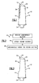
- Figure 2 illustrates an example method 40 for repairing the undesirable section 34 of the article 10. For instance, it may be desirable to repair the undesirable section 34 to restore an aerodynamic efficiency of the article 10. As can be appreciated, there may also be other reasons for the desirability of repairing the article 10.
- the example method 40 generally includes a removal step 42, an attaching step 44, and a mechanical working step 46.
- the disclosed method 40 may be used alone or in combination with additional steps to repair the article 10, such as precipitation heat treating, planishing, or other mechanical working steps.
- the removal step 42 the undesirable section 34 is at least partially removed from the article 10.
- the undesirable section 34 may be machined to either completely or partially remove the undesirable section 34.
- the attaching step 44 includes attaching a repair section to the article 10.
- the mechanical working step 46 includes mechanically working the repair section to reduce a cross-sectional area of the repair section.
- Figures 3-5 illustrate an example application of the method 40 to repair the article 10.
- Figure 3 illustrates the article 10 after the undesirable section 34 has been removed.
- the undesirable section 34 may be removed using any suitable technique, such as cutting, grinding, blasting, and chemical etching. Upon removal, there is a void 48 in the location from which the undesirable section 34 was removed.
- a repair section 50 is then attached to the article 10 in the location of the void 48.
- the repair section 50 may nominally have the same composition as the alloy of the article 10.
- the repair section includes about 50-55wt% nickel, about 17-21wt% chromium, about 0.65-1.15wt% titanium, about 0.2-0.8wt% aluminum, about 4.75-5.5wt% columbium, about 0-1wt% cobalt, about 2.8-3.3wt% molybdenum, and a balance of iron.
- the repair section 50 may be attached to the article 10 using any suitable technique.
- the repair section 50 may be attached using a welding technique.
- the repair section 50 may also be considered as a welded repair section.
- the welding technique is gas tungsten arc welding, laser powder weld deposition, plasma arc welding, micro-metal inert gas welding, or other type of welding technique.
- the repair section 50 may be formed in any suitable manner.
- the repair section 50 may be prefabricated and then attached to the article 10, or the repair section 50 may be formed by depositing a powder, wire, or other welding material on the article 10.
- the repair section 50 in this example is larger in size than the original geometry of the article 10.
- the original geometry is represented by dashed line 52.
- the repair section 50 initially includes an associated cross-sectional area 54 extending between the first side 18 and the second side 20.
- the cross-sectional area 54 is larger than cross-sectional area 56 of the original geometry of the article 10.
- the repair section 50 may be machined down to the cross-sectional area 54 after attaching the repair section 50, in preparation for the mechanical working step 46.
- the article 10 may then be placed into a die 60 to conduct the mechanical working step 46.
- the mechanical working step includes forging the article 10 at a relatively cold temperature (e.g., room temperature); however, it is to be understood that the mechanical working step 46 may ]include other types of mechanical working operations, such as planishing or other metalworking operations.
- the die 60 includes a pair of die halves 62 that define a cavity 64 that is contoured to the shape of the original article 10.
- the cavity 64 may enclose the entire article 10 (airfoil 12 and base platform 24), only the airfoil 12, only the repair section 50, or the repair section with some overlap of the airfoil 12 (e.g., to facilitate fixturing).
- the die halves 62 compress and plastically deform the repair section 50 to reduce the cross-sectional area 54 down to no less than the cross-sectional area 56 of the original geometry of the article 10.
- the die halves 62 are then opened, and the article 10 is removed. Any flash material from the repair section 50 may then be trimmed, leaving the article 10 and repair section 50 having a geometry that is substantially equal to the original geometry as illustrated in Figure 5 .
- the mechanical working step 46 may include planishing.
- the planishing may be roll planishing where the repair section 50 is rolled between rollers R to reduce the cross-sectional area 54 down to no less than the cross-sectional area 56 of the original geometry of the article 10.
- the planishing may be hammer planishing where the repair section 50 is hammered between a reciprocating hammer 57a and a planish stake 57b to reduce the cross-sectional area 54 down to no less than the cross-sectional area 56 of the original geometry of the article 10.
- the planishing may be conducted manually or using an automated or semi-automated planishing machine.
- Mechanically working the repair section 50 causes plastic deformation entirely through the cross-sectional area 56 of the repair section 50.
- the mechanical working causes dislocations within the microstructure of the alloy used to form the article 10.
- the dislocations contribute to improving the physical properties of the repair section 50, such as increasing ultimate tensile strength, fatigue strength, and hardness.
- the properties of the repair section 50 are substantially equal to or better than the properties of the original article 10 because of the dislocations.
- the degree of mechanical working that is used may also be varied, depending upon the desired properties of the repair section 50. For instance, a greater degree of mechanical working may be used to achieve a relatively greater degree of fatigue strength, or a relatively lower amount of mechanical working may be used to achieve a desired lower fatigue strength.
- the mechanical working reduces the cross-sectional area 54 to the cross-sectional area 56 by 10%-50%. In a further example, the reduction is about 30%.
- the plastic deformation of the repair section 50 is distributed entirely through the cross-sectional area 56 of the repair section 50.
- the distribution and degree of plastic deformation may be determined using scanning electron microscope electron back-scatter imaging. Such a technique is generally known in the art and need not be detailed in this disclosure.
- Figure 8 illustrates an example schematic image 68 using scanning electron microscope electron back-scatter diffraction patterns (Orientation Imaging Microscopy).
- the image 68 is a cross-section of the repair section 50 extending between the first side 18 and the second side 20 of the article 10.
- Plastic deformation is represented by regions 70 (shown as specks). As can be appreciated from the image 68, the regions 70 are distributed entirely through the cross-section between the sides 18 and 20. Plastic deformation distributed entirely through the thickness provides the entire repair section 50 with improved physical properties.
- the method 40 may also be used to achieve a desirable microstructure 80.
- the microstructure 80 includes regions of Laves phase 82 distributed within a matrix 84 of the alloy composition.
- the microstructure 80 is substantially free from, and in some examples entirely free of, orthorhombic delta phase regions of Ni 3 Cb, which is a needle-shaped phase that is known to degrade physical properties (e.g., fatigue strength).
- the disclosed method 40 may be used to avoid a solution heat treating step that typically results in the formation of the delta phase.
- an article having a repair section may be heat treated at 1750°F (954°C) or higher to homogenously solutionize elements within the alloy, and then be aged at approximately 1150-1350°F (621-732°C) to precipitation strengthen the alloy.
- the heat treating typically contributes to the formation of the delta phase.
- the solution heat treating step can be eliminated because the plastic deformation and dislocations from the mechanical working contribute to improving fatigue strength and thereby lessen the need for heat treating. Therefore, at least the heat treating step may be eliminated, although it still may be desirable to utilize the aging process to achieve a degree of precipitation strengthening.
- the method 40 may also be used in combination with additional steps to further restore the original geometry and/or performance of the article 10. For instance, various mechanical finishing steps may be used to restore the article 10.
- the article 10 may be peened, coated, vibratory finished, or otherwise processed.
Landscapes
- Engineering & Computer Science (AREA)
- Mechanical Engineering (AREA)
- Chemical & Material Sciences (AREA)
- General Engineering & Computer Science (AREA)
- Crystallography & Structural Chemistry (AREA)
- Materials Engineering (AREA)
- Metallurgy (AREA)
- Organic Chemistry (AREA)
- Turbine Rotor Nozzle Sealing (AREA)
- Structures Of Non-Positive Displacement Pumps (AREA)
- Application Of Or Painting With Fluid Materials (AREA)
Abstract
Description
- This disclosure relates to a repair method and a repaired article. More particularly, the disclosure relates to a repair method for providing a repaired article having properties that are substantially equal to or better than properties of the original article.
- In many instances, there is a desire to repair an article rather than replace the article with a new article. For instance, airfoils used as blades or vanes in a gas turbine engine are relatively expensive. Due to the expense, repairing the airfoils may be more cost efficient than replacing the airfoils with new airfoils.
- The erosion, wear, or corrosion may gradually change the original design geometry of the airfoil and degrade the aerodynamic efficiency of the airfoil. To repair the airfoil, the eroded, worn, or corroded section may be removed and replaced with a repair section to restore the aerodynamic efficiency. The repair section may be welded onto the airfoil and then machined to attain the original design geometry. Although effective, one potential drawback is that the heat from welding may negatively influence the mechanical properties of the repair section and airfoil. For instance, heat-affected regions of the repair section and airfoil may include undesirable microstructural phases that contribute to lower than desired mechanical properties.
- Therefore, there is a continuing need for new repair processes that provide repaired articles having properties that are substantially equal to or better than the original properties of the article.
- The disclosed repair method and repaired article are for providing the repaired article with physical properties that are substantially equal to or better than the physical properties of the original article.
- In one example, a method of repairing the article includes at least partially removing an undesirable section of the article, attaching a repair section to the article at a location from which the undesirable section has been removed, and mechanically working the repair section to thereby achieve a reduction in a cross-sectional area of the repair section.
- In another aspect, a method of repairing the article includes at least partially removing an undesirable section of the article, welding a repair section to the article at a location from which the undesirable section has been removed, and mechanically cold working the repair section to thereby achieve a 10%-50% reduction in a cross-sectional area of the repair section.
- The disclosed examples may be used to repair an article. For example, a repaired article may include a body extending between a first side and a second side, where the body includes a repair section having an associated thickness between the first side and the second side. The repair section includes regions of plastic deformation distributed entirely through the thickness. For example, the plastic deformation contributes to restoring fatigue strength.
- The various features and advantages of the disclosed examples will become apparent to those skilled in the art from the following detailed description. The drawings that accompany the detailed description can be briefly described as follows.
-
Figure 1 illustrates an example article for repair. -
Figure 2 illustrates an example method for repairing the article. -
Figure 3 illustrates an example implementation of a removal step of a repair method. -
Figure 4 illustrates an example implementation of an attaching step and a mechanical working step of a repair method. -
Figure 5 illustrates an example of the article after being repaired. -
Figure 6 illustrates an example mechanical working step that includes roll planishing. -
Figure 7 illustrates an example mechanical working step that includes hammer planishing. -
Figure 8 schematically illustrates an image of a repair section having regions of plastic deformation. -
Figure 9 illustrates an example microstructure that is substantially free of a delta phase. -
Figure 1 illustrates selected portions of anexample article 10 that is to be repaired. In this example, thearticle 10 is illustrated as a rotatable airfoil blade that may be used within a gas turbine engine. However, it is to be understood that thearticle 10 may alternatively be a relatively static airfoil vane. For example, airfoil blades and vanes are commonly used in a compressor and turbine sections of the engine. Alternatively, thearticle 10 may be any other type of article and is not limited to the disclosed examples. - The
article 10 may be fabricated from any suitable type of metallic alloy, such as a nickel-based alloy. The nickel-based alloy may include about 50-55wt% nickel, about 17-21wt% chromium, about 0.65-1.15wt% titanium, about 0.2-0.8wt% aluminum, about 4.75-5.5wt% columbium, about 0-1wt% cobalt, about 2.8-3.3wt% molybdenum, and a balance of iron. In some examples, the nickel-based alloy includes only the above elements. In other examples, the nickel-based alloy may include impurities that do not affect the properties of the alloy or impurities that are unmeasured or undetectable in the alloy. - The
example article 10 includes anairfoil 12 having a leadingedge 14, atrailing edge 16, afirst side 18, and asecond side 20. For example, thefirst side 18 and thesecond side 20 may correspond to a pressure side and a suction side when used within a gas turbine engine. Theairfoil 12 also extends between atip 22 and abase platform 24 that is used to mount thearticle 10 within an engine. As can be appreciated, the design of the illustrated blade may vary, and the illustrated design is not intended to be a limitation on this disclosure. - The
article 10 has been subjected to a period of use within a gas turbine engine, for example. As a result, thearticle 10 has developed anundesirable section 34. For example, theundesirable section 34 may be an eroded section, worn section, corroded section, or other type of section exhibiting blemishes from use of thearticle 10. In examples where thearticle 10 is not an engine component, there may be other causes of theundesirable section 34 that are related to the particular use of thearticle 10. - The
undesirable section 34 in this example is located at the leadingedge 14 of thearticle 10. However, in other examples, theundesirable section 34 may be located at thetrailing edge 16,tip 22,base platform 24, or other portions of thearticle 10. -
Figure 2 illustrates anexample method 40 for repairing theundesirable section 34 of thearticle 10. For instance, it may be desirable to repair theundesirable section 34 to restore an aerodynamic efficiency of thearticle 10. As can be appreciated, there may also be other reasons for the desirability of repairing thearticle 10. - The
example method 40 generally includes aremoval step 42, an attachingstep 44, and a mechanical workingstep 46. The disclosedmethod 40 may be used alone or in combination with additional steps to repair thearticle 10, such as precipitation heat treating, planishing, or other mechanical working steps. In theremoval step 42, theundesirable section 34 is at least partially removed from thearticle 10. For instance, theundesirable section 34 may be machined to either completely or partially remove theundesirable section 34. The attachingstep 44 includes attaching a repair section to thearticle 10. Finally, themechanical working step 46 includes mechanically working the repair section to reduce a cross-sectional area of the repair section. -
Figures 3-5 illustrate an example application of themethod 40 to repair thearticle 10. For instance,Figure 3 illustrates thearticle 10 after theundesirable section 34 has been removed. Theundesirable section 34 may be removed using any suitable technique, such as cutting, grinding, blasting, and chemical etching. Upon removal, there is avoid 48 in the location from which theundesirable section 34 was removed. - Referring to
Figure 4 , arepair section 50 is then attached to thearticle 10 in the location of the void 48. Therepair section 50 may nominally have the same composition as the alloy of thearticle 10. In one example, the repair section includes about 50-55wt% nickel, about 17-21wt% chromium, about 0.65-1.15wt% titanium, about 0.2-0.8wt% aluminum, about 4.75-5.5wt% columbium, about 0-1wt% cobalt, about 2.8-3.3wt% molybdenum, and a balance of iron. - The
repair section 50 may be attached to thearticle 10 using any suitable technique. For example, therepair section 50 may be attached using a welding technique. In this regard, therepair section 50 may also be considered as a welded repair section. In some examples, the welding technique is gas tungsten arc welding, laser powder weld deposition, plasma arc welding, micro-metal inert gas welding, or other type of welding technique. Additionally, therepair section 50 may be formed in any suitable manner. For example, therepair section 50 may be prefabricated and then attached to thearticle 10, or therepair section 50 may be formed by depositing a powder, wire, or other welding material on thearticle 10. - As can be appreciated, the
repair section 50 in this example is larger in size than the original geometry of thearticle 10. The original geometry is represented by dashedline 52. For instance, therepair section 50 initially includes an associatedcross-sectional area 54 extending between thefirst side 18 and thesecond side 20. Thecross-sectional area 54 is larger thancross-sectional area 56 of the original geometry of thearticle 10. In some examples, therepair section 50 may be machined down to thecross-sectional area 54 after attaching therepair section 50, in preparation for the mechanical workingstep 46. - The
article 10 may then be placed into a die 60 to conduct the mechanical workingstep 46. In this example, the mechanical working step includes forging thearticle 10 at a relatively cold temperature (e.g., room temperature); however, it is to be understood that the mechanical workingstep 46 may ]include other types of mechanical working operations, such as planishing or other metalworking operations. - The
die 60 includes a pair ofdie halves 62 that define acavity 64 that is contoured to the shape of theoriginal article 10. Thecavity 64 may enclose the entire article 10 (airfoil 12 and base platform 24), only theairfoil 12, only therepair section 50, or the repair section with some overlap of the airfoil 12 (e.g., to facilitate fixturing). The die halves 62 compress and plastically deform therepair section 50 to reduce thecross-sectional area 54 down to no less than thecross-sectional area 56 of the original geometry of thearticle 10. The die halves 62 are then opened, and thearticle 10 is removed. Any flash material from therepair section 50 may then be trimmed, leaving thearticle 10 andrepair section 50 having a geometry that is substantially equal to the original geometry as illustrated inFigure 5 . - As an alternative to forging, or in addition to forging, the mechanical working
step 46 may include planishing. As illustrated inFigure 6 , the planishing may be roll planishing where therepair section 50 is rolled between rollers R to reduce thecross-sectional area 54 down to no less than thecross-sectional area 56 of the original geometry of thearticle 10. As illustrated inFigure 7 , the planishing may be hammer planishing where therepair section 50 is hammered between areciprocating hammer 57a and aplanish stake 57b to reduce thecross-sectional area 54 down to no less than thecross-sectional area 56 of the original geometry of thearticle 10. The planishing may be conducted manually or using an automated or semi-automated planishing machine. - Mechanically working the
repair section 50 causes plastic deformation entirely through thecross-sectional area 56 of therepair section 50. For instance, the mechanical working causes dislocations within the microstructure of the alloy used to form thearticle 10. The dislocations contribute to improving the physical properties of therepair section 50, such as increasing ultimate tensile strength, fatigue strength, and hardness. For example, the properties of therepair section 50 are substantially equal to or better than the properties of theoriginal article 10 because of the dislocations. - The degree of mechanical working that is used may also be varied, depending upon the desired properties of the
repair section 50. For instance, a greater degree of mechanical working may be used to achieve a relatively greater degree of fatigue strength, or a relatively lower amount of mechanical working may be used to achieve a desired lower fatigue strength. In some examples, the mechanical working reduces thecross-sectional area 54 to thecross-sectional area 56 by 10%-50%. In a further example, the reduction is about 30%. - The plastic deformation of the
repair section 50 is distributed entirely through thecross-sectional area 56 of therepair section 50. For instance, the distribution and degree of plastic deformation may be determined using scanning electron microscope electron back-scatter imaging. Such a technique is generally known in the art and need not be detailed in this disclosure. -
Figure 8 illustrates an exampleschematic image 68 using scanning electron microscope electron back-scatter diffraction patterns (Orientation Imaging Microscopy). In this example, theimage 68 is a cross-section of therepair section 50 extending between thefirst side 18 and thesecond side 20 of thearticle 10. Plastic deformation is represented by regions 70 (shown as specks). As can be appreciated from theimage 68, theregions 70 are distributed entirely through the cross-section between thesides entire repair section 50 with improved physical properties. - Referring to
Figure 9 , themethod 40 may also be used to achieve adesirable microstructure 80. For example, themicrostructure 80 includes regions ofLaves phase 82 distributed within amatrix 84 of the alloy composition. In this example, themicrostructure 80 is substantially free from, and in some examples entirely free of, orthorhombic delta phase regions of Ni3Cb, which is a needle-shaped phase that is known to degrade physical properties (e.g., fatigue strength). For instance, the disclosedmethod 40 may be used to avoid a solution heat treating step that typically results in the formation of the delta phase. In some repair processes, an article having a repair section may be heat treated at 1750°F (954°C) or higher to homogenously solutionize elements within the alloy, and then be aged at approximately 1150-1350°F (621-732°C) to precipitation strengthen the alloy. The heat treating typically contributes to the formation of the delta phase. However, using the disclosedmethod 40, the solution heat treating step can be eliminated because the plastic deformation and dislocations from the mechanical working contribute to improving fatigue strength and thereby lessen the need for heat treating. Therefore, at least the heat treating step may be eliminated, although it still may be desirable to utilize the aging process to achieve a degree of precipitation strengthening. - The
method 40 may also be used in combination with additional steps to further restore the original geometry and/or performance of thearticle 10. For instance, various mechanical finishing steps may be used to restore thearticle 10. Thearticle 10 may be peened, coated, vibratory finished, or otherwise processed. - Although a combination of features is shown in the illustrated examples, not all of them need to be combined to realize the benefits of various embodiments of this disclosure. In other words, a system designed according to an embodiment of this disclosure will not necessarily include all of the features shown in any one of the Figures or all of the portions schematically shown in the Figures. Moreover, selected features of one example embodiment may be combined with selected features of other example embodiments.
- The preceding description is exemplary rather than limiting in nature. Variations and modifications to the disclosed examples may become apparent to those skilled in the art that do not necessarily depart from the essence of this disclosure. The scope of legal protection given to this disclosure can only be determined by studying the following claims.
Claims (15)
- A method of repairing an article (10), comprising:removing an undesirable section (34) of an article (10) comprised of a metallic alloy;attaching a repair section (50) to the article (10) at a location from which the undesirable section (34) has been removed; andmechanically working the repair section (50) to thereby achieve a reduction in a cross-sectional area (54) of the repair section (50).
- The method as recited in claim 1, comprising reducing the cross-sectional area (54) by 10%-50%, for example by 30%.
- The method as recited in claim 1 or 2, wherein mechanically working the repair section includes one or more of: forging the repair section (50) in a die, roll planishing the repair section (50) between rollers or hammer planishing the repair section (50).
- The method as recited in claim 1, 2 or 3, wherein mechanically working the repair section (50) includes plastically deforming the repair section (50) through a thickness of the repair section (50), optionally as indicated by using scanning electron microscope electron backscatter diffraction patterns.
- The method as recited in any preceding claim, comprising mechanically working the repair section (50) at a temperature below a heat treatment temperature of the metallic alloy.
- The method as recited in claim 5, further comprising aging the article (10) at an elevated temperature, after mechanically working the article (10), to precipitation-strengthen the article.
- The method as recited in any preceding claim, wherein attaching the repair section (50) to the article (10) includes welding the repair section (50) to the article (10).
- The method as recited in any preceding claim, wherein at least a portion of the article (10) includes an airfoil (12) having a leading edge (14) and a trailing edge (16), and the repair section (50) is located at the leading edge (14) of the airfoil (12).
- A method of repairing an article (10), comprising:removing an undesirable section (34) of an article (10) comprised of a metallic alloy;welding a repair section (50) to the article (10) at a location from which the undesirable section (34) has been removed; andmechanically cold working the repair section (50) at a temperature below a heat treating temperature of the metallic alloy to reduce a cross-sectional area (50) of the repair section (50) by 10%-50%.
- The method as recited in any preceding claim, further comprising forming the repair section (50) from an alloy comprising about 50-55wt% nickel, about 17-21wt% chromium, about 0.65-1.15wt% titanium, about 0.2-0.8wt% aluminum, about 4.75-5.5wt% columbium, about 0-1wt% cobalt, about 2.8-3.3wt% molybdenum, and a balance of iron.
- The method as recited in claim 9 or 10, further comprising machining the repair section (50) after mechanically cold working the repair section (50) to achieve a desired shape of the repair section (50).
- A repaired article comprising:a body extending between a first side (18) and a second side (20), the body including a repair section (50) having an associated thickness between the first side (18) and the second side (20), and the repair section (50) includes regions of plastic deformation distributed through the thickness.
- The repaired article as recited in claim 12, wherein the body is comprised of an alloy that includes about 50-55wt% nickel, about 17-21wt% chromium, about 0.65-1.15wt% titanium, about 0.2-0.8wt% aluminum, about 4.75-5.5wt% columbium, about 0-1wt% cobalt, about 2.8-3.3wt% molybdenum, and a balance of iron.
- The repaired article as recited in claim 17, wherein the repair section (50) includes a microstructure that is substantially free of orthorhombic delta phase regions of Ni3Cb.
- The repaired article as recited in any of claims 12 to 14, wherein at least a portion of the body includes an airfoil (12) having a leading edge (14) and a trailing edge (16), and wherein the repair section is, for example, located at the leading edge (14) of the airfoil (12).
Applications Claiming Priority (1)
| Application Number | Priority Date | Filing Date | Title |
|---|---|---|---|
| US12/107,849 US8539659B2 (en) | 2008-04-23 | 2008-04-23 | Method of repairing an article |
Publications (3)
| Publication Number | Publication Date |
|---|---|
| EP2111944A2 true EP2111944A2 (en) | 2009-10-28 |
| EP2111944A3 EP2111944A3 (en) | 2010-04-28 |
| EP2111944B1 EP2111944B1 (en) | 2017-05-17 |
Family
ID=40602691
Family Applications (1)
| Application Number | Title | Priority Date | Filing Date |
|---|---|---|---|
| EP09250714.4A Active EP2111944B1 (en) | 2008-04-23 | 2009-03-13 | Repair method and repaired article |
Country Status (2)
| Country | Link |
|---|---|
| US (2) | US8539659B2 (en) |
| EP (1) | EP2111944B1 (en) |
Cited By (1)
| Publication number | Priority date | Publication date | Assignee | Title |
|---|---|---|---|---|
| EP3486028A1 (en) * | 2017-11-02 | 2019-05-22 | United Technologies Corporation | Repair of components using additive manufacturing with in-situ cold working |
Families Citing this family (21)
| Publication number | Priority date | Publication date | Assignee | Title |
|---|---|---|---|---|
| JP4898720B2 (en) * | 2008-02-14 | 2012-03-21 | 三菱重工業株式会社 | Turbine blade repair method |
| US8281487B2 (en) * | 2009-01-20 | 2012-10-09 | United Technologies Corporation | Control of case wall growth during repair and method |
| US8651393B2 (en) * | 2010-03-26 | 2014-02-18 | Holland, L.P. | Repair insert for repairing metallic structure |
| US8813331B2 (en) | 2011-03-29 | 2014-08-26 | General Electric Company | Process of preparing a turbine rotor wheel, a repair wheel for a turbine rotor wheel, and a turbine rotor wheel |
| US20120279066A1 (en) * | 2011-05-06 | 2012-11-08 | United Technologies Corporation | WELDING Ti-6246 INTEGRALLY BLADED ROTOR AIRFOILS |
| DE102011080187A1 (en) * | 2011-08-01 | 2013-02-07 | Siemens Aktiengesellschaft | A method of producing a blade for a turbomachine and blade for a turbomachine |
| EP2781691A1 (en) * | 2013-03-19 | 2014-09-24 | Alstom Technology Ltd | Method for reconditioning a hot gas path part of a gas turbine |
| US10907609B2 (en) * | 2014-07-15 | 2021-02-02 | Ge Renewable Technologies | Apparatus and method for modifying a geometry of a turbine part |
| CA2857297C (en) * | 2014-07-21 | 2021-08-17 | Alstom Renewable Technologies | Apparatus and method for modifying a geometry of a turbine part |
| US9670984B2 (en) * | 2015-01-05 | 2017-06-06 | Caterpillar Inc. | Method for remanufacturing flywheel |
| EP3061556B1 (en) | 2015-02-26 | 2018-08-15 | Rolls-Royce Corporation | Method for repairing a dual walled metallic component using braze material and such component obtained |
| EP3061557B1 (en) | 2015-02-26 | 2018-04-18 | Rolls-Royce Corporation | Repair of dual walled metallic components using directed energy deposition material addition |
| US10544683B2 (en) | 2016-08-30 | 2020-01-28 | Rolls-Royce Corporation | Air-film cooled component for a gas turbine engine |
| US10689984B2 (en) | 2016-09-13 | 2020-06-23 | Rolls-Royce Corporation | Cast gas turbine engine cooling components |
| US20180073390A1 (en) | 2016-09-13 | 2018-03-15 | Rolls-Royce Corporation | Additively deposited gas turbine engine cooling component |
| US10260349B2 (en) * | 2016-10-12 | 2019-04-16 | General Electric Company | Tubine blade and related method of forming |
| US11338396B2 (en) | 2018-03-08 | 2022-05-24 | Rolls-Royce Corporation | Techniques and assemblies for joining components |
| US11090771B2 (en) | 2018-11-05 | 2021-08-17 | Rolls-Royce Corporation | Dual-walled components for a gas turbine engine |
| US11305363B2 (en) | 2019-02-11 | 2022-04-19 | Rolls-Royce Corporation | Repair of through-hole damage using braze sintered preform |
| US11692446B2 (en) | 2021-09-23 | 2023-07-04 | Rolls-Royce North American Technologies, Inc. | Airfoil with sintered powder components |
| GB2624020B (en) * | 2022-11-04 | 2025-07-02 | Gkn Aerospace Sweden Ab | IBR blade repair |
Citations (4)
| Publication number | Priority date | Publication date | Assignee | Title |
|---|---|---|---|---|
| GB1269598A (en) | 1970-10-01 | 1972-04-06 | North American Rockwell | Solid state repair method for metal articles |
| EP1734225A1 (en) | 2005-06-15 | 2006-12-20 | General Electric Company | Systematic cold working of welds |
| WO2007081924A2 (en) | 2006-01-09 | 2007-07-19 | Surface Technology Holdings, Ltd. | Method of improving the properties of a repaired component and a component improved thereby |
| US20070234772A1 (en) | 2006-04-07 | 2007-10-11 | Prevey Paul S Iii | Surface treatment apparatus and method |
Family Cites Families (20)
| Publication number | Priority date | Publication date | Assignee | Title |
|---|---|---|---|---|
| US2680286A (en) * | 1949-09-24 | 1954-06-08 | Hartford Nat Bank & Trust Co | Coining blade forging |
| GB897137A (en) | 1958-05-28 | 1962-05-23 | Gen Electric | Improvements in or relating to apparatus for shaping aerodynamic blades |
| US3676225A (en) * | 1970-06-25 | 1972-07-11 | United Aircraft Corp | Thermomechanical processing of intermediate service temperature nickel-base superalloys |
| US4156582A (en) * | 1976-12-13 | 1979-05-29 | General Electric Company | Liquid cooled gas turbine buckets |
| CA1131104A (en) | 1979-04-25 | 1982-09-07 | United States Of America (Government Of The) United States Department Of Energy | Process for treating weldments |
| US4602952A (en) * | 1985-04-23 | 1986-07-29 | Cameron Iron Works, Inc. | Process for making a composite powder metallurgical billet |
| US5111570A (en) * | 1990-08-10 | 1992-05-12 | United Technologies Corporation | Forge joining repair technique |
| US5826453A (en) * | 1996-12-05 | 1998-10-27 | Lambda Research, Inc. | Burnishing method and apparatus for providing a layer of compressive residual stress in the surface of a workpiece |
| US7150922B2 (en) * | 2000-03-13 | 2006-12-19 | General Electric Company | Beta-phase nickel aluminide overlay coatings and process therefor |
| US6339878B1 (en) * | 2000-03-27 | 2002-01-22 | United Technologies Corporation | Method of repairing an airfoil |
| US6672838B1 (en) * | 2000-07-27 | 2004-01-06 | General Electric Company | Method for making a metallic article with integral end band under compression |
| US6508000B2 (en) * | 2001-02-08 | 2003-01-21 | Siemens Westinghouse Power Corporation | Transient liquid phase bonding repair for advanced turbine blades and vanes |
| US6536110B2 (en) * | 2001-04-17 | 2003-03-25 | United Technologies Corporation | Integrally bladed rotor airfoil fabrication and repair techniques |
| US6575702B2 (en) * | 2001-10-22 | 2003-06-10 | General Electric Company | Airfoils with improved strength and manufacture and repair thereof |
| CN100406190C (en) * | 2001-11-02 | 2008-07-30 | 波音公司 | Apparatus and method for forming a weld joint having a distribution of residual compressive stress |
| DE10319494A1 (en) * | 2003-04-30 | 2004-11-18 | Mtu Aero Engines Gmbh | Process for repairing and / or modifying components of a gas turbine |
| US7165712B2 (en) * | 2003-10-23 | 2007-01-23 | Siemens Power Generation, Inc. | Transient liquid phase bonding to cold-worked surfaces |
| US20050091847A1 (en) | 2003-10-31 | 2005-05-05 | Beneteau Douglas P. | Method for repairing gas turbine compressor rotor blades |
| US20060168808A1 (en) * | 2005-02-03 | 2006-08-03 | United Technologies Corporation | Plasma ARC weld repair of IN100 material |
| DE502006002572D1 (en) * | 2006-01-24 | 2009-02-26 | Siemens Ag | Component repair procedures |
-
2008
- 2008-04-23 US US12/107,849 patent/US8539659B2/en active Active
-
2009
- 2009-03-13 EP EP09250714.4A patent/EP2111944B1/en active Active
-
2013
- 2013-08-22 US US13/972,966 patent/US9885240B2/en active Active
Patent Citations (4)
| Publication number | Priority date | Publication date | Assignee | Title |
|---|---|---|---|---|
| GB1269598A (en) | 1970-10-01 | 1972-04-06 | North American Rockwell | Solid state repair method for metal articles |
| EP1734225A1 (en) | 2005-06-15 | 2006-12-20 | General Electric Company | Systematic cold working of welds |
| WO2007081924A2 (en) | 2006-01-09 | 2007-07-19 | Surface Technology Holdings, Ltd. | Method of improving the properties of a repaired component and a component improved thereby |
| US20070234772A1 (en) | 2006-04-07 | 2007-10-11 | Prevey Paul S Iii | Surface treatment apparatus and method |
Cited By (1)
| Publication number | Priority date | Publication date | Assignee | Title |
|---|---|---|---|---|
| EP3486028A1 (en) * | 2017-11-02 | 2019-05-22 | United Technologies Corporation | Repair of components using additive manufacturing with in-situ cold working |
Also Published As
| Publication number | Publication date |
|---|---|
| US20130343901A1 (en) | 2013-12-26 |
| EP2111944A3 (en) | 2010-04-28 |
| EP2111944B1 (en) | 2017-05-17 |
| US8539659B2 (en) | 2013-09-24 |
| US9885240B2 (en) | 2018-02-06 |
| US20090269208A1 (en) | 2009-10-29 |
Similar Documents
| Publication | Publication Date | Title |
|---|---|---|
| EP2111944B1 (en) | Repair method and repaired article | |
| CN113454255B (en) | Ni-based superalloy and method for producing Ni-based superalloy | |
| CN106563929B (en) | Repair and manufacture the method and turbine engine components of turbine engine components | |
| US5351395A (en) | Process for producing turbine bucket with water droplet erosion protection | |
| EP1602442B1 (en) | Methods for repairing gas turbine engine components | |
| JP6011098B2 (en) | Manufacturing method of engine exhaust valve for large ship | |
| CN1757792A (en) | Erosion and wear resistant protective structures for turbine components | |
| EP3901297A1 (en) | Nickel-based alloy repaired member and method for manufacturing same | |
| EP2722407A2 (en) | Precipitation hardening martensitic stainless steel and long blade for steam turbine using the same | |
| JP2006291344A (en) | Ni-based alloy member and manufacturing method thereof, turbine engine component, welding material and manufacturing method thereof | |
| EP2298489A1 (en) | Superalloy composition and method of forming a turbine engine component | |
| CN109290569B (en) | Method for manufacturing repair parts by additive material | |
| JP6120200B2 (en) | Ni-base superalloy and turbine disk using the same | |
| JPH09192880A (en) | Method for manufacturing blade of αβ titanium having metastable β titanium insert and blade manufactured by the method | |
| US20090119920A1 (en) | Method of producing a component | |
| US20100202889A1 (en) | Method for producing a lightweight turbine blade | |
| CA2735302A1 (en) | Blade and method of repair and manufacturing the same | |
| EP2774716A2 (en) | Method of producing a hollow airfoil | |
| JP6748951B2 (en) | Method for producing Ni-base superheat-resistant alloy and Ni-base superheat-resistant alloy | |
| US20090211921A1 (en) | Procedure for the production and application of a protective layer | |
| US20040216813A1 (en) | Method for restoring the microstructure of a textured article and for refurbishing a gas turbine blade or vane | |
| JP6039355B2 (en) | Titanium aluminide construction method and product having titanium aluminide surface | |
| US6300588B1 (en) | Manufacture of repair material and articles repaired with the material | |
| US20060144477A1 (en) | Method for the production of a part having improved weldability and/or mechanical processability from an alloy | |
| WO2019099000A1 (en) | Method of repairing gamma prime strengthened superalloys |
Legal Events
| Date | Code | Title | Description |
|---|---|---|---|
| PUAI | Public reference made under article 153(3) epc to a published international application that has entered the european phase |
Free format text: ORIGINAL CODE: 0009012 |
|
| AK | Designated contracting states |
Kind code of ref document: A2 Designated state(s): AT BE BG CH CY CZ DE DK EE ES FI FR GB GR HR HU IE IS IT LI LT LU LV MC MK MT NL NO PL PT RO SE SI SK TR |
|
| AX | Request for extension of the european patent |
Extension state: AL BA RS |
|
| PUAL | Search report despatched |
Free format text: ORIGINAL CODE: 0009013 |
|
| AK | Designated contracting states |
Kind code of ref document: A3 Designated state(s): AT BE BG CH CY CZ DE DK EE ES FI FR GB GR HR HU IE IS IT LI LT LU LV MC MK MT NL NO PL PT RO SE SI SK TR |
|
| AX | Request for extension of the european patent |
Extension state: AL BA RS |
|
| RIC1 | Information provided on ipc code assigned before grant |
Ipc: C21D 7/08 20060101ALN20090514BHEP Ipc: B23P 9/04 20060101ALN20090514BHEP Ipc: F01D 5/00 20060101ALI20100325BHEP Ipc: B23P 9/02 20060101ALN20090514BHEP Ipc: F01D 5/28 20060101ALI20100325BHEP Ipc: B23P 6/00 20060101AFI20090514BHEP |
|
| 17P | Request for examination filed |
Effective date: 20100702 |
|
| 17Q | First examination report despatched |
Effective date: 20100806 |
|
| AKX | Designation fees paid |
Designated state(s): DE GB |
|
| GRAP | Despatch of communication of intention to grant a patent |
Free format text: ORIGINAL CODE: EPIDOSNIGR1 |
|
| RIC1 | Information provided on ipc code assigned before grant |
Ipc: F01D 5/28 20060101ALI20160913BHEP Ipc: B23P 9/02 20060101ALN20160913BHEP Ipc: B21K 3/04 20060101ALN20160913BHEP Ipc: B24B 39/00 20060101ALN20160913BHEP Ipc: B24B 39/06 20060101ALN20160913BHEP Ipc: B23P 9/04 20060101ALN20160913BHEP Ipc: F01D 5/00 20060101ALI20160913BHEP Ipc: C21D 7/08 20060101ALN20160913BHEP Ipc: B23P 6/00 20060101AFI20160913BHEP |
|
| RAP1 | Party data changed (applicant data changed or rights of an application transferred) |
Owner name: UNITED TECHNOLOGIES CORPORATION |
|
| INTG | Intention to grant announced |
Effective date: 20161018 |
|
| GRAS | Grant fee paid |
Free format text: ORIGINAL CODE: EPIDOSNIGR3 |
|
| GRAJ | Information related to disapproval of communication of intention to grant by the applicant or resumption of examination proceedings by the epo deleted |
Free format text: ORIGINAL CODE: EPIDOSDIGR1 |
|
| GRAL | Information related to payment of fee for publishing/printing deleted |
Free format text: ORIGINAL CODE: EPIDOSDIGR3 |
|
| GRAR | Information related to intention to grant a patent recorded |
Free format text: ORIGINAL CODE: EPIDOSNIGR71 |
|
| INTC | Intention to grant announced (deleted) | ||
| GRAA | (expected) grant |
Free format text: ORIGINAL CODE: 0009210 |
|
| RIC1 | Information provided on ipc code assigned before grant |
Ipc: B24B 39/06 20060101ALN20170313BHEP Ipc: F01D 5/28 20060101ALI20170313BHEP Ipc: B23P 9/02 20060101ALN20170313BHEP Ipc: B23P 9/04 20060101ALN20170313BHEP Ipc: B23P 6/00 20060101AFI20170313BHEP Ipc: B24B 39/00 20060101ALN20170313BHEP Ipc: C21D 7/08 20060101ALN20170313BHEP Ipc: B21K 3/04 20060101ALN20170313BHEP Ipc: F01D 5/00 20060101ALI20170313BHEP |
|
| AK | Designated contracting states |
Kind code of ref document: B1 Designated state(s): DE GB |
|
| INTG | Intention to grant announced |
Effective date: 20170411 |
|
| REG | Reference to a national code |
Ref country code: GB Ref legal event code: FG4D |
|
| REG | Reference to a national code |
Ref country code: DE Ref legal event code: R096 Ref document number: 602009046108 Country of ref document: DE |
|
| REG | Reference to a national code |
Ref country code: DE Ref legal event code: R082 Ref document number: 602009046108 Country of ref document: DE Representative=s name: SCHMITT-NILSON SCHRAUD WAIBEL WOHLFROM PATENTA, DE |
|
| REG | Reference to a national code |
Ref country code: DE Ref legal event code: R097 Ref document number: 602009046108 Country of ref document: DE |
|
| PLBE | No opposition filed within time limit |
Free format text: ORIGINAL CODE: 0009261 |
|
| STAA | Information on the status of an ep patent application or granted ep patent |
Free format text: STATUS: NO OPPOSITION FILED WITHIN TIME LIMIT |
|
| 26N | No opposition filed |
Effective date: 20180220 |
|
| REG | Reference to a national code |
Ref country code: DE Ref legal event code: R081 Ref document number: 602009046108 Country of ref document: DE Owner name: RAYTHEON TECHNOLOGIES CORPORATION (N.D.GES.D.S, US Free format text: FORMER OWNER: UNITED TECHNOLOGIES CORPORATION, FARMINGTON, CONN., US Ref country code: DE Ref legal event code: R081 Ref document number: 602009046108 Country of ref document: DE Owner name: RTX CORPORATION (N.D.GES.D. STAATES DELAWARE),, US Free format text: FORMER OWNER: UNITED TECHNOLOGIES CORPORATION, FARMINGTON, CONN., US |
|
| P01 | Opt-out of the competence of the unified patent court (upc) registered |
Effective date: 20230519 |
|
| REG | Reference to a national code |
Ref country code: DE Ref legal event code: R081 Ref document number: 602009046108 Country of ref document: DE Owner name: RTX CORPORATION (N.D.GES.D. STAATES DELAWARE),, US Free format text: FORMER OWNER: RAYTHEON TECHNOLOGIES CORPORATION (N.D.GES.D.STAATES DELAWARE), ARLINGTON, VA, US |
|
| PGFP | Annual fee paid to national office [announced via postgrant information from national office to epo] |
Ref country code: GB Payment date: 20260220 Year of fee payment: 18 |
|
| PGFP | Annual fee paid to national office [announced via postgrant information from national office to epo] |
Ref country code: DE Payment date: 20260219 Year of fee payment: 18 |