EP2111894A1 - Herzstimulator mit Stimulationserfolgskontrolle - Google Patents
Herzstimulator mit Stimulationserfolgskontrolle Download PDFInfo
- Publication number
- EP2111894A1 EP2111894A1 EP09156055A EP09156055A EP2111894A1 EP 2111894 A1 EP2111894 A1 EP 2111894A1 EP 09156055 A EP09156055 A EP 09156055A EP 09156055 A EP09156055 A EP 09156055A EP 2111894 A1 EP2111894 A1 EP 2111894A1
- Authority
- EP
- European Patent Office
- Prior art keywords
- stimulation
- ventricular
- heart stimulator
- unit
- success
- Prior art date
- Legal status (The legal status is an assumption and is not a legal conclusion. Google has not performed a legal analysis and makes no representation as to the accuracy of the status listed.)
- Granted
Links
- 230000000638 stimulation Effects 0.000 title claims abstract description 157
- 230000002861 ventricular Effects 0.000 claims abstract description 76
- 238000001514 detection method Methods 0.000 claims abstract description 33
- 230000000747 cardiac effect Effects 0.000 claims description 13
- 238000011156 evaluation Methods 0.000 claims description 13
- 230000005284 excitation Effects 0.000 claims description 8
- 230000004044 response Effects 0.000 claims description 3
- 230000001746 atrial effect Effects 0.000 description 19
- 230000035939 shock Effects 0.000 description 18
- 210000004165 myocardium Anatomy 0.000 description 14
- 230000008602 contraction Effects 0.000 description 12
- 210000005241 right ventricle Anatomy 0.000 description 10
- 210000001519 tissue Anatomy 0.000 description 7
- 238000005259 measurement Methods 0.000 description 5
- 210000003748 coronary sinus Anatomy 0.000 description 4
- 210000005240 left ventricle Anatomy 0.000 description 4
- 210000005245 right atrium Anatomy 0.000 description 4
- 206010003671 Atrioventricular Block Diseases 0.000 description 3
- 238000005265 energy consumption Methods 0.000 description 3
- 239000007943 implant Substances 0.000 description 3
- 238000000034 method Methods 0.000 description 3
- 230000033764 rhythmic process Effects 0.000 description 3
- 239000000523 sample Substances 0.000 description 3
- 238000012360 testing method Methods 0.000 description 3
- 230000006870 function Effects 0.000 description 2
- 210000005003 heart tissue Anatomy 0.000 description 2
- 230000028161 membrane depolarization Effects 0.000 description 2
- 238000012544 monitoring process Methods 0.000 description 2
- 239000000243 solution Substances 0.000 description 2
- 241001295925 Gegenes Species 0.000 description 1
- 230000006978 adaptation Effects 0.000 description 1
- 210000004413 cardiac myocyte Anatomy 0.000 description 1
- 230000015556 catabolic process Effects 0.000 description 1
- 230000002999 depolarising effect Effects 0.000 description 1
- 238000010586 diagram Methods 0.000 description 1
- 230000000694 effects Effects 0.000 description 1
- 239000002184 metal Substances 0.000 description 1
- 210000003205 muscle Anatomy 0.000 description 1
- 230000002107 myocardial effect Effects 0.000 description 1
- 230000007935 neutral effect Effects 0.000 description 1
- 230000008447 perception Effects 0.000 description 1
- 230000010287 polarization Effects 0.000 description 1
- 230000002035 prolonged effect Effects 0.000 description 1
- 230000002123 temporal effect Effects 0.000 description 1
- 230000001960 triggered effect Effects 0.000 description 1
- 210000003462 vein Anatomy 0.000 description 1
- 210000002620 vena cava superior Anatomy 0.000 description 1
Images


Classifications
-
- A—HUMAN NECESSITIES
- A61—MEDICAL OR VETERINARY SCIENCE; HYGIENE
- A61N—ELECTROTHERAPY; MAGNETOTHERAPY; RADIATION THERAPY; ULTRASOUND THERAPY
- A61N1/00—Electrotherapy; Circuits therefor
- A61N1/18—Applying electric currents by contact electrodes
- A61N1/32—Applying electric currents by contact electrodes alternating or intermittent currents
- A61N1/36—Applying electric currents by contact electrodes alternating or intermittent currents for stimulation
- A61N1/362—Heart stimulators
- A61N1/37—Monitoring; Protecting
- A61N1/371—Capture, i.e. successful stimulation
-
- A—HUMAN NECESSITIES
- A61—MEDICAL OR VETERINARY SCIENCE; HYGIENE
- A61N—ELECTROTHERAPY; MAGNETOTHERAPY; RADIATION THERAPY; ULTRASOUND THERAPY
- A61N1/00—Electrotherapy; Circuits therefor
- A61N1/18—Applying electric currents by contact electrodes
- A61N1/32—Applying electric currents by contact electrodes alternating or intermittent currents
- A61N1/36—Applying electric currents by contact electrodes alternating or intermittent currents for stimulation
- A61N1/362—Heart stimulators
- A61N1/3627—Heart stimulators for treating a mechanical deficiency of the heart, e.g. congestive heart failure or cardiomyopathy
-
- A—HUMAN NECESSITIES
- A61—MEDICAL OR VETERINARY SCIENCE; HYGIENE
- A61N—ELECTROTHERAPY; MAGNETOTHERAPY; RADIATION THERAPY; ULTRASOUND THERAPY
- A61N1/00—Electrotherapy; Circuits therefor
- A61N1/18—Applying electric currents by contact electrodes
- A61N1/32—Applying electric currents by contact electrodes alternating or intermittent currents
- A61N1/36—Applying electric currents by contact electrodes alternating or intermittent currents for stimulation
- A61N1/362—Heart stimulators
- A61N1/365—Heart stimulators controlled by a physiological parameter, e.g. heart potential
- A61N1/368—Heart stimulators controlled by a physiological parameter, e.g. heart potential comprising more than one electrode co-operating with different heart regions
- A61N1/3684—Heart stimulators controlled by a physiological parameter, e.g. heart potential comprising more than one electrode co-operating with different heart regions for stimulating the heart at multiple sites of the ventricle or the atrium
- A61N1/36843—Bi-ventricular stimulation
-
- A—HUMAN NECESSITIES
- A61—MEDICAL OR VETERINARY SCIENCE; HYGIENE
- A61N—ELECTROTHERAPY; MAGNETOTHERAPY; RADIATION THERAPY; ULTRASOUND THERAPY
- A61N1/00—Electrotherapy; Circuits therefor
- A61N1/18—Applying electric currents by contact electrodes
- A61N1/32—Applying electric currents by contact electrodes alternating or intermittent currents
- A61N1/38—Applying electric currents by contact electrodes alternating or intermittent currents for producing shock effects
- A61N1/39—Heart defibrillators
- A61N1/3956—Implantable devices for applying electric shocks to the heart, e.g. for cardioversion
- A61N1/3962—Implantable devices for applying electric shocks to the heart, e.g. for cardioversion in combination with another heart therapy
- A61N1/39622—Pacing therapy
-
- A—HUMAN NECESSITIES
- A61—MEDICAL OR VETERINARY SCIENCE; HYGIENE
- A61N—ELECTROTHERAPY; MAGNETOTHERAPY; RADIATION THERAPY; ULTRASOUND THERAPY
- A61N1/00—Electrotherapy; Circuits therefor
- A61N1/18—Applying electric currents by contact electrodes
- A61N1/32—Applying electric currents by contact electrodes alternating or intermittent currents
- A61N1/36—Applying electric currents by contact electrodes alternating or intermittent currents for stimulation
- A61N1/362—Heart stimulators
- A61N1/365—Heart stimulators controlled by a physiological parameter, e.g. heart potential
- A61N1/368—Heart stimulators controlled by a physiological parameter, e.g. heart potential comprising more than one electrode co-operating with different heart regions
- A61N1/3684—Heart stimulators controlled by a physiological parameter, e.g. heart potential comprising more than one electrode co-operating with different heart regions for stimulating the heart at multiple sites of the ventricle or the atrium
-
- A—HUMAN NECESSITIES
- A61—MEDICAL OR VETERINARY SCIENCE; HYGIENE
- A61N—ELECTROTHERAPY; MAGNETOTHERAPY; RADIATION THERAPY; ULTRASOUND THERAPY
- A61N1/00—Electrotherapy; Circuits therefor
- A61N1/18—Applying electric currents by contact electrodes
- A61N1/32—Applying electric currents by contact electrodes alternating or intermittent currents
- A61N1/36—Applying electric currents by contact electrodes alternating or intermittent currents for stimulation
- A61N1/362—Heart stimulators
- A61N1/365—Heart stimulators controlled by a physiological parameter, e.g. heart potential
- A61N1/368—Heart stimulators controlled by a physiological parameter, e.g. heart potential comprising more than one electrode co-operating with different heart regions
- A61N1/3684—Heart stimulators controlled by a physiological parameter, e.g. heart potential comprising more than one electrode co-operating with different heart regions for stimulating the heart at multiple sites of the ventricle or the atrium
- A61N1/36842—Multi-site stimulation in the same chamber
Definitions
- the invention relates to a heart stimulator with stimulation success control, d. H. a heart stimulator, such as an implantable cardiac pacemaker or an implantable cardioverter defibrillator (ICD), which is capable of detecting the effectiveness of a stimulation pulse delivered to a heart.
- a heart stimulator such as an implantable cardiac pacemaker or an implantable cardioverter defibrillator (ICD), which is capable of detecting the effectiveness of a stimulation pulse delivered to a heart.
- ICD implantable cardioverter defibrillator
- Cardiac stimulators of the aforementioned type are already known in particular as implantable cardiac pacemakers.
- Such pacemakers are usually connected in the implanted and functional state via an electrode line of the aforementioned type with an electrode disposed in the heart and designed to deliver via the electrode electrical stimulation pulses to the heart - or more precisely to individual chambers of a heart.
- These stimulation impulses serve to excite the heart tissue (myocardium) of the respective chamber and, depending on the type of pacemaker, are delivered, in particular, when the heart does not contract naturally at the right time. A contraction is then caused by an electrical impulse delivered to the myocardium.
- This electrical pulse when adequately sized, has the effect of locally depolarizing the myocardial tissue and correspondingly contracting. The depolarization and contraction of the heart muscle tissue is to extend over the entire stimulated heart muscle and thus lead to the desired contraction of the corresponding ventricle.
- the corresponding electrical stimulation pulse must have a stimulation intensity that is above a respective stimulation threshold of the heart muscle tissue.
- the threshold is a measure of the minimum stimulation intensity, which is sufficient to cause a depolarization of the myocardium and thus a contraction of a respective chamber of the heart.
- the stimulus threshold depends on various factors and may also change over time.
- This energy is taken regularly from a battery of the pacemaker, which expires over time. When this battery is depleted, an implanted pacemaker (in one operation) must be replaced with a new pacemaker. A longest possible service life of the pacemaker and thus the longest possible battery life is therefore desirable.
- the energy for a stimulation pulse should also be as small as possible, but sufficient to stimulate only the myocardium, but not surrounding muscle tissue.
- the stimulation intensity of a stimulation pulse must be sufficient to trigger a contraction of the heart muscle tissue.
- a higher intensity of stimulation is associated with a greater energy consumption with otherwise unchanged variables.
- the stimulation intensity depends on the one hand on the duration of a stimulation pulse and on the other hand on the strength of a stimulation pulse.
- the strength of a stimulation pulse in turn depends on the electrical voltage with which a stimulation pulse is delivered to the heart muscle tissue. Therefore, a higher stimulation intensity regularly leads to a higher energy consumption.
- stimulation pulses are given regularly, which cost more energy in energy terms, than would be required minimal.
- the stimulation success control can be performed after each delivery of a stimulation pulse (beat-to-beat), in order to achieve a stronger one in the case of an ineffective stimulus (Automatic Capture Control ACC).
- the stimulation success control is carried out as part of an automatic threshold test (ATT), in which targeted stimulation pulses of different intensity are triggered in order to determine from which intensity a stimulation pulse is effective and thus to determine the respective stimulation threshold.
- ATT automatic threshold test
- the heart stimulator can then control its further behavior and z. For example, trigger the delivery of an efficient stimulation pulse after inefficient stimulation and in the absence of intrinsic conduction, increase the pulse intensity upon inefficient stimulation, and / or maintain or reduce the pulse intensity upon effective stimulation.
- the implantable cardiac stimulator has a far field electrogram detection unit and a stimulation success detection unit, of which the far field electrogram detection unit has a first input connected to the right ventricular defibrillation electrode terminal and a second input connected to the electroconductive housing.
- the far-field electrogram detection unit is designed to determine a far-field electrocardiogram on the basis of the electrical potentials present at the two inputs during operation and to output it to the stimulation success detection unit.
- the stimulation success detection unit has an electrogram input and a signal input and is configured to receive via the electrogram input a far field electrogram generated by the far field electrogram detection unit and to receive via the signal input a stimulation signal indicative of a chamber stimulation pulse generated and delivered by the chamber stimulation unit and a respective one of a delivery Evaluate chamber stimulation pulse immediately following section of a received far field electrogram to see whether it represents an effective or an ineffective ventricular stimulation.
- the heart stimulator (or, more precisely, its stimulation control unit) can be designed to automatically adjust the stimulation energy in the sine of an automatic threshold test (ATT) based on the measured stimulation threshold for a duration until the next test, ie not the beat to beat, perform.
- ATT automatic threshold test
- the heart stimulator or its stimulation control unit may be designed to carry out a beat-to-beat adaptation of the stimulation pulse intensity in the sense of an automatic capture control (ACC) on the basis of the measured stimulation threshold.
- ACC automatic capture control
- the heart stimulator is designed to trigger the most effective possible stimulus in the event of the stimulus threshold being undershot (that is to say when a lack of stimulation success is detected).
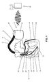
- FIG. 12 shows an implantable cardiac stimulator 10 in the form of a tri-cardiac pacemaker / cardioverter / defibrillator with electrode leads 12, 14 and 16 connected thereto in connection with a heart 18.
- an external device 100 is shown in the vicinity of the implantable cardiac stimulator 10.
- the electrode lines 12, 14 and 16 are electrically connected via known standardized plug connections with contact sockets in a header (connection housing) 20 of the heart stimulator 10.
- the electrode lines 12, 14 and 16 are also connected to electronic components inside a hermetically sealed metal housing 22 of the heart stimulator 10. These components are shown schematically in more detail below and determine the operation of the heart stimulator 10 according to the invention.
- the electrode lead 12 is a right atrial electrode lead and has at its distal end an atrial tip electrode RA Tip 24 and, a short distance away, an atrial ring electrode RA ring 26, both of which are placed in the right atrium 28 of the heart 18.
- the electrode line 14 is a right ventricular electrode lead and has at its distal end a right ventricular tip electrode RV tip 30 and in the immediate vicinity a right ventricular ring electrode RV ring 32. Both electrodes are arranged in the apex of the right ventricle 34 of the heart 18.
- the right ventricular electrode lead 14 still carries a right ventricular shock coil RV shock 36 as a large-area electrode for delivery of defibrillation shocks.
- RV shock 36 As a large-area electrode for delivery of defibrillation shocks.
- Another shock coil 38 is located in the Vena Cava Superior and is therefore also referred to below as the SVC shock electrode.
- the electrode line 16 is a left ventricular electrode lead, at the distal end of which a left ventricular tip electrode LV tip 40 and in the vicinity thereof a left ventricular ring electrode LV ring 42 are arranged.
- the left ventricular electrode line 16 carries an unspecified, but in FIG. 2
- the left ventricular electrode lead 16 is guided from the right atrium 28 of the heart 18 via the coronary sinus into a lateral vein branching from the coronary sinus and is therefore also referred to as coronary sinus lead or CS lead.
- the housing 22 of the heart stimulator 10 is at least partially conductive and itself forms a large-area electrode for receiving far-field potentials of the myocardium.
- FIG. 2 the main components of the heart stimulator 10 are shown.
- the shock electrodes 36 and 38 are each connected to a right ventricular shock pulse generator 50 and SVC shock generator 52, respectively. Both shock generators 50 and 52 are connected to a pacing control unit 54 that drives the two shock pulse generators 50 and 52 as needed to generate and deliver a defibrillation shock.
- connection for the right-ventricular tip electrode RV tip and the connection for the right-ventricular ring electrode RV ring are each connected both to a right-ventricular stimulation unit 56 and to a right-ventricular sensing unit 58. Both the right ventricular pacing unit 56 and the right ventricular sensing unit 58 are each connected to the pacing control unit 54.
- the right-ventricular stimulation unit 56 is designed to generate a right-ventricular stimulation pulse in response to a control signal of the stimulation control unit 54, and subsequently to deliver the right-ventricular tip electrode RV tip for the right-ventricular ring electrode RV ring.
- the housing 22 of the heart stimulator 10 forms a neutral electrode and the right ventricular stimulation unit 56 is connected to the connection for the right ventricular ring electrode RV Tip and the housing 22 as another electrode for delivering a stimulation pulse.
- a right ventricular stimulation pulse differs from a defibrillation shock in that the stimulation pulse has a much lower pulse strength so that it does not excite the full heart tissue (myocardium) of a ventricle like a defibrillation shock at one go, but only the heart muscle cells in the immediate vicinity of the right ventricular tip electrode RV Tip 30. This excitation then propagates through natural conduction across the entire right ventricle 34, thus providing a stimulated contraction of the right ventricle 34.
- the right ventricular sensing unit 58 is designed to first amplify and filter electrical potentials present at the connection for the right-ventricular ring electrode RV ring and the right-ventricular tip electrode RV Tip by means of an input amplifier. Furthermore, the right-ventricular sensing unit 58 is designed to evaluate the course of the electrical signals applied to its inputs in such a way that the right-ventricular sensing unit 58 automatically generates a natural (intrinsic), ie. H. automatic contraction of the right ventricle 34 detected. This can be done, for example, by comparing the course of the signal present at the inputs of the right-ventricular sensing unit 58 with a threshold value.
- the largest amplitude of the so-called R-wave signal is indicative of a natural contraction of the right ventricle 34 that can be detected by thresholding.
- the right ventricular sensing unit 58 then outputs a corresponding output signal indicative of natural contraction of the right ventricle 34 to the pacing control unit 54.
- connection for the right atrial tip electrode RA Tip and the connection for the right atrial ring electrode RA ring are connected both to a right atrial stimulation unit 60 and to a right atrial sensing unit 62, each of which in turn is connected to the stimulation control unit 54.
- the right atrial stimulation unit 60 is designed to generate stimulation pulses whose strength is sufficient to excite the right atrial myocardium.
- the right-atrial stimulation pulses may have a different pulse strength than the right-ventricular stimulation pulses.
- the right-atrial sensing unit 62 is designed to detect a so-called P-wave from the profile of the differential signal applied to its inputs, which characterizes a natural (intrinsic) contraction of the right atrium 28. If the right atrial sensing unit 62 detects a corresponding P-wave, it generates an output signal and passes it on to the stimulation control unit 54, which identifies a natural contraction of the right atrium 28.
- left ventricle tip LV terminal LV Tip and the left ventricular ring LV ring terminal LV are also connected to a left ventricular pacing unit 64 and a left ventricular sensing unit 66.
- the left ventricular pacing unit 64 and the left ventricular sensing unit 66 are also connected to the pacing control unit 54. Both work similar to the previously described stimulation units 56 and 60 and sensing units 58 and 62.
- the heart stimulator 10 is capable of detecting ECG signals from all probes.
- the ECG is derived from the terminal RV coil against the housing 22 of the implant and thus produces a far-field signal (HV
- the two leads of the atrial probe formed by the right atrial electrode lead 12 and the LV lead formed by the left ventricular electrode lead 16 are bipolar leads and represent a near field signal.
- the right ventricular lead does not necessarily have to have a stimulation lead for the present invention.
- Perception device d. H. the right ventricular tip electrode RV tip 30 and the right ventricular ring electrode RV ring 32 and the shock coil 38 in the superior vena cava can also be omitted in alternative embodiments of the invention.
- the control unit 54 has a far field electrogram detection unit 90, which is connected on the one hand to the housing 22 of the heart stimulator 10 and on the other hand to the connection RV coil for the right ventricular defibrillation electrode 36.
- the far field electrogram detection unit 90 is designed to determine a far field electrocardiogram on the basis of the electrical potentials present at the two inputs during operation. It has an output which is connected to an electrogram input of a stimulation success detection unit 92 and serves to transmit the respective far field electrocardiogram to the stimulation success detection unit 92.
- the stimulation success detection unit 92 also has a signal input which is connected to a stimulation control unit 94 of the control unit 54 and via which the stimulation success detection unit 92 receives signals each indicating a ventricular stimulation pulse generated and delivered by the ventricular stimulation unit.
- the stimulation success detection unit 92 is designed to evaluate a section of a received far-field electrogram received in each case directly following the delivery of a ventricular stimulation pulse, as to whether it represents an effective or an ineffective ventricular stimulation.
- the pacing control unit 94 is connected to the right ventricular pacing unit 56 and the left ventricular pacing unit and configured to drive it as needed to generate and deliver stimulation pulses of adjusted intensity. Further, the stimulation control unit 94 is able to adjust the intensity of the stimulation pulses in response to each determined by the stimulation success detection unit stimulation success and if necessary to adjust the stimulation pulse intensity by adjusting the duration and / or the strength (amplitude) of a stimulation pulse.
- the elements shown in the block diagram contribute to the realization of a measurement function for a left ventricular stimulation according to the invention.
- the right atrial pacing unit and the right atrial sensing unit form a right atrial channel and serve to synchronize the delivery of left ventricular pacing pulses with the patient's atrial activity. A version without this atrial canal is in principle also possible.
- the left ventricular stimulation unit allows the delivery of pacing pulses to the left ventricle via a left ventricular lead 16 routed via the coronary sinus.
- the pulse parameters such as the stimulation amplitude and the pulse duration are predetermined by the stimulation unit.
- the ECG signal which is derived from the right ventricular electrode lead against the housing of the implant, is amplified by means of an ECG amplifier block as part of the far-field electrogram detection unit 90 and filtered in a suitable broadband.
- the stimulation control unit evaluates the electrogram signal thus obtained and determines whether or not stimulus delivered via the left ventricular electrode line 16 was efficient.
- FIG. 3 A possible procedure for determining the efficiency of ventricular pacing is explained. In principle, it does not matter whether a stimulation pulse is delivered in the left or in the right ventricle. First, the determination of the prevailing rhythm or stimulation mode. With its own sinus rhythm, the atrial stimulation pulses of the heart stimulator are suppressed; in the absence of sinus rhythm, on the other hand, atrial stimulation occurs.
- the ventricle will not be stimulated; in case of AV block, the ventricle will be paced.
- a pattern of the far-field electrocardiogram present during safe ventricular stimulation is recorded. Then, for each subsequent ventricular pacing, the efficiency can be checked by making it as simple as possible to compare with the previously acquired pattern. In the case of inefficient stimulation, either a complete breakdown of the ventricular excitation or a temporal shift occurs. If complete failure is detected (if there is an AV block), pacing will occur with a safe pacing amplitude and a correspondingly prolonged AV time.
Landscapes
- Health & Medical Sciences (AREA)
- Cardiology (AREA)
- Heart & Thoracic Surgery (AREA)
- Life Sciences & Earth Sciences (AREA)
- Engineering & Computer Science (AREA)
- Biomedical Technology (AREA)
- Nuclear Medicine, Radiotherapy & Molecular Imaging (AREA)
- Radiology & Medical Imaging (AREA)
- Animal Behavior & Ethology (AREA)
- General Health & Medical Sciences (AREA)
- Public Health (AREA)
- Veterinary Medicine (AREA)
- Hospice & Palliative Care (AREA)
- Biophysics (AREA)
- Physiology (AREA)
- Electrotherapy Devices (AREA)
Abstract
Description
- Die Erfindung betrifft einen Herzstimulator mit Stimulationserfolgskontrolle, d. h. einen Herzstimulator, wie einen implantierbaren Herzschrittmacher oder einen implantierbaren Kardioverter/Defibrillator (ICD), der selbsttätig in der Lage ist, die Wirksamkeit eines an ein Herz abgegebenen Stimulationsimpulses zu erfassen.
- Herzstimulatoren der vorgenannten Art sind insbesondere als implantierbare Herzschrittmacher bereits bekannt. Solche Herzschrittmacher sind im implantierten und funktionsfähigen Zustand üblicherweise über eine Elektrodenleitung der vorgenannten Art mit einer im Herzen angeordneten Elektrode verbunden und ausgebildet, über die Elektrode elektrische Stimulationsimpulse an das Herz - oder genauer: an einzelne Kammern eines Herzens - abzugeben. Diese Stimulationsimpulse dienen der Erregung des Herzgewebes (Myokards) der jeweiligen Kammer und werden je nach Herzschrittmacherart insbesondere dann abgegeben, wenn sich das Herz nicht zur rechten Zeit auf natürliche Weise kontrahiert. Eine Kontraktion wird dann durch einen elektrischen Impuls hervorgerufen, der an das Myokard abgegeben wird. Dieser elektrische Impuls hat - wenn er ausreichend bemessen ist - die Wirkung, dass das Herzmuskelgewebe örtlich depolarisiert wird und entsprechend kontrahiert. Die Depolarisation und Kontraktion des Herzmuskelgewebes soll sich über den gesamten stimulierten Herzmuskel ausdehnen und so zur gewünschten Kontraktion der entsprechenden Herzkammer führen.
- Der entsprechende elektrische Stimulationsimpuls muss eine Stimulationsintensität besitzen, die über einer jeweiligen Reizschwelle des Herzmuskelgewebes liegt. Die Reizschwelle ist dabei ein Maß für die Mindeststimulationsintensität, die ausreicht, um eine Depolarisation des Myokards und damit eine Kontraktion einer jeweiligen Kammer des Herzens zu bewirken. Die Reizschwelle hängt von verschiedenen Faktoren ab und ist darüber hinaus im Laufe der Zeit unter Umständen auch veränderlich. Neben dem Erfordernis, einen Stimulationsimpuls ausreichender Stimulationsintensität abzugeben, besteht das Bedürfnis, die für einen Stimulationsimpuls aufzuwendende Energie so gering wie möglich zu halten. Diese Energie wird regelmäßig einer Batterie des Herzschrittmachers entnommen, die sich im Laufe der Zeit erschöpft. Wenn diese Batterie erschöpft ist, muss ein implantierter Herzschrittmacher (in einer Operation) durch einen neuen Herzschrittmacher ersetzt werden. Eine möglichst lange Betriebsdauer des Herzschrittmachers und damit eine möglichst lange Batterielebensdauer ist somit wünschenswert. Die Energie für einen Stimulationsimpuls soll außerdem auch deshalb möglichst gering, aber ausreichend sein, um nur das Myokard, aber nicht umliegendes Muskelgewebe zu stimulieren.
- Es besteht somit einerseits das Erfordernis, dass die Stimulationsintensität eines Stimulationsimpulses ausreichen muss, eine Kontraktion des Herzmuskelgewebes auszulösen. Eine höhere Stimulationsintensität geht bei im Übrigen unveränderten Einflussgrößen mit einem größeren Energieverbrauch einher. Die Stimulationsintensität hängt zum einen von der Dauer eines Stimulationsimpulses und andererseits von der Stärke eines Stimulationsimpulses ab. Die Stärke eines Stimulationsimpulses wiederum hängt von der elektrischen Spannung ab, mit der ein Stimulationsimpuls an das Herzmuskelgewebe abgegeben wird. Daher führt eine höhere Stimulationsintensität regelmäßig auch zu einem größeren Energieverbrauch. Um eine sichere Stimulation des Herzmuskelgewebes zu erreichen, werden regelmäßig Stimulationsimpulse abgegeben, die in energetischer Hinsicht etwas mehr Energie kosten, als minimal erforderlich wäre.
- Andererseits besteht das Bedürfnis, den Energieverbrauch pro Stimulationsimpuls so gering wie möglich zu halten, da diese Energie einer Batterie des Herzschrittmachers entnommen wird, die auf diese Weise erschöpft wird.
- Aus diesem Grunde sind Herzstimulatoren mit einer Stimulationserfolgskontrolle bekannt. Dabei kann die Stimulationserfolgskontrolle nach jeder Abgabe eines Stimulationsimpulses erfolgen (Beat-to-Beat), um im Falle eines ineffektiven Stimulus einen stärkeren nachzureichen (Automatic Capture Control ACC). Oder die Stimulationserfolgskontrolle erfolgt im Rahmen eines automatischen Reizschwellentests (Automatic Threshold Test, ATT), bei dem gezielt Stimulationsimpulse unterschiedlicher Intensität ausgelöst werden, um so zu ermitteln, ab welcher Intensität ein Stimulationsimpuls wirksam ist und damit die jeweilige Reizschwelle zu bestimmen.
- In allen Fällen kommt es auf eine möglichst zuverlässige Erfassung eines Stimulationserfolgs - also einer stimulierten Kontraktion des jeweiligen Herzmuskelgewebes - an.
- In diesem Zusammenhang ist es bekannt, dass die Messung der Reizschwelle (Nachweis einer effektiven Stimulation) an der Stimulationselektrode erfolgt, dadurch bedingt sind Messunsicherheiten durch Polarisations-, Autoshort- und Blanking Artefakte.
Auch sind nicht alle Elektrodentypen für die Methode geeignet, das bekannte Verfahren ist deshalb nicht uneingeschränkt nutzbar. - Die Aufgabe der Erfindung besteht daher darin,
- eine Reizschwellenmessung bei Verwendung beliebiger Elektrodentypen zu ermöglichen und
- ein hohes Maß an Zuverlässigkeit zu gewährleisten.
Erfindungsgemäß besteht die Lösung dieser Aufgabe in einem implantierbaren Herzstimulator mit, - wenigstens einer Defibrillationselektrode (Schockelektrode) im rechten Ventrikel (RV coil) und einer Wahrnehmungselektrode (Sensingelektrode) für den rechten oder linken Ventrikel
- wenigstens einem Pace/Sense Kanal im rechten oder linken Ventrikel
- einem Far Field Kanal, abgeleitet von der Schockelektrode gegen das Gehäuse des Implantates (nachfolgend HV-EKG genannt)
- einer Auswerteeinheit zur Bewertung des HV-EKG unmittelbar nach Abgabe einer ventrikulären Stimulation, die in Abhängigkeit von der Auswertung des HV-EKG den zuvor abgegebenen Stimulus als effektiv oder nicht effektiv bewertet.
- In Abhängigkeit von der Bewertung kann der Herzstimulator dann sein weiteres Verhalten steuern und z. B. die Abgabe eines effizienten Stimulationsimpulses nach ineffizienter Stimulation und bei fehlender intrinsischer Überleitung auslösen, die Impulsintensität bei ineffizienter Stimulation erhöhen, und/oder die Impulsintensität bei effektiver Stimulation beibehalten oder verringern.
- Hierzu weist der Herzstimulator
- ein wenigstens zum Teil elektrisch leitendes Gehäuse,
- eine Kammerstimulationseinheit, die mit einer linksventrikulären oder einer rechtsventrikulären Stimulationselektrode verbunden oder zu verbinden ausgebildet ist, Kammerstimulationsimpulse zur Stimulation eines Ventrikels eines Herzens zu generieren und abzugeben, und
- einen Anschluss für eine rechtsventrikuläre Defibrillationselektrode auf.
- Außerdem besitzt der implantierbare Herzstimulator eine Fernfeldelektrogrammerfassungseinheit und eine Stimulationserfolgserfassungseinheit, von denen die Fernfeldelektrogrammerfassungseinheit einen ersten Eingang aufweist, der mit dem Anschluss für die rechtsventrikuläre Defibrillationselektrode sowie einen zweiten Eingang, der mit dem elektrisch leitenden Gehäuse verbunden ist. Die Fernfeldelektrogrammerfassungseinheit ist ausgebildet, auf Basis der an den beiden Eingängen im Betrieb anliegenden elektrischen Potentiale ein Fernfeldelektrokardiogramm zu ermitteln und an die Stimulationserfolgserfassungseinheit auszugeben. Die Stimulationserfolgserfassungseinheit weist einen Elektrogrammeingang und einen Signaleingang auf und ist ausgebildet, über den Elektrogrammeingang ein von der Fernfeldelektrogrammerfassungseinheit erzeugtes Fernfeldelektrogramm zu empfangen und über den Signaleingang ein Stimulationssignal zu empfangen, das einen von der Kammerstimulationseinheit generierten und abgegeben Kammerstimulationsimpuls anzeigt, und einen jeweils der Abgabe eines Kammerstimulationsimpulses zeitlich unmittelbar nachfolgenden Abschnitt eines empfangenen Fernfeldelektrogramms dahingehend auszuwerten, ob dieser eine wirksame oder eine unwirksame Kammerstimulation repräsentiert.
- Folgende Ausführungsvarianten der Stimulationserfolgserfassungseinheit sind hinsichtlich der Bewertung des Stimulationserfolgs durch die Stimulationserfolgserfassungseinheit bevorzugt:
- die Bewertung des Stimulationserfolgs beruht auf der Auswertung des zeitlichen Abstandes zwischen einem Stimulationsimpuls und der im Fernfeldelektrogramm aufgezeichneter Ventrikelerregung
- die Bewertung des Stimulationserfolgs beruht auf der Auswertung der dominierenden Signalpolarität der im Fernfeldelektrogramm aufgezeichneten Ventrikelerregung
- die Bewertung des Stimulationserfolgs beruht auf der Auswertung des zeitlichen Abstandes zwischen einem Stimulationsimpuls und der im Fernfeldelektrogramm aufgezeichneten Ventrikelerregung und deren dominierender Signalpolarität
- die Bewertung des Stimulationserfolgs beruht auf dem Vergleich eines Satzes von Parametern, die aus dem der Stimulation folgenden Fernfeldelektrogramm bestimmt werden, mit einem Musterparametersatz. Dieser repräsentiert entweder für Capture oder für Non-Capture. Es können auch zwei Musterparametersätze zur Verfügung stehen, so dass die Stimulationserfolgserfassungseinheit eine Art Gegenprobe durch doppelten Vergleich durchführen kann.
Gemäß einer weiteren bevorzugten Ausführungsvariante des Herzstimulators wird die gemessene Reizschwelle als diagnostische Information gespeichert und per Home Monitoring auf ein externes Gerät übertragen. Dazu weist der Herzstimulator einen entsprechenden Speicher und eine Telemetrieeinheit auf. - Im Sinne der zuvor geschilderten Varianten kann der Herzstimulator (oder genauer: dessen Stimulationssteuereinheit) ausgebildet sein, auf Basis der gemessenen Reizschwelle eine automatische Anpassung der Stimulationsenergie im Sine eines Automatic Threshold Test (ATT), für eine Dauer bis zum nächsten Test, also nicht Beat to Beat, durchführen.
- Alternativ kann der Herzstimulator bzw. dessen Stimulationssteuereinheit ausgebildet sein, auf Basis der gemessenen Reizschwelle eine Beat to Beat Anpassung der Stimulationsimpulsintensität im Sinne einer Automatic Capture Control (ACC) vorzunehmen. Hierbei ist es vorteilhaft, wenn der Herzstimulator ausgebildet ist, im Falle einer Unterschreitung der Reizschwelle (also bei Detektion eines mangelnden Stimulationserfolges) einen möglichst effektiven Stimulus auszulösen.
- Die Erfindung soll nun anhand eines Ausführungsbeispiels mit Bezug auf die Figuren näher erläutert werden. Von diesen zeigt
- Figur 1:
- einen implantierbaren 3-Kammer Herzstimulator mit 3 Elektroden zum Herzen des Patienten
- Figur 2:
- ein Blockschaltung zur Realisierung der Reizschwellenmessfunktion; und
- Figur 3:
- einen Algorithmus zur Feststellung der Effizienz der ventrikulären Stimulation.
-
Figur 1 zeigt einen implantierbaren Herzstimulator 10 in Form eines Dreikammerherzschrittmachers/Kardioverter/Defibrillators mit daran angeschlossenen Elektrodenleitungen 12, 14 und 16 in Verbindung mit einem Herz 18. Außerdem ist ein externes Gerät 100 in der Nähe des implantierbaren Herzstimulators 10 dargestellt. Die Elektrodenleitungen 12, 14 und 16 sind über bekannte, standardisierte Steckverbindungen mit Kontaktbuchsen in einem Header (Anschlussgehäuse) 20 des Herzstimulators 10 elektrisch verbunden. Auf diese Weise sind die Elektrodenleitungen 12, 14 und 16 auch mit elektronischen Komponenten im Inneren eines hermetisch dichten Metallgehäuses 22 des Herzstimulators 10 verbunden. Diese Komponenten sind nachfolgend detaillierter schematisch dargestellt und bestimmen die erfindungsgemäße Funktionsweise des Herzstimulators 10. - Die Elektrodenleitung 12 ist eine rechtsatriale Elektrodenleitung und besitzt an ihrem distalen Ende eine atriale Spitzenelektrode RA Tip 24 sowie in kurzer Entfernung davon eine atriale Ringelektrode RA Ring 26, die beide im rechten Atrium 28 des Herzens 18 platziert sind.
- Die Elektrodenleitung 14 ist eine rechtsventrikuläre Elektrodenleitung und besitzt an ihrem distalen Ende eine rechtsventrikuläre Spitzenelektrode RV Tip 30 und in unmittelbarer Nähe eine rechtsventrikuläre Ringelektrode RV Ring 32. Beide Elektroden sind im Apex des rechten Ventrikels 34 des Herzens 18 angeordnet.
- Außerdem trägt die rechtsventrikuläre Elektrodenleitung 14 noch eine rechtsventrikuläre Schockwendel RV Schock 36 als großflächige Elektrode zur Abgabe von Defibrillationsschocks. Eine weitere Schockwendel 38 ist in der Vena Cava Superior angeordnet und wird deshalb nachfolgend auch als SVC-Schockelektrode bezeichnet.
- Die Elektrodenleitung 16 ist eine linksventrikuläre Elektrodenleitung, an deren distalem Ende eine linksventrikuläre Spitzenelektrode LV Tip 40 sowie in deren Nähe eine linksventrikuläre Ringelektrode LV Ring 42 angeordnet sind. Außerdem trägt die linksventrikuläre Elektrodenleitung 16 eine nicht näher bezeichnete, aber in
Figur 2 dargestellte linksventrikuläre Schockwendel zur Abgabe von Defibrillationsschocks an den linken Ventrikel 44. Die linksventrikuläre Elektrodenleitung 16 wird vom rechten Atrium 28 des Herzens 18 aus über den Koronarsinus in eine von diesem abzweigende Lateralvene geführt und wird deswegen auch als Koronarsinuselektrodenleitung oder CS-Elektrodenleitung bezeichnet. - Das Gehäuse 22 des Herzstimulators 10 ist wenigstens teilweise leitfähig und bildet selbst eine großflächige Elektrode zur Aufnahme von Fernfeldpotentialen des Myokards.
- In
Figur 2 sind die Hauptbestandteile des Herzstimulators 10 dargestellt. Auf der linken Seite sind die elektrischen Anschlüsse für die verschiedenen Elektroden 24, 26, 30, 32, 36, 38, 40 und 42 dargestellt. Die Schockelektroden 36 und 38 sind jeweils mit einem rechtsventrikulären Schockimpulsgenerator 50 bzw. SVC-Schockgenerator 52 verbunden. Beide Schockgeneratoren 50 und 52 sind mit einer Stimulationssteuereinheit 54 verbunden, die die beiden Schockimpulsgeneratoren 50 und 52 bei Bedarf zur Erzeugung und Abgabe eines Defibrillationsschocks ansteuert. - Der Anschluss für die rechtsventrikuläre Spitzenelektrode RV Tip sowie der Anschluss für die rechtsventrikuläre Ringelektrode RV Ring sind jeweils sowohl mit einer rechtsventrikulären Stimulationseinheit 56 als auch mit einer rechtsventrikulären Sensingeinheit 58 verbunden. Sowohl die rechtsventrikuläre Stimulationseinheit 56 als auch die rechtsventrikuläre Sensingeinheit 58 sind jeweils mit der Stimulationssteuereinheit 54 verbunden.
- Die rechtsventrikuläre Stimulationseinheit 56 ist dazu ausgebildet, auf ein Ansteuersignal der Stimulationssteuereinheit 54 hin einen rechtsventrikulären Stimulationsimpuls zu erzeugen und im Anschluss für die rechtsventrikuläre Ringelektrode RV Ring die rechtsventrikuläre Spitzenelektrode RV Tip abzugeben. Alternativ ist es auch möglich, dass das Gehäuse 22 des Herzstimulators 10 eine neutrale Elektrode bildet und die rechtsventrikuläre Stimulationseinheit 56 mit dem Anschluss für die rechtsventrikuläre Ringelektrode RV Tip und dem Gehäuse 22 als andere Elektrode zur Abgabe eines Stimulationsimpulses verbunden ist. Ein rechtsventrikulärer Stimulationsimpuls unterscheidet sich von einem Defibrillationsschock dadurch, dass der Stimulationsimpuls eine wesentlich geringere Impulsstärke besitzt, so dass er nicht wie ein Defibrillationsschock auf einen Schlag das vollständige Herzgewebe (Myokard) einer Herzkammer erregt, sondern nur die Herzmuskelzellen in unmittelbarer Umgebung der rechtsventrikulären Spitzenelektrode RV Tip 30. Diese Erregung breitet sich dann durch natürliche Reizleitung über den gesamten rechten Ventrikel 34 weiter aus und sorgt so für eine stimulierte Kontraktion des rechten Ventrikels 34.
- Die rechtsventrikuläre Sensingeinheit 58 ist dazu ausgebildet, an dem Anschluss für die rechtsventrikuläre Ringelektrode RV Ring und die rechtsventrikuläre Tipelektrode RV Tip anliegende elektrische Potentiale zunächst durch einen Eingangsverstärker zu verstärken und zu filtern. Weiterhin ist die rechtsventrikuläre Sensingeinheit 58 ausgebildet, den Verlauf der an ihren Eingängen anliegenden elektrischen Signale derart auszuwerten, dass die rechtsventrikuläre Sensingeinheit 58 selbsttätig eine natürliche (intrinsische), d. h. selbsttätige Kontraktion des rechten Ventrikels 34 detektiert. Dies kann beispielsweise dadurch geschehen, dass der Verlauf des an den Eingängen der rechtsventrikulären Sensingeinheit 58 anliegenden Signals mit einem Schwellwert verglichen wird. Typischerweise ist die größte Amplitude des Signals in Form der sogenannten R-Zacke kennzeichnend für eine natürliche Kontraktion des rechten Ventrikels 34, die durch Schwellwertvergleich detektiert werden kann. Die rechtsventrikuläre Sensingeinheit 58 gibt daraufhin ein entsprechendes, eine natürliche Kontraktion des rechten Ventrikels 34 anzeigendes Ausgangssignal an die Stimulationssteuereinheit 54 aus.
- In analoger Weise sind der Anschluss für die rechtsatriale Spitzenelektrode RA Tip und der Anschluss für die rechtsatriale Ringelektrode RA Ring sowohl mit einer rechtsatrialen Stimulationseinheit 60 als auch mit einer rechtsatrialen Sensingeinheit 62 verbunden, die jeweils ihrerseits wiederum mit der Stimulationssteuereinheit 54 verbunden sind. Die rechtsatriale Stimulationseinheit 60 ist dazu ausgebildet, Stimulationsimpulse zu erzeugen, deren Stärke ausreicht, das rechtsatriale Myokard zu erregen. Die rechtsatrialen Stimulationsimpulse können dabei eine andere Impulsstärke besitzen, als die rechtsventrikulären Stimulationsimpulse. Die rechtsatriale Sensingeinheit 62 ist ausgebildet, aus dem Verlauf des an ihren Eingängen anliegenden Differenzsignals eine sogenannte P-Welle zu detektieren, die eine natürliche (intrinsische) Kontraktion des rechten Atriums 28 kennzeichnet. Detektiert die rechtsatriale Sensingeinheit 62 eine entsprechende P-Welle, erzeugt sie ein Ausgangssignal und gibt dieses an die Stimulationssteuereinheit 54 weiter, welches eine natürliche Kontraktion des rechten Atriums 28 kennzeichnet.
- In gleicher Weise sind auch der Anschluss für die linksventrikuläre Spitzenelektrode LV Tip und der Anschluss für die linksventrikuläre Ringelektrode LV Ring mit einer linksventrikulären Stimulationseinheit 64 und einer linksventrikulären Sensingeinheit 66 verbunden. Die linksventrikuläre Stimulationseinheit 64 und die linksventrikuläre Sensingeinheit 66 sind ebenso mit der Stimulationssteuereinheit 54 verbunden. Beide funktionieren ähnlich wie die bereits beschriebenen Stimulationseinheiten 56 und 60 und Sensingeinheiten 58 und 62.
- Der Herzstimulator 10 ist in der Lage, von allen Sonden EKG-Signale zu erfassen. Im Fall der rechtsventrikulären Elektrodenleitung 14, die mit Ihrer rechtsventrikulären Defibrillationselektrode (Schockwendel 36, RV-Coil) eine RV Schock-Sonde bildet, erfolgt die Ableitung des EKG's von dem Anschluss RV coil gegen das Gehäuse 22 des Implantats und stellt somit ein Fernfeldsignal (HV-EKG) dar. Die beiden Ableitungen der von der rechtsatrialen Elektrodenleitung 12 gebildeten atrialen Sonde und der von der linksventrikulären Elektrodenleitung 16 gebildeten LV Sonde sind bipolare Ableitungen und stellen ein Nahfeldsignal dar. Die rechtsventrikuläre Elektrodenleitung muss für die hier vorliegende Erfindung nicht notwendigerweise eine Stimulations-/Wahrnehmungseinrichtung besitzen, d. h. die rechtsventrikuläre Spitzenelektrode RV Tip 30 und die rechtsventrikuläre Ringelektrode RV Ring 32 sowie die Schockwendel 38 in der Vena Cava Superior können bei alternativen Ausführungsvarianten der Erfindung auch entfallen.
- Die Steuereinheit 54 weist eine Fernfeldelektrogrammerfassungseinheit 90 auf, die einerseits mit dem Gehäuse 22 des Herzstimulators 10 und andererseits mit dem Anschluss RV-Coil für die rechtsventrikuläre Defibrillationselektrode 36 verbunden ist. Die Fernfeldelektrogrammerfassungseinheit 90 ist ausgebildet, auf Basis der an den beiden Eingängen im Betrieb anliegenden elektrischen Potentiale ein Fernfeldelektrokardiogramm zu ermitteln. Sie besitzt einen Ausgang, der mit einem Elektrogrammeingang einer Stimulationserfolgserfassungseinheit 92 verbunden ist und der Übertragung des jeweiligen Fernfeldelektrokardiogramms an die Stimulationserfolgserfassungseinheit 92 dient. Die Stimulationserfolgserfassungseinheit 92 besitzt außerdem noch einen Signaleingang, der mit einer Stimulationssteuereinheit 94 der Steuereinheit 54 verbunden ist und über den die Stimulationserfolgserfassungseinheit 92 Signale empfängt, die jeweils einen von der Kammerstimulationseinheit generierten und abgegeben Kammerstimulationsimpuls anzeigen.
- Die Stimulationserfolgserfassungseinheit 92 ist ausgebildet, einen jeweils der Abgabe eines Kammerstimulationsimpulses zeitlich unmittelbar nachfolgenden Abschnitt eines empfangenen Fernfeldelektrogramms dahingehend auszuwerten, ob dieser eine wirksame oder eine unwirksame Kammerstimulation repräsentiert.
- Die Stimulationssteuereinheit 94 ist mit der rechtsventrikulären Stimulationseinheit 56 und der linksventrikulären Stimulationseinheit verbunden und ausgebildet, diese bei Bedarf zur Erzeugung und Abgabe von Stimulationsimpulsen mit eingestellter Intensität anzusteuern. Weiter ist die Stimulationssteuereinheit 94 in der Lage, die Intensität der Stimulationsimpulse in Abhängigkeit des jeweils von der Stimulationserfolgserfassungseinheit bestimmten Stimulationserfolges einzustellen und nötigenfalls die Stimulationsimpulsintensität durch Einstellen der Dauer und/oder der Stärke (Amplitude) eines Stimulationsimpulses anzupassen.
- Von den in
Figur 2 im Blockschaltbild dargestellten Elementen gezeigt tragen die folgenden zur Realisierung einer Messfunktion für eine linksventrikuläre Stimulation im Sinne der Erfindung bei. Die rechtsatriale Stimulationseinheit und die rechtsatriale Sensingeinheit bilden einen rechten Vorhofkanal und dienen zur Synchronisierung der Abgabe von linksventrikulären Stimulationsimpulsen mit der Vorhofaktivität des Patienten. Eine Ausführung ohne diesen Vorhofkanal ist aber prinzipiell auch möglich. Die linksventrikuläre Stimulationseinheit ermöglicht die Abgabe von Schrittmacherimpulsen an die linke Herzkammer über eine über den Coronar Sinus verlegte linksventrikuläre Elektrodenleitung 16. Dabei werden die Impulsparameter wie Stimulationsamplitude und Impulsdauer durch die Stimulationseinheit vorgegeben. - Das EKG Signal, welches von der rechtsventrikulären Elektrodenleitung gegen das Gehäuse des Implantates abgeleitet wird, wird mittels eines EKG Verstärker-Blocks als Teil der Fernfeldelektrogrammerfassungseinheit 90 verstärkt und in geeigneter Weise breitbandig gefiltert. Durch die Stimulationssteuereinheit wird das so gewonnene Elektrogrammsignal bewertet und entschieden, ob ein über die linksventrikuläre Elektrodenleitung 16 abgegebener Stimulus effizient war oder nicht.
- Anhand der
Figur 3 wird ein möglicher Ablauf zur Feststellung der Effizienz von ventrikulären Stimulationen erläutert. Dabei spielt es prinzipiell keine Rolle, ob ein Stimulationsimpuls im linken oder im rechten Ventrikel abgegeben wird. Zunächst erfolgt die Feststellung des vorherrschenden Rhythmus bzw. Stimulationsmodus. Bei eigenem Sinusrhythmus werden die atrialen Stimulationsimpulse des Herzstimulators unterdrückt, bei fehlendem Sinusrhythmus erfolgt hingegen eine atriale Stimulation. - Wenn keine AV Blockierung vorliegt, wird der Ventrikel nicht stimuliert, bei Vorhandensein einer AV-Blockierung erfolgt eine Stimulation des Ventrikels. Entsprechend des gefundenen Modus wird bei sicherer ventrikulärer Stimulation ein Muster des dabei vorliegenden Fernfeldelektrokardiogramms aufgenommen. Anschließend kann für jede folgende ventrikuläre Stimulation die Effizienz durch einen möglichst einfachen Vergleich mit dem zuvor erfassten Muster geprüft werden. Bei nichteffizienter Stimulation kommt es dabei entweder zu einem kompletten Ausfall der ventrikulären Erregung oder zu einer zeitlichen Verschiebung. Bei Feststellung des Komplettausfalles (bei Vorliegen einer AV-Blockierung) erfolgt eine Stimulation mit sicherer Stimulationsamplitude und entsprechend verlängerter AV-Zeit.
Claims (14)
- Implantierbarer Herzstimulator (10) mit- einem wenigstens zum Teil elektrisch leitenden Gehäuse (22),- einer Kammerstimulationseinheit (56; 64), die mit einer linksventrikulären oder einer rechtsventrikulären Stimulationselektrode verbunden oder zu verbinden und ausgebildet ist, Kammerstimulationsimpulse zur Stimulation eines Ventrikels eines Herzens zu generieren und abzugeben, und- einem Anschluss für eine rechtsventrikuläre Defibrillationselektrode (36), gekennzeichnet durch- eine Fernfeldelektrogrammerfassungseinheit (90) und- eine Stimulationserfolgserfassungseinheit,- von denen die Fernfeldelektrogrammerfassungseinheit (90) einen ersten Eingang aufweist, der mit dem Anschluss für die rechtsventrikuläre Defibrillationselektrode sowie einen zweiten Eingang, der mit dem elektrisch leitenden Gehäuse verbunden ist, und- ausgebildet ist, auf Basis der an den beiden Eingängen im Betrieb anliegenden elektrischen Potentiale ein Fernfeldelektrokardiogramm zu ermitteln und an eine Stimulationserfolgserfassungseinheit auszugeben, und- von denen die Stimulationserfolgserfassungseinheit (92) einen Elektrogrammeingang und einen Signaleingang aufweist und- ausgebildet ist, über den Elektrogrammeingang ein von der Fernfeldelektrogrammerfassungseinheit (90) erzeugtes Fernfeldelektrogramm zu empfangen und über den Signaleingang eine Stimulationssignal zu empfangen, das einen von der Kammerstimulationseinheit (56, 64) generierten und abgegeben Kammerstimulationsimpuls anzeigt, und- weiter ausgebildet ist, einen jeweils der Abgabe eines Kammerstimulationsimpulses zeitlich unmittelbar nachfolgenden Abschnitt eines empfangenen Fernfeldelektrogramms dahingehend auszuwerten, ob dieser eine wirksame oder eine unwirksame Kammerstimulation repräsentiert.
- Implantierbarer Herzstimulator nach Anspruch 1, dadurch gekennzeichnet, dass die Kammerstimulationseinheit eine rechtsventrikuläre Stimulationseinheit (56) ist.
- Implantierbarer Herzstimulator nach Anspruch 1, dadurch gekennzeichnet, dass die Kammerstimulationseinheit eine linksventrikuläre Stimulationseinheit (64) ist.
- Implantierbarer Herzstimulator nach einem der Ansprüche 1 bis 3, dadurch gekennzeichnet, dass der Herzstimulator eine Stimulationssteuereinheit (94) aufweist, die mit einem Steuerausgang der Stimulationserfolgserfassungseinheit (92) verbunden und die ausgebildet ist, die Abgabe von Kammerstimulationsimpulsen in Abhängigkeit davon zu steuern, ob ein jeweils ausgewerteter Abschnitt eines empfangenen Fernfeldelektrogramms eine wirksame oder eine unwirksame Kammerstimulation repräsentiert.
- Implantierbarer Herzstimulator nach einem der Ansprüche 1 bis 4, dadurch gekennzeichnet, dass die Stimulationserfolgserfassungseinheit (92) ausgebildet ist, eine Bewertung des Stimulationserfolgs durch Auswerten des zeitlichen Abstandes zwischen dem Zeitpunkt einer Stimulationsimpulsabgabe und der im Fernfeldelektrogramm aufgezeichneten Ventrikelerregung durchzuführen.
- Implantierbarer Herzstimulator nach einem der Ansprüche 1 bis 4, dadurch gekennzeichnet, dass die Stimulationserfolgserfassungseinheit (92) ausgebildet ist, eine Bewertung des Stimulationserfolgs durch Auswerten der dominierenden Signalpolarität der im Fernfeldelektrogramm aufgezeichneten Ventrikelerregung durchzuführen.
- Implantierbarer Herzstimulator nach einem der Ansprüche 1 bis 4, dadurch gekennzeichnet, dass die Stimulationserfolgserfassungseinheit (92) ausgebildet ist, eine Bewertung des Stimulationserfolgs durch Auswerten des zeitlichen Abstandes zwischen dem Zeitpunkt einer Stimulationsimpulsabgabe und der im Fernfeldelektrogramm aufgezeichneten Ventrikelerregung und der dominierenden Signalpolarität durchzuführen.
- Implantierbarer Herzstimulator nach einem der Ansprüche 1 bis 4, dadurch gekennzeichnet, dass die Stimulationserfolgserfassungseinheit (92) ausgebildet ist, eine Bewertung des Stimulationserfolgs durch Vergleich eines Satzes von Parametern, bestimmt aus dem der Stimulation folgenden Fernfeldelektrogramm, mit einem Musterparametersatz durchzuführen.
- Implantierbarer Herzstimulator nach Anspruch 8, dadurch gekennzeichnet, dass der Musterparametersatz einen Stimulationserfolg repräsentiert (Capture).
- Implantierbarer Herzstimulator nach Anspruch 8, dadurch gekennzeichnet, dass der Musterparametersatz einen mangelnden Stimulationserfolg repräsentiert (Non-Capture).
- Implantierbarer Herzstimulator nach einem der Ansprüche 1 bis 10, dadurch gekennzeichnet, dass der Herzstimulator (10) einen Speicher (80) und eine Telemetrieeinheit (84) aufweist und ausgebildet ist, eine gemessene Reizschwelle als diagnostische Information zu speichern und mittels der Telemetrieeinheit (84) drahtlos zu übertragen.
- Implantierbarer Herzstimulator nach einem der Ansprüche 1 bis 11, dadurch gekennzeichnet, dass der Herzstimulator (10) ausgebildet ist, auf Basis einer gemessenen Reizschwelle eine automatische Anpassung der Stimulationsimpulsintensität vorzunehmen. (nicht Beat to Beat, d. h. ATT).
- Implantierbarer Herzstimulator nach einem der Ansprüche 1 bis 11, dadurch gekennzeichnet, dass der Herzstimulator (10) ausgebildet ist, auf Basis einer gemessenen Reizschwelle eine Anpassung der Stimulationsenergie Impuls zu Impuls (Beat-to-Beat) vorzunehmen (ACC).
- Implantierbarer Herzstimulator nach Anspruch 13, dadurch gekennzeichnet, dass der Herzstimulator (10) ausgebildet ist, im Falle eines mangelnden Stimulationserfolges unmittelbar einen Stimulationsimpuls höherer Intensität abzugeben.
Applications Claiming Priority (1)
| Application Number | Priority Date | Filing Date | Title |
|---|---|---|---|
| DE102008020124A DE102008020124A1 (de) | 2008-04-22 | 2008-04-22 | Herzstimulator mit Stimulationserfolgskontrolle |
Publications (2)
| Publication Number | Publication Date |
|---|---|
| EP2111894A1 true EP2111894A1 (de) | 2009-10-28 |
| EP2111894B1 EP2111894B1 (de) | 2011-04-13 |
Family
ID=40821805
Family Applications (1)
| Application Number | Title | Priority Date | Filing Date |
|---|---|---|---|
| EP09156055A Not-in-force EP2111894B1 (de) | 2008-04-22 | 2009-03-24 | Herzstimulator mit Stimulationserfolgskontrolle |
Country Status (3)
| Country | Link |
|---|---|
| US (1) | US8019415B2 (de) |
| EP (1) | EP2111894B1 (de) |
| DE (2) | DE102008020124A1 (de) |
Families Citing this family (3)
| Publication number | Priority date | Publication date | Assignee | Title |
|---|---|---|---|---|
| US9238143B2 (en) | 2011-05-10 | 2016-01-19 | Biotronik Se & Co. Kg | Implantable medical device with electrode fault detection |
| CN106073750B (zh) * | 2016-08-29 | 2023-07-28 | 廖晓莉 | 心室供血异常检测装置及心脏脉波数据的间接采集处理方法 |
| EP3768341A1 (de) * | 2018-03-19 | 2021-01-27 | Tc1 Llc | Vorrichtungen und verfahren zur koordinierten ventrikulären unterstützung und herzrhythmusverwaltung |
Citations (3)
| Publication number | Priority date | Publication date | Assignee | Title |
|---|---|---|---|---|
| US20060287681A1 (en) * | 2005-06-21 | 2006-12-21 | Yonce David J | Post-shock management of implantable cardiac device features |
| US20060287685A1 (en) * | 2005-06-21 | 2006-12-21 | Meyer Scott A | Multi-chamber cardiac capture detection using cross chamber sensing |
| US20070078489A1 (en) * | 2005-10-03 | 2007-04-05 | Meyer Scott A | Pacing interval adjustment for cardiac pacing response determination |
Family Cites Families (5)
| Publication number | Priority date | Publication date | Assignee | Title |
|---|---|---|---|---|
| US5193550A (en) * | 1990-11-30 | 1993-03-16 | Medtronic, Inc. | Method and apparatus for discriminating among normal and pathological tachyarrhythmias |
| US7203543B2 (en) * | 2002-10-23 | 2007-04-10 | Cardiac Pacemakers, Inc. | Method and system for detecting capture using a coronary vein electrode |
| US7471983B2 (en) * | 2005-07-19 | 2008-12-30 | Cardiac Pacemakers, Inc. | Pacing output determination based on selected capture threshold values |
| ATE444778T1 (de) * | 2006-09-07 | 2009-10-15 | Biotronik Crm Patent Ag | Zusammengesetztes fernfeld-elektrokardiogramm |
| US7941208B2 (en) * | 2006-11-29 | 2011-05-10 | Cardiac Pacemakers, Inc. | Therapy delivery for identified tachyarrhythmia episode types |
-
2008
- 2008-04-22 DE DE102008020124A patent/DE102008020124A1/de not_active Withdrawn
-
2009
- 2009-03-12 US US12/403,266 patent/US8019415B2/en not_active Expired - Fee Related
- 2009-03-24 DE DE502009000520T patent/DE502009000520D1/de active Active
- 2009-03-24 EP EP09156055A patent/EP2111894B1/de not_active Not-in-force
Patent Citations (3)
| Publication number | Priority date | Publication date | Assignee | Title |
|---|---|---|---|---|
| US20060287681A1 (en) * | 2005-06-21 | 2006-12-21 | Yonce David J | Post-shock management of implantable cardiac device features |
| US20060287685A1 (en) * | 2005-06-21 | 2006-12-21 | Meyer Scott A | Multi-chamber cardiac capture detection using cross chamber sensing |
| US20070078489A1 (en) * | 2005-10-03 | 2007-04-05 | Meyer Scott A | Pacing interval adjustment for cardiac pacing response determination |
Also Published As
| Publication number | Publication date |
|---|---|
| US8019415B2 (en) | 2011-09-13 |
| DE502009000520D1 (de) | 2011-05-26 |
| DE102008020124A1 (de) | 2009-10-29 |
| US20090264945A1 (en) | 2009-10-22 |
| EP2111894B1 (de) | 2011-04-13 |
Similar Documents
| Publication | Publication Date | Title |
|---|---|---|
| EP2060299B1 (de) | Biventrikulärer Herzstimulator | |
| DE60222071T2 (de) | Implantierbares Herzschrittmachersystem mit Kalibrierung für automatische Erregungsbestätigung | |
| DE60122820T2 (de) | Vorrichtung zur Verringerung der Effekte von evozierten Potentialen bei Polarisationsmessungen in einem Herzschrittmachersystem mit automatischer Erfassung des Einfanges | |
| DE60017873T2 (de) | Erfassung von vorhofsignalen und mehrstelliger stimulation zur behandlung einer vorhofsfibrillierung | |
| EP2540341A2 (de) | Herzstimulator zur Abgabe einer kardialen Konktraktilitätsmodulationstherapie | |
| EP2676697B1 (de) | Dislokationssensor | |
| EP2181648B1 (de) | Einkammer-Herzstimulator | |
| EP1774988B1 (de) | Implantierbare Vorrichtung zur Herzvektor-Bestimmung | |
| EP2111894B1 (de) | Herzstimulator mit Stimulationserfolgskontrolle | |
| DE102007057227B4 (de) | Herzstimulationsanordnung | |
| DE102008020123A1 (de) | Ventrikulärer Herzstimulator | |
| EP2140910B1 (de) | Herzstimulator zur Behandlung tachykarder Rhythmusstörungen eines Herzens | |
| EP2279775B1 (de) | Herzstimulator zur Stimulation eines Ventrikels in Reaktion auf ein in dem kontralateralen Ventrikel erfasstes Ereignis | |
| EP2308558B1 (de) | Biventrikulärer Herzstimulator | |
| DE102019121719A1 (de) | Implantierbares Defibrillationssystem | |
| DE102008002293A1 (de) | Antitachykarder Herzstimulator | |
| EP1512431B1 (de) | Elektrostimulator | |
| EP2184009A2 (de) | Einkammer-Herzstimulator | |
| EP2075033B1 (de) | Biventrikulärer Herzstimulator | |
| EP2174688B1 (de) | Vorrichtung zur Verarbeitung von Herzsignalen | |
| EP2826524B1 (de) | Herztherapiegerät zum Erfassen ventrikulärer Tachykardien und Fibrillationen | |
| EP2510975A1 (de) | Herzstimulator | |
| WO2004058350A1 (de) | Implantierbarer herzstimulator |
Legal Events
| Date | Code | Title | Description |
|---|---|---|---|
| PUAI | Public reference made under article 153(3) epc to a published international application that has entered the european phase |
Free format text: ORIGINAL CODE: 0009012 |
|
| AK | Designated contracting states |
Kind code of ref document: A1 Designated state(s): AT BE BG CH CY CZ DE DK EE ES FI FR GB GR HR HU IE IS IT LI LT LU LV MC MK MT NL NO PL PT RO SE SI SK TR |
|
| AX | Request for extension of the european patent |
Extension state: AL BA RS |
|
| 17P | Request for examination filed |
Effective date: 20100423 |
|
| 17Q | First examination report despatched |
Effective date: 20100520 |
|
| AKX | Designation fees paid |
Designated state(s): CH DE FR GB IE LI SE |
|
| GRAP | Despatch of communication of intention to grant a patent |
Free format text: ORIGINAL CODE: EPIDOSNIGR1 |
|
| GRAS | Grant fee paid |
Free format text: ORIGINAL CODE: EPIDOSNIGR3 |
|
| GRAA | (expected) grant |
Free format text: ORIGINAL CODE: 0009210 |
|
| AK | Designated contracting states |
Kind code of ref document: B1 Designated state(s): CH DE FR GB IE LI SE |
|
| REG | Reference to a national code |
Ref country code: GB Ref legal event code: FG4D Free format text: NOT ENGLISH |
|
| REG | Reference to a national code |
Ref country code: CH Ref legal event code: EP |
|
| REG | Reference to a national code |
Ref country code: IE Ref legal event code: FG4D Free format text: LANGUAGE OF EP DOCUMENT: GERMAN |
|
| REF | Corresponds to: |
Ref document number: 502009000520 Country of ref document: DE Date of ref document: 20110526 Kind code of ref document: P |
|
| REG | Reference to a national code |
Ref country code: DE Ref legal event code: R096 Ref document number: 502009000520 Country of ref document: DE Effective date: 20110526 |
|
| REG | Reference to a national code |
Ref country code: SE Ref legal event code: TRGR |
|
| PLBE | No opposition filed within time limit |
Free format text: ORIGINAL CODE: 0009261 |
|
| STAA | Information on the status of an ep patent application or granted ep patent |
Free format text: STATUS: NO OPPOSITION FILED WITHIN TIME LIMIT |
|
| 26N | No opposition filed |
Effective date: 20120116 |
|
| REG | Reference to a national code |
Ref country code: DE Ref legal event code: R097 Ref document number: 502009000520 Country of ref document: DE Effective date: 20120116 |
|
| PGFP | Annual fee paid to national office [announced via postgrant information from national office to epo] |
Ref country code: SE Payment date: 20120322 Year of fee payment: 4 |
|
| REG | Reference to a national code |
Ref country code: SE Ref legal event code: EUG |
|
| PG25 | Lapsed in a contracting state [announced via postgrant information from national office to epo] |
Ref country code: SE Free format text: LAPSE BECAUSE OF NON-PAYMENT OF DUE FEES Effective date: 20130325 |
|
| GBPC | Gb: european patent ceased through non-payment of renewal fee |
Effective date: 20130324 |
|
| PG25 | Lapsed in a contracting state [announced via postgrant information from national office to epo] |
Ref country code: GB Free format text: LAPSE BECAUSE OF NON-PAYMENT OF DUE FEES Effective date: 20130324 |
|
| REG | Reference to a national code |
Ref country code: DE Ref legal event code: R082 Ref document number: 502009000520 Country of ref document: DE Ref country code: DE Ref legal event code: R082 Ref document number: 502009000520 Country of ref document: DE Representative=s name: RANDOLL, SOEREN, DIPL.-CHEM. UNIV. DR. RER. NA, DE |
|
| REG | Reference to a national code |
Ref country code: FR Ref legal event code: PLFP Year of fee payment: 8 |
|
| REG | Reference to a national code |
Ref country code: FR Ref legal event code: PLFP Year of fee payment: 9 |
|
| REG | Reference to a national code |
Ref country code: FR Ref legal event code: PLFP Year of fee payment: 10 |
|
| REG | Reference to a national code |
Ref country code: DE Ref legal event code: R082 Ref document number: 502009000520 Country of ref document: DE Ref country code: DE Ref legal event code: R081 Ref document number: 502009000520 Country of ref document: DE Owner name: BIOTRONIK SE & CO. KG, DE Free format text: FORMER OWNER: BIOTRONIK CRM PATENT AG, BAAR, CH |
|
| REG | Reference to a national code |
Ref country code: FR Ref legal event code: TP Owner name: BIOTRONIK SE & CO. KG, DE Effective date: 20180907 |
|
| PGFP | Annual fee paid to national office [announced via postgrant information from national office to epo] |
Ref country code: IE Payment date: 20220322 Year of fee payment: 14 Ref country code: DE Payment date: 20220317 Year of fee payment: 14 Ref country code: CH Payment date: 20220324 Year of fee payment: 14 |
|
| PGFP | Annual fee paid to national office [announced via postgrant information from national office to epo] |
Ref country code: FR Payment date: 20220322 Year of fee payment: 14 |
|
| REG | Reference to a national code |
Ref country code: DE Ref legal event code: R119 Ref document number: 502009000520 Country of ref document: DE |
|
| REG | Reference to a national code |
Ref country code: CH Ref legal event code: PL |
|
| REG | Reference to a national code |
Ref country code: IE Ref legal event code: MM4A |
|
| PG25 | Lapsed in a contracting state [announced via postgrant information from national office to epo] |
Ref country code: LI Free format text: LAPSE BECAUSE OF NON-PAYMENT OF DUE FEES Effective date: 20230331 Ref country code: IE Free format text: LAPSE BECAUSE OF NON-PAYMENT OF DUE FEES Effective date: 20230324 Ref country code: FR Free format text: LAPSE BECAUSE OF NON-PAYMENT OF DUE FEES Effective date: 20230331 Ref country code: DE Free format text: LAPSE BECAUSE OF NON-PAYMENT OF DUE FEES Effective date: 20231003 Ref country code: CH Free format text: LAPSE BECAUSE OF NON-PAYMENT OF DUE FEES Effective date: 20230331 |