EP2111342B1 - A method for marking an item based on colour centres - Google Patents
A method for marking an item based on colour centres Download PDFInfo
- Publication number
- EP2111342B1 EP2111342B1 EP08708624.5A EP08708624A EP2111342B1 EP 2111342 B1 EP2111342 B1 EP 2111342B1 EP 08708624 A EP08708624 A EP 08708624A EP 2111342 B1 EP2111342 B1 EP 2111342B1
- Authority
- EP
- European Patent Office
- Prior art keywords
- range
- item
- irradiation
- lif
- identification mark
- Prior art date
- Legal status (The legal status is an assumption and is not a legal conclusion. Google has not performed a legal analysis and makes no representation as to the accuracy of the status listed.)
- Not-in-force
Links
- 238000000034 method Methods 0.000 title claims description 54
- PQXKHYXIUOZZFA-UHFFFAOYSA-M lithium fluoride Chemical compound [Li+].[F-] PQXKHYXIUOZZFA-UHFFFAOYSA-M 0.000 claims description 173
- 238000001704 evaporation Methods 0.000 claims description 47
- 230000008020 evaporation Effects 0.000 claims description 40
- 230000005855 radiation Effects 0.000 claims description 23
- IJGRMHOSHXDMSA-UHFFFAOYSA-N Atomic nitrogen Chemical compound N#N IJGRMHOSHXDMSA-UHFFFAOYSA-N 0.000 claims description 20
- 238000000151 deposition Methods 0.000 claims description 11
- 229910052757 nitrogen Inorganic materials 0.000 claims description 10
- 238000000862 absorption spectrum Methods 0.000 claims description 5
- 238000000295 emission spectrum Methods 0.000 claims description 5
- 230000001678 irradiating effect Effects 0.000 claims description 5
- 238000005259 measurement Methods 0.000 claims description 5
- 238000001033 granulometry Methods 0.000 claims 2
- 239000010408 film Substances 0.000 description 50
- 239000000463 material Substances 0.000 description 17
- 239000011521 glass Substances 0.000 description 13
- 238000012360 testing method Methods 0.000 description 12
- 239000000758 substrate Substances 0.000 description 11
- 239000003570 air Substances 0.000 description 10
- 239000004033 plastic Substances 0.000 description 10
- 229920003023 plastic Polymers 0.000 description 10
- 230000015572 biosynthetic process Effects 0.000 description 8
- 239000013078 crystal Substances 0.000 description 8
- 230000008569 process Effects 0.000 description 8
- 229910052751 metal Inorganic materials 0.000 description 7
- 239000002184 metal Substances 0.000 description 7
- XKRFYHLGVUSROY-UHFFFAOYSA-N Argon Chemical compound [Ar] XKRFYHLGVUSROY-UHFFFAOYSA-N 0.000 description 6
- 230000008021 deposition Effects 0.000 description 6
- 239000007789 gas Substances 0.000 description 6
- 239000003292 glue Substances 0.000 description 6
- 238000004519 manufacturing process Methods 0.000 description 6
- 230000003287 optical effect Effects 0.000 description 6
- 150000002500 ions Chemical class 0.000 description 5
- 230000005469 synchrotron radiation Effects 0.000 description 5
- 230000007547 defect Effects 0.000 description 4
- 238000001514 detection method Methods 0.000 description 4
- 238000005516 engineering process Methods 0.000 description 4
- 230000003203 everyday effect Effects 0.000 description 4
- 150000002739 metals Chemical class 0.000 description 4
- 238000011160 research Methods 0.000 description 4
- 239000004677 Nylon Substances 0.000 description 3
- NIXOWILDQLNWCW-UHFFFAOYSA-N acrylic acid group Chemical group C(C=C)(=O)O NIXOWILDQLNWCW-UHFFFAOYSA-N 0.000 description 3
- 230000004075 alteration Effects 0.000 description 3
- 229910052786 argon Inorganic materials 0.000 description 3
- 230000000694 effects Effects 0.000 description 3
- 238000010438 heat treatment Methods 0.000 description 3
- 239000001307 helium Substances 0.000 description 3
- 229910052734 helium Inorganic materials 0.000 description 3
- SWQJXJOGLNCZEY-UHFFFAOYSA-N helium atom Chemical compound [He] SWQJXJOGLNCZEY-UHFFFAOYSA-N 0.000 description 3
- 229910001092 metal group alloy Inorganic materials 0.000 description 3
- 229920001778 nylon Polymers 0.000 description 3
- 229920005989 resin Polymers 0.000 description 3
- 239000011347 resin Substances 0.000 description 3
- 239000007787 solid Substances 0.000 description 3
- 230000003746 surface roughness Effects 0.000 description 3
- VYPSYNLAJGMNEJ-UHFFFAOYSA-N Silicium dioxide Chemical compound O=[Si]=O VYPSYNLAJGMNEJ-UHFFFAOYSA-N 0.000 description 2
- 239000012190 activator Substances 0.000 description 2
- 238000001816 cooling Methods 0.000 description 2
- 230000007613 environmental effect Effects 0.000 description 2
- 239000011261 inert gas Substances 0.000 description 2
- 239000011159 matrix material Substances 0.000 description 2
- 230000003647 oxidation Effects 0.000 description 2
- 238000007254 oxidation reaction Methods 0.000 description 2
- 238000010422 painting Methods 0.000 description 2
- 238000004321 preservation Methods 0.000 description 2
- 238000001228 spectrum Methods 0.000 description 2
- 230000003068 static effect Effects 0.000 description 2
- 239000000126 substance Substances 0.000 description 2
- 229910052715 tantalum Inorganic materials 0.000 description 2
- GUVRBAGPIYLISA-UHFFFAOYSA-N tantalum atom Chemical compound [Ta] GUVRBAGPIYLISA-UHFFFAOYSA-N 0.000 description 2
- 239000010409 thin film Substances 0.000 description 2
- 239000012780 transparent material Substances 0.000 description 2
- 238000010200 validation analysis Methods 0.000 description 2
- 229910052684 Cerium Inorganic materials 0.000 description 1
- 229920000742 Cotton Polymers 0.000 description 1
- 229910052693 Europium Inorganic materials 0.000 description 1
- ZOKXTWBITQBERF-UHFFFAOYSA-N Molybdenum Chemical compound [Mo] ZOKXTWBITQBERF-UHFFFAOYSA-N 0.000 description 1
- 239000004743 Polypropylene Substances 0.000 description 1
- XUIMIQQOPSSXEZ-UHFFFAOYSA-N Silicon Chemical compound [Si] XUIMIQQOPSSXEZ-UHFFFAOYSA-N 0.000 description 1
- 229910000831 Steel Inorganic materials 0.000 description 1
- UCKMPCXJQFINFW-UHFFFAOYSA-N Sulphide Chemical compound [S-2] UCKMPCXJQFINFW-UHFFFAOYSA-N 0.000 description 1
- 238000004458 analytical method Methods 0.000 description 1
- 238000004140 cleaning Methods 0.000 description 1
- 230000003081 coactivator Effects 0.000 description 1
- 239000011248 coating agent Substances 0.000 description 1
- 238000000576 coating method Methods 0.000 description 1
- 238000004891 communication Methods 0.000 description 1
- 238000011109 contamination Methods 0.000 description 1
- 230000007423 decrease Effects 0.000 description 1
- 239000002019 doping agent Substances 0.000 description 1
- 230000005670 electromagnetic radiation Effects 0.000 description 1
- 238000000609 electron-beam lithography Methods 0.000 description 1
- 230000005284 excitation Effects 0.000 description 1
- 230000002349 favourable effect Effects 0.000 description 1
- 238000001914 filtration Methods 0.000 description 1
- 238000009499 grossing Methods 0.000 description 1
- 238000005286 illumination Methods 0.000 description 1
- 239000012535 impurity Substances 0.000 description 1
- 238000013101 initial test Methods 0.000 description 1
- 238000003780 insertion Methods 0.000 description 1
- 230000037431 insertion Effects 0.000 description 1
- 238000010884 ion-beam technique Methods 0.000 description 1
- 230000005865 ionizing radiation Effects 0.000 description 1
- 238000010330 laser marking Methods 0.000 description 1
- QSHDDOUJBYECFT-UHFFFAOYSA-N mercury Chemical compound [Hg] QSHDDOUJBYECFT-UHFFFAOYSA-N 0.000 description 1
- 229910052753 mercury Inorganic materials 0.000 description 1
- 238000000386 microscopy Methods 0.000 description 1
- 238000012986 modification Methods 0.000 description 1
- 230000004048 modification Effects 0.000 description 1
- 229910052750 molybdenum Inorganic materials 0.000 description 1
- 239000011733 molybdenum Substances 0.000 description 1
- 230000000877 morphologic effect Effects 0.000 description 1
- 239000000123 paper Substances 0.000 description 1
- 239000002985 plastic film Substances 0.000 description 1
- 229920003223 poly(pyromellitimide-1,4-diphenyl ether) Polymers 0.000 description 1
- -1 polypropylene Polymers 0.000 description 1
- 229920001155 polypropylene Polymers 0.000 description 1
- 239000000843 powder Substances 0.000 description 1
- 238000002360 preparation method Methods 0.000 description 1
- 238000005086 pumping Methods 0.000 description 1
- 229910052710 silicon Inorganic materials 0.000 description 1
- 239000010703 silicon Substances 0.000 description 1
- 239000000377 silicon dioxide Substances 0.000 description 1
- 239000002904 solvent Substances 0.000 description 1
- 238000004528 spin coating Methods 0.000 description 1
- 238000013112 stability test Methods 0.000 description 1
- 239000010935 stainless steel Substances 0.000 description 1
- 229910001220 stainless steel Inorganic materials 0.000 description 1
- 239000010959 steel Substances 0.000 description 1
- 230000000638 stimulation Effects 0.000 description 1
- WFKWXMTUELFFGS-UHFFFAOYSA-N tungsten Chemical compound [W] WFKWXMTUELFFGS-UHFFFAOYSA-N 0.000 description 1
- 229910052721 tungsten Inorganic materials 0.000 description 1
- 239000010937 tungsten Substances 0.000 description 1
Images



Classifications
-
- B—PERFORMING OPERATIONS; TRANSPORTING
- B41—PRINTING; LINING MACHINES; TYPEWRITERS; STAMPS
- B41M—PRINTING, DUPLICATING, MARKING, OR COPYING PROCESSES; COLOUR PRINTING
- B41M5/00—Duplicating or marking methods; Sheet materials for use therein
- B41M5/26—Thermography ; Marking by high energetic means, e.g. laser otherwise than by burning, and characterised by the material used
- B41M5/28—Thermography ; Marking by high energetic means, e.g. laser otherwise than by burning, and characterised by the material used using thermochromic compounds or layers containing liquid crystals, microcapsules, bleachable dyes or heat- decomposable compounds, e.g. gas- liberating
- B41M5/281—Thermography ; Marking by high energetic means, e.g. laser otherwise than by burning, and characterised by the material used using thermochromic compounds or layers containing liquid crystals, microcapsules, bleachable dyes or heat- decomposable compounds, e.g. gas- liberating using liquid crystals only
-
- B—PERFORMING OPERATIONS; TRANSPORTING
- B41—PRINTING; LINING MACHINES; TYPEWRITERS; STAMPS
- B41M—PRINTING, DUPLICATING, MARKING, OR COPYING PROCESSES; COLOUR PRINTING
- B41M3/00—Printing processes to produce particular kinds of printed work, e.g. patterns
- B41M3/14—Security printing
-
- B—PERFORMING OPERATIONS; TRANSPORTING
- B41—PRINTING; LINING MACHINES; TYPEWRITERS; STAMPS
- B41M—PRINTING, DUPLICATING, MARKING, OR COPYING PROCESSES; COLOUR PRINTING
- B41M3/00—Printing processes to produce particular kinds of printed work, e.g. patterns
- B41M3/14—Security printing
- B41M3/144—Security printing using fluorescent, luminescent or iridescent effects
-
- H—ELECTRICITY
- H01—ELECTRIC ELEMENTS
- H01J—ELECTRIC DISCHARGE TUBES OR DISCHARGE LAMPS
- H01J37/00—Discharge tubes with provision for introducing objects or material to be exposed to the discharge, e.g. for the purpose of examination or processing thereof
- H01J37/30—Electron-beam or ion-beam tubes for localised treatment of objects
- H01J37/317—Electron-beam or ion-beam tubes for localised treatment of objects for changing properties of the objects or for applying thin layers thereon, e.g. for ion implantation
-
- H—ELECTRICITY
- H01—ELECTRIC ELEMENTS
- H01J—ELECTRIC DISCHARGE TUBES OR DISCHARGE LAMPS
- H01J2237/00—Discharge tubes exposing object to beam, e.g. for analysis treatment, etching, imaging
- H01J2237/30—Electron or ion beam tubes for processing objects
- H01J2237/31—Processing objects on a macro-scale
- H01J2237/316—Changing physical properties
Definitions
- the present invention relates to a method for marking an item consisting of the application to items or supports to be applied to items, the authenticity of which is to be guaranteed, or which are to be classified, of an identification mark obtained by the formation of colour centres with ionising radiations on a lithium fluoride (LiF) film, which are deposited at an ambient pressure.
- LiF lithium fluoride
- a Colour Centre is a defect in a crystal solid including the vacancy of a negative ion at a site of the solid and the presence of an electron at the same site. Such defects are capable of absorbing light and lead crystals, which are normally transparent, to be coloured. Such defects may be obtained by irradiating the sample with an electromagnetic radiation or a ionising beam having the appropriate features.
- LiF is a transparent material having determined optical properties and, in theory, it could have different applications even if, in practice, some of its features (as, for instance, high hygroscopicity) lead it to be poorly desirable for "actual” applications, as they make it difficult to manipulate.
- LiF crystals are used instead of amorphous films, because crystals represent ordered sets of atoms with very little impurities possessing well-defined inherent properties which in many cases may be predicted in theory, whereas in amorphous films these may depend on the degree of "disorder" of the atoms forming them.
- the evaporations are carried out in vacuum chambers (very often in an ultra-high-vacuum environment (UHV)), because this guarantees that possible gaseous elements in the atmosphere are not deposited on the surface or even penetrate in the crystals thus altering measurements, whereas the irradiation of the samples occurs in the substantially optimal conditions of pressure, temperature and distance. All of these conditions make the application of this technology very difficult on a large scale because they imply very high costs for the required technical equipment, as well as a suitable preparation and operative manual ability of the technicians in charge.
- UHV ultra-high-vacuum environment
- LiF LiF is known to be dangerous if swallowed in great amounts or if it remains in contact for a long period with delicate parts of the body, as, for instance, the eyes.
- a use thereof on a large scale or on everyday use goods must therefore be provided with the possibility of operating in a protected manner in order to avoid environmental contaminations and with the final protection of the films to avoid con,tact with the film and/or its alteration and/or removal due to accidental contacts.
- LiF is a transparent material which, if deposited in the form of a very thin film, does not alter the visible features of the item on which it is deposited.
- a text or a picture serving as an identification mark (hereinafter also referred to as mark) may be produced on this film by means of a ionising radiation used as a writing or drawing system, i.e. CCs may be created only on determined areas, which, if properly illuminated, emit light highlighting the luminous text or picture.
- US 6,211,526 discloses a marking method based on the formation of luminescent centres into an optically stimulable glass visible upon UV stimulation, being this glass matrix doped with several metals and activators suitable to induce defects onto the same matrix, such as for example an alkaline earth sulphide, activator Sm ions, and an additional coactivator dopant selected from Eu and Ce ions. No mention is given to label consisting of CC on LiF films.
- the method implemented by the inventors fulfils the above mentioned purposes, as it comprises the overcoming of some limitations deriving from the use of CCs in the conditions in which it is used in research laboratories where the aims are mainly scientific.
- the present invention therefore provides a marking method of an item comprising at least the steps of:
- the method object of the present invention comprises the further step of:
- the marking method which is the object of the present invention is focused on the production of CCs on an amorphous lithium fluoride (LiF) film that is evaporated so as to avoid the use of crystals and avoid the use of vacuum systems for the step of depositing LiF.
- LiF amorphous lithium fluoride
- Atmospheric pressure evaporations have surprisingly produced positive results, in particular in the case in which the evaporation atmosphere consists of air or nitrogen. In this manner, the production costs for the film are considerably cut down.
- LiF is a material which is particularly inert towards other materials, but the certainty concerning this matter in the case of a specific material must be tested, two possible variants of the method have been developed: a) the deposition of LiF and its "writing" directly on the item (in case the safety conditions and the stability have been checked) and b) the production of identification marks on different substrates to be applied later to the item involved.
- each section is provided with a series of materials which are "certified” and may be safely used.
- the insertion of a piece of glass by means of a special acrylic glue on the canvas of a painting is a process which is authorised by the authorities in charge, thus in this case the marking may be carried out on a mark support to be applied later to the item to be marked. Therefore, in this case, it is no longer important to investigate the effect of LiF on the material of the item on the long period.
- the marking method object of the present invention comprising the steps of:
- the critical step of the method according the invention is the evaporation of LiF;
- the relevant parameters for the formation of CC are essentially the evaporation rate of LiF and the temperature of the item or the mark support to be applied thereto.
- these are respectively comprised in the range from 0.02 nm/s (0.2 A/s) to 0.3 nm/s (3 A/s) and from 15°C to 90°C.
- the same range of temperature is applied during the irradiation of the item or the mark support.
- Figure 1 shows a possible configuration of an apparatus required to carry out the anti-counterfeit method, which is the object of the invention.
- an apparatus is comprised of a movable item-holder on which the item to be marked may be placed, a device for the evaporation of LiF and an instrument suitable for the emission of a ionising radiation beam having an appropriate energy.
- Such devices are placed in a single chamber (1) serving to protect the operator and in which the appropriate pressure and atmosphere conditions may be obtained when the marking is carried out.
- the chamber (1) is therefore connected with relative means suitable to obtain the pressure and atmosphere conditions desired (2) during the two steps of evaporating and irradiating.
- the chamber (1) is therefore connected with relative means suitable to obtain the pressure and atmosphere conditions desired (2) during the two steps of evaporating and irradiating.
- the means (2) are, as known to a technician of the field, vacuum pumps and gas cylinders provided with appropriate closing and opening valves.
- Such an instrument for the irradiation of the LiF film is controlled by computerised means (not shown in the figures) in order to obtain the desired identification mark.
- computerised means not shown in the figures
- the item (7) on which the identification mark is to be produced is mounted on an object-holder (8).
- an evaporator for LiF which in a possible embodiment thereof is formed by a sheet of any metal alloy which is resistant to oxidation at high temperatures such as, for instance, some common kinds of steel such as AISI 310 type stainless steel or others, or a metal which does not oxidise easily at high temperatures chosen among tantalum and molybdenum having a thickness in the range from 0.05 mm to 0.3 mm, preferably 0.1 mm, folded on itself with the central flared part and the ends sealed so as to obtain a small "basket” or crucible (6).
- the crucible (6) which in a possible form thereof may have a volumetric size in the range from 0.2 to 1 cm 3 , preferably about 0.5 cm 3 , is filled with LiF crystals having a size in the range from 0.01 to 5 mm, preferably 0.5-2 mm to ease evaporation.
- Amorphous LiF powders having comparable size do not substantially affect the evaporation process of the same in the intended conditions with the anti-counterfeit method which is the object of the invention.
- the ends of the crucible (6) are connected to the poles of a current generator (4); by flowing through the walls of the crucible the current resistively heats it.
- the power required to take the crucible (6) having the above mentioned size and filled with LiF to a temperature of at least 850 °C (measured by means of a thermocouple of the K type) at an ambient pressure corresponds to at least 220W.
- the thinnest films on which it has been possible to carry out a visible text have a thickness of at least 20 nm; the intensity of the text increases as the thickness of the film increases until it reaches a maximum at about 70 nm; greater thicknesses (even up to 200 nm) do not significantly improve the properties of the identification mark, but they may be required proportionally to the roughness of the item or of the support on which the identification mark is placed.
- the evaporation may be carried out in an atmosphere consisting either of air or of an inert gas such as nitrogen.
- the crucible (6) may be formed by any metal alloy or metal which does not easily oxidise (and therefore break) at high temperatures, whereas in the case the atmosphere is formed by an inert gas (nitrogen) the possibility of oxidation is reduced and therefore the choice among metals and/or metal alloys broadens. Tantalum is in any case the preferred material among the previously mentioned metals.
- the evaporation rate is in the range from 0.02 nm/s (0.2 A/s) to 0.3 nm/s (3 A/s) and the evaporation is carried out for a period of time in the range from 60 seconds to 170 minutes.
- the preferred evaporation rate is 0.1 nm/s (1 A/s) for a distance of the item or mark support to be applied thereon of 8 cm.
- films having this thickness naturally adhere to items through the formation of chemical or physical bonds between LiF and the materials; the tests performed on many materials and artefacts (glass, plastics, metals, paper, coins, various items) have demonstrated that thin LiF films may be deposited (and later the identification mark may be carried out) on most materials.
- the surface roughness of the items could have a great importance for an effective carrying out of the identification mark following the irradiation and thus for the success, for instance, of a text.
- the tests performed on some archaeological finds (coins and ancient buckles) have demonstrated in any case that also on items characterised by a very marked surface roughness, films having a thickness of 100-200 nm are required to produce a good quality identification mark.
- the instrument emitting ionising radiations (3) is an electronic cannon, it is required to operate under vacuum conditions.
- a vacuum condition in the range from 5 x 10 -3 mPa (mbars) to 5 x 10 -7 mPa (mbars) is obtained or the substrate on which the LiF film has been deposited is introduced in a vacuum chamber at least in the same vacuum regimen, preferably high-vacuum (HV) (pressure ⁇ 1 x 10 -4 mPa (mbars)), where the electronic cannon (3) is present, the beam of which may be deviated horizontally and vertically in a controlled manner.
- HV high-vacuum
- the electron energy used to carry out the identification mark is comprised in the range from 1 to 5 keV, preferably 3 keV, and the emission current of the cannon is in the range from 0.01 ⁇ A to 0.1 ⁇ A, preferably equal to about 0.05 ⁇ A.
- the distance between the cannon and the sample depends on the kind of electronic cannon employed, usually being that recommended by the manufacturer of the cannon; in the specific case it corresponds to a focal distance of 32 mm.
- the irradiation time is closely related to the quality and size of the texts which may be obtained. Overexposures in the irradiation thus widen the line of the text and modify the structure thereof (no longer a full line, but two parallel lines instead). The result is a blurred illegible text. Instead, underexposures do not create a number of CCs sufficient to allow to easily read the text.
- the irradiation time is related both to the energy of the electronic beam and to the emission current of the cannon used. For the purposes of the present invention the irradiation time for every dot of the text is in the range from 1 to 30 seconds and is preferably equal to 10 seconds.
- Another aspect which is especially important for the quality of the mark is the size of the spot of the ionising radiation beam which must be in the range from 200 nm to 2 mm and is preferably 80 ⁇ m.
- the instrument emitting ionising radiations (3) is the Synchrotron radiation (and therefore the ionising beam is formed by photons), it is required to operate under high vacuum conditions.
- the substrate on which the LiF film has been deposited is introduced in a vacuum chamber (1) in a regimen in the range from 1 x 10 -11 mPa (mbars) to 5 x 10 -6 mPa (mbars) and preferably ultra-high vacuum (UHV) (pressure ⁇ 10 -9 mPA (mbars)) where there is a synchrotron radiation beam which may be deviated horizontally and vertically in a controlled manner.
- UHV ultra-high vacuum
- the energy of the photons used for the carrying out of the identification mark is in the range from 0.4 to 1.2 keV and is preferably 0.65 keV and the density of photons on the sample is in the range between 10 17 and 10 20 photons/seconds/cm 2 and is preferably equal to about 10 19 photons/seconds/cm 2 .
- the system employed includes the focussing of the photon beam by means of Fresnel lenses (Zone Plates), therefore the texts must be carried out at a focal distance which in this specific case is equal to 10 mm.
- the irradiation time for every dot of the text is in the range from 10 to 100 mseconds and is preferably equal to 10 mseconds.
- the size of the photon spot, which determines the size of the identification mark may be varied by changing the kind of focussing lens and typically has values in the range between 200 nm and 5 ⁇ m.
- 200 nm may be indicated (in the case of the Synchrotron radiation) as a lower limit and 2 mm as the maximum width obtained by the electronic cannon (corresponding to a range of widths of the areas with the CCs between 500 nm and 2 mm).
- the size of the beam (except for the case of the lower limit of 200 nm) is chosen on the basis of the size of the identification mark to be obtained .
- the instrument emitting the ionising radiation beam (3) is controlled by a computer (not shown in the figures) which, by using it as writing means or paintbrush, allows to produce identification marks in the form of characters and logos.
- the areas of the LiF film irradiated by the ionising radiation beam result being indistinguishable from the rest of the film under natural light.
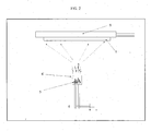
- the system for the detection of the texts is schematically shown in figure 4 .
- the item or the mark support (7) with the irradiated LiF film (9) is illuminated by a source (10) that emits in the region of blue-ultraviolet (wavelength ⁇ 460 nm); the irradiated portion of film will emit light in the red region of the spectrum (600-700 nm) detected with an instrument (11), for instance a fluorescence microscope, for identification marks which are not visible to the naked eye.
- the orange filter (12) is optional and is useful in the case the mark is observed with the naked eye to mask the diffused light from the illuminating source (10) which otherwise covers the light emitted by the same.
- the use of a blue-UV source is related to the fact that the absorbance spectrum typical for the F 2 and F 3 + colour centres created in the LiF is centred at about 450-460 nm.
- Every CC system is characterised by its own absorbance spectrum and emission spectrum.
- a further method to verify the originality of the mark is to measure either the absorbance spectrum (only possible if the film is deposited on transparent substrates) or the emission spectrum (possible with all systems) which is distinctive of that system.
- the absorbance spectrum only possible if the film is deposited on transparent substrates
- the emission spectrum possibly with all systems
- a reading system for the text is based on the use of an optical microscope where the conventional light source is replaced by a mercury vapour lamp which is characterised by an emission spectrum which extends to the ultraviolet region.
- This kind of microscope is usually provided with filters which allow to select a specific light band.
- the focussed objective lens of the microscope which generally both conveys excitation light on the sample and detects emitted light therefrom, avoids having an extremely diffused background light and thus the need for an orange filter.
- the detection means may be an extremely cost-effective system based on a solid state led capable of providing a maximum power of 1 W with an emission centred at 460 nm (real blue) supplied by two 1.5V AA batteries capable of providing a power supply of 3.0 V which is sufficient to supply power to the led; the device may also be equipped of a small lens for the focussing of the light.
- a transparent orange plastic sheet may be used (Kapton material).
- a use thereof on a large scale or on everyday use goods may for instance include the protection of films in order to avoid contact with the LiF film and/or the accidental removal.
- Such a protection may be obtained by means of the adhesion of a second transparent substrate (glass or plastic) by means of a common acrylic glue or transparent silicon resins.
- Such a further treatment does not imply any alteration of the LiF film and of the identification mark.
- the validation experimental activity for the inscriptions carried out on lithium fluoride (LiF) film has provided for the setting up of an experimental apparatus for vacuum regimens and low vacuum required for the evaporation of the LiF films and for the production of texts by means of an electronic cannon.
- the experimental apparatus used for the evaporation of LiF at atmospheric pressures consists of a vacuum chamber equipped with a small turbomolecular pump which allows it to achieve a base pressure of about 10 -7 mPa (mbars), and with a valve allowing to section the pumps and leave the apparatus in static vacuum (i.e. not pumped).
- An apparatus of this kind at the state of the art allows to maintain, if the pumping is interrupted, a HV environment even for days in the same regimen of pressure.
- the chamber is further provided with a valve connected each time to a gas cylinder of the preselected gas to control the introduction of the same in the chamber. By acting on this valve it is therefore possible to "fill" the static vacuum apparatus with the preselected gas at the atmospheric pressure and to maintain the system in these conditions.
- a sensor of the Pirani kind which is capable of measuring atmospheric pressures has been used as a pressure meter.
- a sample manipulator for items displaying sizes up to about 20 x 20 mm 2 and thicknesses up to 10 mm
- the LiF evaporator consists in a Ta sheet having a thickness of 0.1 mm folded on itself, the central part being flared and the end being joined so as to obtain a small "basket” (crucible).
- the ends have been connected to the poles of a current generator; this sliding through the walls of the crucible heats it in a resistive manner by means of a tungsten resistor.
- the power required to take the crucible filled with LiF to a temperature of at least 850°C at an ambient pressure corresponds to about 220 W.
- the power employed has to be increased because a greater number of molecules in the atmosphere around the crucible aids the-cooling thereof.
- a power of 140W is-required to heat the same crucible to the same temperature but in a HV environment.
- the power required has virtually been the same for all four gases.
- thermocouple of the K type has been filled with LiF having maximum dimensions of 1 mm; such an amount was sufficient to evaporate about 1 ⁇ m of LiF.
- the amount of LiF which may be evaporated on the sample decreases as well in the case in which the evaporation atmosphere is more "dense", this owing to the fact that the LiF molecules encounter more obstacles on their path to the sample and therefore may use up all of their kinetic energy before reaching the target. For this reason it has been necessary to draw the sample closer to about 8 cm from the evaporator and increase the evaporation time with respect to the conditions under HV. At this distance the deposition rate is virtually the same existing in the HV system at a distance between the sample and the evaporator of 19 cm equal to about 0.1 nm/s (1 A/s).
- the thickness of the LiF films obtained ranges from about 20 nm to 200 nm; below 20 nm the texts are no longer visible, whereas thicknesses greater than 70 nm do not improve the quality of texts.
- the thicknesses have been measured by means of AFM microscopy. Through the use of a piezoelectric scale, after the initial calibration, it has been possible to reproduce the thicknesses in the various operations in an accurate manner.
- the temperature on the samples because of the closeness of the LiF evaporator during the evaporation step can raise up to 80°C.
- the LiF films deposited by evaporation have been irradiated with an electronic cannon placed at a focal distance of 32 mm from the surface of the sample and mounted at a 90° angle with respect to the evaporator.
- the irradiation has been performed when LiF film was cooling down, the temperature was then comprised between 80 °C and room temperature. With a simple rotation of the manipulator it is therefore possible to pass from the evaporation step to the writing step.
- the cannon used is produced by SPECS GmbH (EQ 22 model).
- the size of the electronic beam produced by this cannon with the parameters used is of about 80 ⁇ m; this obviously determines the width of the texts which may be obtained with this instrument.
- the control of the texts has been carried out with a reduced size optical fluorescence microscope capable of a spatial resolution greater than that used for the texts.
- the large texts are formed by 5 numbers each of which having a size of 1 x 0.5 mm 2 and illuminated by a blue-UV lamp, they are easily readable with the naked eye: the small texts, instead, are formed by the same 5 numbers, each of which having a size of 0.6 x 0.3 mm 2 , these numbers are more easily readable with a fluorescence microscope.
- Some marks have been carried out using the synchrotron radiation with which very small texts may be obtained. Specifically, an alphanumeric code has been impressed on some nylon threads having a diameter of 0.1 mm covered by LiF; the texts have a size equal or smaller than 8 x 32 ⁇ m 2 .
- the fluorescent text carried out on a thread is shown in figure 5 .
- the materials used as a support for the texts to be subsequently applied to the tested objects during the course of this validation have been substantially glass and plastics as they are materials suitable for use in cultural objects.
- Commercial glass slides having a small thickness (0.1 mm) and different kinds of plastics (PET, PC, polypropylene, with thicknesses from 1 mm to 0.012 mm) have been used for the tests. All of these materials have been used in their original conformation, i.e. post-production conformation; no particular cleaning or surface alteration procedure (typically surface smoothing) has been applied. These surfaces were in any case characterised by a low surface roughness: a few dozen nanometres for plastics and a few hundred nanometres for glass.
- the simplest method is to protect a mark with an equivalent piece of substrate; for instance, a glass slide on which a text has been carried out with another glass slide glued with a transparent glue; or a plastic substrate with another plastic substrate if flexibility is to be maintained. All of these solutions have the property to totally protect the texts and increase the life-time as well as to avoid an accidental contact with the LiF.
- Some organic resins have been tested which are validated for human contact and are used in the electronic industry deposited by spin-coating on the texts; after the hardening of the resins, the texts were already visible.
Landscapes
- Chemical & Material Sciences (AREA)
- Crystallography & Structural Chemistry (AREA)
- Physics & Mathematics (AREA)
- Optics & Photonics (AREA)
- Analytical Chemistry (AREA)
- Physical Vapour Deposition (AREA)
- Dot-Matrix Printers And Others (AREA)
- Road Signs Or Road Markings (AREA)
- Laser Beam Processing (AREA)
Description
- The present invention relates to a method for marking an item consisting of the application to items or supports to be applied to items, the authenticity of which is to be guaranteed, or which are to be classified, of an identification mark obtained by the formation of colour centres with ionising radiations on a lithium fluoride (LiF) film, which are deposited at an ambient pressure.
- A Colour Centre (or CC) is a defect in a crystal solid including the vacancy of a negative ion at a site of the solid and the presence of an electron at the same site. Such defects are capable of absorbing light and lead crystals, which are normally transparent, to be coloured. Such defects may be obtained by irradiating the sample with an electromagnetic radiation or a ionising beam having the appropriate features.
- Many are the materials on which a CC may be created, but the most studied in the scientific field is without any doubt LiF. Indeed, the formation of CCs in LiF amorphous crystals and films has been studied with various types of irradiation: photons, electrons, neutrons and different kinds of ions. The reason why LiF results being the most studied material resides in that the main types of CCs which may be created (technically referred to as F2 and F3 +) may be produced in a fairly simple manner, in a high number and absorb and emit radiations in particularly favourable visible bands. Not least, LiF is a transparent material having determined optical properties and, in theory, it could have different applications even if, in practice, some of its features (as, for instance, high hygroscopicity) lead it to be poorly desirable for "actual" applications, as they make it difficult to manipulate.
- The current state of research on CCs focuses, as may be deduced from the most recent publications on scientific journals, on the study of the features of CCs created with the different ionising sources available; indeed, the different parameters characterising the formation thereof (e.g. density, details of the absorption and emission spectra) vary depending on the features of the source used for the formation of CCs (M. Kumar, F. Singh, S. A. Khan, A. Tripathi, D. K. Avasthi and A. C. Pandey, "Studies of swift heavy ion induced colour centres in LiF thin films deposited in silica substrates", J. Phys. D: Appl. Phys. 39 (2006) 2935-2940). There are also studies aimed at possible applications of CCs as, for instance, the possibility to generate waveguides thus forming "tracks" of CCs (R. M. Montereali and M. Piccinini, "Optical gain of F2 colour centres in LiF confining structures realised by electron-beam lithography", Optics Communications 209 (2002) 201-208; M. Cremona, J. A. M. Pereira, S. Pelli and-G. C. Righini, "Optical waveguides produced in LiF by MeV ion beam bombardment", Appl. Phys. Lett. 81 (2002) 4103-4105).
- However, in these fields, research is carried out with often very expensive instruments and in the attempt to isolate the measurement as much as possible from possible interferences due to the external environment. For instance, in many cases, LiF crystals are used instead of amorphous films, because crystals represent ordered sets of atoms with very little impurities possessing well-defined inherent properties which in many cases may be predicted in theory, whereas in amorphous films these may depend on the degree of "disorder" of the atoms forming them. Furthermore, the evaporations are carried out in vacuum chambers (very often in an ultra-high-vacuum environment (UHV)), because this guarantees that possible gaseous elements in the atmosphere are not deposited on the surface or even penetrate in the crystals thus altering measurements, whereas the irradiation of the samples occurs in the substantially optimal conditions of pressure, temperature and distance. All of these conditions make the application of this technology very difficult on a large scale because they imply very high costs for the required technical equipment, as well as a suitable preparation and operative manual ability of the technicians in charge.
- Another possible limitation for the use on a large scale derives from the fact that LiF is known to be dangerous if swallowed in great amounts or if it remains in contact for a long period with delicate parts of the body, as, for instance, the eyes. A use thereof on a large scale or on everyday use goods must therefore be provided with the possibility of operating in a protected manner in order to avoid environmental contaminations and with the final protection of the films to avoid con,tact with the film and/or its alteration and/or removal due to accidental contacts.
- The problem of guaranteeing the authenticity of high value items is deeply felt and many anti-counterfeiting systems have been suggested, mostly on laser marking technologies.
- This problem is particularly felt in the field of the preservation of cultural objects, where the need to be provided with identification systems for works of art represents a requirement both for anti-counterfeit purposes and classification purposes.
- Indeed, without considering the special care required when handling these artefacts, it is very difficult to apply anti-counterfeit or classification systems on items which must be displayed in front of a public and the view of which may not be "disturbed" by foreign elements. Clearly, this problem is worse in the case of small size items as, for instance, coins, archaeological finds, etc.
- The application of the CC technology for the implementation of marking methods for anti-counterfeit or classification purposes may be suitable to satisfy the need in this important field. Indeed, LiF is a transparent material which, if deposited in the form of a very thin film, does not alter the visible features of the item on which it is deposited. A text or a picture serving as an identification mark (hereinafter also referred to as mark) may be produced on this film by means of a ionising radiation used as a writing or drawing system, i.e. CCs may be created only on determined areas, which, if properly illuminated, emit light highlighting the luminous text or picture.
- Montereali R.M. et al. (Physica Status Solidii C, 2005, 2, 298-301) and Larciprete R: et al. (Applied Physics Letters, 2002, 80, 3862-3864) disclose the production of LiF films of different thickness, grown by thermal evaporation on several substrates, like glass and silicon, heated at a fixed temperature of 250° or 300°C. The process of deposition is carried out at the ESCA Microscopy beamline at the ELETTRA synchrotron radiation facility, a system operating in vacuum conditions as common practice for the LiF deposition. The use of vacuum conditions for LiF deposition is, in fact, motivated by the fact that in the field of surface science, to which the research on LiF colour centres pertains, the vacuum is considered a necessary condition in order to keep clean the surface and to allow an efficient ordered deposition with formation of CCs and electrons to reach the detection instruments.
-
US 6,211,526 discloses a marking method based on the formation of luminescent centres into an optically stimulable glass visible upon UV stimulation, being this glass matrix doped with several metals and activators suitable to induce defects onto the same matrix, such as for example an alkaline earth sulphide, activator Sm ions, and an additional coactivator dopant selected from Eu and Ce ions. No mention is given to label consisting of CC on LiF films. - It is therefore an object of the present invention to provide a marking method based on the exploitation of the formation of CCs on a LiF film by means of the use of ionising radiations, in which the application of LiF films and the following arrangement of the identification mark are carried out in mild conditions and by an easy application.
- It is another object of the present invention to provide the use of an easily available instrument also having reasonably restricted management costs.
- The method implemented by the inventors fulfils the above mentioned purposes, as it comprises the overcoming of some limitations deriving from the use of CCs in the conditions in which it is used in research laboratories where the aims are mainly scientific.
- In a first aspect, the present invention therefore provides a marking method of an item comprising at least the steps of:
- depositing by evaporation on the item or on a mark support to be applied to the item to be marked a lithium fluoride film having a thickness of at least 20 nm obtained by evaporating the same at an atmospheric pressure in an atmosphere consisting of air or nitrogen;
- irradiating the lithium fluoride film previously obtained by means of a ionising radiation beam having an energy of at least 0.4 keV controlled with computerised means to produce the desired identification mark.
- Optionally, the method object of the present invention comprises the further step of:
- detecting the presence of the previously obtained identification mark by illuminating the same by means of a light source emitting a blue-ultraviolet light and optional an orange filter.
- The advantages achievable with the present invention will become more apparent for the technician of the field from the following detailed description of particular embodiments given by way of example and not limitation, with reference to the following figures.
-
-
Figure 1 : the figure shows, by way of example, a diagrammatic view of a single chamber (1) connected with relative means (2) suitable to obtain the pressure and atmosphere conditions desired, in which the following are placed for performing the marking: a device for the evaporation of LiF formed by a crucible (6) for LiF (5) connected to a heating means (4); an item to be marked (7) placed on a movable item-holder (8) with appropriate means suitable for its rotation on a longitudinal or transverse axis; a means for the irradiation of the LiF film obtained by evaporation (3). The amplitude of the rotation on the longitudinal or transverse axis of the movable item-holder (8) substantially depends on the position of the evaporation and irradiation devices and is achievable with a manipulator (not shown in the figure) which allows the optimal orientation thereof towards the two above mentioned devices depending on their position. -
Figure 2 : the figure shows, by way of example, a diagrammatic view of the portion of apparatus in which the evaporation process is carried out, i.e. of the evaporator in which (5) is LiF placed in a crucible (6) which is heated by means of heating means (4) up to 850 °C, (7) is the item to be marked, with the deposition of a vaporised LiF film, placed on an appropriate movable item-holder (8). -
Figure 3 : the figure shows, by way of example, a diagrammatic view of the portion of apparatus with which the irradiation process of the LiF film is carried out and the figure specifically shows an instrument capable of emitting an electronic beam of the appropriate energy and i.e. an electronic cannon (3) placed in a chamber (1) connected to means suitable to obtain the desired vacuum (2) placed at an appropriate distance from the object to be marked (7) placed in turn on the movable item-holder (8). -
Figure 4 : the figure shows, by way of example, a diagrammatic view of the apparatus for the detection of the identification mark in which (10) is a source of exciting light which emits a radiation in the blue-UV region which is incident on the irradiated LiF film (9) deposited on the item (7) and (11) is a detection system for the fluorescent radiation emitted by the identification mark and (12) a filter suitable to select the light deriving from the identification mark. -
Figure 5 : the figure shows, by way of example, a text obtained on a thread made of nylon having a diameter of 0.1 mm; the name "ELETTRA" has been impressed. - The largest text that may be read has a size of 8 x 36 µm, whereas the smallest that may not be read at this magnification has a size of 2 x 10 µm.
-
Figure 6 : the figure shows, by way of example: a) a photograph of the back of a Roman period coin on which the LiF coating has been carried out and the text has been carried out, illuminated by natural light; b) the same coin illuminated by blue-UV light, the photograph has been obtained through an orange filter. - The marking method which is the object of the present invention is focused on the production of CCs on an amorphous lithium fluoride (LiF) film that is evaporated so as to avoid the use of crystals and avoid the use of vacuum systems for the step of depositing LiF. Atmospheric pressure evaporations have surprisingly produced positive results, in particular in the case in which the evaporation atmosphere consists of air or nitrogen. In this manner, the production costs for the film are considerably cut down. On the other side, the preferential use of an electronic cannon controlled by a computer for the production of identification marks, which requires a vacuum environment for its operation in its most cost-effective and thus more suitable for large scale use - forms, is justified in that any kind of identification mark may be carried out, both in written form and in the form of a logo, as it behaves as a writing or drawing means, for example, as an "electronic paintbrush".
- The possible use of this marking technology on especially high value items has been handled in the following manner. As it is known that LiF is a material which is particularly inert towards other materials, but the certainty concerning this matter in the case of a specific material must be tested, two possible variants of the method have been developed: a) the deposition of LiF and its "writing" directly on the item (in case the safety conditions and the stability have been checked) and b) the production of identification marks on different substrates to be applied later to the item involved.
- That is because in the field of cultural objects (as in all fields of high value items) each section is provided with a series of materials which are "certified" and may be safely used. For instance, the insertion of a piece of glass by means of a special acrylic glue on the canvas of a painting is a process which is authorised by the authorities in charge, thus in this case the marking may be carried out on a mark support to be applied later to the item to be marked. Therefore, in this case, it is no longer important to investigate the effect of LiF on the material of the item on the long period. Similar considerations apply in the case of the safety of the ionizing radiation beam used to carry out the identification mark and preferred for the object method of the present invention; it also being totally "harmless" in the conditions defined with the present method, even if in some cases its indirect use on the item could be preferable.
- The marking method object of the present invention comprising the steps of:
- depositing by evaporation on the item or on a mark support to be applied to the item to be marked a lithium fluoride film having a thickness of at least 20 nm obtained by evaporating the LiF molecules at an atmospheric pressure in an atmosphere consisting of air or nitrogen;
- irradiating the film obtained by means of a ionising radiation beam having an energy of at least 0.4 keV controlled by computerised means to carry out the desired identification mark;
- detecting the presence of the identification mark previously obtained by illuminating the same by means of a source of blue-ultraviolet light and possibly filtering the emitted light by means of an orange filter
- in some of its forms is carried out in the conditions which have been described in detail hereafter with reference to the figures.
- In order to obtain a mark of good quality in the condition of atmospheric pressure and in an atmosphere consisting of air or nitrogen the critical step of the method according the invention is the evaporation of LiF; the relevant parameters for the formation of CC are essentially the evaporation rate of LiF and the temperature of the item or the mark support to be applied thereto. As it will be readily apparent from the following detailed description of the invention these are respectively comprised in the range from 0.02 nm/s (0.2 A/s) to 0.3 nm/s (3 A/s) and from 15°C to 90°C. The same range of temperature is applied during the irradiation of the item or the mark support.
-
Figure 1 shows a possible configuration of an apparatus required to carry out the anti-counterfeit method, which is the object of the invention. In this embodiment thereof, such an apparatus is comprised of a movable item-holder on which the item to be marked may be placed, a device for the evaporation of LiF and an instrument suitable for the emission of a ionising radiation beam having an appropriate energy. Such devices are placed in a single chamber (1) serving to protect the operator and in which the appropriate pressure and atmosphere conditions may be obtained when the marking is carried out. For this purpose, the chamber (1) is therefore connected with relative means suitable to obtain the pressure and atmosphere conditions desired (2) during the two steps of evaporating and irradiating. In particular: - the device for the evaporation of LiF is formed by a crucible (6) for LiF (5) connected to a heating means (4);
- the means (3) to irradiate the LiF film, obtained by evaporation, is an instrument emitting an electronic beam such as an electronic cannon or an instrument emitting a photon beam generated, for instance, from a synchrotron;
- the item to be marked (7) is placed on an item-holder (8) which is movable by appropriate means suitable for its rotation on a longitudinal or transverse axis, such a rotation on the longitudinal or transverse axis of the item-holder (8) substantially depending on the position of the evaporation and irradiation devices and such a rotation being obtainable by means of a manipulator (not shown in the figure) that allows the optimal orientation towards the two mentioned devices of the item-holder (8).
- Typically, the means (2) (not shown in the figures) are, as known to a technician of the field, vacuum pumps and gas cylinders provided with appropriate closing and opening valves.
- Such an instrument for the irradiation of the LiF film is controlled by computerised means (not shown in the figures) in order to obtain the desired identification mark. Hereinafter there are described a marking method which is the object of the invention in its general and specific aspects and the results obtained with reference respectively to
figures 2-4 and5-6 . - With reference to
figure 2 , the item (7) on which the identification mark is to be produced is mounted on an object-holder (8). At a distance in the range from 5 to 30 cm and preferably 8 cm there is placed an evaporator for LiF, which in a possible embodiment thereof is formed by a sheet of any metal alloy which is resistant to oxidation at high temperatures such as, for instance, some common kinds of steel such as AISI 310 type stainless steel or others, or a metal which does not oxidise easily at high temperatures chosen among tantalum and molybdenum having a thickness in the range from 0.05 mm to 0.3 mm, preferably 0.1 mm, folded on itself with the central flared part and the ends sealed so as to obtain a small "basket" or crucible (6). The crucible (6), which in a possible form thereof may have a volumetric size in the range from 0.2 to 1 cm3, preferably about 0.5 cm3, is filled with LiF crystals having a size in the range from 0.01 to 5 mm, preferably 0.5-2 mm to ease evaporation. Amorphous LiF powders having comparable size do not substantially affect the evaporation process of the same in the intended conditions with the anti-counterfeit method which is the object of the invention. Preferably the ends of the crucible (6) are connected to the poles of a current generator (4); by flowing through the walls of the crucible the current resistively heats it. The power required to take the crucible (6) having the above mentioned size and filled with LiF to a temperature of at least 850 °C (measured by means of a thermocouple of the K type) at an ambient pressure corresponds to at least 220W. - Larger crucible (6) sizes and thicknesses for the walls thereof are possible; in this case, in order to obtain the desired evaporation of LiF, it will be required, as known by a technician in the field, to apply a higher energy, for instance, thermal energy. The measurement of the evaporation temperature may be carried out in different known ways, whereas the measurement of the flow is controlled as usual by means of a piezoelectric scale. With these parameters the evaporation flow measured by a piezoelectric scale at the above mentioned distance results being in the range from 0.02 to 0.3 nm/s (0.2 to 3 A/s) and at this distance the area covered by LiF results being equal to about 50 cm2.
- The thinnest films on which it has been possible to carry out a visible text have a thickness of at least 20 nm; the intensity of the text increases as the thickness of the film increases until it reaches a maximum at about 70 nm; greater thicknesses (even up to 200 nm) do not significantly improve the properties of the identification mark, but they may be required proportionally to the roughness of the item or of the support on which the identification mark is placed.
- The evaporation may be carried out in an atmosphere consisting either of air or of an inert gas such as nitrogen.
- In the case of evaporation at an atmospheric pressure in air the crucible (6) may be formed by any metal alloy or metal which does not easily oxidise (and therefore break) at high temperatures, whereas in the case the atmosphere is formed by an inert gas (nitrogen) the possibility of oxidation is reduced and therefore the choice among metals and/or metal alloys broadens. Tantalum is in any case the preferred material among the previously mentioned metals.
- In order to obtain films having a thickness in the range from 20 to 200 nm, the evaporation rate is in the range from 0.02 nm/s (0.2 A/s) to 0.3 nm/s (3 A/s) and the evaporation is carried out for a period of time in the range from 60 seconds to 170 minutes. The preferred evaporation rate is 0.1 nm/s (1 A/s) for a distance of the item or mark support to be applied thereon of 8 cm.
- In general, films having this thickness naturally adhere to items through the formation of chemical or physical bonds between LiF and the materials; the tests performed on many materials and artefacts (glass, plastics, metals, paper, coins, various items) have demonstrated that thin LiF films may be deposited (and later the identification mark may be carried out) on most materials.
- In relation to the thickness of the films, the surface roughness of the items could have a great importance for an effective carrying out of the identification mark following the irradiation and thus for the success, for instance, of a text. The tests performed on some archaeological finds (coins and ancient buckles) have demonstrated in any case that also on items characterised by a very marked surface roughness, films having a thickness of 100-200 nm are required to produce a good quality identification mark.
- It is known that the temperature of substrate during the deposition of LiF and its irradiation can influence the nature of the CC that can be created, the attainment of CC of defined properties is still a matter of research and discussion in the scientific community". For the purposes of the present invention the Inventors have demonstrated that performing the deposition of the LiF and the irradiation at a substrate temperature in the range from 15°C to 90°C results in the creation of marks of good quality. The preferred temperature is 25 °C.
- With reference to
figure 3 , when the instrument emitting ionising radiations (3) is an electronic cannon, it is required to operate under vacuum conditions. In this case in the chamber (1) a vacuum condition in the range from 5 x 10⁻³ mPa (mbars) to 5 x 10⁻⁷ mPa (mbars) is obtained or the substrate on which the LiF film has been deposited is introduced in a vacuum chamber at least in the same vacuum regimen, preferably high-vacuum (HV) (pressure < 1 x 10⁻⁴ mPa (mbars)), where the electronic cannon (3) is present, the beam of which may be deviated horizontally and vertically in a controlled manner. The electron energy used to carry out the identification mark is comprised in the range from 1 to 5 keV, preferably 3 keV, and the emission current of the cannon is in the range from 0.01 µA to 0.1 µA, preferably equal to about 0.05 µA. The distance between the cannon and the sample depends on the kind of electronic cannon employed, usually being that recommended by the manufacturer of the cannon; in the specific case it corresponds to a focal distance of 32 mm. - The irradiation time is closely related to the quality and size of the texts which may be obtained. Overexposures in the irradiation thus widen the line of the text and modify the structure thereof (no longer a full line, but two parallel lines instead). The result is a blurred illegible text. Instead, underexposures do not create a number of CCs sufficient to allow to easily read the text. The irradiation time is related both to the energy of the electronic beam and to the emission current of the cannon used. For the purposes of the present invention the irradiation time for every dot of the text is in the range from 1 to 30 seconds and is preferably equal to 10 seconds.
- Another aspect which is especially important for the quality of the mark is the size of the spot of the ionising radiation beam which must be in the range from 200 nm to 2 mm and is preferably 80 µm.
- Still with reference to
figure 2 , when the instrument emitting ionising radiations (3) is the Synchrotron radiation (and therefore the ionising beam is formed by photons), it is required to operate under high vacuum conditions. In this case, the substrate on which the LiF film has been deposited is introduced in a vacuum chamber (1) in a regimen in the range from 1 x 10-11 mPa (mbars) to 5 x 10⁻⁶ mPa (mbars) and preferably ultra-high vacuum (UHV) (pressure < 10-9 mPA (mbars)) where there is a synchrotron radiation beam which may be deviated horizontally and vertically in a controlled manner. The energy of the photons used for the carrying out of the identification mark is in the range from 0.4 to 1.2 keV and is preferably 0.65 keV and the density of photons on the sample is in the range between 1017 and 1020 photons/seconds/cm2 and is preferably equal to about 1019 photons/seconds/cm2. The system employed includes the focussing of the photon beam by means of Fresnel lenses (Zone Plates), therefore the texts must be carried out at a focal distance which in this specific case is equal to 10 mm. For the purposes of the present invention the irradiation time for every dot of the text is in the range from 10 to 100 mseconds and is preferably equal to 10 mseconds. The size of the photon spot, which determines the size of the identification mark, may be varied by changing the kind of focussing lens and typically has values in the range between 200 nm and 5 µm. - By way of example, it may be mentioned that by the method which is the object of the invention the smallest area with CCs ever achieved may be obtained, it having a size corresponding to about 300-400 nm, this result has been obtained with a ionising source which had a definitely smaller size (some tens of nm). The reason for this is that the physical process for the creation of the CCs automatically broadens the spatial size. If a range is to be indicated for the size of the ionising radiation spot to be used for the marking method of the invention, 200 nm may be indicated (in the case of the Synchrotron radiation) as a lower limit and 2 mm as the maximum width obtained by the electronic cannon (corresponding to a range of widths of the areas with the CCs between 500 nm and 2 mm). For all practical purposes, in any case, the size of the beam (except for the case of the lower limit of 200 nm) is chosen on the basis of the size of the identification mark to be obtained .
- The instrument emitting the ionising radiation beam (3) is controlled by a computer (not shown in the figures) which, by using it as writing means or paintbrush, allows to produce identification marks in the form of characters and logos.
- The areas of the LiF film irradiated by the ionising radiation beam result being indistinguishable from the rest of the film under natural light.
- The system for the detection of the texts is schematically shown in
figure 4 . The item or the mark support (7) with the irradiated LiF film (9) is illuminated by a source (10) that emits in the region of blue-ultraviolet (wavelength < 460 nm); the irradiated portion of film will emit light in the red region of the spectrum (600-700 nm) detected with an instrument (11), for instance a fluorescence microscope, for identification marks which are not visible to the naked eye. The orange filter (12) is optional and is useful in the case the mark is observed with the naked eye to mask the diffused light from the illuminating source (10) which otherwise covers the light emitted by the same. The use of a blue-UV source is related to the fact that the absorbance spectrum typical for the F2 and F3 + colour centres created in the LiF is centred at about 450-460 nm. - Every CC system is characterised by its own absorbance spectrum and emission spectrum. A further method to verify the originality of the mark is to measure either the absorbance spectrum (only possible if the film is deposited on transparent substrates) or the emission spectrum (possible with all systems) which is distinctive of that system. There are systems available commercially which measure these spectra.
- A reading system for the text is based on the use of an optical microscope where the conventional light source is replaced by a mercury vapour lamp which is characterised by an emission spectrum which extends to the ultraviolet region. This kind of microscope is usually provided with filters which allow to select a specific light band. The focussed objective lens of the microscope, which generally both conveys excitation light on the sample and detects emitted light therefrom, avoids having an extremely diffused background light and thus the need for an orange filter.
- For larger marks which are readable with the naked eye, the detection means may be an extremely cost-effective system based on a solid state led capable of providing a maximum power of 1 W with an emission centred at 460 nm (real blue) supplied by two 1.5V AA batteries capable of providing a power supply of 3.0 V which is sufficient to supply power to the led; the device may also be equipped of a small lens for the focussing of the light. As a filter, a transparent orange plastic sheet may be used (Kapton material).
- A use thereof on a large scale or on everyday use goods may for instance include the protection of films in order to avoid contact with the LiF film and/or the accidental removal. Such a protection may be obtained by means of the adhesion of a second transparent substrate (glass or plastic) by means of a common acrylic glue or transparent silicon resins. Such a further treatment does not imply any alteration of the LiF film and of the identification mark.
- The validation experimental activity for the inscriptions carried out on lithium fluoride (LiF) film has provided for the setting up of an experimental apparatus for vacuum regimens and low vacuum required for the evaporation of the LiF films and for the production of texts by means of an electronic cannon. The experimental apparatus used for the evaporation of LiF at atmospheric pressures consists of a vacuum chamber equipped with a small turbomolecular pump which allows it to achieve a base pressure of about 10-7 mPa (mbars), and with a valve allowing to section the pumps and leave the apparatus in static vacuum (i.e. not pumped). An apparatus of this kind at the state of the art allows to maintain, if the pumping is interrupted, a HV environment even for days in the same regimen of pressure. The chamber is further provided with a valve connected each time to a gas cylinder of the preselected gas to control the introduction of the same in the chamber. By acting on this valve it is therefore possible to "fill" the static vacuum apparatus with the preselected gas at the atmospheric pressure and to maintain the system in these conditions. A sensor of the Pirani kind, which is capable of measuring atmospheric pressures has been used as a pressure meter.
- In such a chamber there is placed a sample manipulator for items displaying sizes up to about 20 x 20 mm2 and thicknesses up to 10 mm, whereas the LiF evaporator consists in a Ta sheet having a thickness of 0.1 mm folded on itself, the central part being flared and the end being joined so as to obtain a small "basket" (crucible). The ends have been connected to the poles of a current generator; this sliding through the walls of the crucible heats it in a resistive manner by means of a tungsten resistor.
- The power required to take the crucible filled with LiF to a temperature of at least 850°C at an ambient pressure corresponds to about 220 W. In the case of pressures higher than the HV regimen, the temperature being equal, the power employed has to be increased because a greater number of molecules in the atmosphere around the crucible aids the-cooling thereof. By way of example, a power of 140W is-required to heat the same crucible to the same temperature but in a HV environment. In the case of the 4 gases tested at an atmospheric pressure (air, nitrogen, helium, argon) the power required has virtually been the same for all four gases.
- Also in this case the temperatures have been monitored with a thermocouple of the K type. The crucible having volumetric dimensions of about 0.5 cm3 has been filled with LiF having maximum dimensions of 1 mm; such an amount was sufficient to evaporate about 1 µm of LiF.
- The evaporation conditions being the same, the amount of LiF which may be evaporated on the sample decreases as well in the case in which the evaporation atmosphere is more "dense", this owing to the fact that the LiF molecules encounter more obstacles on their path to the sample and therefore may use up all of their kinetic energy before reaching the target. For this reason it has been necessary to draw the sample closer to about 8 cm from the evaporator and increase the evaporation time with respect to the conditions under HV. At this distance the deposition rate is virtually the same existing in the HV system at a distance between the sample and the evaporator of 19 cm equal to about 0.1 nm/s (1 A/s).
- The thickness of the LiF films obtained ranges from about 20 nm to 200 nm; below 20 nm the texts are no longer visible, whereas thicknesses greater than 70 nm do not improve the quality of texts. The thicknesses have been measured by means of AFM microscopy. Through the use of a piezoelectric scale, after the initial calibration, it has been possible to reproduce the thicknesses in the various operations in an accurate manner. The temperature on the samples because of the closeness of the LiF evaporator during the evaporation step can raise up to 80°C. Subsequently, the LiF films deposited by evaporation have been irradiated with an electronic cannon placed at a focal distance of 32 mm from the surface of the sample and mounted at a 90° angle with respect to the evaporator. The irradiation has been performed when LiF film was cooling down, the temperature was then comprised between 80 °C and room temperature. With a simple rotation of the manipulator it is therefore possible to pass from the evaporation step to the writing step. The cannon used is produced by SPECS GmbH (EQ 22 model). The size of the electronic beam produced by this cannon with the parameters used is of about 80 µm; this obviously determines the width of the texts which may be obtained with this instrument.
- During the initial tests the parameters of the electronic cannon and the exposure time have been adjusted. These parameters have resulted substantially independent from the thickness of the LiF film to irradiate.
- To validate the object method of the invention different experimental tests have been carried out according to 2 distinct modes depending on the type of items to be marked and on the technical difficulties encountered:
- a) directly on the object
- b) on an external mark support to be subsequently applied to the object.
- Different kinds of samples (Si, metal plates, plastics) with LiF evaporations obtained at atmospheric pressures of air, nitrogen, helium and argon have been produced. For the direct comparison monocrystal samples of Si have been used so as to have the same support for every evaporation. The texts on these samples have then been carried out in a HV environment.
- The control of the texts has been carried out with a reduced size optical fluorescence microscope capable of a spatial resolution greater than that used for the texts.
- The samples produced by evaporating LiF in air or nitrogen have confirmed the presence of the texts characterised by the same intensity of the equivalents produced under HV. Only a closer analysis carried out under an optical microscope has detected a more uniform and less dotted structure of the line shape.
- The samples produced in helium and argon atmospheres (in spite of the longer evaporation times) have not displayed the presence of any text. In the following table a summary is shown of the results obtained in the different evaporation conditions indicated.
atmosphere pressure time results Air 5.4 x 10² mPa (mbars) 20 mins Visible texts different from those obtained under vacuum displaying a more even and less dotted structure N2 3.8 x 10² mPa (mbars) 20 mins Visible texts different from those obtained under vacuum displaying a more even and less dotted structure He2 5.4 x 10² mPa (mbars) 40 mins No visible text Ar 5.4 x 10² mPa (mbars) 45 mins No visible text - The first tests for the evaporation of the LiF films and the carrying out of the marks have demonstrated that the surfaces of different items may be subjected to various processes required to carry out, for instance, texts in a completely transparent manner.
- Considered the virtually total absence of protocols for the use of these marks on cultural objects, it has been decided to produce a certain number of marks having different size and support, to be directly tested on the artefacts during the everyday activities concerning restoration and preservation of the same. For this
reason 5 small size (10-30 mm2) thin (0.1 mm) glass marks protected by as many glass slides, 4 small size (10-20 mm2) thin (0.2 mm) plastic supports and some thin nylon threads (diameter 0.1 mm) with very small texts have been prepared. The texts have been carried out in two different formats: large texts and small texts. The large texts are formed by 5 numbers each of which having a size of 1 x 0.5 mm2 and illuminated by a blue-UV lamp, they are easily readable with the naked eye: the small texts, instead, are formed by the same 5 numbers, each of which having a size of 0.6 x 0.3 mm2, these numbers are more easily readable with a fluorescence microscope. Some marks have been carried out using the synchrotron radiation with which very small texts may be obtained. Specifically, an alphanumeric code has been impressed on some nylon threads having a diameter of 0.1 mm covered by LiF; the texts have a size equal or smaller than 8 x 32 µm2. The fluorescent text carried out on a thread is shown infigure 5 . - Furthermore, different tests have been carried out on different coins, both ancient and modern, which in virtually all cases have produced good quality texts. By way of example of the marks obtainable by the present method, in
figure 6 there are shown pictures of texts carried out on a Roman period coin as they appear under visible light and under blue-UV illumination. The series of 5 numbers is clearly visible. - The materials used as a support for the texts to be subsequently applied to the tested objects during the course of this validation have been substantially glass and plastics as they are materials suitable for use in cultural objects. Commercial glass slides having a small thickness (0.1 mm) and different kinds of plastics (PET, PC, polypropylene, with thicknesses from 1 mm to 0.012 mm) have been used for the tests. All of these materials have been used in their original conformation, i.e. post-production conformation; no particular cleaning or surface alteration procedure (typically surface smoothing) has been applied. These surfaces were in any case characterised by a low surface roughness: a few dozen nanometres for plastics and a few hundred nanometres for glass.
- The processes for the deposition of LiF and for the carrying out of texts on various materials (comprising ancient coins) have demonstrated the neutrality of these processes; the LiF films in the range of thicknesses used in the tests (from 20 to 200 nm) are virtually invisible and do not alter the surface chemistry of the samples, the texts carried out with electronic cannons and with synchrotron radiation do not even slightly modify the irradiated samples from a chemical and/or morphological point of view.
- After 10 months, after many writing tests and following operations of erasion, no variations were noticed on the surface of the coins. The removal of the LiF film takes place by the mechanical friction with paper or cotton. In the case of supported marks there are attaching materials (glues) the use of which is allowed for these high value goods Specifically, an acrylic glue has been tested which may be also applied on the exposed sides of the paintings and has proved perfectly compatible with the texts and LiF films. Furthermore, it has been possible to remove the glue with specific solvents (these are used by restorers as well) leaving the mark unaltered.
- The marks supported by plastic and glass films have been subjected to controlled temperature and humidity stability tests: a) 4h at T = 80 ± 2°C; b) 4h at T = 40 ± 2°C and relative humidity f = 90%; c) 16h at T = -20 ± 2°C. The intensity and the shape of the texts has been measured before and after performing the tests, without detecting any modification. Many other "empirical" tests have been performed to test the marks in "everyday" use, for instance, exposing them to environmental climate conditions, attaching and detaching them many times from the items, frequently manipulating them, etc.; these tests have given very positive results therefore confirming the resistance and stability of the marks.
- However, in order to avoid any risk potentially deriving from LiF, the simplest method is to protect a mark with an equivalent piece of substrate; for instance, a glass slide on which a text has been carried out with another glass slide glued with a transparent glue; or a plastic substrate with another plastic substrate if flexibility is to be maintained. All of these solutions have the property to totally protect the texts and increase the life-time as well as to avoid an accidental contact with the LiF. Some organic resins have been tested which are validated for human contact and are used in the electronic industry deposited by spin-coating on the texts; after the hardening of the resins, the texts were already visible.
Claims (22)
- A method for marking an item comprising at least the steps of:- depositing by evaporation a lithium fluoride film having a thickness of at least 20 nm obtained by evaporating the same on the item or on a mark support to be applied to the item to be marked;- irradiating the previously obtained lithium fluoride film by means of a ionising radiation beam having an energy of at least 0.4 keV controlled by computerised means to carry out the desired identification mark,
wherein the depositing step is performed at an atmospheric pressure and in an atmosphere consisting of air or nitrogen. - The method according to claim 1 comprising the further step of:- detecting the presence of the identification mark obtained by illuminating the same by means of a light source emitting a blue-ultraviolet light.
- The method according to claim 1 comprising the further steps of:- detecting the presence of the identification mark obtained by illuminating the same by means of a light source emitting a blue-ultraviolet light;- controlling the authenticity of the identification mark by means of the measurement of the absorbance or emission spectrum of the same.
- The method according to claim 1, wherein the temperature of the item or of a mark support to be applied to the item during the steps of evaporation and irradiation is in a range comprised from 15°C to 90°C.
- The method according to claim 4, wherein said temperature is 25°C.
- The method according to claim 1, wherein a lithium fluoride film having a thickness in the range from 20 to 200 nm is obtained by:- evaporating lithium fluoride at a flow rate in the range from 0.02 nm/s (0.2 Å/s) to 0.3 nm/s (3 Å/s) for a time in the range from 60 seconds to 170 minutes;- placing the item or the mark support at a distance in the range from 5 to 30 cm from the evaporator.
- The method according to claim 6, wherein the lithium fluoride film is obtained by:- evaporating lithium fluoride with a flow rate of 0.1 nm/s (1 Å/s);- placing the item or the mark support at a distance of 8 cm from the evaporator.
- The method according to claims 6 and 7, wherein lithium fluoride has a granulometry in the range from 0.01 to 5 mm.
- A method according to claim 8, wherein lithium fluoride has a granulometry of 0.5-2 mm.
- The method according to claim 1, wherein the irradiation is obtained under vacuum conditions in the range from 5 x 10⁻³ to 5 x 10⁻⁷ mPa (mbars) with a ionising radiation beam having an energy in the range from 1 to 5 keV emitted by an electronic cannon with an emission current in the range from 0.01 to 0.1 µA.
- The method according to claim 10, wherein the irradiation is obtained under vacuum conditions of < 1 x 10⁻⁴ mPa (mbars) with a ionising radiation beam having an energy of 3 keV emitted by an electronic cannon with an emission current of 0.05 µA.
- The method according to claims 10 and 11, wherein the irradiation is obtained for a time in the range from 1 to 30 seconds.
- The method according to claim 12, wherein the irradiation is obtained for a time of 10 seconds.
- The method according to claims 10 and 11, wherein the ionising radiation beam spot has a size in the range from 200 nm to 2 mm.
- The method according to claim 14, wherein the ionising radiation beam spot has a size of 80 µm.
- The method according to claim 1, wherein the irradiation is obtained under vacuum conditions in the range from 1 x 10-11 to 5 x 10⁻⁶ mPa (mbars) with a ionising radiation beam having an energy in the range from 0.4 to 1.2 keV with a density in the range from 1017 to 1020 photons/seconds/cm2 emitted by a synchrotron.
- The method according to claim 16, wherein the irradiation is obtained under vacuum conditions <10-9 mPa (mbars) with a ionising radiation beam having an energy of 0.65 keV with a density of 1019 photons/seconds/cm2 emitted by a synchrotron.
- The method according to claims 16 and 17, wherein the irradiation time for each dot of the identification mark is in the range from 10 to 100 mseconds.
- The method according to claim 18, wherein the irradiation time for each dot of the identification mark is 10 mseconds.
- The method according to claims 16 and 17, wherein the ionising radiation beam has a size of the photon spot is in the range from 200 nm to 5 µm.
- The method according to claims 2 and 3, wherein the identification mark is detected by means of a fluorescence microscope.
- The method according to claims 2 and 3, wherein the identification mark is detected by means of an instrument emitting a light in the blue-ultraviolet region which illuminates the identification mark and an orange filter.
Applications Claiming Priority (2)
| Application Number | Priority Date | Filing Date | Title |
|---|---|---|---|
| IT000036A ITPD20070036A1 (en) | 2007-02-05 | 2007-02-05 | METHOD OF MARKING OF AN OBJECT BASED ON COLOR CENTERS |
| PCT/EP2008/051320 WO2008095884A1 (en) | 2007-02-05 | 2008-02-04 | A method for marking an item based on colour centres |
Publications (2)
| Publication Number | Publication Date |
|---|---|
| EP2111342A1 EP2111342A1 (en) | 2009-10-28 |
| EP2111342B1 true EP2111342B1 (en) | 2014-07-30 |
Family
ID=38610859
Family Applications (1)
| Application Number | Title | Priority Date | Filing Date |
|---|---|---|---|
| EP08708624.5A Not-in-force EP2111342B1 (en) | 2007-02-05 | 2008-02-04 | A method for marking an item based on colour centres |
Country Status (4)
| Country | Link |
|---|---|
| US (1) | US8389069B2 (en) |
| EP (1) | EP2111342B1 (en) |
| IT (1) | ITPD20070036A1 (en) |
| WO (1) | WO2008095884A1 (en) |
Cited By (1)
| Publication number | Priority date | Publication date | Assignee | Title |
|---|---|---|---|---|
| TWI798700B (en) * | 2021-05-19 | 2023-04-11 | 陽程科技股份有限公司 | Laser transfer printing equipment and its transfer printing method to substrate |
Families Citing this family (6)
| Publication number | Priority date | Publication date | Assignee | Title |
|---|---|---|---|---|
| ITRM20080218A1 (en) | 2008-04-23 | 2009-10-24 | Enea Ente Per Le Nuove Tecnologie, L Energia E... | INVISIBLE WRITING METHOD BASED ON LITHOGRAPHY OF LUMINESCENT MATERIALS, ITS READING METHOD AND ANTI-COUNTERFEIT MARKING SYSTEM. |
| IT1397095B1 (en) | 2009-12-18 | 2012-12-28 | Inst Jozef Stefan | LITHIUM FLUORIDE POWDER MATERIAL CONTAINING COLOR CENTERS, METHOD OF PREPARING THE SAME AND ITS USE |
| WO2015084392A1 (en) | 2013-12-06 | 2015-06-11 | Hewlett-Packard Development Company, L.P. | Object-based user authentication |
| KR20190009844A (en) * | 2016-06-21 | 2019-01-29 | 어플라이드 머티어리얼스, 인코포레이티드 | Interphase layer for improved lithium metal cycling |
| CN115570891A (en) * | 2021-06-21 | 2023-01-06 | 阳程科技股份有限公司 | Laser transfer printing equipment and method for laser transfer printing to substrate |
| GB2629465B (en) * | 2023-10-17 | 2025-05-07 | Quantum Base Ltd | Optically readable physical unclonable functions on inorganic materials |
Family Cites Families (5)
| Publication number | Priority date | Publication date | Assignee | Title |
|---|---|---|---|---|
| GB1587232A (en) | 1977-08-25 | 1981-04-01 | Issec Sa | Flat screen solid state display and memory device utilising colour centres |
| US6013601A (en) | 1997-09-12 | 2000-01-11 | Nocopi Technologies, Inc. | Laser printing method and substrate |
| US6211526B1 (en) | 1998-09-30 | 2001-04-03 | The United States Of America As Represented By The Secretary Of The Navy | Marking of materials using luminescent and optically stimulable glasses |
| ITTO20020575A1 (en) | 2002-07-02 | 2004-01-02 | Enea Ente Nuove Tec | METHOD OF DETECTION OF MICROMETRIC AND SUB-MICROMETRIC IMAGES BY IRRADIATION OF A MASK OR BIOLOGICAL SAMPLE WITH RA |
| US20050281948A1 (en) * | 2004-06-17 | 2005-12-22 | Eastman Kodak Company | Vaporizing temperature sensitive materials |
-
2007
- 2007-02-05 IT IT000036A patent/ITPD20070036A1/en unknown
-
2008
- 2008-02-04 WO PCT/EP2008/051320 patent/WO2008095884A1/en not_active Ceased
- 2008-02-04 EP EP08708624.5A patent/EP2111342B1/en not_active Not-in-force
- 2008-02-04 US US12/449,270 patent/US8389069B2/en not_active Expired - Fee Related
Cited By (1)
| Publication number | Priority date | Publication date | Assignee | Title |
|---|---|---|---|---|
| TWI798700B (en) * | 2021-05-19 | 2023-04-11 | 陽程科技股份有限公司 | Laser transfer printing equipment and its transfer printing method to substrate |
Also Published As
| Publication number | Publication date |
|---|---|
| US20100068374A1 (en) | 2010-03-18 |
| US8389069B2 (en) | 2013-03-05 |
| WO2008095884A1 (en) | 2008-08-14 |
| ITPD20070036A1 (en) | 2008-08-06 |
| EP2111342A1 (en) | 2009-10-28 |
Similar Documents
| Publication | Publication Date | Title |
|---|---|---|
| US8389069B2 (en) | Method for marking an item based on colour centres | |
| AU746557B2 (en) | Diamond or gemstone marking by plurality of grooves | |
| JPH04231398A (en) | Method for adhering seal for diamond | |
| Guo et al. | Large‐scale horizontally aligned ZnO microrod arrays with controlled orientation, periodic distribution as building blocks for chip‐in piezo‐phototronic LEDs | |
| Diop et al. | Magnetron sputtering deposition of Ag/TiO2 nanocomposite thin films for repeatable and multicolor photochromic applications on flexible substrates | |
| Baril et al. | Optical excitation spectra of trapped electrons in irradiated feldspars | |
| WO2023055729A1 (en) | Zirconium-coated ultra-thin, ultra-low density films for euv lithography | |
| Lagomarsino et al. | The center for production of single-photon emitters at the electrostatic-deflector line of the Tandem accelerator of LABEC (Florence) | |
| Demos et al. | Surface defect generation in optical materials under high fluence laser irradiation in vacuum | |
| Mochizuki et al. | Reversible photoinduced spectral change in Eu 2 O 3 at room temperature | |
| Larciprete et al. | Direct writing of fluorescent patterns on LiF films by x-ray microprobe | |
| RU109877U1 (en) | DEVICE FOR CREATING AN OPTICALLY PERMEABLE IMAGE INSIDE A DIAMOND (OPTIONS) AND DEVICE FOR DETECTING THE INDICATED IMAGE | |
| Fricke-Begemann et al. | Generation of silicon nanocrystals by damage free continuous wave laser annealing of substrate-bound SiOx films | |
| Yasufuku et al. | Diffusion of chloroaluminum phthalocyanine on MoS 2 surface detected by photoemission electron microscopy and metastable electron emission microscopy | |
| Shen et al. | Photoluminescence properties of single CdSe quantum dots in ZnSe obtained by self-organized growth | |
| Iqbal et al. | Photoluminescence enhancement of perovskites nanocomposites using ion implanted silver nanoparticles | |
| Kiryakov et al. | Morphological and electron-optical properties of aluminium-magnesium spinel nanoceramics doped with gadolinium ions | |
| Hamza et al. | Light-emitting nanostructures formed by intense, ultrafast electronic excitation in silicon (100) | |
| Kumar et al. | Photoluminescence properties of SHI induced F2 and F3+ color centers in nano-granular LiF thin films | |
| CN107064002B (en) | Standard light source for fluorescence analysis | |
| US9597688B2 (en) | Polymer substrate with fluorescent structure, method for the production thereof and the use thereof | |
| Ozaki et al. | Plasma-induced brightening and coarsening of tarnished Ag nanoparticles | |
| Montereali et al. | Lithium fluoride thin-film detectors for soft X-ray imaging at high spatial resolution | |
| Euaruksakul et al. | Photoemission electron microscopy beamline at the Synchrotron Light Research Institute | |
| Hopp et al. | Laser-induced backside dry etching: wavelength dependence |
Legal Events
| Date | Code | Title | Description |
|---|---|---|---|
| PUAI | Public reference made under article 153(3) epc to a published international application that has entered the european phase |
Free format text: ORIGINAL CODE: 0009012 |
|
| AK | Designated contracting states |
Kind code of ref document: A1 Designated state(s): AT BE BG CH CY CZ DE DK EE ES FI FR GB GR HR HU IE IS IT LI LT LU LV MC MT NL NO PL PT RO SE SI SK TR |
|
| 17P | Request for examination filed |
Effective date: 20090903 |
|
| DAX | Request for extension of the european patent (deleted) | ||
| RAP1 | Party data changed (applicant data changed or rights of an application transferred) |
Owner name: ELETTRA - SINCROTRONE TRIESTE S.C.P.A. |
|
| 17Q | First examination report despatched |
Effective date: 20130318 |
|
| GRAP | Despatch of communication of intention to grant a patent |
Free format text: ORIGINAL CODE: EPIDOSNIGR1 |
|
| RIC1 | Information provided on ipc code assigned before grant |
Ipc: B41M 5/28 20060101ALI20140122BHEP Ipc: B41M 3/14 20060101AFI20140122BHEP Ipc: H01J 37/317 20060101ALI20140122BHEP |
|
| INTG | Intention to grant announced |
Effective date: 20140224 |
|
| GRAS | Grant fee paid |
Free format text: ORIGINAL CODE: EPIDOSNIGR3 |
|
| GRAA | (expected) grant |
Free format text: ORIGINAL CODE: 0009210 |
|
| AK | Designated contracting states |
Kind code of ref document: B1 Designated state(s): AT BE BG CH CY CZ DE DK EE ES FI FR GB GR HR HU IE IS IT LI LT LU LV MC MT NL NO PL PT RO SE SI SK TR |
|
| REG | Reference to a national code |
Ref country code: GB Ref legal event code: FG4D |
|
| REG | Reference to a national code |
Ref country code: CH Ref legal event code: EP |
|
| REG | Reference to a national code |
Ref country code: AT Ref legal event code: REF Ref document number: 679757 Country of ref document: AT Kind code of ref document: T Effective date: 20140815 |
|
| REG | Reference to a national code |
Ref country code: IE Ref legal event code: FG4D |
|
| REG | Reference to a national code |
Ref country code: DE Ref legal event code: R096 Ref document number: 602008033557 Country of ref document: DE Effective date: 20140911 |
|
| RAP2 | Party data changed (patent owner data changed or rights of a patent transferred) |
Owner name: ELETTRA - SINCROTRONE TRIESTE S.C.P.A. |
|
| REG | Reference to a national code |
Ref country code: CH Ref legal event code: NV Representative=s name: KEMIA SA, CH |
|
| REG | Reference to a national code |
Ref country code: AT Ref legal event code: MK05 Ref document number: 679757 Country of ref document: AT Kind code of ref document: T Effective date: 20140730 |
|
| REG | Reference to a national code |
Ref country code: NL Ref legal event code: VDEP Effective date: 20140730 |
|
| REG | Reference to a national code |
Ref country code: LT Ref legal event code: MG4D |
|
| PG25 | Lapsed in a contracting state [announced via postgrant information from national office to epo] |
Ref country code: BG Free format text: LAPSE BECAUSE OF FAILURE TO SUBMIT A TRANSLATION OF THE DESCRIPTION OR TO PAY THE FEE WITHIN THE PRESCRIBED TIME-LIMIT Effective date: 20141030 Ref country code: FI Free format text: LAPSE BECAUSE OF FAILURE TO SUBMIT A TRANSLATION OF THE DESCRIPTION OR TO PAY THE FEE WITHIN THE PRESCRIBED TIME-LIMIT Effective date: 20140730 Ref country code: LT Free format text: LAPSE BECAUSE OF FAILURE TO SUBMIT A TRANSLATION OF THE DESCRIPTION OR TO PAY THE FEE WITHIN THE PRESCRIBED TIME-LIMIT Effective date: 20140730 Ref country code: NO Free format text: LAPSE BECAUSE OF FAILURE TO SUBMIT A TRANSLATION OF THE DESCRIPTION OR TO PAY THE FEE WITHIN THE PRESCRIBED TIME-LIMIT Effective date: 20141030 Ref country code: ES Free format text: LAPSE BECAUSE OF FAILURE TO SUBMIT A TRANSLATION OF THE DESCRIPTION OR TO PAY THE FEE WITHIN THE PRESCRIBED TIME-LIMIT Effective date: 20140730 Ref country code: GR Free format text: LAPSE BECAUSE OF FAILURE TO SUBMIT A TRANSLATION OF THE DESCRIPTION OR TO PAY THE FEE WITHIN THE PRESCRIBED TIME-LIMIT Effective date: 20141031 Ref country code: PT Free format text: LAPSE BECAUSE OF FAILURE TO SUBMIT A TRANSLATION OF THE DESCRIPTION OR TO PAY THE FEE WITHIN THE PRESCRIBED TIME-LIMIT Effective date: 20141202 Ref country code: SE Free format text: LAPSE BECAUSE OF FAILURE TO SUBMIT A TRANSLATION OF THE DESCRIPTION OR TO PAY THE FEE WITHIN THE PRESCRIBED TIME-LIMIT Effective date: 20140730 |
|
| PG25 | Lapsed in a contracting state [announced via postgrant information from national office to epo] |
Ref country code: AT Free format text: LAPSE BECAUSE OF FAILURE TO SUBMIT A TRANSLATION OF THE DESCRIPTION OR TO PAY THE FEE WITHIN THE PRESCRIBED TIME-LIMIT Effective date: 20140730 Ref country code: CY Free format text: LAPSE BECAUSE OF FAILURE TO SUBMIT A TRANSLATION OF THE DESCRIPTION OR TO PAY THE FEE WITHIN THE PRESCRIBED TIME-LIMIT Effective date: 20140730 Ref country code: PL Free format text: LAPSE BECAUSE OF FAILURE TO SUBMIT A TRANSLATION OF THE DESCRIPTION OR TO PAY THE FEE WITHIN THE PRESCRIBED TIME-LIMIT Effective date: 20140730 Ref country code: HR Free format text: LAPSE BECAUSE OF FAILURE TO SUBMIT A TRANSLATION OF THE DESCRIPTION OR TO PAY THE FEE WITHIN THE PRESCRIBED TIME-LIMIT Effective date: 20140730 Ref country code: LV Free format text: LAPSE BECAUSE OF FAILURE TO SUBMIT A TRANSLATION OF THE DESCRIPTION OR TO PAY THE FEE WITHIN THE PRESCRIBED TIME-LIMIT Effective date: 20140730 Ref country code: NL Free format text: LAPSE BECAUSE OF FAILURE TO SUBMIT A TRANSLATION OF THE DESCRIPTION OR TO PAY THE FEE WITHIN THE PRESCRIBED TIME-LIMIT Effective date: 20140730 Ref country code: IS Free format text: LAPSE BECAUSE OF FAILURE TO SUBMIT A TRANSLATION OF THE DESCRIPTION OR TO PAY THE FEE WITHIN THE PRESCRIBED TIME-LIMIT Effective date: 20141130 |
|
| PG25 | Lapsed in a contracting state [announced via postgrant information from national office to epo] |
Ref country code: DK Free format text: LAPSE BECAUSE OF FAILURE TO SUBMIT A TRANSLATION OF THE DESCRIPTION OR TO PAY THE FEE WITHIN THE PRESCRIBED TIME-LIMIT Effective date: 20140730 Ref country code: SK Free format text: LAPSE BECAUSE OF FAILURE TO SUBMIT A TRANSLATION OF THE DESCRIPTION OR TO PAY THE FEE WITHIN THE PRESCRIBED TIME-LIMIT Effective date: 20140730 Ref country code: RO Free format text: LAPSE BECAUSE OF FAILURE TO SUBMIT A TRANSLATION OF THE DESCRIPTION OR TO PAY THE FEE WITHIN THE PRESCRIBED TIME-LIMIT Effective date: 20140730 Ref country code: CZ Free format text: LAPSE BECAUSE OF FAILURE TO SUBMIT A TRANSLATION OF THE DESCRIPTION OR TO PAY THE FEE WITHIN THE PRESCRIBED TIME-LIMIT Effective date: 20140730 Ref country code: EE Free format text: LAPSE BECAUSE OF FAILURE TO SUBMIT A TRANSLATION OF THE DESCRIPTION OR TO PAY THE FEE WITHIN THE PRESCRIBED TIME-LIMIT Effective date: 20140730 |
|
| REG | Reference to a national code |
Ref country code: DE Ref legal event code: R097 Ref document number: 602008033557 Country of ref document: DE |
|
| PLBE | No opposition filed within time limit |
Free format text: ORIGINAL CODE: 0009261 |
|
| STAA | Information on the status of an ep patent application or granted ep patent |
Free format text: STATUS: NO OPPOSITION FILED WITHIN TIME LIMIT |
|
| PG25 | Lapsed in a contracting state [announced via postgrant information from national office to epo] |
Ref country code: BE Free format text: LAPSE BECAUSE OF NON-PAYMENT OF DUE FEES Effective date: 20150228 |
|
| 26N | No opposition filed |
Effective date: 20150504 |
|
| PG25 | Lapsed in a contracting state [announced via postgrant information from national office to epo] |
Ref country code: LU Free format text: LAPSE BECAUSE OF FAILURE TO SUBMIT A TRANSLATION OF THE DESCRIPTION OR TO PAY THE FEE WITHIN THE PRESCRIBED TIME-LIMIT Effective date: 20150204 |
|
| PG25 | Lapsed in a contracting state [announced via postgrant information from national office to epo] |
Ref country code: MC Free format text: LAPSE BECAUSE OF FAILURE TO SUBMIT A TRANSLATION OF THE DESCRIPTION OR TO PAY THE FEE WITHIN THE PRESCRIBED TIME-LIMIT Effective date: 20140730 |
|
| REG | Reference to a national code |
Ref country code: IE Ref legal event code: MM4A |
|
| PG25 | Lapsed in a contracting state [announced via postgrant information from national office to epo] |
Ref country code: SI Free format text: LAPSE BECAUSE OF FAILURE TO SUBMIT A TRANSLATION OF THE DESCRIPTION OR TO PAY THE FEE WITHIN THE PRESCRIBED TIME-LIMIT Effective date: 20140730 |
|
| REG | Reference to a national code |
Ref country code: FR Ref legal event code: PLFP Year of fee payment: 9 |
|
| PG25 | Lapsed in a contracting state [announced via postgrant information from national office to epo] |
Ref country code: IE Free format text: LAPSE BECAUSE OF NON-PAYMENT OF DUE FEES Effective date: 20150204 |
|
| REG | Reference to a national code |
Ref country code: DE Ref legal event code: R082 Ref document number: 602008033557 Country of ref document: DE Representative=s name: SCHWABE SANDMAIR MARX PATENTANWAELTE RECHTSANW, DE Ref country code: DE Ref legal event code: R082 Ref document number: 602008033557 Country of ref document: DE Representative=s name: SSM SANDMAIR PATENTANWAELTE RECHTSANWALT PARTN, DE |
|
| REG | Reference to a national code |
Ref country code: CH Ref legal event code: NV Representative=s name: IPWAY DI FRANCESCO FABIO AND CO., CH |
|
| PG25 | Lapsed in a contracting state [announced via postgrant information from national office to epo] |
Ref country code: BE Free format text: LAPSE BECAUSE OF FAILURE TO SUBMIT A TRANSLATION OF THE DESCRIPTION OR TO PAY THE FEE WITHIN THE PRESCRIBED TIME-LIMIT Effective date: 20140730 |
|
| PG25 | Lapsed in a contracting state [announced via postgrant information from national office to epo] |
Ref country code: MT Free format text: LAPSE BECAUSE OF FAILURE TO SUBMIT A TRANSLATION OF THE DESCRIPTION OR TO PAY THE FEE WITHIN THE PRESCRIBED TIME-LIMIT Effective date: 20140730 |
|
| REG | Reference to a national code |
Ref country code: FR Ref legal event code: PLFP Year of fee payment: 10 |
|
| PGFP | Annual fee paid to national office [announced via postgrant information from national office to epo] |
Ref country code: DE Payment date: 20170131 Year of fee payment: 10 Ref country code: FR Payment date: 20170112 Year of fee payment: 10 Ref country code: CH Payment date: 20170214 Year of fee payment: 10 |
|
| PG25 | Lapsed in a contracting state [announced via postgrant information from national office to epo] |
Ref country code: HU Free format text: LAPSE BECAUSE OF FAILURE TO SUBMIT A TRANSLATION OF THE DESCRIPTION OR TO PAY THE FEE WITHIN THE PRESCRIBED TIME-LIMIT; INVALID AB INITIO Effective date: 20080204 |
|
| PGFP | Annual fee paid to national office [announced via postgrant information from national office to epo] |
Ref country code: GB Payment date: 20170201 Year of fee payment: 10 |
|
| PGFP | Annual fee paid to national office [announced via postgrant information from national office to epo] |
Ref country code: IT Payment date: 20170123 Year of fee payment: 10 |
|
| PG25 | Lapsed in a contracting state [announced via postgrant information from national office to epo] |
Ref country code: TR Free format text: LAPSE BECAUSE OF FAILURE TO SUBMIT A TRANSLATION OF THE DESCRIPTION OR TO PAY THE FEE WITHIN THE PRESCRIBED TIME-LIMIT Effective date: 20140730 |
|
| REG | Reference to a national code |
Ref country code: DE Ref legal event code: R119 Ref document number: 602008033557 Country of ref document: DE |
|
| REG | Reference to a national code |
Ref country code: CH Ref legal event code: PL |
|
| GBPC | Gb: european patent ceased through non-payment of renewal fee |
Effective date: 20180204 |
|
| PG25 | Lapsed in a contracting state [announced via postgrant information from national office to epo] |
Ref country code: LI Free format text: LAPSE BECAUSE OF NON-PAYMENT OF DUE FEES Effective date: 20180228 Ref country code: CH Free format text: LAPSE BECAUSE OF NON-PAYMENT OF DUE FEES Effective date: 20180228 |
|
| REG | Reference to a national code |
Ref country code: FR Ref legal event code: ST Effective date: 20181031 |
|
| PG25 | Lapsed in a contracting state [announced via postgrant information from national office to epo] |
Ref country code: DE Free format text: LAPSE BECAUSE OF NON-PAYMENT OF DUE FEES Effective date: 20180901 |
|
| PG25 | Lapsed in a contracting state [announced via postgrant information from national office to epo] |
Ref country code: FR Free format text: LAPSE BECAUSE OF NON-PAYMENT OF DUE FEES Effective date: 20180228 Ref country code: GB Free format text: LAPSE BECAUSE OF NON-PAYMENT OF DUE FEES Effective date: 20180204 Ref country code: IT Free format text: LAPSE BECAUSE OF NON-PAYMENT OF DUE FEES Effective date: 20180204 |