EP2111212B1 - Medication dispensing system and method - Google Patents
Medication dispensing system and method Download PDFInfo
- Publication number
- EP2111212B1 EP2111212B1 EP20080706254 EP08706254A EP2111212B1 EP 2111212 B1 EP2111212 B1 EP 2111212B1 EP 20080706254 EP20080706254 EP 20080706254 EP 08706254 A EP08706254 A EP 08706254A EP 2111212 B1 EP2111212 B1 EP 2111212B1
- Authority
- EP
- European Patent Office
- Prior art keywords
- medication
- membrane
- signal
- tray
- insert
- Prior art date
- Legal status (The legal status is an assumption and is not a legal conclusion. Google has not performed a legal analysis and makes no representation as to the accuracy of the status listed.)
- Not-in-force
Links
- 229940079593 drug Drugs 0.000 title claims description 64
- 239000003814 drug Substances 0.000 title claims description 64
- 238000000034 method Methods 0.000 title claims description 17
- 239000012528 membrane Substances 0.000 claims description 62
- 244000045947 parasite Species 0.000 claims description 3
- 230000000007 visual effect Effects 0.000 description 14
- 238000001514 detection method Methods 0.000 description 7
- 230000005540 biological transmission Effects 0.000 description 6
- 239000011248 coating agent Substances 0.000 description 5
- 238000000576 coating method Methods 0.000 description 5
- 239000003973 paint Substances 0.000 description 5
- 238000010586 diagram Methods 0.000 description 2
- 229920000728 polyester Polymers 0.000 description 2
- 230000005855 radiation Effects 0.000 description 2
- XUIMIQQOPSSXEZ-UHFFFAOYSA-N Silicon Chemical compound [Si] XUIMIQQOPSSXEZ-UHFFFAOYSA-N 0.000 description 1
- 230000009365 direct transmission Effects 0.000 description 1
- 230000000694 effects Effects 0.000 description 1
- 238000002483 medication Methods 0.000 description 1
- 230000001681 protective effect Effects 0.000 description 1
- 239000004065 semiconductor Substances 0.000 description 1
- 229910052710 silicon Inorganic materials 0.000 description 1
- 239000010703 silicon Substances 0.000 description 1
- 230000001960 triggered effect Effects 0.000 description 1
Images




Classifications
-
- A—HUMAN NECESSITIES
- A61—MEDICAL OR VETERINARY SCIENCE; HYGIENE
- A61J—CONTAINERS SPECIALLY ADAPTED FOR MEDICAL OR PHARMACEUTICAL PURPOSES; DEVICES OR METHODS SPECIALLY ADAPTED FOR BRINGING PHARMACEUTICAL PRODUCTS INTO PARTICULAR PHYSICAL OR ADMINISTERING FORMS; DEVICES FOR ADMINISTERING FOOD OR MEDICINES ORALLY; BABY COMFORTERS; DEVICES FOR RECEIVING SPITTLE
- A61J7/00—Devices for administering medicines orally, e.g. spoons; Pill counting devices; Arrangements for time indication or reminder for taking medicine
- A61J7/04—Arrangements for time indication or reminder for taking medicine, e.g. programmed dispensers
- A61J7/0409—Arrangements for time indication or reminder for taking medicine, e.g. programmed dispensers with timers
- A61J7/0481—Arrangements for time indication or reminder for taking medicine, e.g. programmed dispensers with timers working on a schedule basis
-
- A—HUMAN NECESSITIES
- A61—MEDICAL OR VETERINARY SCIENCE; HYGIENE
- A61J—CONTAINERS SPECIALLY ADAPTED FOR MEDICAL OR PHARMACEUTICAL PURPOSES; DEVICES OR METHODS SPECIALLY ADAPTED FOR BRINGING PHARMACEUTICAL PRODUCTS INTO PARTICULAR PHYSICAL OR ADMINISTERING FORMS; DEVICES FOR ADMINISTERING FOOD OR MEDICINES ORALLY; BABY COMFORTERS; DEVICES FOR RECEIVING SPITTLE
- A61J2200/00—General characteristics or adaptations
- A61J2200/30—Compliance analysis for taking medication
-
- A—HUMAN NECESSITIES
- A61—MEDICAL OR VETERINARY SCIENCE; HYGIENE
- A61J—CONTAINERS SPECIALLY ADAPTED FOR MEDICAL OR PHARMACEUTICAL PURPOSES; DEVICES OR METHODS SPECIALLY ADAPTED FOR BRINGING PHARMACEUTICAL PRODUCTS INTO PARTICULAR PHYSICAL OR ADMINISTERING FORMS; DEVICES FOR ADMINISTERING FOOD OR MEDICINES ORALLY; BABY COMFORTERS; DEVICES FOR RECEIVING SPITTLE
- A61J7/00—Devices for administering medicines orally, e.g. spoons; Pill counting devices; Arrangements for time indication or reminder for taking medicine
- A61J7/04—Arrangements for time indication or reminder for taking medicine, e.g. programmed dispensers
- A61J7/0409—Arrangements for time indication or reminder for taking medicine, e.g. programmed dispensers with timers
- A61J7/0418—Arrangements for time indication or reminder for taking medicine, e.g. programmed dispensers with timers with electronic history memory
-
- A—HUMAN NECESSITIES
- A61—MEDICAL OR VETERINARY SCIENCE; HYGIENE
- A61J—CONTAINERS SPECIALLY ADAPTED FOR MEDICAL OR PHARMACEUTICAL PURPOSES; DEVICES OR METHODS SPECIALLY ADAPTED FOR BRINGING PHARMACEUTICAL PRODUCTS INTO PARTICULAR PHYSICAL OR ADMINISTERING FORMS; DEVICES FOR ADMINISTERING FOOD OR MEDICINES ORALLY; BABY COMFORTERS; DEVICES FOR RECEIVING SPITTLE
- A61J7/00—Devices for administering medicines orally, e.g. spoons; Pill counting devices; Arrangements for time indication or reminder for taking medicine
- A61J7/04—Arrangements for time indication or reminder for taking medicine, e.g. programmed dispensers
- A61J7/0409—Arrangements for time indication or reminder for taking medicine, e.g. programmed dispensers with timers
- A61J7/0454—Arrangements for time indication or reminder for taking medicine, e.g. programmed dispensers with timers for dispensing of multiple drugs
Definitions
- WO 2008/004212 discloses a method for dispensing medication in a receptacle, said receptacle having a bottom with a concave shape, directing the medication against a central aperture, in the path of a signal. The absence of the medication is detected by a travel time of the signal, a shorter travel time being associated to reflection by the medication, and a longer time associated to a reflection by a rigid batch covering the receptacle.
- This specification describes a medication dispensing system and method where the patient can have his personal console capable of receiving an insert having a tray with an array of medication compartments corresponding to respective times and dates at which the medication is prescribed to be taken. Membranes which can be hand-removed by the patient cover the respective compartments. The compartments can be filled and covered by a third party, such as a pharmacist, and the pharmacist can then set the specified times and dates at which the medication is to be taken in a programmable database of the console. When the console determines the time to dispense medication in a given one of the compartments has been reached, a visual and/or audible indicator can be triggered.
- a visual indicator provided under the insert, and associated with the respective compartment is lit, to visually indicate to the patient which compartment he should manually open.
- a corresponding detector provided under the insert can detect across the tray whether or not the membrane has been removed.
- the medication is registered as being dispensed in a database of the console, and the date and time of dispensing can be stored.
- the insert can be disposed of and replaced by another insert for another given time period. The data concerning the registered date and time of dispensing, which is indicative of whether the patient has taken the medication at the prescribed times or not, can be downloaded.
- compartment opening detection equipment should be made part of the console rather than part of the insert when possible. This resulted in incorporating detectors in the console below the tray, and led to the challenge of devising detectors and an overall system configuration which allowed detection of the removal of the membrane from below, across the tray.
- a method for dispensing medication comprising: placing said medication in a receptacle; covering said receptacle with a membrane; detecting an absence of said membrane over said receptacle when said membrane is removed and said medication is accessed, said detecting comprising emitting a signal beneath said membrane in a direction of said membrane, identifying said membrane as present when said signal is transmitted back by said membrane, and identifying said membrane as absent when said signal is not transmitted back by said membrane; and registering said medication as being dispensed when said absence has been detected.
- a medication dispensing system comprising a console having a receiving area configured and adapted for receiving an insert in a given position therein, the insert having a tray with an array of medication compartments and a plurality of hand-removable membranes each covering a respective one of the medication compartments, the console further comprising a plurality of membrane detectors, each detector associated with a corresponding medication compartment of the tray, each detector comprising both an emitter and a corresponding receiver, configured and adapted for transmitting a signal emitted by the emitter to the receiver via a corresponding one of the membranes when the insert is positioned in the receiving area, the console detecting that a given one of the membranes has been removed when the corresponding signal is not received by the corresponding receiver.
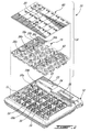
- Fig. 1 shows an example of a medication dispensing system 10.
- the system 10 has a console 12 with a receiving area 11 configured and adapted for receiving an insert 14 (shown received in the console 12).
- the insert 14 has tray 15 with an array of medication compartments 16a, 16b, 16n, each covered by a corresponding membrane 18a, 18b, 18n.
- the membranes 18a, 18b, 18n are designed to be hand-removable by the patient.
- Each one of the membranes 18n has a detection area 20 designed to make the presence and/or absence of the membrane 18n detectable by a detector (not shown) provided in the console 12, below the insert 14 when the insert 14 is received in the console 12.
- the console 12 also has a database (not shown) in which time periods at which the different compartments 16a, 16b, 16n should be dispensed can be stored, a real time clock (not shown), a display 26, and a visual alarm 22 and/or an audible alarm 24, to indicate when one of the stored time periods has been reached.
- the visual alarm 22 is provided below a window 23 in this example.
- the console also has a plurality of visual indicators (not shown), each associated with a corresponding compartment 16a, 16b, 16n, to visually indicate to the patient which specific one of the compartments 16a, 16b, 16n he should access.
- the insert 14 can be sold separately from the console 12.
- the receiving area 11 of the console 12 can be seen to have a plurality of medication compartment areas 28a, 28b, 28n.
- Each medication compartment area 28n has a main chamber 30 shaped and sized to receive a corresponding medication compartment 16n of the tray 15, a detector chamber 34 housing the respective detector, and an indicator chamber 32 housing the respective visual indicator.
- the detectors and indicators are connected on an electrical circuit board (not shown) provided below the chambers.
- the tray 15 has the medication compartments 16a, 16b, 16n, and further has a plurality of recesses 36a, 36b, 36n, each recess 36n being adapted to fit inside a corresponding detector chamber 34 in the console 12.
- the specific configuration of the console 12 and insert 14 can depart from the one illustrated.
- a pre-painted membrane sheet 40 having the plurality of membranes 18a, 18b, 18n corresponding to the medication compartments 16a, 16b, 16n pre-cut therein is used, and can be adhered as a whole to the surface 42 of the tray 15 after the tray 15 has been filled with the medication.
- Fig. 3A shows a cross-sectional view taken through a detector area 34.
- the tray 15 can be made of 0.015" thick see-through plastic
- the membrane 18, shown enlarged at Fig. 3B can have a 0.004" thick layer 19 of see-through polyester with a reflective coating 44, such as a light or metallic color paint for instance, and a shading coating 46, such as black or dark color paint for instance, above the reflective coating 44, in the detection area 20.
- an additional layer 48 can be present, such as colored paint for aesthetic or protective reasons, for instance.
- the detector 50 can include an emitter 52 which transmits a signal through the tray 15 and transparent polyester layer 19 of the membrane, which is then reflected on the reflective layer 44 and is sent back through the tray 15 to a receiver 54.
- an infrared LED is used as the emitter 52 and an infrared phototransistor is used as the receiver 54, respectively model QED 123 plastic infrared LED and model QSD 123 plastic silicon infrared phototransistor, both manufactured by FAIRCHILD SEMICONDUCTOR®, to be precise.
- the emitted signal can be a square signal modulated at a suitable frequency, for example.
- Fig. 3A also shows that the portion 56 of the tray 15 which is positioned above the emitter 52 is sloped at an angle ⁇ .
- the angle ⁇ can be selected to be approximately the Brewster angle, which represented about 32.5° in the instant example. This can help reduce the occurrence of parasite reflection by the tray 15 itself, and can help orienting remaining parasite reflection away from the receiver 54, so that the signal is not erroneously transmitted to the receiver 54 even when the membrane 18 is removed.
- an aperture (not shown) can be provided in the tray to allow transmission of the signal to and from the membrane, for example.
- a separator 58 is provided between the emitter 52 and the receptor 54 to reduce the likelihood of direct transmission therebetween.
- the walls 60, 62, 64 of the detector chamber 34 can be made infrared absorptive, such as by coating with a layer 66 of black paint, for example.
- the shading coating 46 (Fig. 3B ) on the membrane 18 helps reduce transmission of ambient radiation to the receptor 54, to reduce its possible effect on the signal.
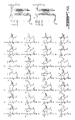
- Fig. 4 shows the electric circuit which is used in the system described above and illustrated
- Fig. 5 shows a block diagram showing various components the system can have.
- the console 12 can also include a pilot photodetector 68 which can be used as a reference by a controller 70 of the console 12 to obtain an indication of the ambient light or radiation in the console's immediate environment.
- the data from the pilot photodetector 68 can be used to help the controller 70 in interpreting variations or errors in the signals received by the detectors 50a, 50b, 50n.
- the tray 15 is filled with medication and the compartments 16a, 16b, 16n are covered by respective hand-removable membranes 18a, 18b, 18n. Each compartment thus acts as a receptacle for the medication.
- a database 72 of the console 12 is loaded with data concerning the time and date periods at which respective compartments 16a, 16b, 16n are to be dispensed to the patient.
- the insert 14 is placed in the receiving area 11 of the console 12.
- the controller 70 detects that one of the predetermined time periods is reached, an audible 24 and/or visual alarm 22 is activated. Different alarms can be used for different compartments, if desired, and the different alarms can be programmed to remain active for any desired amount of time. Further, the controller 70 can activate the specific visual indicator 74n corresponding to the specific compartment 16n to be dispensed.
- the controller 70 can periodically scan the detectors 50a, 50b, 50n to determine the status of the membranes 18a, 18b, 18n - i.e. if they are open or closed. When the specific compartment 16n to be dispensed is determined to be open, or the predetermined time period is passed, the visual alarm 22 and audible alarm 24 are stopped, and the information can be recorded in the database 72.
- the controller 70 can be programmed to sound an alarm if the wrong membrane is detected as being removed, or if a membrane is removed at the wrong time. Further, the controller 70 can be programmed to automatically detect when the insert 14 has been removed and changed by another insert by detecting that one or more of the membranes which were previously registered as being removed subsequently appear to be present.
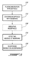
- Fig. 6 shows a flow chart of steps of an example of a method of dispensing medication.
- the medication is placed 110 in a receptacle or compartment, the receptacle is covered 112 by a membrane, the absence, or removal, of the membrane is detected 114, and the medication is registered 116 as dispensed.
- the system can indicate 118 which compartment is to be opened by the patient when the controller detects that the time to dispense the medication from one compartment is reached, upon accessing the database.
- registering the medication as dispensed can include storing the time and date at which the medication was dispensed in the database.
- the database can include one or more components to store different data, for example.
- a detector which has an emitter and receptor in combination with a membrane having reflective detection area
- a detector which has a photodetector can be used in combination with a membrane having a shaded detection area to detect removal of the membrane upon the increase in the photodetector output which follows the removal of the obstructing shaded area, for example.
- the detector can have a capacitive emitter which transmits an electric signal to an electrically conductive portion of the membrane, and a capacitive receiver which receives the electric signal from the electrically conductive portion of the membrane.
- Other detectors can be used as well.
- the transmission area is provided as a portion of the membrane, adjacent the detection area, without a shading layer of paint.
- the transmission area can be adjacent to the membrane, for example.
- the display can be used to transmit information to the user, such as the user's name and/or a time period for the insert, for example, to confirm to the user that the information programmed into the database effectively corresponds to the specific insert which has been positioned in the console.
- the display can also be associated with an alarm.
- the console can additionally include an interface, such as a button for recalling the visual indication of the medication compartment corresponding to the last alarm which was sound and a button to cancel an alarm, for example.
- the receiving area of the console has three chambers corresponding to each medication compartment of the insert.
- the exact configuration of alternate embodiments can depart from this example.
- it can be suitable to position the visual indicator directly below the medication chamber in alternate embodiments, or to use a detector which additionally acts as a visual indicator such as by using a color LED instead of an infrared LED, for example.
Landscapes
- Health & Medical Sciences (AREA)
- Engineering & Computer Science (AREA)
- Medical Informatics (AREA)
- Life Sciences & Earth Sciences (AREA)
- Animal Behavior & Ethology (AREA)
- General Health & Medical Sciences (AREA)
- Public Health (AREA)
- Veterinary Medicine (AREA)
- Medical Preparation Storing Or Oral Administration Devices (AREA)
- Medical Treatment And Welfare Office Work (AREA)
Description
- It is generally recognized in the medical field that medication is most efficient when taken at prescribed time periods. However, patients who are prescribed medication do not always take the medication at the prescribed times. This can be caused by several factors, such as confusion or forgetting, and is especially frequent in cases where patients are prescribed two or more different medications to be taken at different times of day.
- Many devices and methods have been proposed in the past to help remind patients to take their medication at specific times. Although satisfactory to a certain degree, there remained room for improvement.
- WO 2008/004212 discloses a method for dispensing medication in a receptacle, said receptacle having a bottom with a concave shape, directing the medication against a central aperture, in the path of a signal. The absence of the medication is detected by a travel time of the signal, a shorter travel time being associated to reflection by the medication, and a longer time associated to a reflection by a rigid batch covering the receptacle.
- This specification describes a medication dispensing system and method where the patient can have his personal console capable of receiving an insert having a tray with an array of medication compartments corresponding to respective times and dates at which the medication is prescribed to be taken. Membranes which can be hand-removed by the patient cover the respective compartments. The compartments can be filled and covered by a third party, such as a pharmacist, and the pharmacist can then set the specified times and dates at which the medication is to be taken in a programmable database of the console. When the console determines the time to dispense medication in a given one of the compartments has been reached, a visual and/or audible indicator can be triggered. In one embodiment, a visual indicator provided under the insert, and associated with the respective compartment, is lit, to visually indicate to the patient which compartment he should manually open. A corresponding detector provided under the insert can detect across the tray whether or not the membrane has been removed. Upon detecting removal of the membrane, the medication is registered as being dispensed in a database of the console, and the date and time of dispensing can be stored. When medication from the last compartment has been dispensed, the insert can be disposed of and replaced by another insert for another given time period. The data concerning the registered date and time of dispensing, which is indicative of whether the patient has taken the medication at the prescribed times or not, can be downloaded.
- In realizing the medication system and method disclosed herein, one challenge lied in conceiving a system which could accommodate removable and/or disposable tray inserts. Some known systems have permanent compartments, and the opening or closing of the compartment door can be detected by a mechanical switch. Such permanent compartments had a sanitary drawback. Using removable and/or disposable tray inserts can help having always a clean tray filled with the fresh medication. However, to be profitable, disposable tray inserts should have a sufficiently low cost. In this view, membranes were found more suitable as a closure for the compartments of the disposable insert than rigid doors, because membranes could be manufactured as sheets and adhered to the tray after filling with medication. Still with a view of low cost inserts in mind, compartment opening detection equipment should be made part of the console rather than part of the insert when possible. This resulted in incorporating detectors in the console below the tray, and led to the challenge of devising detectors and an overall system configuration which allowed detection of the removal of the membrane from below, across the tray. These and other challenges were addressed, as will be understood by persons skilled in the art in the light of this specification.
- In accordance with one aspect, there is provided a method for dispensing medication, the method comprising: placing said medication in a receptacle; covering said receptacle with a membrane; detecting an absence of said membrane over said receptacle when said membrane is removed and said medication is accessed, said detecting comprising emitting a signal beneath said membrane in a direction of said membrane, identifying said membrane as present when said signal is transmitted back by said membrane, and identifying said membrane as absent when said signal is not transmitted back by said membrane; and registering said medication as being dispensed when said absence has been detected.
- In accordance with another aspect, there is provided a medication dispensing system comprising a console having a receiving area configured and adapted for receiving an insert in a given position therein, the insert having a tray with an array of medication compartments and a plurality of hand-removable membranes each covering a respective one of the medication compartments, the console further comprising a plurality of membrane detectors, each detector associated with a corresponding medication compartment of the tray, each detector comprising both an emitter and a corresponding receiver, configured and adapted for transmitting a signal emitted by the emitter to the receiver via a corresponding one of the membranes when the insert is positioned in the receiving area, the console detecting that a given one of the membranes has been removed when the corresponding signal is not received by the corresponding receiver.
-
-
Fig. 1 is a perspective view of an example of a system for dispensing medication; -
Fig. 2 is an exploded view of the system ofFig. 1 ; -
Fig. 3A is a cross-sectional view taken alongcross-section lines 3A-3A ofFig. 1 ; -
Fig. 3B is a portion ofFig. 3A shown enlarged; -
Fig. 4 includesFigs. 4A ,4B , and4C , and is a schematic of the electric circuit of the system ofFig. 1 ; -
Fig. 5 is a bloc diagram of the system ofFig. 1 ; and -
Fig. 6 is a flow chart of a method of dispensing medication. -
Fig. 1 shows an example of amedication dispensing system 10. Thesystem 10 has aconsole 12 with areceiving area 11 configured and adapted for receiving an insert 14 (shown received in the console 12). Theinsert 14 has tray 15 with an array ofmedication compartments corresponding membrane membranes membranes 18n has adetection area 20 designed to make the presence and/or absence of themembrane 18n detectable by a detector (not shown) provided in theconsole 12, below theinsert 14 when theinsert 14 is received in theconsole 12. In this example, theconsole 12 also has a database (not shown) in which time periods at which thedifferent compartments display 26, and avisual alarm 22 and/or anaudible alarm 24, to indicate when one of the stored time periods has been reached. Thevisual alarm 22 is provided below awindow 23 in this example. The console also has a plurality of visual indicators (not shown), each associated with acorresponding compartment compartments insert 14 can be sold separately from theconsole 12. - In
Fig. 2 , thereceiving area 11 of theconsole 12 can be seen to have a plurality ofmedication compartment areas medication compartment area 28n has amain chamber 30 shaped and sized to receive acorresponding medication compartment 16n of thetray 15, adetector chamber 34 housing the respective detector, and anindicator chamber 32 housing the respective visual indicator. The detectors and indicators are connected on an electrical circuit board (not shown) provided below the chambers. Thetray 15 has themedication compartments recesses recess 36n being adapted to fit inside acorresponding detector chamber 34 in theconsole 12. In alternate embodiments, the specific configuration of theconsole 12 andinsert 14 can depart from the one illustrated. - In this example, a
pre-painted membrane sheet 40 having the plurality ofmembranes medication compartments surface 42 of thetray 15 after thetray 15 has been filled with the medication. - The following details are given for the purpose of illustration only, referring to
Fig. 3A , which shows a cross-sectional view taken through adetector area 34. In this example, thetray 15 can be made of 0.015" thick see-through plastic, and themembrane 18, shown enlarged atFig. 3B , can have a 0.004"thick layer 19 of see-through polyester with areflective coating 44, such as a light or metallic color paint for instance, and a shadingcoating 46, such as black or dark color paint for instance, above thereflective coating 44, in thedetection area 20. Optionally, anadditional layer 48 can be present, such as colored paint for aesthetic or protective reasons, for instance. Thedetector 50 can include anemitter 52 which transmits a signal through thetray 15 andtransparent polyester layer 19 of the membrane, which is then reflected on thereflective layer 44 and is sent back through thetray 15 to areceiver 54. In this example, an infrared LED is used as theemitter 52 and an infrared phototransistor is used as thereceiver 54, respectively model QED 123 plastic infrared LED and model QSD 123 plastic silicon infrared phototransistor, both manufactured by FAIRCHILD SEMICONDUCTOR®, to be precise. The emitted signal can be a square signal modulated at a suitable frequency, for example. -
Fig. 3A also shows that theportion 56 of thetray 15 which is positioned above theemitter 52 is sloped at an angle α. The angle α can be selected to be approximately the Brewster angle, which represented about 32.5° in the instant example. This can help reduce the occurrence of parasite reflection by thetray 15 itself, and can help orienting remaining parasite reflection away from thereceiver 54, so that the signal is not erroneously transmitted to thereceiver 54 even when themembrane 18 is removed. Alternately, an aperture (not shown) can be provided in the tray to allow transmission of the signal to and from the membrane, for example. Aseparator 58 is provided between theemitter 52 and thereceptor 54 to reduce the likelihood of direct transmission therebetween. To further help transmission of a clear signal, thewalls detector chamber 34 can be made infrared absorptive, such as by coating with alayer 66 of black paint, for example. The shading coating 46(Fig. 3B ) on themembrane 18 helps reduce transmission of ambient radiation to thereceptor 54, to reduce its possible effect on the signal. -
Fig. 4 shows the electric circuit which is used in the system described above and illustrated, whereas.Fig. 5 shows a block diagram showing various components the system can have. It is seen that theconsole 12 can also include apilot photodetector 68 which can be used as a reference by acontroller 70 of theconsole 12 to obtain an indication of the ambient light or radiation in the console's immediate environment. The data from thepilot photodetector 68 can be used to help thecontroller 70 in interpreting variations or errors in the signals received by thedetectors - Referring to
Figs. 1 and5 , in use, thetray 15 is filled with medication and thecompartments removable membranes database 72 of theconsole 12 is loaded with data concerning the time and date periods at whichrespective compartments insert 14 is placed in the receivingarea 11 of theconsole 12. When thecontroller 70 detects that one of the predetermined time periods is reached, an audible 24 and/orvisual alarm 22 is activated. Different alarms can be used for different compartments, if desired, and the different alarms can be programmed to remain active for any desired amount of time. Further, thecontroller 70 can activate the specificvisual indicator 74n corresponding to thespecific compartment 16n to be dispensed. - The
controller 70 can periodically scan thedetectors membranes specific compartment 16n to be dispensed is determined to be open, or the predetermined time period is passed, thevisual alarm 22 andaudible alarm 24 are stopped, and the information can be recorded in thedatabase 72. Thecontroller 70 can be programmed to sound an alarm if the wrong membrane is detected as being removed, or if a membrane is removed at the wrong time. Further, thecontroller 70 can be programmed to automatically detect when theinsert 14 has been removed and changed by another insert by detecting that one or more of the membranes which were previously registered as being removed subsequently appear to be present. -
Fig. 6 shows a flow chart of steps of an example of a method of dispensing medication. The medication is placed 110 in a receptacle or compartment, the receptacle is covered 112 by a membrane, the absence, or removal, of the membrane is detected 114, and the medication is registered 116 as dispensed. Optionally, the system can indicate 118 which compartment is to be opened by the patient when the controller detects that the time to dispense the medication from one compartment is reached, upon accessing the database. In one embodiment, registering the medication as dispensed can include storing the time and date at which the medication was dispensed in the database. The database can include one or more components to store different data, for example. - The example given above was provided for illustrative purposes. In other embodiments, different detectors and/or system configurations than the ones described above can be used. For example, instead of using a detector which has an emitter and receptor in combination with a membrane having reflective detection area, a detector which has a photodetector can be used in combination with a membrane having a shaded detection area to detect removal of the membrane upon the increase in the photodetector output which follows the removal of the obstructing shaded area, for example. In another embodiment, the detector can have a capacitive emitter which transmits an electric signal to an electrically conductive portion of the membrane, and a capacitive receiver which receives the electric signal from the electrically conductive portion of the membrane. Other detectors can be used as well.
- It can be useful that in the insert, there be provided a plurality of transmission areas associated with corresponding compartments, to be aligned with the corresponding visual indicators when the insert is in the given position in the receiving area of the console, to allow light from the visual indicators to be transmitted across the insert, to the patient. In the embodiment described above, the transmission area is provided as a portion of the membrane, adjacent the detection area, without a shading layer of paint. In alternate emdobiments, the transmission area can be adjacent to the membrane, for example.
- The display can be used to transmit information to the user, such as the user's name and/or a time period for the insert, for example, to confirm to the user that the information programmed into the database effectively corresponds to the specific insert which has been positioned in the console. The display can also be associated with an alarm. The console can additionally include an interface, such as a button for recalling the visual indication of the medication compartment corresponding to the last alarm which was sound and a button to cancel an alarm, for example.
- In the example described above and illustrated, the receiving area of the console has three chambers corresponding to each medication compartment of the insert. The exact configuration of alternate embodiments can depart from this example. For example, it can be suitable to position the visual indicator directly below the medication chamber in alternate embodiments, or to use a detector which additionally acts as a visual indicator such as by using a color LED instead of an infrared LED, for example.
- As can be seen therefore, the examples described above and illustrated are intended to be exemplary only. The scope is indicated by the appended claims.
Claims (14)
- A method for dispensing medication, the method comprising:placing said medication in a receptacle (16a, 16b, 16n);covering said receptacle with a membrane (18a, 18b, 18n);detecting an absence of said membrane over said receptacle when said membrane is removed and said medication is accessed, said detecting comprising emitting a signal beneath said membrane, identifying said membrane as present when said signal is reflected back by said membrane, and identifying said membrane as absent when said signal is not reflected back; andregistering said medication as being dispensed when said absence has been detected.
- A method as claimed in claim 1, wherein the signal is infrared - light-based.
- A method as claimed in claim 1, wherein said emitting a signal comprises emitting said signal intermittently.
- A method as claimed in claim 1, wherein said registering said medication as being dispensed comprises registering a time at which said medication was dispensed.
- A method as claimed in claim 1, wherein said emitting a signal comprises emitting said signal beneath said receptacle.
- A method as claimed in claim 1, further comprising maintaining a log identifying a time at which said medication is intended to be dispensed, and alerting a user when said time occurs.
- A method as claimed in claim 6, further comprising testing for a presence of said membrane after said time has passed and alerting said user if said membrane is detected as present.
- A medication dispensing system (10) comprising a console (12) having a receiving area (11) configured and adapted for receiving an insert (14) in a given position therein, the insert having a tray (15) with an array of medication compartments (16a, 16b, 16n),
the system being characterized in that it further comprises a plurality of hand-removable membranes (18a, 18b, 18n) each covering one of the medication compartments respectively, the console (12) further comprising a plurality of membrane detectors (50a, 50b, 50n), each detector associated with a corresponding medication compartment (16a, 16b, 16n) of the tray and being capable of detecting if the corresponding membrane has been removed when the insert (14) is positioned in the receiving area (11) wherein each one of the hand-removable membranes has a reflecting area, and each one of the detectors comprises a receiver (54) and an emitter (52), configured and adapted for transmitting a signal emitted by the emitter to the reflecting area across the tray, and the reflecting area reflecting the signal back across the tray to the receiver when the insert is positioned in the receiving area, the signal not being transmitted to the receiver when the corresponding membrane has been removed. - The system (10) of claim 8 wherein each one of the hand-removable membranes (18a, 18b, 18n) further has a shading layer (46) covering the reflecting area.
- The system (10) of claim 8 wherein the tray (15) has a plurality of recesses (36a, 36b, 36n) positioned above corresponding detectors when the insert (14) is positioned in the receiving area, each recesses comprising a sloping portion configured and adapted for orienting parasite reflections away from the receiver.
- The system (10) of claim 8 wherein the tray (15) has a plurality of recesses positioned above corresponding detectors when the insert is positioned in the receiving area, each recesses comprising a sloping portion at an angle approximately equal to the Brewster angle for the emitted signal.
- The system (10) of claim 8 wherein each one of the hand-removable membranes (18a, 18b, 18n) has an electrically conductive area, the receiver (54) and emitter (52) being a capacitive receiver and a capacitive emitter, respectively, configured and adapted for transmitting a signal emitted by the emitter by capacitance to the electrically conductive area across the tray, and the electrically conductive area transmitting the signal back across the tray (15) by capacitance to the receiver when the insert is positioned in the receiving area.
- The system (10) of claim 8 further comprising a database (72), and a controller (70) connected to the membrane detectors (50a, 50b, 50n) and configured for registering any one of the medication compartments as dispensed in the database when the corresponding membrane is detected as being removed.
- The system (10) of claim 8 wherein the console (12) further comprises a plurality of indicators (74n), each indicator positioned below a corresponding medication compartment (16a, 16b, 16n) of the tray (15), configured and adapted for visually indicating any corresponding one of the medication compartments visually to a user.
Applications Claiming Priority (2)
| Application Number | Priority Date | Filing Date | Title |
|---|---|---|---|
| CA2575125 | 2007-01-19 | ||
| PCT/CA2008/000107 WO2008086628A1 (en) | 2007-01-19 | 2008-01-21 | Medication dispensing system and method |
Publications (4)
| Publication Number | Publication Date |
|---|---|
| EP2111212A1 EP2111212A1 (en) | 2009-10-28 |
| EP2111212A4 EP2111212A4 (en) | 2011-12-14 |
| EP2111212B1 true EP2111212B1 (en) | 2013-04-17 |
| EP2111212B9 EP2111212B9 (en) | 2014-10-29 |
Family
ID=39635616
Family Applications (1)
| Application Number | Title | Priority Date | Filing Date |
|---|---|---|---|
| EP20080706254 Not-in-force EP2111212B9 (en) | 2007-01-19 | 2008-01-21 | Medication dispensing system and method |
Country Status (7)
| Country | Link |
|---|---|
| US (1) | US8214077B2 (en) |
| EP (1) | EP2111212B9 (en) |
| CA (1) | CA2665733C (en) |
| DK (1) | DK2111212T3 (en) |
| ES (1) | ES2421636T3 (en) |
| PT (1) | PT2111212E (en) |
| WO (1) | WO2008086628A1 (en) |
Families Citing this family (19)
| Publication number | Priority date | Publication date | Assignee | Title |
|---|---|---|---|---|
| GB2463054A (en) * | 2008-08-30 | 2010-03-03 | Adavanced Telecare Solutions L | Device for monitoring the removal of items placed in compartments of a blister package using ambient light |
| US8744620B2 (en) | 2008-10-31 | 2014-06-03 | Medminder Systems, Inc. | Interactive medication dispensing system with locking compartments |
| US9211233B2 (en) | 2008-10-31 | 2015-12-15 | Medminder Systems, Inc. | Interactive medication dispensing system |
| US8818740B2 (en) * | 2010-02-17 | 2014-08-26 | Pentair Thermal Management Llc | Sensor-powered wireless cable leak detection |
| US8749359B1 (en) * | 2010-12-28 | 2014-06-10 | Ruta Wilson | Tablet holder with alert system |
| GB2489921B (en) * | 2011-04-06 | 2013-03-27 | Future Technology Uk Ltd | Flexible seals with integral display panels and containers including such seals |
| WO2013025520A2 (en) * | 2011-08-12 | 2013-02-21 | Medminder Systems, Inc. | Interactive medication dispensing system |
| FI124415B (en) * | 2011-12-02 | 2014-08-29 | Newico Oy | Apparatus for dispensing drugs, vitamins and / or samples |
| AU2012397580A1 (en) * | 2012-12-19 | 2015-06-25 | Caroline Blochet | Pill dispensing system for monitoring compliant receipt of pills by a patient |
| US9278053B2 (en) | 2013-11-14 | 2016-03-08 | Xerox Corporation | Apparatus and system with pre-loaded cassette for dispensing multiple medications and methods therefore |
| US9532666B2 (en) * | 2014-06-24 | 2017-01-03 | Apex Industrial Technologies Llc | Modular storage system |
| US9757305B2 (en) * | 2014-11-26 | 2017-09-12 | RxAdvance Corporation | Medication organizer tray apparatus |
| FR3031086B1 (en) * | 2014-12-31 | 2017-01-27 | Com4 | DEVICE FOR SECURELY RECOVERING THE TABLETS CONTAINED IN AN ALVEOL OF A PILULAR CLOSED BY A MEMBRANE THAT CAN BE PERFORATED. |
| JP2018504210A (en) | 2015-01-21 | 2018-02-15 | マイラン・インコーポレイテッドMylan Inc. | Pharmaceutical packaging and administration planning system |
| US10759591B2 (en) | 2017-07-26 | 2020-09-01 | Oes, Inc. | Dosage monitoring based on signal presence |
| US11160727B2 (en) | 2019-04-25 | 2021-11-02 | Apothecary Products, Llc | Lockable medicine container and methods |
| USD976573S1 (en) | 2019-04-25 | 2023-01-31 | Apothecary Products, Llc | Medicine container |
| US11759397B2 (en) | 2020-10-07 | 2023-09-19 | S&SX-ray Products, Inc. | Medication dispensing arrangement without scanning |
| CA3173779C (en) * | 2021-10-20 | 2024-06-25 | 9155-0020 Quebec Inc. | Tray system and method for filling pills into blister packs |
Family Cites Families (51)
| Publication number | Priority date | Publication date | Assignee | Title |
|---|---|---|---|---|
| US262190A (en) | 1882-08-01 | Handle attachment for tilting chairs | ||
| US391156A (en) | 1888-10-16 | Ivee johnson and andrew fyrberg | ||
| US296589A (en) | 1884-04-08 | Neck-yoke | ||
| US2014851A (en) * | 1932-11-01 | 1935-09-17 | Kronenberger Ferdinand | Fiber cushion holder for eggs |
| DE3335301C2 (en) * | 1983-06-25 | 1985-05-02 | Udo 8500 Nürnberg Simon | Drug container |
| US4768177A (en) * | 1984-07-06 | 1988-08-30 | Kehr Bruce A | Method of and apparatus for alerting a patient to take medication |
| US4695954A (en) * | 1984-10-31 | 1987-09-22 | Rose Robert J | Modular medication dispensing system and apparatus utilizing portable memory device |
| US4617557A (en) * | 1984-11-08 | 1986-10-14 | National Patent Development Corporation | Medication compliance aid for unit dose packaging |
| US4640560A (en) * | 1984-12-17 | 1987-02-03 | Blum Richard S | Pill dispenser |
| US4682299A (en) * | 1985-02-19 | 1987-07-21 | Kenneth B. McIntosh | Medication clock |
| DE3518531A1 (en) * | 1985-05-23 | 1986-11-27 | Dieter Dipl.-Phys. Dr. 8500 Nürnberg Hafner | Device for the storage and time-prompted taking of medicaments |
| US4717042A (en) * | 1986-05-28 | 1988-01-05 | Pyxis Corporation | Medicine dispenser for home health care |
| SE463348B (en) * | 1988-03-29 | 1990-11-12 | Compumed Ab | DEVICE FOR SIGNAL OF ADMINISTRATION OF MEDICINAL TABLETS |
| NZ231236A (en) * | 1988-11-11 | 1992-07-28 | Manrex Australia Pty Ltd | Assembly for blister package |
| US5020037A (en) * | 1989-01-26 | 1991-05-28 | Raven Malcolm R | Alarm pill box |
| US5014851A (en) * | 1989-06-16 | 1991-05-14 | Multi-Comp, Inc. | Package assembly for dispensing pharmaceutical medications and method of manufacturing the same |
| US5200891A (en) * | 1990-01-17 | 1993-04-06 | Bruce A. Kehr | Electronic medication dispensing method |
| US5408443A (en) * | 1992-08-19 | 1995-04-18 | Polypharm Corp. | Programmable medication dispensing system |
| US5412372A (en) * | 1992-09-21 | 1995-05-02 | Medical Microsystems, Inc. | Article dispenser for monitoring dispensing times |
| US5392951A (en) * | 1993-05-20 | 1995-02-28 | Lionville Systems, Inc. | Drawer operating system |
| SE512207C2 (en) * | 1993-11-26 | 2000-02-14 | Meditelligence Ab | Drug storage device |
| US5745366A (en) * | 1994-07-14 | 1998-04-28 | Omnicell Technologies, Inc. | Pharmaceutical dispensing device and methods |
| US6760643B2 (en) * | 1994-10-11 | 2004-07-06 | Omnicell, Inc. | Methods and apparatus for dispensing items |
| US6640159B2 (en) * | 1996-12-05 | 2003-10-28 | Omnicell Technologies, Inc. | Replacement liner and methods for a dispensing device |
| US6449218B1 (en) * | 1997-10-10 | 2002-09-10 | Alex Lluch | Medicine storage and reminder device |
| US5954225A (en) * | 1998-03-26 | 1999-09-21 | Powe; Patricia S. | Pill dispenser |
| US20030230590A1 (en) * | 1998-06-25 | 2003-12-18 | Gilmore Janice F. | Automatic medicament dispenser system |
| US6151536A (en) * | 1998-09-28 | 2000-11-21 | Omnicell.Com | Dispensing system and methods |
| GB2344194A (en) * | 1998-11-25 | 2000-05-31 | Kevin Doughty | Medication reminder device |
| US6169707B1 (en) * | 1998-11-30 | 2001-01-02 | Douglas A. Newland | Medication storage and reminder device |
| US6294999B1 (en) * | 1999-12-29 | 2001-09-25 | Becton, Dickinson And Company | Systems and methods for monitoring patient compliance with medication regimens |
| CA2408641C (en) * | 2000-06-05 | 2008-04-15 | Manrex Pty. Ltd. | Medication dispenser |
| CA2311622A1 (en) * | 2000-06-15 | 2001-12-15 | Moussa Hoummady | Sub-nanoliter liquid drop dispensing system and method therefor |
| US6625518B2 (en) * | 2000-06-22 | 2003-09-23 | Csem Centre Suisse D'electronique Et De Microtechnique Sa | Method supporting administration of a prescribed drug and implementing said method |
| US6411567B1 (en) * | 2000-07-07 | 2002-06-25 | Mark A. Niemiec | Drug delivery management system |
| US6801123B2 (en) * | 2001-09-28 | 2004-10-05 | Tony George Brakus | Electronic organizer and storage device |
| AU2002348242A1 (en) * | 2001-11-30 | 2003-06-17 | Becton, Dickinson And Company | Medication adherence system |
| US6644496B1 (en) * | 2001-12-14 | 2003-11-11 | Anthony J. Ambrosio | Medication dispensing system |
| EP1474090B1 (en) * | 2002-02-14 | 2012-04-11 | Udo Simon | Device for detecting the removal of a product from a packing system by an electronic unit |
| JP2005518871A (en) * | 2002-03-07 | 2005-06-30 | バング・オ・オルフセン・メディコム・アクティーゼルスカブ | Medical dispenser, blister card used in dispenser and method of dispensing medication |
| JP5022565B2 (en) * | 2002-04-29 | 2012-09-12 | グラクソ グループ リミテッド | Drug dispenser |
| AU2002951072A0 (en) * | 2002-08-28 | 2002-09-12 | Manrex Pty. Ltd | Device for ejecting blister tablets |
| US7451876B2 (en) * | 2004-04-24 | 2008-11-18 | Inrange Systems, Inc. | Universal medication carrier |
| CA2515815C (en) * | 2004-08-25 | 2013-05-14 | Richard Weisbeck | Portable pill crusher |
| CA2493410C (en) * | 2005-01-20 | 2016-09-27 | Intelligent Devices Inc. | Assembly, production and quality assurance processes respecting electronic compliance monitor (ecm) tags |
| US7481331B2 (en) * | 2005-09-09 | 2009-01-27 | Manrex Limited | Dispensing container for a blister pack of medications |
| US7213822B1 (en) * | 2005-10-27 | 2007-05-08 | Manrex Limited | Medication cart with height adjustment |
| CA2635476A1 (en) * | 2005-12-12 | 2007-06-21 | International Paper Company | Momentary switch integrated in packaging of an article |
| US7922037B2 (en) * | 2006-02-10 | 2011-04-12 | Tosho Inc. | Device for manually dispensing medications |
| IL176712A0 (en) * | 2006-07-05 | 2007-10-31 | Michael Cohen Alloro | Medication dispenser |
| US20080054007A1 (en) * | 2006-07-27 | 2008-03-06 | Jack Mador | System and method for distributing medication and monitoring medication protocol compliance |
-
2008
- 2008-01-21 WO PCT/CA2008/000107 patent/WO2008086628A1/en not_active Ceased
- 2008-01-21 CA CA 2665733 patent/CA2665733C/en active Active
- 2008-01-21 EP EP20080706254 patent/EP2111212B9/en not_active Not-in-force
- 2008-01-21 DK DK08706254T patent/DK2111212T3/en active
- 2008-01-21 PT PT87062543T patent/PT2111212E/en unknown
- 2008-01-21 US US12/448,327 patent/US8214077B2/en not_active Expired - Fee Related
- 2008-01-21 ES ES08706254T patent/ES2421636T3/en active Active
Also Published As
| Publication number | Publication date |
|---|---|
| US8214077B2 (en) | 2012-07-03 |
| US20100049361A1 (en) | 2010-02-25 |
| EP2111212A1 (en) | 2009-10-28 |
| WO2008086628A1 (en) | 2008-07-24 |
| ES2421636T9 (en) | 2015-01-21 |
| EP2111212A4 (en) | 2011-12-14 |
| CA2665733A1 (en) | 2008-07-24 |
| CA2665733C (en) | 2010-02-02 |
| PT2111212E (en) | 2013-07-18 |
| DK2111212T3 (en) | 2013-07-22 |
| ES2421636T3 (en) | 2013-09-04 |
| EP2111212B9 (en) | 2014-10-29 |
Similar Documents
| Publication | Publication Date | Title |
|---|---|---|
| EP2111212B9 (en) | Medication dispensing system and method | |
| US9814339B2 (en) | Device to measure and monitor drinking and eating having a cup holder with a digital camera | |
| US7359765B2 (en) | Electronic pill dispenser | |
| EP0445154B1 (en) | Drug dispenser having means for detecting dispensing events | |
| US8279063B2 (en) | Personnel location and monitoring system and method for enclosed facilities | |
| US9233051B2 (en) | Blister holder provided with means designed to detect the number of extracted products from the blister and with GSM/GPRS communication means to remotely dialogue with a control center | |
| US6625518B2 (en) | Method supporting administration of a prescribed drug and implementing said method | |
| US5042685A (en) | Dispensing having a compartment for detecting and counting the dispensed objects especially adapted for dispensing medication and method of using the same | |
| EP2277422B1 (en) | Dispenser with palm reader | |
| US20100236973A1 (en) | Container For a Blister Package | |
| US6615107B2 (en) | Automated system and method for dispensing medications for low visions elderly and blind individuals | |
| WO2012013723A1 (en) | Pharmaceutical product dispenser | |
| US20100207767A1 (en) | Portable hand wash monitoring system and method | |
| US20230404856A1 (en) | Device, System and Method for Managing and Monitoring Medication of a Patient | |
| US12488889B2 (en) | Systems and methods for monitoring sharps levels in secured sharps containers | |
| JP2018068743A (en) | Medication management device and system thereof | |
| WO1991004726A1 (en) | A method and apparatus for facilitating medication | |
| JP2002291844A (en) | Medicine container | |
| JP2018094440A (en) | Medication management system and medication management device | |
| EP3934603B1 (en) | Device for monitoring the medication of a patient | |
| JP6288779B2 (en) | Medication management system and medication management device | |
| GB2233317A (en) | Timed medication dispensers | |
| EP3243414A1 (en) | Arrangement and method for detecting resource usage in a dispenser, dispenser, and system and method for monitoring resource usage in at least one dispenser | |
| US20250064682A1 (en) | An intelligent digital medicine storage and reminder device | |
| ES3002241T3 (en) | Medical supplies cabinet |
Legal Events
| Date | Code | Title | Description |
|---|---|---|---|
| PUAI | Public reference made under article 153(3) epc to a published international application that has entered the european phase |
Free format text: ORIGINAL CODE: 0009012 |
|
| 17P | Request for examination filed |
Effective date: 20090819 |
|
| AK | Designated contracting states |
Kind code of ref document: A1 Designated state(s): AT BE BG CH CY CZ DE DK EE ES FI FR GB GR HR HU IE IS IT LI LT LU LV MC MT NL NO PL PT RO SE SI SK TR |
|
| DAX | Request for extension of the european patent (deleted) | ||
| A4 | Supplementary search report drawn up and despatched |
Effective date: 20111114 |
|
| RIC1 | Information provided on ipc code assigned before grant |
Ipc: A61J 7/00 20060101AFI20111108BHEP Ipc: A61J 7/04 20060101ALI20111108BHEP |
|
| 17Q | First examination report despatched |
Effective date: 20120612 |
|
| GRAP | Despatch of communication of intention to grant a patent |
Free format text: ORIGINAL CODE: EPIDOSNIGR1 |
|
| GRAS | Grant fee paid |
Free format text: ORIGINAL CODE: EPIDOSNIGR3 |
|
| GRAA | (expected) grant |
Free format text: ORIGINAL CODE: 0009210 |
|
| AK | Designated contracting states |
Kind code of ref document: B1 Designated state(s): AT BE BG CH CY CZ DE DK EE ES FI FR GB GR HR HU IE IS IT LI LT LU LV MC MT NL NO PL PT RO SE SI SK TR |
|
| REG | Reference to a national code |
Ref country code: GB Ref legal event code: FG4D |
|
| REG | Reference to a national code |
Ref country code: CH Ref legal event code: EP |
|
| REG | Reference to a national code |
Ref country code: IE Ref legal event code: FG4D |
|
| REG | Reference to a national code |
Ref country code: AT Ref legal event code: REF Ref document number: 606784 Country of ref document: AT Kind code of ref document: T Effective date: 20130515 |
|
| REG | Reference to a national code |
Ref country code: DE Ref legal event code: R096 Ref document number: 602008023869 Country of ref document: DE Effective date: 20130613 |
|
| REG | Reference to a national code |
Ref country code: PT Ref legal event code: SC4A Free format text: AVAILABILITY OF NATIONAL TRANSLATION Effective date: 20130712 |
|
| REG | Reference to a national code |
Ref country code: DK Ref legal event code: T3 |
|
| REG | Reference to a national code |
Ref country code: SE Ref legal event code: TRGR |
|
| REG | Reference to a national code |
Ref country code: NO Ref legal event code: T2 Effective date: 20130417 |
|
| REG | Reference to a national code |
Ref country code: ES Ref legal event code: FG2A Ref document number: 2421636 Country of ref document: ES Kind code of ref document: T3 Effective date: 20130904 |
|
| REG | Reference to a national code |
Ref country code: AT Ref legal event code: MK05 Ref document number: 606784 Country of ref document: AT Kind code of ref document: T Effective date: 20130417 |
|
| REG | Reference to a national code |
Ref country code: NL Ref legal event code: T3 |
|
| REG | Reference to a national code |
Ref country code: LT Ref legal event code: MG4D |
|
| PG25 | Lapsed in a contracting state [announced via postgrant information from national office to epo] |
Ref country code: IS Free format text: LAPSE BECAUSE OF FAILURE TO SUBMIT A TRANSLATION OF THE DESCRIPTION OR TO PAY THE FEE WITHIN THE PRESCRIBED TIME-LIMIT Effective date: 20130817 Ref country code: LT Free format text: LAPSE BECAUSE OF FAILURE TO SUBMIT A TRANSLATION OF THE DESCRIPTION OR TO PAY THE FEE WITHIN THE PRESCRIBED TIME-LIMIT Effective date: 20130417 Ref country code: GR Free format text: LAPSE BECAUSE OF FAILURE TO SUBMIT A TRANSLATION OF THE DESCRIPTION OR TO PAY THE FEE WITHIN THE PRESCRIBED TIME-LIMIT Effective date: 20130718 Ref country code: AT Free format text: LAPSE BECAUSE OF FAILURE TO SUBMIT A TRANSLATION OF THE DESCRIPTION OR TO PAY THE FEE WITHIN THE PRESCRIBED TIME-LIMIT Effective date: 20130417 Ref country code: SI Free format text: LAPSE BECAUSE OF FAILURE TO SUBMIT A TRANSLATION OF THE DESCRIPTION OR TO PAY THE FEE WITHIN THE PRESCRIBED TIME-LIMIT Effective date: 20130417 |
|
| PG25 | Lapsed in a contracting state [announced via postgrant information from national office to epo] |
Ref country code: BG Free format text: LAPSE BECAUSE OF FAILURE TO SUBMIT A TRANSLATION OF THE DESCRIPTION OR TO PAY THE FEE WITHIN THE PRESCRIBED TIME-LIMIT Effective date: 20130717 Ref country code: HR Free format text: LAPSE BECAUSE OF FAILURE TO SUBMIT A TRANSLATION OF THE DESCRIPTION OR TO PAY THE FEE WITHIN THE PRESCRIBED TIME-LIMIT Effective date: 20130417 Ref country code: PL Free format text: LAPSE BECAUSE OF FAILURE TO SUBMIT A TRANSLATION OF THE DESCRIPTION OR TO PAY THE FEE WITHIN THE PRESCRIBED TIME-LIMIT Effective date: 20130417 Ref country code: LV Free format text: LAPSE BECAUSE OF FAILURE TO SUBMIT A TRANSLATION OF THE DESCRIPTION OR TO PAY THE FEE WITHIN THE PRESCRIBED TIME-LIMIT Effective date: 20130417 Ref country code: CY Free format text: LAPSE BECAUSE OF FAILURE TO SUBMIT A TRANSLATION OF THE DESCRIPTION OR TO PAY THE FEE WITHIN THE PRESCRIBED TIME-LIMIT Effective date: 20130417 |
|
| PG25 | Lapsed in a contracting state [announced via postgrant information from national office to epo] |
Ref country code: SK Free format text: LAPSE BECAUSE OF FAILURE TO SUBMIT A TRANSLATION OF THE DESCRIPTION OR TO PAY THE FEE WITHIN THE PRESCRIBED TIME-LIMIT Effective date: 20130417 Ref country code: CZ Free format text: LAPSE BECAUSE OF FAILURE TO SUBMIT A TRANSLATION OF THE DESCRIPTION OR TO PAY THE FEE WITHIN THE PRESCRIBED TIME-LIMIT Effective date: 20130417 Ref country code: EE Free format text: LAPSE BECAUSE OF FAILURE TO SUBMIT A TRANSLATION OF THE DESCRIPTION OR TO PAY THE FEE WITHIN THE PRESCRIBED TIME-LIMIT Effective date: 20130417 |
|
| PLBE | No opposition filed within time limit |
Free format text: ORIGINAL CODE: 0009261 |
|
| STAA | Information on the status of an ep patent application or granted ep patent |
Free format text: STATUS: NO OPPOSITION FILED WITHIN TIME LIMIT |
|
| PG25 | Lapsed in a contracting state [announced via postgrant information from national office to epo] |
Ref country code: RO Free format text: LAPSE BECAUSE OF FAILURE TO SUBMIT A TRANSLATION OF THE DESCRIPTION OR TO PAY THE FEE WITHIN THE PRESCRIBED TIME-LIMIT Effective date: 20130417 |
|
| 26N | No opposition filed |
Effective date: 20140120 |
|
| REG | Reference to a national code |
Ref country code: DE Ref legal event code: R097 Ref document number: 602008023869 Country of ref document: DE Effective date: 20140120 |
|
| PG25 | Lapsed in a contracting state [announced via postgrant information from national office to epo] |
Ref country code: MC Free format text: LAPSE BECAUSE OF FAILURE TO SUBMIT A TRANSLATION OF THE DESCRIPTION OR TO PAY THE FEE WITHIN THE PRESCRIBED TIME-LIMIT Effective date: 20130417 |
|
| REG | Reference to a national code |
Ref country code: IE Ref legal event code: MM4A |
|
| PG25 | Lapsed in a contracting state [announced via postgrant information from national office to epo] |
Ref country code: IE Free format text: LAPSE BECAUSE OF NON-PAYMENT OF DUE FEES Effective date: 20140121 |
|
| REG | Reference to a national code |
Ref country code: FR Ref legal event code: PLFP Year of fee payment: 9 |
|
| PG25 | Lapsed in a contracting state [announced via postgrant information from national office to epo] |
Ref country code: MT Free format text: LAPSE BECAUSE OF FAILURE TO SUBMIT A TRANSLATION OF THE DESCRIPTION OR TO PAY THE FEE WITHIN THE PRESCRIBED TIME-LIMIT Effective date: 20130417 |
|
| PG25 | Lapsed in a contracting state [announced via postgrant information from national office to epo] |
Ref country code: TR Free format text: LAPSE BECAUSE OF FAILURE TO SUBMIT A TRANSLATION OF THE DESCRIPTION OR TO PAY THE FEE WITHIN THE PRESCRIBED TIME-LIMIT Effective date: 20130417 Ref country code: HU Free format text: LAPSE BECAUSE OF FAILURE TO SUBMIT A TRANSLATION OF THE DESCRIPTION OR TO PAY THE FEE WITHIN THE PRESCRIBED TIME-LIMIT; INVALID AB INITIO Effective date: 20080121 |
|
| REG | Reference to a national code |
Ref country code: FR Ref legal event code: PLFP Year of fee payment: 10 |
|
| REG | Reference to a national code |
Ref country code: FR Ref legal event code: PLFP Year of fee payment: 11 |
|
| PGFP | Annual fee paid to national office [announced via postgrant information from national office to epo] |
Ref country code: LU Payment date: 20190122 Year of fee payment: 12 |
|
| PGFP | Annual fee paid to national office [announced via postgrant information from national office to epo] |
Ref country code: FI Payment date: 20190122 Year of fee payment: 12 Ref country code: IT Payment date: 20190124 Year of fee payment: 12 Ref country code: NO Payment date: 20190123 Year of fee payment: 12 Ref country code: DE Payment date: 20190123 Year of fee payment: 12 Ref country code: CH Payment date: 20190123 Year of fee payment: 12 Ref country code: GB Payment date: 20190121 Year of fee payment: 12 Ref country code: FR Payment date: 20190124 Year of fee payment: 12 Ref country code: ES Payment date: 20190226 Year of fee payment: 12 Ref country code: NL Payment date: 20190121 Year of fee payment: 12 |
|
| PGFP | Annual fee paid to national office [announced via postgrant information from national office to epo] |
Ref country code: BE Payment date: 20190121 Year of fee payment: 12 Ref country code: SE Payment date: 20190121 Year of fee payment: 12 Ref country code: DK Payment date: 20190123 Year of fee payment: 12 |
|
| PGFP | Annual fee paid to national office [announced via postgrant information from national office to epo] |
Ref country code: PT Payment date: 20190115 Year of fee payment: 12 |
|
| REG | Reference to a national code |
Ref country code: DE Ref legal event code: R119 Ref document number: 602008023869 Country of ref document: DE |
|
| REG | Reference to a national code |
Ref country code: FI Ref legal event code: MAE |
|
| REG | Reference to a national code |
Ref country code: NO Ref legal event code: MMEP |
|
| REG | Reference to a national code |
Ref country code: DK Ref legal event code: EBP Effective date: 20200131 Ref country code: CH Ref legal event code: PL |
|
| REG | Reference to a national code |
Ref country code: SE Ref legal event code: EUG |
|
| REG | Reference to a national code |
Ref country code: NL Ref legal event code: MM Effective date: 20200201 |
|
| GBPC | Gb: european patent ceased through non-payment of renewal fee |
Effective date: 20200121 |
|
| REG | Reference to a national code |
Ref country code: SE Ref legal event code: EUG |
|
| REG | Reference to a national code |
Ref country code: BE Ref legal event code: MM Effective date: 20200131 |
|
| PG25 | Lapsed in a contracting state [announced via postgrant information from national office to epo] |
Ref country code: LU Free format text: LAPSE BECAUSE OF NON-PAYMENT OF DUE FEES Effective date: 20200121 Ref country code: SE Free format text: LAPSE BECAUSE OF NON-PAYMENT OF DUE FEES Effective date: 20200122 Ref country code: FR Free format text: LAPSE BECAUSE OF NON-PAYMENT OF DUE FEES Effective date: 20200131 Ref country code: FI Free format text: LAPSE BECAUSE OF NON-PAYMENT OF DUE FEES Effective date: 20200121 Ref country code: NO Free format text: LAPSE BECAUSE OF NON-PAYMENT OF DUE FEES Effective date: 20200131 Ref country code: NL Free format text: LAPSE BECAUSE OF NON-PAYMENT OF DUE FEES Effective date: 20200201 Ref country code: PT Free format text: LAPSE BECAUSE OF NON-PAYMENT OF DUE FEES Effective date: 20200821 Ref country code: DE Free format text: LAPSE BECAUSE OF NON-PAYMENT OF DUE FEES Effective date: 20200801 Ref country code: GB Free format text: LAPSE BECAUSE OF NON-PAYMENT OF DUE FEES Effective date: 20200121 |
|
| PG25 | Lapsed in a contracting state [announced via postgrant information from national office to epo] |
Ref country code: BE Free format text: LAPSE BECAUSE OF NON-PAYMENT OF DUE FEES Effective date: 20200131 Ref country code: LI Free format text: LAPSE BECAUSE OF NON-PAYMENT OF DUE FEES Effective date: 20200131 Ref country code: CH Free format text: LAPSE BECAUSE OF NON-PAYMENT OF DUE FEES Effective date: 20200131 |
|
| PG25 | Lapsed in a contracting state [announced via postgrant information from national office to epo] |
Ref country code: DK Free format text: LAPSE BECAUSE OF NON-PAYMENT OF DUE FEES Effective date: 20200131 Ref country code: IT Free format text: LAPSE BECAUSE OF NON-PAYMENT OF DUE FEES Effective date: 20200121 |
|
| REG | Reference to a national code |
Ref country code: ES Ref legal event code: FD2A Effective date: 20210604 |
|
| PG25 | Lapsed in a contracting state [announced via postgrant information from national office to epo] |
Ref country code: ES Free format text: LAPSE BECAUSE OF NON-PAYMENT OF DUE FEES Effective date: 20200122 |