EP2110917A2 - Verfahren zur Einstellung einer Erdfehler-Auslöseeinheit mit einer definierten Auslösefunktion zum Erdfehlerschutz - Google Patents
Verfahren zur Einstellung einer Erdfehler-Auslöseeinheit mit einer definierten Auslösefunktion zum Erdfehlerschutz Download PDFInfo
- Publication number
- EP2110917A2 EP2110917A2 EP09157332A EP09157332A EP2110917A2 EP 2110917 A2 EP2110917 A2 EP 2110917A2 EP 09157332 A EP09157332 A EP 09157332A EP 09157332 A EP09157332 A EP 09157332A EP 2110917 A2 EP2110917 A2 EP 2110917A2
- Authority
- EP
- European Patent Office
- Prior art keywords
- trip
- ground fault
- functions
- unit
- function
- Prior art date
- Legal status (The legal status is an assumption and is not a legal conclusion. Google has not performed a legal analysis and makes no representation as to the accuracy of the status listed.)
- Withdrawn
Links
Images


Classifications
-
- H—ELECTRICITY
- H02—GENERATION; CONVERSION OR DISTRIBUTION OF ELECTRIC POWER
- H02H—EMERGENCY PROTECTIVE CIRCUIT ARRANGEMENTS
- H02H3/00—Emergency protective circuit arrangements for automatic disconnection directly responsive to an undesired change from normal electric working condition with or without subsequent reconnection ; integrated protection
- H02H3/08—Emergency protective circuit arrangements for automatic disconnection directly responsive to an undesired change from normal electric working condition with or without subsequent reconnection ; integrated protection responsive to excess current
- H02H3/093—Emergency protective circuit arrangements for automatic disconnection directly responsive to an undesired change from normal electric working condition with or without subsequent reconnection ; integrated protection responsive to excess current with timing means
- H02H3/0935—Emergency protective circuit arrangements for automatic disconnection directly responsive to an undesired change from normal electric working condition with or without subsequent reconnection ; integrated protection responsive to excess current with timing means the timing being determined by numerical means
-
- H—ELECTRICITY
- H02—GENERATION; CONVERSION OR DISTRIBUTION OF ELECTRIC POWER
- H02H—EMERGENCY PROTECTIVE CIRCUIT ARRANGEMENTS
- H02H3/00—Emergency protective circuit arrangements for automatic disconnection directly responsive to an undesired change from normal electric working condition with or without subsequent reconnection ; integrated protection
- H02H3/006—Calibration or setting of parameters
Definitions
- the present invention pertains to the art of electric circuit trip units and, more particularly, to a method of setting a ground fault trip function for a trip unit.
- Circuit breakers are used to protect electrical circuits from damage due to an overload condition or a relatively high level short circuit condition. Upon sensing an overload or short circuit condition, the circuit breaker interrupts power to the electric circuit to prevent, or at least minimize, damage to circuit components.
- Many industrial circuit breakers employ a trip unit that may be programmed for a particular trip characteristic. In many cases, the trip characteristic is based on an inverse time function that accelerates interruption time as current increases.
- the trip characteristic is based on a slope that establishes a reaction time for the circuit breaker.
- Trip characteristic are based on a number of different slope forms that are selected to match system protection requirements/parameters.
- the slope forms, or inverse time response curves generate a trip response time that is inversely proportional to current. That is, the greater the current the faster the response time.
- Slope forms can be selected from constant slope forms, or inverse time functions such as I ⁇ 2t (ampere-square-seconds) and I ⁇ 4t (ampere-to-the-fourth-power-seconds) or other shapes described by more complex functions.
- Many trip units also employ ground fault protection circuitry that interrupts an associated electrical circuit upon sensing a current flowing to ground via an undesired path.
- ground fault protection circuits employ a fixed time delayed, or definite time response, trip or are limited to I ⁇ 2t inverse time functions similar to that employed in circuit breakers short time characteristics for normal overload protection and also demonstrated by thermal magnetic circuit breakers.
- a method of setting a ground fault trip function for a trip unit includes enabling a ground fault protection mode for the trip unit, and setting one of a plurality of a trip functions for the trip unit. At least one of the plurality of trip functions being an I ⁇ 4t (I 4 t) inverse time function that establishes a trip characteristic to interrupt current upon sensing a ground fault indication.
- the method further includes monitoring an electrical circuit for a ground fault.
- a trip unit for a circuit interrupter includes a ground fault sensing unit operatively coupled to an electrical circuit.
- the ground fault sensing unit provides a ground fault signal corresponding to current flow in the electrical circuit.
- the trip unit also includes a trip device operatively coupled to the electrical circuit.
- the trip device interrupts current flow in the electrical circuit based upon the ground fault signal provided by the sensing unit.
- the trip unit includes a processor operatively coupled to the trip device.
- the processor establishes one of a plurality of trip functions for the trip device. At least one of the plurality of trip functions being an I ⁇ 4t inverse time function.
- the I ⁇ 4t inverse time function establishes a trip characteristic for the trip device to interrupt current flow based on the ground fault signal.
- a system for monitoring an electric circuit for a ground fault indication includes a trip unit including a central processor.
- the central processor is interconnected functionally via a system bus to a ground fault sensor, a user interface adapter, and at least one memory device thereupon stored a set of instructions.
- the set of instructions which, when executed by said processor causes said system to monitor an electrical circuit for a ground fault indication, and interrupt the electrical circuit upon sensing a ground fault condition based on a trip function.
- the trip function includes at least one I ⁇ 4t inverse time function option that is set in the processor though the user interface.
- FIG. 1 is a schematic representation of a trip unit including an I ⁇ 4t ground fault trip function in accordance with an exemplary embodiment of the invention
- FIG. 2 is a flow chart illustrating a method of setting an I ⁇ 4t ground fault trip function for a trip unit in accordance with an exemplary embodiment of the invention
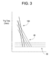
- FIG. 3 is a graph illustrating I ⁇ 4t ground fault trip functions plotted on a logarithmic scale for the trip unit of FIG. 1 ;
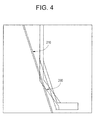
- FIG. 4 is a graph illustrating I ⁇ 4t ground fault trip functions compared with typical fuse trip functions plotted on a logarithmic scale.
- FIG. 5 is a graph illustrating I ⁇ 4t ground fault trip functions compared with typical circuit breaker trip functions plotted on a logarithmic scale.
- Ground fault (GF) monitoring system 2 includes a circuit interrupter trip unit 4 having a trip device 6 and a processor or CPU 8 having an associated memory 9.
- Trip unit 4 is operatively coupled to an electrical circuit 10 and a ground fault sensing unit 12.
- Ground fault sensing unit 12 monitors electrical circuit 10 for current leakages to ground. Upon sensing a current leakage, sensing unit 12 signals processor 6 to activate trip device 6 and interrupt current flow in electrical circuit 10.
- trip device 6 interrupts current to electrical circuit 10 based on a trip characteristic established by a ground fault trip function. The particular ground fault trip function employed is user selectable so as to match protection requirements for electrical circuit 10.
- trip unit 4 is coupled to a user interface adaptor or input/output device 14 that allows a user to select various operating parameters for trip device 6.
- the operating parameters establish desired response/trip times as well as provide coordination with downstream fuses and/or circuit breakers (not shown).
- Input/output device 14 also provides alarms to notify personnel of a problem with electrical circuit 10 in the event of a circuit interruption.
- trip unit 4 logs each sensed leakage and/or circuit interruption in an event log 16.
- ground fault protection is enabled for trip unit 4 as indicated in block 40. If ground fault protection is not enabled, the monitoring algorithm is not executed as indicated in block 42. If however, ground fault protection is enabled, a ground fault pick up level or threshold is established as indicate din block 44. Ground fault pickup is generally between 0.1 and 1 milliamps depending on breaker sensor parameters. After selecting the ground fault pick up threshold, a ground fault band is established as indicated in block 46.
- Trip unit 4 includes a plurality of ground fault trip function options. The particular option chosen depends or circuit component and/or breaker parameters for electrical circuit 10.
- processor 8 can be programmed with one of a plurality of constant ground fault trip functions indicated generally at 60, one of a plurality of inverse time functions, such as I ⁇ 2t functions 80 and in accordance with an exemplary embodiment of the invention, I ⁇ 4t (ampere-to-the-fourth-power-seconds) functions, two of which are indicated generally at 100.
- GF monitoring system 2 provides personnel with a greater level of flexibility in designing circuit protection schemes.
- the monitoring algorithm is executed and indicated in block 104 and GF monitoring system 2 is enabled to provide ground fault protection for electrical circuit 10.
- ground fault protection is executed every half cycle, e.g., every 10 ms for 50Hz and every 8.33 ms for 60 Hz.
- accumulator heating will occur per the selected ground fault trip function.
- K GF the trip function I ⁇ ⁇ 4 ⁇ t ; and f is the frequency.
- the present invention provides a ground fault circuit monitoring system having greater flexibility than previously possible with existing circuit protection schemes.
- the present invention provides a system that provides a level of circuit protection that match overload and short circuit protection speeds when desired. That is, as best shown in FIG. 4 and 5 , providing ground fault trip units with I ⁇ 4t inverse time functions such as indicated at 200, closer coordination is possible with downstream fuse trip functions, such as shown at 210 in FIG. 4 and circuit breaker trip functions such as shown at 220 in FIG. 5 .
Landscapes
- Emergency Protection Circuit Devices (AREA)
Applications Claiming Priority (1)
| Application Number | Priority Date | Filing Date | Title |
|---|---|---|---|
| US12/103,244 US20090257156A1 (en) | 2008-04-15 | 2008-04-15 | Method of setting a ground fault trip function for a trip unit and a trip unit having a defined trip function for ground fault protection |
Publications (1)
| Publication Number | Publication Date |
|---|---|
| EP2110917A2 true EP2110917A2 (de) | 2009-10-21 |
Family
ID=40886138
Family Applications (1)
| Application Number | Title | Priority Date | Filing Date |
|---|---|---|---|
| EP09157332A Withdrawn EP2110917A2 (de) | 2008-04-15 | 2009-04-03 | Verfahren zur Einstellung einer Erdfehler-Auslöseeinheit mit einer definierten Auslösefunktion zum Erdfehlerschutz |
Country Status (5)
| Country | Link |
|---|---|
| US (1) | US20090257156A1 (de) |
| EP (1) | EP2110917A2 (de) |
| JP (1) | JP2009261233A (de) |
| CN (1) | CN101562324A (de) |
| CA (1) | CA2662230A1 (de) |
Cited By (1)
| Publication number | Priority date | Publication date | Assignee | Title |
|---|---|---|---|---|
| CN112180205A (zh) * | 2020-08-28 | 2021-01-05 | 南京国电南自软件工程有限公司 | 一种配电网智能分布式单相接地选线方法及系统 |
Families Citing this family (5)
| Publication number | Priority date | Publication date | Assignee | Title |
|---|---|---|---|---|
| US9065270B2 (en) * | 2013-02-26 | 2015-06-23 | Caterpillar Inc. | Ground fault protection systems and methods |
| US9705310B2 (en) | 2013-11-26 | 2017-07-11 | Thomas & Betts International Llc | Adaptive fault clearing based on power transistor temperature |
| DE102014224173B4 (de) * | 2014-11-26 | 2023-08-10 | Siemens Aktiengesellschaft | Leistungsschalter |
| DE102016201651B4 (de) * | 2015-04-30 | 2020-01-30 | Siemens Aktiengesellschaft | Leistungsschalter |
| CN113725829B (zh) * | 2021-07-22 | 2022-06-28 | 西安交通大学 | 一种具有自动配合关系的配电网后备保护方法及系统 |
Family Cites Families (5)
| Publication number | Priority date | Publication date | Assignee | Title |
|---|---|---|---|---|
| US3968410A (en) * | 1974-09-10 | 1976-07-06 | General Electric Company | Static overcurrent relays |
| US5627716A (en) * | 1990-12-28 | 1997-05-06 | Eaton Corporation | Overcurrent protection device |
| US5875088A (en) * | 1998-02-17 | 1999-02-23 | Eaton Corporation | Electrical switching apparatus employing interlocks for first and second trip functions |
| US20050047045A1 (en) * | 2003-08-29 | 2005-03-03 | Puskar Michael P. | Circuit breaker and trip unit employing multiple function time selector switch |
| CN100539345C (zh) * | 2004-11-04 | 2009-09-09 | 河北工业大学 | 漏电突变动作无死区断路器及其运行方法 |
-
2008
- 2008-04-15 US US12/103,244 patent/US20090257156A1/en not_active Abandoned
-
2009
- 2009-04-03 EP EP09157332A patent/EP2110917A2/de not_active Withdrawn
- 2009-04-09 CA CA002662230A patent/CA2662230A1/en not_active Abandoned
- 2009-04-09 JP JP2009094674A patent/JP2009261233A/ja not_active Withdrawn
- 2009-04-15 CN CNA2009101331763A patent/CN101562324A/zh active Pending
Cited By (1)
| Publication number | Priority date | Publication date | Assignee | Title |
|---|---|---|---|---|
| CN112180205A (zh) * | 2020-08-28 | 2021-01-05 | 南京国电南自软件工程有限公司 | 一种配电网智能分布式单相接地选线方法及系统 |
Also Published As
| Publication number | Publication date |
|---|---|
| US20090257156A1 (en) | 2009-10-15 |
| CA2662230A1 (en) | 2009-10-15 |
| JP2009261233A (ja) | 2009-11-05 |
| CN101562324A (zh) | 2009-10-21 |
Similar Documents
| Publication | Publication Date | Title |
|---|---|---|
| EP2482409B1 (de) | Gleichstrom-Lichtbogendetektion und -schutz | |
| EP1804355B1 (de) | Detektion von und Schutz vor AC Lichtbogenfehlern | |
| EP2053716B1 (de) | Verfahren zur Detektion von Wechselstrom-Serienlichtbogenfehlern | |
| US8947843B2 (en) | Fast breaker failure detection for HVDC circuit breakers | |
| WO2014027571A1 (ja) | デジタル保護リレー、デジタル保護リレー試験装置、およびデジタル保護リレー試験方法 | |
| US20060200688A1 (en) | Power distribution system using solid state power controllers | |
| EP2728691B1 (de) | Schaltung zur Fehlerstromermittlung | |
| EP2110917A2 (de) | Verfahren zur Einstellung einer Erdfehler-Auslöseeinheit mit einer definierten Auslösefunktion zum Erdfehlerschutz | |
| US20090154033A1 (en) | Electrical Arc Fault Circuit Interrupter Apparatus and Method | |
| US7940051B2 (en) | Method for testing circuit breakers | |
| CN110967571B (zh) | 诊断电气保护设备跳闸原因的方法、辅助设备和电气系统 | |
| JP2016537631A (ja) | 回路の電気的故障を検出する方法 | |
| EP2659561B1 (de) | Verfahren und vorrichtung zur überwachung eines stromwandlers in einem differentialschutzsystem | |
| KR101265469B1 (ko) | 시간 특성을 고려한 경보 방법 및 시스템 | |
| CN110073562B (zh) | 过电流与短路探测器 | |
| CN101523681B (zh) | 用于提供保护控制的保护继电器和识别故障相的方法及设备 | |
| JP6509029B2 (ja) | 分電盤 | |
| EP2497175B1 (de) | Verfahren zur überwachung der abstufungsspanne zwischen zeit-strom-eigenschaften intelligenter elektronischer geräte | |
| EP1287599B1 (de) | Softwaregesteuerte auswertung eines fehlerstroms für schutz- und überwachungssysteme | |
| US11894668B2 (en) | System and method for discerning arcing in electrical wiring | |
| EP3944443A1 (de) | Einphasen-fehlerisolierung und wiederherstellung mit lastschätzung | |
| JP6840426B2 (ja) | 電源監視システム | |
| KR20090109494A (ko) | 접지 장애 트립 함수 설정 방법 | |
| US20110054713A1 (en) | Global trip unit | |
| EP4147061B1 (de) | Verfahren und vorrichtung zur detektion eines sicherungsausfalls |
Legal Events
| Date | Code | Title | Description |
|---|---|---|---|
| PUAI | Public reference made under article 153(3) epc to a published international application that has entered the european phase |
Free format text: ORIGINAL CODE: 0009012 |
|
| AK | Designated contracting states |
Kind code of ref document: A2 Designated state(s): AT BE BG CH CY CZ DE DK EE ES FI FR GB GR HR HU IE IS IT LI LT LU LV MC MK MT NL NO PL PT RO SE SI SK TR |
|
| STAA | Information on the status of an ep patent application or granted ep patent |
Free format text: STATUS: THE APPLICATION IS DEEMED TO BE WITHDRAWN |
|
| 18D | Application deemed to be withdrawn |
Effective date: 20121101 |