EP2110731A2 - Multi-directionnal input apparatus - Google Patents
Multi-directionnal input apparatus Download PDFInfo
- Publication number
- EP2110731A2 EP2110731A2 EP09005319A EP09005319A EP2110731A2 EP 2110731 A2 EP2110731 A2 EP 2110731A2 EP 09005319 A EP09005319 A EP 09005319A EP 09005319 A EP09005319 A EP 09005319A EP 2110731 A2 EP2110731 A2 EP 2110731A2
- Authority
- EP
- European Patent Office
- Prior art keywords
- drive shaft
- swinging member
- long hole
- input apparatus
- lever
- Prior art date
- Legal status (The legal status is an assumption and is not a legal conclusion. Google has not performed a legal analysis and makes no representation as to the accuracy of the status listed.)
- Granted
Links
Images



Classifications
-
- G—PHYSICS
- G05—CONTROLLING; REGULATING
- G05G—CONTROL DEVICES OR SYSTEMS INSOFAR AS CHARACTERISED BY MECHANICAL FEATURES ONLY
- G05G9/00—Manually-actuated control mechanisms provided with one single controlling member co-operating with two or more controlled members, e.g. selectively, simultaneously
- G05G9/02—Manually-actuated control mechanisms provided with one single controlling member co-operating with two or more controlled members, e.g. selectively, simultaneously the controlling member being movable in different independent ways, movement in each individual way actuating one controlled member only
- G05G9/04—Manually-actuated control mechanisms provided with one single controlling member co-operating with two or more controlled members, e.g. selectively, simultaneously the controlling member being movable in different independent ways, movement in each individual way actuating one controlled member only in which movement in two or more ways can occur simultaneously
- G05G9/047—Manually-actuated control mechanisms provided with one single controlling member co-operating with two or more controlled members, e.g. selectively, simultaneously the controlling member being movable in different independent ways, movement in each individual way actuating one controlled member only in which movement in two or more ways can occur simultaneously the controlling member being movable by hand about orthogonal axes, e.g. joysticks
-
- G—PHYSICS
- G05—CONTROLLING; REGULATING
- G05G—CONTROL DEVICES OR SYSTEMS INSOFAR AS CHARACTERISED BY MECHANICAL FEATURES ONLY
- G05G25/00—Other details or appurtenances of control mechanisms, e.g. supporting intermediate members elastically
- G05G25/02—Inhibiting the generation or transmission of noise
-
- G—PHYSICS
- G05—CONTROLLING; REGULATING
- G05G—CONTROL DEVICES OR SYSTEMS INSOFAR AS CHARACTERISED BY MECHANICAL FEATURES ONLY
- G05G9/00—Manually-actuated control mechanisms provided with one single controlling member co-operating with two or more controlled members, e.g. selectively, simultaneously
- G05G9/02—Manually-actuated control mechanisms provided with one single controlling member co-operating with two or more controlled members, e.g. selectively, simultaneously the controlling member being movable in different independent ways, movement in each individual way actuating one controlled member only
- G05G9/04—Manually-actuated control mechanisms provided with one single controlling member co-operating with two or more controlled members, e.g. selectively, simultaneously the controlling member being movable in different independent ways, movement in each individual way actuating one controlled member only in which movement in two or more ways can occur simultaneously
- G05G9/047—Manually-actuated control mechanisms provided with one single controlling member co-operating with two or more controlled members, e.g. selectively, simultaneously the controlling member being movable in different independent ways, movement in each individual way actuating one controlled member only in which movement in two or more ways can occur simultaneously the controlling member being movable by hand about orthogonal axes, e.g. joysticks
- G05G2009/04703—Mounting of controlling member
- G05G2009/04714—Mounting of controlling member with orthogonal axes
-
- Y—GENERAL TAGGING OF NEW TECHNOLOGICAL DEVELOPMENTS; GENERAL TAGGING OF CROSS-SECTIONAL TECHNOLOGIES SPANNING OVER SEVERAL SECTIONS OF THE IPC; TECHNICAL SUBJECTS COVERED BY FORMER USPC CROSS-REFERENCE ART COLLECTIONS [XRACs] AND DIGESTS
- Y10—TECHNICAL SUBJECTS COVERED BY FORMER USPC
- Y10T—TECHNICAL SUBJECTS COVERED BY FORMER US CLASSIFICATION
- Y10T74/00—Machine element or mechanism
- Y10T74/18—Mechanical movements
- Y10T74/18568—Reciprocating or oscillating to or from alternating rotary
-
- Y—GENERAL TAGGING OF NEW TECHNOLOGICAL DEVELOPMENTS; GENERAL TAGGING OF CROSS-SECTIONAL TECHNOLOGIES SPANNING OVER SEVERAL SECTIONS OF THE IPC; TECHNICAL SUBJECTS COVERED BY FORMER USPC CROSS-REFERENCE ART COLLECTIONS [XRACs] AND DIGESTS
- Y10—TECHNICAL SUBJECTS COVERED BY FORMER USPC
- Y10T—TECHNICAL SUBJECTS COVERED BY FORMER US CLASSIFICATION
- Y10T74/00—Machine element or mechanism
- Y10T74/20—Control lever and linkage systems
- Y10T74/20006—Resilient connections
-
- Y—GENERAL TAGGING OF NEW TECHNOLOGICAL DEVELOPMENTS; GENERAL TAGGING OF CROSS-SECTIONAL TECHNOLOGIES SPANNING OVER SEVERAL SECTIONS OF THE IPC; TECHNICAL SUBJECTS COVERED BY FORMER USPC CROSS-REFERENCE ART COLLECTIONS [XRACs] AND DIGESTS
- Y10—TECHNICAL SUBJECTS COVERED BY FORMER USPC
- Y10T—TECHNICAL SUBJECTS COVERED BY FORMER US CLASSIFICATION
- Y10T74/00—Machine element or mechanism
- Y10T74/20—Control lever and linkage systems
- Y10T74/20012—Multiple controlled elements
- Y10T74/20201—Control moves in two planes
Definitions
- the present invention relates to a multi-directional input apparatus which includes an operating member provided with a drive shaft and which outputs an electric signal in accordance with a tilting direction and a tilting angle of the drive shaft when the operating member is tilted. More particularly, the present invention relates to a multi-directional input apparatus including a swinging member which has a long hole through which the drive shaft is inserted and which is rotated when the drive shaft is tilted.
- the multi-directional input apparatus when the operating member supported such that the operating member is tiltable in multiple directions is tilted, an electric signal can be obtained which differs in accordance with the tilting direction and the tilting angle of the operating member. Therefore, the multi-directional input apparatus is suitable for use as, for example, an input apparatus in which functions of multiple control devices, such as an air conditioner, an audio device, and a navigation device, that are mounted on a vehicle are adjusted using a single operating member.
- multiple control devices such as an air conditioner, an audio device, and a navigation device
- Japanese Unexamined Patent Application Publication No. 6-12137 discloses an example of such a multi-directional input apparatus.
- This multi-directional input apparatus includes a swinging member that is rotatably supported on a base and an operating member provided with a drive shaft that is inserted through a long hole formed in the swinging member.
- the operating member is tilted in a direction that crosses an axial direction of the swinging member, the swinging member is rotated by the drive shaft and an electric signal corresponding to the rotation angle of the swinging member is output from a detector, such as a variable resistor.
- a pair of swinging members having the above-described structure may be arranged such that the axial directions thereof extend perpendicular to each other, and the drive shaft of the operating member may be inserted through long holes formed in the swinging members.
- the tilting direction and the tilting angle of the operating member tilted in an arbitrary direction can be detected from output values obtained by a pair of detectors which correspond to the swinging members.
- rolling elements such as bearings, are attached to the drive shaft of the operating member so that the rolling elements roll along the inner walls of the long holes in the swinging members when the operating member is tilted.
- the rolling elements are provided to prevent rattling when the operating member is repeatedly tilted and contact surfaces between the drive shaft of the operating member and the inner walls of the long holes are worn.
- Japanese Unexamined Patent Application Publication No. 2005-332156 discloses another example of a multi-directional input apparatus.
- This multi-directional input apparatus includes a swinging member and a swinging holder which is supported such that the swinging holder is rotatable along a plane perpendicular to an axial direction of the swinging member.
- a drive shaft of an operating member is rotatably supported by the swinging holder, and the axial direction of the drive shaft is substantially parallel to the axial direction of the swinging member.
- the tilting direction and the tilting angle of the operating member tilted in an arbitrary direction can be detected from output values obtained by a pair of detectors which correspond to the swinging member and the swinging holder.
- the rolling elements such as bearings, are attached to the drive shaft of the operating member to prevent wear. Therefore, even when the operating member is repeatedly tilted, a possibility that rattling will occur between the drive shaft of the operating member and the inner walls of the long holes in the swinging members is low.
- slight clearances must be provided between the rolling elements and the inner walls of the long holes so that the rolling elements attached to the drive shaft can be placed in the long holes. Therefore, in the case where, for example, the multi-directional input apparatus is mounted on a vehicle, there is a risk that the rolling elements will come into contact with the inner walls of the long holes due to vibration generated when the vehicle is driven.
- the present invention provides a multi-directional input apparatus in which an operating member inserted through a long hole is prevented from serving as a noise source in a vibrating environment without increasing the cost.
- a multi-directional input apparatus includes an operating member including a drive shaft; a base configured to support the operating member such that the operating member is tiltable in multiple directions; a long hole through which the drive shaft extends; and a swinging member supported on the base such that the swinging member is rotatable and such that an axial direction of the swinging member is substantially parallel to a longitudinal direction of the long hole.
- the swinging member is rotated by the drive shaft.
- At least one of the swinging member and the drive shaft is provided with an biasing unit configured to elastically bias the drive shaft against a side surface of an inner wall of the long hole.
- the drive shaft of the operating member inserted through the long hole in the swinging member is pressed against the inner wall of the through hole by an elastic biasing force applied by the biasing unit. Therefore, rattling between the drive shaft and the inner wall of the long hole can be prevented.
- rattling does not occur because the drive shaft is elastically biased by the biasing unit. Therefore, in the multi-directional input apparatus, the operating member does not serve as a source of noise, such as the rattling noise, in a vibrating environment.
- an inexpensive component such as a spring member and an elastic piece, can be used as the biasing unit. Therefore, even though the biasing unit is additionally used, the cost can be prevented from being increased.
- the biasing unit includes a spring member provided on one of the swinging member and the drive shaft.
- the elastic biasing force can be applied to the drive shaft simply by adding a single inexpensive spring member.
- the spring member is a leaf spring provided on the swinging member, the leaf spring having a bent portion extending substantially parallel to the axial direction and being in elastic contact with the drive shaft. In such a case, when the operating member is tilted and the drive shaft slides along the bent portion, a portion of the drive shaft which is in contact with the bent portion changes in accordance with the inclination angle of the operating member.
- the leaf spring includes an attachment portion which is externally fitted to a frame portion of the swinging member, the frame portion surrounding the long hole, and a tongue piece which extends from the attachment portion and includes the bent portion at an end of the tongue piece.
- the attachment portion is provided with a hole for completely exposing the long hole.
- Fig. 1 is a perspective view of a multi-directional input apparatus according to the embodiment of the present invention.
- Fig. 2 is a plan view of the multi-directional input apparatus.
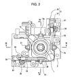
- Fig. 3 is a sectional view of Fig. 2 taken along line III-III.
- Fig. 4 is a sectional view of Fig. 2 taken along line IV-IV.
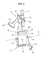
- Fig. 5 is an exploded perspective view of an operating lever and a drive lever included in the multi-directional input apparatus. In Fig. 2 , rotary motors are not shown.
- the multi-directional input apparatus shown in the above-mentioned figures is a main section of a force-sense-imparting input apparatus which is mounted on a vehicle and in which an electrically controlled force sensation is applied to an operating lever (operating member).
- the force-sense-imparting input apparatus is an input apparatus having a force-feedback function in which functions of control devices, such as an air conditioner, an audio device, and a navigation device, that are mounted on the vehicle are adjusted using a single operating member.
- An operation of selecting a device or adjusting the functions of the device are performed by manually operating the operating lever.
- a resistive sensation or an external force, such as thrust is applied in accordance with the amount by which the operating lever is operated and the direction in which the operating lever is operated.
- a good operational feel can be produced and a desired operation can be reliably performed.
- the multi-directional input apparatus is accommodated in a housing (not shown) having a through hole in a top surface thereof and is installed in, for example, a center console of a vehicle.
- An input operation can be performed by tilting an operating lever 1 which projects upward through the through hole.
- the multi-directional input apparatus includes a base (frame) 3 which stands upright on a circuit board 2; first and second drive levers 4 and 5 which are rotatably supported on the base 3 such that axial directions of the first and second drive levers 4 and 5 extend perpendicular to each other; first and second rotary motors 6 and 7 mounted on the circuit board 2 such that rotating shafts 6a and 7a of the first and second rotary motors 6 and 7, respectively, extend perpendicular to each other; rotary encoders 8 and 9 and photo-interrupters 10 and 11 mounted on the circuit board 2; and a controller (not shown).
- the operating lever 1 can be tilted in an arbitrary direction, and the drive levers 4 and 5 can be rotated by an operational force applied by the operating lever 1.
- the operating lever 1 includes a drive shaft 1a which extends downward, and the drive shaft 1a is inserted through a long hole 4a formed in the first drive lever 4.
- a lever shaft 12, which functions as a rotating shaft, extends through a central wide portion 1b (see Fig. 3 ) of the operating lever 1.
- the operating lever 1 is rotatably supported on the second drive lever 5 by the lever shaft 12.
- a sliding member 13 is fitted between the central wide portion 1b of the operating lever 1 and a restraining member 36.
- the sliding member 13 is in contact with a spherical inner wall surface (receiving surface) of the restraining member 36, which is formed integrally with the base 3.
- An operating knob (not shown) is attached to the operating lever 1 at the top end thereof.
- the base 3 includes two support plates 31 and 32 which are combined together with connecting plates 33 and spacers 34 provided therebetween.
- the support plate 31 is a metal plate having an L shape in a plan view
- the support plate 32 is a metal plate having a W shape in a plan view.
- the support plates 31 and 32 are disposed so as to face each other and are strongly fixed to each other by crimping such that the connecting plates 33 are provided between the support plates 31 and 32 at the ends thereof.
- the distance between the support plates 31 and 32 is accurately set by the spacers 34 fixed to the support plates 31 and 32 with screws 35.
- the first drive lever 4 includes a pair of shafts 41 which face each other, a frame portion 42 having the long hole 4a formed therein, and a gear portion 43 (see Fig. 5 ).
- the gear portion 43 projects from a side wall which stands upright at an end of the frame portion 42 and includes a tooth section 4b at an end of the gear portion 43.
- An L-shaped detection plate 44 is fixed to a side wall which stands upright at the other end of the frame portion 42.
- the shafts 41 are rotatably attached to a top-end portion of the base 3 with bearings 45.
- a rotational centerline C (axial line of the first drive lever 4) which extends through the shafts 41 is parallel to the axial line of the lever shaft 12 and the longitudinal direction of the long hole 4a.
- the first drive lever 4 has a leaf spring 15 attached thereto (see Figs. 3 and 5 ).
- the leaf spring 15 causes the drive shaft 1a of the operating lever 1 to be in elastic contact with the inner wall of the long hole 4a.
- the leaf spring 15 includes an attachment portion 16 and a tongue piece 17.
- the attachment portion 16 has a hole 16a and is externally attached to the frame portion 42.
- the tongue piece 17 extends from the attachment portion 16 and has a bent portion 17a at an end thereof.
- the hole 16a is a long hole that is slightly larger than the long hole 4a, and the long hole 4a is completely exposed at the hole 16a when the leaf spring 15 is attached to the frame portion 42.
- the bent portion 17a of the tongue piece 17 linearly extends in the axial direction (longitudinal direction of the long hole 4a) of the first drive lever 4, and is formed such that the bent portion 17a comes into elastic contact with a bottom end portion of the drive shaft 1a.
- the drive shaft 1a is elastically biased against a side surface of the inner wall of the long hole 4a.
- the second drive lever 5 includes a pair of shafts 51 which face each other, a holder 52 on which the operating lever 1 is supported by the lever shaft 12, and a gear portion 53 (see Fig. 5 ).
- the gear portion 53 projects from the holder 52 at one side thereof and includes a tooth section 5a at the end of the gear portion 53.
- An L-shaped detection plate 54 is fixed to the holder 52 at the other side.
- the shafts 51 are rotatably attached to the top-end portion of the base 3 with bearings 55.
- a rotational centerline (axial line of the second drive lever 5) which extends through the shafts 51 is perpendicular to the axial line of the first drive lever 4 and the axial line of the lever shaft 12.
- the first and second drive levers 4 and 5 are supported on the base 3 such that the axial lines thereof extend perpendicular to each other, and the operating lever 1 extends through a section where the drive levers 4 and 5 intersect. Accordingly, the operating lever 1 is supported on the base 3 such that the operating lever 1 can be tilted in multiple directions.
- the detection plate 54 passes through a recess 11a in the photo-interrupter 11.
- the second drive lever 5 supports the operating lever 1 and serves as a swinging holder which rotates when the operating lever 1 is tilted.
- the rotary encoder 8 includes the above-described code plate 81 and a photo-interrupter 82 which is mounted on the circuit board 2. A part of the code plate 81 is placed in a recess 82a in the photo-interrupter 82.
- the photo-interrupter 82 includes an LED (light emitting element) and a phototransistor (light receiving element) which face each other across the recess 82a, and information regarding the rotation of the code plate 81 can be obtained by the photo-interrupter 82.
- the rotary encoder 9 includes the above-described code plate 91 and a photo-interrupter 92 which is mounted on the circuit board 2. A part of the code plate 91 is placed in a recess 92a in the photo-interrupter 92, and information regarding the rotation of the code plate 91 can be obtained by the photo-interrupter 92.
- the signals output from the photo-interrupters 10 and 11 are fed to the controller (not shown), and the controller calculates reference positions of the drive levers 4 and 5.
- the controller also receives signals obtained by the photo-interrupters 82 and 92 in the rotary encoders 8 and 9, respectively, and calculates the directions and amounts of rotation of the drive levers 4 and 5 with respect to the reference positions.
- the controller reads the detection signals obtained by the photo-interrupters 10 and 11 and outputs the control signals to the rotary motors 6 and 7. Accordingly, the rotary motors 6 and 7 rotate the drive levers 4 and 5, respectively, so that the operating lever 1 returns to a neutral position. In this step, the rotary motors 6 and 7 rotate the drive levers 4 and 5 such that the outputs from the photo-interrupters 10 and 11 change from OFF to ON. The operating lever 1 reaches the neutral position when the outputs from the photo-interrupters 10 and 11 are both changed from OFF to ON.
- the drive shaft 1a is softly pressed against a side surface of the inner wall of the long hole 4a. Therefore, rattling between the drive shaft 1a and the inner wall of the long hole 4a can be prevented. Even if the tilting operation is repeated and the contact surfaces between the drive shaft 1a and the inner wall of the long hole 4a are worn, the drive shaft 1a is prevented from rattling since the drive shaft 1a is elastically biased by the tongue piece 17 of the leaf spring 15. Therefore, in the multi-directional input apparatus, the operating lever 1 does not serve as a source of noise, such as the rattling noise, in a vibrating environment.
Landscapes
- Physics & Mathematics (AREA)
- General Physics & Mathematics (AREA)
- Engineering & Computer Science (AREA)
- Automation & Control Theory (AREA)
- Switches With Compound Operations (AREA)
- Mechanical Control Devices (AREA)
Abstract
Description
- The present invention relates to a multi-directional input apparatus which includes an operating member provided with a drive shaft and which outputs an electric signal in accordance with a tilting direction and a tilting angle of the drive shaft when the operating member is tilted. More particularly, the present invention relates to a multi-directional input apparatus including a swinging member which has a long hole through which the drive shaft is inserted and which is rotated when the drive shaft is tilted.
- In this type of multi-directional input apparatus, when the operating member supported such that the operating member is tiltable in multiple directions is tilted, an electric signal can be obtained which differs in accordance with the tilting direction and the tilting angle of the operating member. Therefore, the multi-directional input apparatus is suitable for use as, for example, an input apparatus in which functions of multiple control devices, such as an air conditioner, an audio device, and a navigation device, that are mounted on a vehicle are adjusted using a single operating member.
- Japanese Unexamined Patent Application Publication No.
6-12137 6-12137 - Japanese Unexamined Patent Application Publication No.
2005-332156 - In the structure of the related art disclosed in Japanese Unexamined Patent Application Publication No.
6-12137 - In the structure of the related art disclosed in Japanese Unexamined Patent Application Publication No.
2005-332156 - In light of the above-described situation, the present invention provides a multi-directional input apparatus in which an operating member inserted through a long hole is prevented from serving as a noise source in a vibrating environment without increasing the cost.
- According to an aspect of the present invention, a multi-directional input apparatus includes an operating member including a drive shaft; a base configured to support the operating member such that the operating member is tiltable in multiple directions; a long hole through which the drive shaft extends; and a swinging member supported on the base such that the swinging member is rotatable and such that an axial direction of the swinging member is substantially parallel to a longitudinal direction of the long hole. When the operating member is tilted in a direction crossing the axial direction of the swinging member, the swinging member is rotated by the drive shaft. At least one of the swinging member and the drive shaft is provided with an biasing unit configured to elastically bias the drive shaft against a side surface of an inner wall of the long hole.
- In the multi-directional input apparatus having the above-described structure, the drive shaft of the operating member inserted through the long hole in the swinging member is pressed against the inner wall of the through hole by an elastic biasing force applied by the biasing unit. Therefore, rattling between the drive shaft and the inner wall of the long hole can be prevented. In addition, even when the tilting operation is repeated and the contact surfaces between the drive shaft of the operating member and the inner wall of the long hole are worn, rattling does not occur because the drive shaft is elastically biased by the biasing unit. Therefore, in the multi-directional input apparatus, the operating member does not serve as a source of noise, such as the rattling noise, in a vibrating environment. In addition, an inexpensive component, such as a spring member and an elastic piece, can be used as the biasing unit. Therefore, even though the biasing unit is additionally used, the cost can be prevented from being increased.
- In the above-described structure, preferably, the biasing unit includes a spring member provided on one of the swinging member and the drive shaft. In such a case, the elastic biasing force can be applied to the drive shaft simply by adding a single inexpensive spring member. In this case, preferably, the spring member is a leaf spring provided on the swinging member, the leaf spring having a bent portion extending substantially parallel to the axial direction and being in elastic contact with the drive shaft. In such a case, when the operating member is tilted and the drive shaft slides along the bent portion, a portion of the drive shaft which is in contact with the bent portion changes in accordance with the inclination angle of the operating member. Therefore, even when the tilting operation is repeated, the portion of the drive shaft which is in contact with the leaf spring does not easily wear. As a result, detection errors caused by wear can be easily prevented. In addition, preferably, the leaf spring includes an attachment portion which is externally fitted to a frame portion of the swinging member, the frame portion surrounding the long hole, and a tongue piece which extends from the attachment portion and includes the bent portion at an end of the tongue piece. The attachment portion is provided with a hole for completely exposing the long hole. In this case, the leaf spring can be easily attached to the swinging member and the risk that the attachment portion of the leaf spring surrounding the long hole will interfere with the drive shaft can be eliminated.
-
-
Fig. 1 is a perspective view of a multi-directional input apparatus according to an embodiment of the present invention; -
Fig. 2 is a plan view of the multi-directional input apparatus; -
Fig. 3 is a sectional view ofFig. 2 taken along line III-III; -
Fig. 4 is a sectional view ofFig. 2 taken along line IV-IV; and -
Fig. 5 is an exploded perspective view of an operating lever and a drive lever included in the multi-directional input apparatus. - An embodiment of the present invention will be described with reference to the accompanying drawings.
Fig. 1 is a perspective view of a multi-directional input apparatus according to the embodiment of the present invention.Fig. 2 is a plan view of the multi-directional input apparatus.Fig. 3 is a sectional view ofFig. 2 taken along line III-III.Fig. 4 is a sectional view ofFig. 2 taken along line IV-IV.Fig. 5 is an exploded perspective view of an operating lever and a drive lever included in the multi-directional input apparatus. InFig. 2 , rotary motors are not shown. - The multi-directional input apparatus shown in the above-mentioned figures is a main section of a force-sense-imparting input apparatus which is mounted on a vehicle and in which an electrically controlled force sensation is applied to an operating lever (operating member). The force-sense-imparting input apparatus is an input apparatus having a force-feedback function in which functions of control devices, such as an air conditioner, an audio device, and a navigation device, that are mounted on the vehicle are adjusted using a single operating member. An operation of selecting a device or adjusting the functions of the device are performed by manually operating the operating lever. At this time, a resistive sensation or an external force, such as thrust, is applied in accordance with the amount by which the operating lever is operated and the direction in which the operating lever is operated. Thus, a good operational feel can be produced and a desired operation can be reliably performed.
- The multi-directional input apparatus according to the present embodiment is accommodated in a housing (not shown) having a through hole in a top surface thereof and is installed in, for example, a center console of a vehicle. An input operation can be performed by tilting an operating
lever 1 which projects upward through the through hole. The multi-directional input apparatus includes a base (frame) 3 which stands upright on acircuit board 2; first and second drive levers 4 and 5 which are rotatably supported on thebase 3 such that axial directions of the first and second drive levers 4 and 5 extend perpendicular to each other; first and secondrotary motors 6 and 7 mounted on thecircuit board 2 such thatrotating shafts rotary motors 6 and 7, respectively, extend perpendicular to each other;rotary encoders interrupters circuit board 2; and a controller (not shown). The operatinglever 1 can be tilted in an arbitrary direction, and the drive levers 4 and 5 can be rotated by an operational force applied by the operatinglever 1. - The operating
lever 1 includes adrive shaft 1a which extends downward, and thedrive shaft 1a is inserted through along hole 4a formed in thefirst drive lever 4. Alever shaft 12, which functions as a rotating shaft, extends through a centralwide portion 1b (seeFig. 3 ) of the operatinglever 1. The operatinglever 1 is rotatably supported on thesecond drive lever 5 by thelever shaft 12. A slidingmember 13 is fitted between the centralwide portion 1b of the operatinglever 1 and a restrainingmember 36. The slidingmember 13 is in contact with a spherical inner wall surface (receiving surface) of the restrainingmember 36, which is formed integrally with thebase 3. When the operatinglever 1 is tilted, the slidingmember 13 slides along the inner wall surface of the restrainingmember 36. An operating knob (not shown) is attached to the operatinglever 1 at the top end thereof. - The
base 3 includes twosupport plates plates 33 andspacers 34 provided therebetween. Thesupport plate 31 is a metal plate having an L shape in a plan view, and thesupport plate 32 is a metal plate having a W shape in a plan view. Thesupport plates plates 33 are provided between thesupport plates support plates spacers 34 fixed to thesupport plates screws 35. - The
first drive lever 4 includes a pair ofshafts 41 which face each other, aframe portion 42 having thelong hole 4a formed therein, and a gear portion 43 (seeFig. 5 ). Thegear portion 43 projects from a side wall which stands upright at an end of theframe portion 42 and includes atooth section 4b at an end of thegear portion 43. An L-shapeddetection plate 44 is fixed to a side wall which stands upright at the other end of theframe portion 42. Theshafts 41 are rotatably attached to a top-end portion of thebase 3 withbearings 45. A rotational centerline C (axial line of the first drive lever 4) which extends through theshafts 41 is parallel to the axial line of thelever shaft 12 and the longitudinal direction of thelong hole 4a. When thefirst drive lever 4 is rotated, thedetection plate 44 passes through arecess 10a in the photo-interrupter 10. Thefirst drive lever 4 serves as a swinging member which rotates when the operatinglever 1 is tilted. - In addition, the
first drive lever 4 has aleaf spring 15 attached thereto (seeFigs. 3 and5 ). Theleaf spring 15 causes thedrive shaft 1a of the operatinglever 1 to be in elastic contact with the inner wall of thelong hole 4a. Theleaf spring 15 includes anattachment portion 16 and atongue piece 17. Theattachment portion 16 has ahole 16a and is externally attached to theframe portion 42. Thetongue piece 17 extends from theattachment portion 16 and has abent portion 17a at an end thereof. Thehole 16a is a long hole that is slightly larger than thelong hole 4a, and thelong hole 4a is completely exposed at thehole 16a when theleaf spring 15 is attached to theframe portion 42. Thebent portion 17a of thetongue piece 17 linearly extends in the axial direction (longitudinal direction of thelong hole 4a) of thefirst drive lever 4, and is formed such that thebent portion 17a comes into elastic contact with a bottom end portion of thedrive shaft 1a. Thus, thedrive shaft 1a is elastically biased against a side surface of the inner wall of thelong hole 4a. - The
second drive lever 5 includes a pair ofshafts 51 which face each other, aholder 52 on which theoperating lever 1 is supported by thelever shaft 12, and a gear portion 53 (seeFig. 5 ). Thegear portion 53 projects from theholder 52 at one side thereof and includes atooth section 5a at the end of thegear portion 53. An L-shapeddetection plate 54 is fixed to theholder 52 at the other side. Theshafts 51 are rotatably attached to the top-end portion of thebase 3 withbearings 55. A rotational centerline (axial line of the second drive lever 5) which extends through theshafts 51 is perpendicular to the axial line of thefirst drive lever 4 and the axial line of thelever shaft 12. Thus, the first and second drive levers 4 and 5 are supported on thebase 3 such that the axial lines thereof extend perpendicular to each other, and the operatinglever 1 extends through a section where the drive levers 4 and 5 intersect. Accordingly, the operatinglever 1 is supported on thebase 3 such that the operatinglever 1 can be tilted in multiple directions. When thesecond drive lever 5 is rotated, thedetection plate 54 passes through arecess 11a in the photo-interrupter 11. Thesecond drive lever 5 supports the operatinglever 1 and serves as a swinging holder which rotates when the operatinglever 1 is tilted. - The
rotary motors 6 and 7 are mounted on thecircuit board 2 such that therotating shafts rotating shaft 6a of the firstrotary motor 6 is connected to a central section of acode plate 81 included in therotary encoder 8, and rotates together with thecode plate 81. When an operating force for rotating thefirst drive lever 4 is applied, therotating shaft 6a is rotated by thegear portion 43. Similarly, therotating shaft 7a of the second rotary motor 7 is connected to a central section of acode plate 91 included in therotary encoder 9, and rotates together with thecode plate 91. When an operating force for rotating thesecond drive lever 5 is applied, therotating shaft 7a is rotated by thegear portion 53. - The
rotary encoder 8 includes the above-describedcode plate 81 and a photo-interrupter 82 which is mounted on thecircuit board 2. A part of thecode plate 81 is placed in arecess 82a in the photo-interrupter 82. The photo-interrupter 82 includes an LED (light emitting element) and a phototransistor (light receiving element) which face each other across therecess 82a, and information regarding the rotation of thecode plate 81 can be obtained by the photo-interrupter 82. Similarly, therotary encoder 9 includes the above-describedcode plate 91 and a photo-interrupter 92 which is mounted on thecircuit board 2. A part of thecode plate 91 is placed in arecess 92a in the photo-interrupter 92, and information regarding the rotation of thecode plate 91 can be obtained by the photo-interrupter 92. - The photo-
interrupter 10 includes an LED and a phototransistor (not shown) which face each other across therecess 10a. The photo-interrupter 10 outputs an ON signal when thedetection plate 44 of thefirst drive lever 4 is not placed in therecess 10a. When thefirst drive lever 4 is rotated and thedetection plate 44 enters therecess 10a, the light emitted from the LED is blocked and an OFF signal is output from the photo-interrupter 10. Similarly, the photo-interrupter 11 outputs an ON signal when thedetection plate 54 of thesecond drive lever 5 is not placed in therecess 11a. When thedetection plate 54 enters therecess 11a, an OFF signal is output from the photo-interrupter 11. The signals output from the photo-interrupters interrupters rotary encoders - The above-described controller outputs control signals determined on the basis of data and programs stored in a memory to the
rotary motors 6 and 7. The control signals correspond to an operational feel to be produced by the operatinglever 1, and represents commands for, for example, generating vibrations or changing an operational force (resistive force or thrust). Circuit components of the controller are mounted on the bottom surface of thecircuit board 2 or on another circuit board that is not shown in the figure. - The operation of the multi-directional input apparatus having the above structure will be now be described. When the system of the multi-directional input apparatus is activated (turned on), the controller reads the detection signals obtained by the photo-
interrupters rotary motors 6 and 7. Accordingly, therotary motors 6 and 7 rotate the drive levers 4 and 5, respectively, so that the operatinglever 1 returns to a neutral position. In this step, therotary motors 6 and 7 rotate the drive levers 4 and 5 such that the outputs from the photo-interrupters lever 1 reaches the neutral position when the outputs from the photo-interrupters - Thus, the operating
lever 1 is automatically returned to the neutral position. In this state, when an operator tilts the operatinglever 1 in a certain direction, thefirst drive lever 4 and thesecond drive lever 5 are rotated by thedrive shaft 1a of the operatinglever 1 in accordance with the direction in which theoperating lever 1 is tilted. Thecode plate 81 is rotated when thefirst drive lever 4 rotates around the center of theshafts 41, and thecode plate 91 is rotated when thesecond drive lever 5 rotates around the center of theshafts 51. Accordingly, the information regarding the rotations of thecode plates interrupters rotary encoders - The controller calculates the directions and amounts of rotations of the drive levers 4 and 5 on the basis of the detection signals from the photo-
interrupters interrupters rotary motors 6 and 7. For example, when the operatinglever 1 is tilted in a certain direction by a certain amount, rotating forces based on the above-described control signals are transmitted from therotary motors 6 and 7 to the drive levers 4 and 5, respectively. Accordingly, a resistive force is applied to the operatinglever 1 through the drive levers 4 and 5 against the force applied to tilt the operatinglever 1. As a result, the operator who manually operates the operatinglever 1 recognizes the force applied to the operatinglever 1 as a click feel. - Thus, in the multi-directional input apparatus according to the present embodiment, the
first drive lever 4 has thelong hole 4a through which thedrive shaft 1a of the operatinglever 1 is inserted, and thefirst drive lever 4 is rotated by thedrive shaft 1a when the operatinglever 1 is tilted in a direction which crosses the axial direction of thefirst drive lever 4. Since theleaf spring 15 is attached to thefirst drive lever 4, thedrive shaft 1a is prevented from rattling in thelong hole 4a. More specifically, in the multi-directional input apparatus, the tongue piece 17 (bent portion 17a) of theleaf spring 15 is in elastic contact with the bottom end portion of thedrive shaft 1a, as shown inFig. 3 , so that thedrive shaft 1a is softly pressed against a side surface of the inner wall of thelong hole 4a. Therefore, rattling between thedrive shaft 1a and the inner wall of thelong hole 4a can be prevented. Even if the tilting operation is repeated and the contact surfaces between thedrive shaft 1a and the inner wall of thelong hole 4a are worn, thedrive shaft 1a is prevented from rattling since thedrive shaft 1a is elastically biased by thetongue piece 17 of theleaf spring 15. Therefore, in the multi-directional input apparatus, the operatinglever 1 does not serve as a source of noise, such as the rattling noise, in a vibrating environment. In addition, the noise can be prevented simply by adding asingle leaf spring 15, which is inexpensive, and theleaf spring 15 can be easily attached to thefirst drive lever 4 simply by externally fitting theattachment portion 16 to theframe portion 42 which surrounds thelong hole 4a. Therefore, the cost of the apparatus can be prevented from being increased. - In addition, according to the present embodiment, the
leaf spring 15 includes thebent portion 17a which extends substantially parallel to the axial direction of thefirst drive lever 4, and thebent portion 17a is in elastic contact with thedrive shaft 1a. Therefore, when the operatinglever 1 is tilted and thedrive shaft 1a slides along thebent portion 17a, a portion of thedrive shaft 1a which is in contact with thebent portion 17a changes in accordance with the inclination angle of the operatinglever 1. Therefore, even when the tilting operation is repeated, the portion of thedrive shaft 1a which is in contact with theleaf spring 15 does not easily wear. As a result, detection errors caused by wear can be easily prevented. In addition, theattachment portion 16 of theleaf spring 15 has thehole 16a at which thelong hole 4a is completely exposed. Therefore, theattachment portion 16, which is disposed so as to surround thelong hole 4a, is prevented from interfering with thedrive shaft 1a. - According to the above-described embodiment, the
leaf spring 15 which elastically biases thedrive shaft 1a of the operatinglever 1 is attached to thefirst drive lever 4 which has thelong hole 4a. However, a spring member or an elastic piece other than the leaf spring may also be attached to thefirst drive lever 4. In addition, an biasing unit including a spring member or an elastic piece may also be provided on thedrive shaft 1a such that the biasing unit is in elastic contact with a suitable portion (for example, the frame portion 42) of thefirst drive lever 4. Also in this case, effects similar to the above-described effects can be obtained. The present invention may also be applied to reduce noise in multi-directional input apparatuses other than the force-sense-imparting input apparatus.
Claims (4)
- A multi-directional input apparatus comprising:an operating member (1) including a drive shaft (1a);a base (3) configured to support the operating member (1) such that the operating member (1) is tiltable in multiple directions;a swinging member (4) having a long hole (4a) through which the drive shaft (1a) extends and being supported on the base (3) such that the swinging member (4) is rotatable and such that an axial direction of the swinging member (4) is substantially parallel to a longitudinal direction of the long hole (4a),wherein, when the operating member (1) is tilted in a direction crossing the axial direction of the swinging member (4), the swinging member (4) is rotated by the drive shaft (1a), andcharacterized in that at least one of the swinging member (4) and the drive shaft (1a) is provided with biasing means configured to elastically bias the drive shaft (1a) against a side surface of an inner wall of the long hole (4a).
- The multi-directional input apparatus according to claim 1,
characterized in that the biasing means includes a spring member provided on one of the swinging member (4) and the drive shaft (1a). - The multi-directional input apparatus according to claim 2,
characterized in that the spring member is a leaf spring (15) provided on the swinging member (4), the leaf spring (15) having a bent portion (17a) extending substantially parallel to the axial direction and being in elastic contact with the drive shaft (1a). - The multi-directional input apparatus according to claim 3,
characterized in that the leaf spring (15) includes an attachment portion (16) and a tongue piece (17), the attachment portion (16) being externally fitted to a frame portion of the swinging member (4), the frame portion surrounding the long hole (4a), the tongue piece (17) extending from the attachment portion (16) and including the bent portion (17a) toward an end of the tongue piece (17), and the attachment portion (16) is provided with a hole (16a) for completely exposing the long hole (4a).
Applications Claiming Priority (1)
| Application Number | Priority Date | Filing Date | Title |
|---|---|---|---|
| JP2008105879A JP5155725B2 (en) | 2008-04-15 | 2008-04-15 | Multi-directional input device |
Publications (3)
| Publication Number | Publication Date |
|---|---|
| EP2110731A2 true EP2110731A2 (en) | 2009-10-21 |
| EP2110731A3 EP2110731A3 (en) | 2010-04-28 |
| EP2110731B1 EP2110731B1 (en) | 2012-06-06 |
Family
ID=40673142
Family Applications (1)
| Application Number | Title | Priority Date | Filing Date |
|---|---|---|---|
| EP09005319A Active EP2110731B1 (en) | 2008-04-15 | 2009-04-14 | Multi-directionnal input apparatus |
Country Status (4)
| Country | Link |
|---|---|
| US (1) | US8230755B2 (en) |
| EP (1) | EP2110731B1 (en) |
| JP (1) | JP5155725B2 (en) |
| CN (1) | CN101561690B (en) |
Families Citing this family (4)
| Publication number | Priority date | Publication date | Assignee | Title |
|---|---|---|---|---|
| WO2013070938A1 (en) | 2011-11-08 | 2013-05-16 | Ross-Hime Designs, Incorporated | Robotic manipulator with spherical joints |
| US9823686B1 (en) * | 2016-08-15 | 2017-11-21 | Clause Technology | Three-axis motion joystick |
| US9889874B1 (en) * | 2016-08-15 | 2018-02-13 | Clause Technology | Three-axis motion joystick |
| AT520763B1 (en) * | 2017-12-21 | 2022-09-15 | Hans Kuenz Gmbh | crane control |
Citations (2)
| Publication number | Priority date | Publication date | Assignee | Title |
|---|---|---|---|---|
| JPH0612137A (en) | 1992-05-25 | 1994-01-21 | Sakae Tsushin Kogyo Kk | Operation shaft guide structure |
| JP2005332156A (en) | 2004-05-19 | 2005-12-02 | Alps Electric Co Ltd | Force sense giving type input device |
Family Cites Families (23)
| Publication number | Priority date | Publication date | Assignee | Title |
|---|---|---|---|---|
| US3554459A (en) * | 1968-01-20 | 1971-01-12 | Daiwa Seiko Co | Fishing rod reel |
| US3638952A (en) * | 1969-04-17 | 1972-02-01 | Itsuki Ban | Tape drive speed changing apparatus |
| CA949663A (en) * | 1971-12-24 | 1974-06-18 | Matsushita Electric Industrial Co., Ltd. | Device for simultaneously controlling a plurality of variable resistors |
| US3757597A (en) * | 1972-10-20 | 1973-09-11 | France Etat | Aiming device |
| US4248102A (en) * | 1977-11-17 | 1981-02-03 | Mitsumi Electric Co. Ltd. | Push button type tuner apparatus |
| JPS5643848Y2 (en) * | 1979-05-17 | 1981-10-14 | ||
| JPS58176719A (en) * | 1982-04-08 | 1983-10-17 | Nippon Plast Co Ltd | Control lever device |
| JPS5949225U (en) * | 1982-09-22 | 1984-04-02 | 富士重工業株式会社 | Anti-vibration structure for automatic transmission select lever knob |
| US4587510A (en) * | 1983-10-19 | 1986-05-06 | Wico Corporation | Analog joystick controller |
| US4607159A (en) * | 1983-12-27 | 1986-08-19 | North American Philips Consumer Electronics Corp. | Optical joystick controller with intersecting spring means |
| GB2183795B (en) * | 1985-12-03 | 1989-10-04 | Kubota Ltd | Valve control structure for working vehicle |
| US4857881A (en) * | 1988-07-08 | 1989-08-15 | Hayes Technology | Joystick with spring disconnect |
| JP2605694Y2 (en) * | 1992-05-29 | 2000-07-31 | 株式会社ケンウッド | Leaf spring holding structure |
| JPH0863250A (en) * | 1994-08-17 | 1996-03-08 | Riken Kaki Kogyo Kk | Interlocking mechanism |
| TW353171B (en) * | 1995-05-10 | 1999-02-21 | Nintendo Co Ltd | Manipulator provided with an analog joy stick |
| US6259433B1 (en) * | 1996-05-14 | 2001-07-10 | Norman H. Meyers | Digital optical joystick with mechanically magnified resolution |
| JP3402988B2 (en) * | 1997-01-31 | 2003-05-06 | 三洋電機株式会社 | Up and down cam mechanism of electronic component mounting device |
| DE19861141B4 (en) * | 1998-08-21 | 2006-11-02 | ITT Manufacturing Enterprises, Inc., Wilmington | joystick |
| JP4377047B2 (en) * | 2000-01-11 | 2009-12-02 | 株式会社小松製作所 | Operation lever device |
| FR2805576B1 (en) * | 2000-02-25 | 2002-10-31 | Renault | DEVICE FOR CONNECTING TWO ELEMENTS VIA A AXIS |
| JP3934394B2 (en) * | 2001-10-30 | 2007-06-20 | アルプス電気株式会社 | Haptic input device |
| US7059207B2 (en) * | 2003-09-30 | 2006-06-13 | Joel Steven Harris | Motor driven sampling apparatus for material collection |
| GB0526062D0 (en) * | 2005-12-22 | 2006-02-01 | Penny & Giles Controls Ltd | Joystick controller |
-
2008
- 2008-04-15 JP JP2008105879A patent/JP5155725B2/en active Active
-
2009
- 2009-04-14 EP EP09005319A patent/EP2110731B1/en active Active
- 2009-04-15 US US12/424,256 patent/US8230755B2/en active Active
- 2009-04-15 CN CN2009101331918A patent/CN101561690B/en active Active
Patent Citations (2)
| Publication number | Priority date | Publication date | Assignee | Title |
|---|---|---|---|---|
| JPH0612137A (en) | 1992-05-25 | 1994-01-21 | Sakae Tsushin Kogyo Kk | Operation shaft guide structure |
| JP2005332156A (en) | 2004-05-19 | 2005-12-02 | Alps Electric Co Ltd | Force sense giving type input device |
Also Published As
| Publication number | Publication date |
|---|---|
| EP2110731A3 (en) | 2010-04-28 |
| JP2009258904A (en) | 2009-11-05 |
| JP5155725B2 (en) | 2013-03-06 |
| US8230755B2 (en) | 2012-07-31 |
| CN101561690A (en) | 2009-10-21 |
| EP2110731B1 (en) | 2012-06-06 |
| US20090255353A1 (en) | 2009-10-15 |
| CN101561690B (en) | 2011-08-10 |
Similar Documents
| Publication | Publication Date | Title |
|---|---|---|
| US8400333B2 (en) | Multi-directional input apparatus | |
| EP2110731B1 (en) | Multi-directionnal input apparatus | |
| US20050099387A1 (en) | Force-feedback input device | |
| US20110048153A1 (en) | Joystick | |
| US4581609A (en) | X-Y position input device for display system | |
| US6504115B2 (en) | Multidirectional input device | |
| CN101571729A (en) | Multi-directional input apparatus | |
| JP4596020B2 (en) | Vehicle control device | |
| US6366442B1 (en) | Vehicular input device including single manual operating unit for operating various electronic devices mounted on vehicle | |
| US8586885B2 (en) | Force-feedback multidirectional input device | |
| US7086292B2 (en) | Force-feedback input device | |
| JP2003122439A (en) | Apparatus for inputting inner force sense | |
| US6459169B1 (en) | Vehicular input device capable of being adjusted to conform to the physical constitution of the operator | |
| JP2006278084A (en) | Multidirectional input device | |
| JP2002099337A (en) | Multi-direction input device | |
| JP5039661B2 (en) | Multi-directional input device | |
| JP2009009798A (en) | Multidirectional input device | |
| JP4810667B2 (en) | Joystick controller | |
| KR101114455B1 (en) | Multidirectional input device | |
| EP1884858A1 (en) | Tilting operation type input device | |
| JP4624973B2 (en) | Shift device | |
| JP4430980B2 (en) | Haptic input device | |
| JP7500215B2 (en) | Operation unit and electronic devices | |
| JP7018584B2 (en) | Switch device | |
| WO2026048479A1 (en) | Input device |
Legal Events
| Date | Code | Title | Description |
|---|---|---|---|
| PUAI | Public reference made under article 153(3) epc to a published international application that has entered the european phase |
Free format text: ORIGINAL CODE: 0009012 |
|
| AK | Designated contracting states |
Kind code of ref document: A2 Designated state(s): AT BE BG CH CY CZ DE DK EE ES FI FR GB GR HR HU IE IS IT LI LT LU LV MC MK MT NL NO PL PT RO SE SI SK TR |
|
| PUAL | Search report despatched |
Free format text: ORIGINAL CODE: 0009013 |
|
| AK | Designated contracting states |
Kind code of ref document: A3 Designated state(s): AT BE BG CH CY CZ DE DK EE ES FI FR GB GR HR HU IE IS IT LI LT LU LV MC MK MT NL NO PL PT RO SE SI SK TR |
|
| AX | Request for extension of the european patent |
Extension state: AL BA RS |
|
| RIC1 | Information provided on ipc code assigned before grant |
Ipc: G05G 9/047 20060101AFI20090604BHEP Ipc: G05G 25/02 20060101ALI20100322BHEP Ipc: G05G 23/02 20060101ALI20100322BHEP |
|
| 17P | Request for examination filed |
Effective date: 20100906 |
|
| 17Q | First examination report despatched |
Effective date: 20110329 |
|
| GRAP | Despatch of communication of intention to grant a patent |
Free format text: ORIGINAL CODE: EPIDOSNIGR1 |
|
| GRAS | Grant fee paid |
Free format text: ORIGINAL CODE: EPIDOSNIGR3 |
|
| GRAA | (expected) grant |
Free format text: ORIGINAL CODE: 0009210 |
|
| AK | Designated contracting states |
Kind code of ref document: B1 Designated state(s): AT BE BG CH CY CZ DE DK EE ES FI FR GB GR HR HU IE IS IT LI LT LU LV MC MK MT NL NO PL PT RO SE SI SK TR |
|
| REG | Reference to a national code |
Ref country code: GB Ref legal event code: FG4D |
|
| REG | Reference to a national code |
Ref country code: AT Ref legal event code: REF Ref document number: 561312 Country of ref document: AT Kind code of ref document: T Effective date: 20120615 Ref country code: CH Ref legal event code: EP |
|
| REG | Reference to a national code |
Ref country code: IE Ref legal event code: FG4D |
|
| REG | Reference to a national code |
Ref country code: DE Ref legal event code: R096 Ref document number: 602009007400 Country of ref document: DE Effective date: 20120802 |
|
| REG | Reference to a national code |
Ref country code: DE Ref legal event code: R082 Ref document number: 602009007400 Country of ref document: DE Representative=s name: SCHMITT-NILSON SCHRAUD WAIBEL WOHLFROM PATENTA, DE Ref country code: DE Ref legal event code: R082 Ref document number: 602009007400 Country of ref document: DE Representative=s name: KSNH PATENTANWAELTE KLUNKER & KOLLEGEN, DE Ref country code: DE Ref legal event code: R082 Ref document number: 602009007400 Country of ref document: DE Representative=s name: KSNH PATENTANWAELTE KLUNKER/SCHMITT-NILSON/HIR, DE |
|
| REG | Reference to a national code |
Ref country code: NL Ref legal event code: VDEP Effective date: 20120606 |
|
| PG25 | Lapsed in a contracting state [announced via postgrant information from national office to epo] |
Ref country code: FI Free format text: LAPSE BECAUSE OF FAILURE TO SUBMIT A TRANSLATION OF THE DESCRIPTION OR TO PAY THE FEE WITHIN THE PRESCRIBED TIME-LIMIT Effective date: 20120606 Ref country code: NO Free format text: LAPSE BECAUSE OF FAILURE TO SUBMIT A TRANSLATION OF THE DESCRIPTION OR TO PAY THE FEE WITHIN THE PRESCRIBED TIME-LIMIT Effective date: 20120906 Ref country code: LT Free format text: LAPSE BECAUSE OF FAILURE TO SUBMIT A TRANSLATION OF THE DESCRIPTION OR TO PAY THE FEE WITHIN THE PRESCRIBED TIME-LIMIT Effective date: 20120606 Ref country code: SE Free format text: LAPSE BECAUSE OF FAILURE TO SUBMIT A TRANSLATION OF THE DESCRIPTION OR TO PAY THE FEE WITHIN THE PRESCRIBED TIME-LIMIT Effective date: 20120606 Ref country code: CY Free format text: LAPSE BECAUSE OF FAILURE TO SUBMIT A TRANSLATION OF THE DESCRIPTION OR TO PAY THE FEE WITHIN THE PRESCRIBED TIME-LIMIT Effective date: 20120606 |
|
| REG | Reference to a national code |
Ref country code: AT Ref legal event code: MK05 Ref document number: 561312 Country of ref document: AT Kind code of ref document: T Effective date: 20120606 |
|
| REG | Reference to a national code |
Ref country code: LT Ref legal event code: MG4D Effective date: 20120606 |
|
| PG25 | Lapsed in a contracting state [announced via postgrant information from national office to epo] |
Ref country code: HR Free format text: LAPSE BECAUSE OF FAILURE TO SUBMIT A TRANSLATION OF THE DESCRIPTION OR TO PAY THE FEE WITHIN THE PRESCRIBED TIME-LIMIT Effective date: 20120606 Ref country code: GR Free format text: LAPSE BECAUSE OF FAILURE TO SUBMIT A TRANSLATION OF THE DESCRIPTION OR TO PAY THE FEE WITHIN THE PRESCRIBED TIME-LIMIT Effective date: 20120907 Ref country code: SI Free format text: LAPSE BECAUSE OF FAILURE TO SUBMIT A TRANSLATION OF THE DESCRIPTION OR TO PAY THE FEE WITHIN THE PRESCRIBED TIME-LIMIT Effective date: 20120606 Ref country code: LV Free format text: LAPSE BECAUSE OF FAILURE TO SUBMIT A TRANSLATION OF THE DESCRIPTION OR TO PAY THE FEE WITHIN THE PRESCRIBED TIME-LIMIT Effective date: 20120606 |
|
| PG25 | Lapsed in a contracting state [announced via postgrant information from national office to epo] |
Ref country code: BE Free format text: LAPSE BECAUSE OF FAILURE TO SUBMIT A TRANSLATION OF THE DESCRIPTION OR TO PAY THE FEE WITHIN THE PRESCRIBED TIME-LIMIT Effective date: 20120606 Ref country code: CZ Free format text: LAPSE BECAUSE OF FAILURE TO SUBMIT A TRANSLATION OF THE DESCRIPTION OR TO PAY THE FEE WITHIN THE PRESCRIBED TIME-LIMIT Effective date: 20120606 Ref country code: NL Free format text: LAPSE BECAUSE OF FAILURE TO SUBMIT A TRANSLATION OF THE DESCRIPTION OR TO PAY THE FEE WITHIN THE PRESCRIBED TIME-LIMIT Effective date: 20120606 Ref country code: IS Free format text: LAPSE BECAUSE OF FAILURE TO SUBMIT A TRANSLATION OF THE DESCRIPTION OR TO PAY THE FEE WITHIN THE PRESCRIBED TIME-LIMIT Effective date: 20121006 Ref country code: EE Free format text: LAPSE BECAUSE OF FAILURE TO SUBMIT A TRANSLATION OF THE DESCRIPTION OR TO PAY THE FEE WITHIN THE PRESCRIBED TIME-LIMIT Effective date: 20120606 Ref country code: AT Free format text: LAPSE BECAUSE OF FAILURE TO SUBMIT A TRANSLATION OF THE DESCRIPTION OR TO PAY THE FEE WITHIN THE PRESCRIBED TIME-LIMIT Effective date: 20120606 Ref country code: SK Free format text: LAPSE BECAUSE OF FAILURE TO SUBMIT A TRANSLATION OF THE DESCRIPTION OR TO PAY THE FEE WITHIN THE PRESCRIBED TIME-LIMIT Effective date: 20120606 Ref country code: RO Free format text: LAPSE BECAUSE OF FAILURE TO SUBMIT A TRANSLATION OF THE DESCRIPTION OR TO PAY THE FEE WITHIN THE PRESCRIBED TIME-LIMIT Effective date: 20120606 |
|
| PG25 | Lapsed in a contracting state [announced via postgrant information from national office to epo] |
Ref country code: IT Free format text: LAPSE BECAUSE OF FAILURE TO SUBMIT A TRANSLATION OF THE DESCRIPTION OR TO PAY THE FEE WITHIN THE PRESCRIBED TIME-LIMIT Effective date: 20120606 Ref country code: PL Free format text: LAPSE BECAUSE OF FAILURE TO SUBMIT A TRANSLATION OF THE DESCRIPTION OR TO PAY THE FEE WITHIN THE PRESCRIBED TIME-LIMIT Effective date: 20120606 Ref country code: PT Free format text: LAPSE BECAUSE OF FAILURE TO SUBMIT A TRANSLATION OF THE DESCRIPTION OR TO PAY THE FEE WITHIN THE PRESCRIBED TIME-LIMIT Effective date: 20121008 |
|
| PLBE | No opposition filed within time limit |
Free format text: ORIGINAL CODE: 0009261 |
|
| STAA | Information on the status of an ep patent application or granted ep patent |
Free format text: STATUS: NO OPPOSITION FILED WITHIN TIME LIMIT |
|
| PG25 | Lapsed in a contracting state [announced via postgrant information from national office to epo] |
Ref country code: DK Free format text: LAPSE BECAUSE OF FAILURE TO SUBMIT A TRANSLATION OF THE DESCRIPTION OR TO PAY THE FEE WITHIN THE PRESCRIBED TIME-LIMIT Effective date: 20120606 Ref country code: ES Free format text: LAPSE BECAUSE OF FAILURE TO SUBMIT A TRANSLATION OF THE DESCRIPTION OR TO PAY THE FEE WITHIN THE PRESCRIBED TIME-LIMIT Effective date: 20120917 |
|
| 26N | No opposition filed |
Effective date: 20130307 |
|
| REG | Reference to a national code |
Ref country code: DE Ref legal event code: R097 Ref document number: 602009007400 Country of ref document: DE Effective date: 20130307 |
|
| PG25 | Lapsed in a contracting state [announced via postgrant information from national office to epo] |
Ref country code: BG Free format text: LAPSE BECAUSE OF FAILURE TO SUBMIT A TRANSLATION OF THE DESCRIPTION OR TO PAY THE FEE WITHIN THE PRESCRIBED TIME-LIMIT Effective date: 20120906 |
|
| PG25 | Lapsed in a contracting state [announced via postgrant information from national office to epo] |
Ref country code: MC Free format text: LAPSE BECAUSE OF FAILURE TO SUBMIT A TRANSLATION OF THE DESCRIPTION OR TO PAY THE FEE WITHIN THE PRESCRIBED TIME-LIMIT Effective date: 20120606 |
|
| REG | Reference to a national code |
Ref country code: CH Ref legal event code: PL |
|
| GBPC | Gb: european patent ceased through non-payment of renewal fee |
Effective date: 20130414 |
|
| REG | Reference to a national code |
Ref country code: IE Ref legal event code: MM4A |
|
| PG25 | Lapsed in a contracting state [announced via postgrant information from national office to epo] |
Ref country code: GB Free format text: LAPSE BECAUSE OF NON-PAYMENT OF DUE FEES Effective date: 20130414 Ref country code: LI Free format text: LAPSE BECAUSE OF NON-PAYMENT OF DUE FEES Effective date: 20130430 Ref country code: CH Free format text: LAPSE BECAUSE OF NON-PAYMENT OF DUE FEES Effective date: 20130430 |
|
| REG | Reference to a national code |
Ref country code: FR Ref legal event code: ST Effective date: 20131231 |
|
| PG25 | Lapsed in a contracting state [announced via postgrant information from national office to epo] |
Ref country code: FR Free format text: LAPSE BECAUSE OF NON-PAYMENT OF DUE FEES Effective date: 20130430 |
|
| PG25 | Lapsed in a contracting state [announced via postgrant information from national office to epo] |
Ref country code: IE Free format text: LAPSE BECAUSE OF NON-PAYMENT OF DUE FEES Effective date: 20130414 |
|
| PG25 | Lapsed in a contracting state [announced via postgrant information from national office to epo] |
Ref country code: MT Free format text: LAPSE BECAUSE OF FAILURE TO SUBMIT A TRANSLATION OF THE DESCRIPTION OR TO PAY THE FEE WITHIN THE PRESCRIBED TIME-LIMIT Effective date: 20120606 |
|
| PG25 | Lapsed in a contracting state [announced via postgrant information from national office to epo] |
Ref country code: TR Free format text: LAPSE BECAUSE OF FAILURE TO SUBMIT A TRANSLATION OF THE DESCRIPTION OR TO PAY THE FEE WITHIN THE PRESCRIBED TIME-LIMIT Effective date: 20120606 |
|
| PG25 | Lapsed in a contracting state [announced via postgrant information from national office to epo] |
Ref country code: LU Free format text: LAPSE BECAUSE OF NON-PAYMENT OF DUE FEES Effective date: 20130414 Ref country code: HU Free format text: LAPSE BECAUSE OF FAILURE TO SUBMIT A TRANSLATION OF THE DESCRIPTION OR TO PAY THE FEE WITHIN THE PRESCRIBED TIME-LIMIT; INVALID AB INITIO Effective date: 20090414 Ref country code: MK Free format text: LAPSE BECAUSE OF FAILURE TO SUBMIT A TRANSLATION OF THE DESCRIPTION OR TO PAY THE FEE WITHIN THE PRESCRIBED TIME-LIMIT Effective date: 20120606 |
|
| REG | Reference to a national code |
Ref country code: DE Ref legal event code: R082 Ref document number: 602009007400 Country of ref document: DE Representative=s name: SCHMITT-NILSON SCHRAUD WAIBEL WOHLFROM PATENTA, DE |
|
| REG | Reference to a national code |
Ref country code: DE Ref legal event code: R082 Ref document number: 602009007400 Country of ref document: DE Representative=s name: SCHMITT-NILSON SCHRAUD WAIBEL WOHLFROM PATENTA, DE Ref country code: DE Ref legal event code: R081 Ref document number: 602009007400 Country of ref document: DE Owner name: ALPS ALPINE CO., LTD., JP Free format text: FORMER OWNERS: ALPS ELECTRIC CO., LTD., TOKIO/TOKYO, JP; DENSO CORPORATION, KARIYA-SHI, AICHI-KEN, JP Ref country code: DE Ref legal event code: R081 Ref document number: 602009007400 Country of ref document: DE Owner name: DENSO CORPORATION, KARIYA-SHI, JP Free format text: FORMER OWNERS: ALPS ELECTRIC CO., LTD., TOKIO/TOKYO, JP; DENSO CORPORATION, KARIYA-SHI, AICHI-KEN, JP |
|
| REG | Reference to a national code |
Ref country code: DE Ref legal event code: R081 Ref document number: 602009007400 Country of ref document: DE Owner name: ALPS ALPINE CO., LTD., JP Free format text: FORMER OWNERS: ALPS ALPINE CO., LTD., TOKYO, JP; DENSO CORPORATION, KARIYA-SHI, AICHI-KEN, JP |
|
| PGFP | Annual fee paid to national office [announced via postgrant information from national office to epo] |
Ref country code: DE Payment date: 20250422 Year of fee payment: 17 |