EP2110730A1 - System including device for securing the states of electronic controls - Google Patents
System including device for securing the states of electronic controls Download PDFInfo
- Publication number
- EP2110730A1 EP2110730A1 EP09005472A EP09005472A EP2110730A1 EP 2110730 A1 EP2110730 A1 EP 2110730A1 EP 09005472 A EP09005472 A EP 09005472A EP 09005472 A EP09005472 A EP 09005472A EP 2110730 A1 EP2110730 A1 EP 2110730A1
- Authority
- EP
- European Patent Office
- Prior art keywords
- processor
- manual controls
- control cover
- pedal
- controls
- Prior art date
- Legal status (The legal status is an assumption and is not a legal conclusion. Google has not performed a legal analysis and makes no representation as to the accuracy of the status listed.)
- Granted
Links
- 238000004891 communication Methods 0.000 claims abstract description 6
- 230000000007 visual effect Effects 0.000 claims description 7
- 238000000034 method Methods 0.000 description 4
- 230000006835 compression Effects 0.000 description 3
- 238000007906 compression Methods 0.000 description 3
- 230000000694 effects Effects 0.000 description 2
- 230000002401 inhibitory effect Effects 0.000 description 1
- 238000009434 installation Methods 0.000 description 1
- 238000006748 scratching Methods 0.000 description 1
- 230000002393 scratching effect Effects 0.000 description 1
- 230000005236 sound signal Effects 0.000 description 1
Images



Classifications
-
- G—PHYSICS
- G10—MUSICAL INSTRUMENTS; ACOUSTICS
- G10H—ELECTROPHONIC MUSICAL INSTRUMENTS; INSTRUMENTS IN WHICH THE TONES ARE GENERATED BY ELECTROMECHANICAL MEANS OR ELECTRONIC GENERATORS, OR IN WHICH THE TONES ARE SYNTHESISED FROM A DATA STORE
- G10H3/00—Instruments in which the tones are generated by electromechanical means
- G10H3/12—Instruments in which the tones are generated by electromechanical means using mechanical resonant generators, e.g. strings or percussive instruments, the tones of which are picked up by electromechanical transducers, the electrical signals being further manipulated or amplified and subsequently converted to sound by a loudspeaker or equivalent instrument
- G10H3/14—Instruments in which the tones are generated by electromechanical means using mechanical resonant generators, e.g. strings or percussive instruments, the tones of which are picked up by electromechanical transducers, the electrical signals being further manipulated or amplified and subsequently converted to sound by a loudspeaker or equivalent instrument using mechanically actuated vibrators with pick-up means
- G10H3/18—Instruments in which the tones are generated by electromechanical means using mechanical resonant generators, e.g. strings or percussive instruments, the tones of which are picked up by electromechanical transducers, the electrical signals being further manipulated or amplified and subsequently converted to sound by a loudspeaker or equivalent instrument using mechanically actuated vibrators with pick-up means using a string, e.g. electric guitar
- G10H3/186—Means for processing the signal picked up from the strings
-
- G—PHYSICS
- G05—CONTROLLING; REGULATING
- G05G—CONTROL DEVICES OR SYSTEMS INSOFAR AS CHARACTERISED BY MECHANICAL FEATURES ONLY
- G05G1/00—Controlling members, e.g. knobs or handles; Assemblies or arrangements thereof; Indicating position of controlling members
- G05G1/08—Controlling members for hand actuation by rotary movement, e.g. hand wheels
-
- G—PHYSICS
- G05—CONTROLLING; REGULATING
- G05G—CONTROL DEVICES OR SYSTEMS INSOFAR AS CHARACTERISED BY MECHANICAL FEATURES ONLY
- G05G5/00—Means for preventing, limiting or returning the movements of parts of a control mechanism, e.g. locking controlling member
- G05G5/005—Means for preventing, limiting or returning the movements of parts of a control mechanism, e.g. locking controlling member for preventing unintentional use of a control mechanism
-
- G—PHYSICS
- G10—MUSICAL INSTRUMENTS; ACOUSTICS
- G10H—ELECTROPHONIC MUSICAL INSTRUMENTS; INSTRUMENTS IN WHICH THE TONES ARE GENERATED BY ELECTROMECHANICAL MEANS OR ELECTRONIC GENERATORS, OR IN WHICH THE TONES ARE SYNTHESISED FROM A DATA STORE
- G10H1/00—Details of electrophonic musical instruments
- G10H1/32—Constructional details
- G10H1/34—Switch arrangements, e.g. keyboards or mechanical switches specially adapted for electrophonic musical instruments
- G10H1/344—Structural association with individual keys
- G10H1/348—Switches actuated by parts of the body other than fingers
Definitions
- the present application is directed to a system including a device for securing the states of electronic controls, such as the controls of an audio processing unit.
- Audio processors are used in a wide range of applications.
- the audio processors may include those used in studios as well as live performance venues.
- Pedal processors such as bass guitar pedals, electric guitar pedals, acoustic guitar pedals, amplifier pedals, keyboard pedals, and other pedal processor types are used to control the audio characteristics of the audio ultimately produced by the respective instrument.
- Other audio processors include rack-mounted microphone/instrument preamplifiers, compressors, reverb processors, effects processors, and similar audio processor types.
- Pedal processors may have controls that are manually adjustable to selected states to provide desired audio processing characteristics. A guitarist or other performer may have a particular set of adjustments to provide the desired characteristics. During a performance, however, the states of the controls may be upset through physical contact that may be ancillary to the performance. The states of the controls may also be disturbed during transportation of the pedal processor from one venue to another.
- Rack-mounted processors may also have controls that are manually adjustable to selected states to provide desired audio processing characteristics.
- a studio and/or live mix engineer may have a particular set of control adjustments that are used to provide the desired audio characteristic. The engineer may find it difficult to maintain the control adjustments during the performance.
- the states of the controls may also be disturbed during transportation of the rack-mounted processors from one venue to another.
- a system comprises an audio processor adapted for communication with an audio source and a control cover.
- the audio processor may have a plurality of manual controls to adjust audio processing parameters based on selected states of the controls.
- the control cover may engage the audio processor to restrict movement of the manual controls and maintain the manual controls in their selected states.
- the audio processor may be a pedal-processor.
- Figure 1 is an audio system including a device for securing the states of electronic controls.
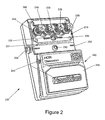
- Figure 2 is a perspective view of a pedal processor.
- Figure 3 is a perspective view of a front of a control cover for use with the pedal processor of Figure 2 .
- Figure 4 is a perspective view of the rear of the control cover shown in Figure 3 .
- Figure 5 is a plan view of the rear of the control cover shown in Figure 3 .
- Figure 6 is a cross-section of view of the control cover shown in Figure 3 taken along lines VI - VI of Figure 5 .
- Figure 7 is a perspective view of the pedal processor of Figure 2 with the control cover in place.
- Figure 8 is a perspective view of the pedal processor of Figure 2 with a rotatable control cover.
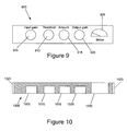
- Figure 9 is a front plan view of a rack-mountable audio processor.
- Figure 10 is a cross-sectional view of a control cover that may secure the manual controls of the audio processor shown in Figure 9 .
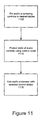
- Figure 11 is a process that may be executed using an audio processor and corresponding control cover.
- Figure 1 is a system 100 that includes a device for securing the states of electronic controls.
- System 100 includes an audio source 105.
- the audio source 105 may be an instrument, such as a guitar, a keyboard, or other instrument having a digital and/or analog output.
- the audio source 105 may also include a microphone or other transducer.
- the audio source 105 communicates audio signals in an analog and/or digital format to an audio processor 110.
- the audio processor 110 may include a plurality of manual controls 115 that adjust the processing characteristics of the audio processor 110. Manual controls 115 are adjusted by a user to place the manual controls 115 in selected states that provide the audio characteristics desired by the user.
- the audio processor 110 may include one or more audio processor types such as a compressor, preamplifier, reverb unit, effects processor, or similar audio processor.
- the audio processor 110 may be a pedal processor that includes a foot-actuated switch, a rack-mounted device, or other mechanical configuration.
- a control cover 120 is provided to cover the manual controls 115.
- the control cover 120 may substantially inhibit access to the manual controls 115 after they have been set to their selected states and/or secure the manual controls 115 in the selected states. By covering the manual controls, movement and/or inadvertent adjustment of the manual controls 115 from the selected states is substantially inhibited.
- the states of the manual controls 115 may be maintained during transportation of the audio processor 110 from one venue to another and/or during a live performance.
- System 100 may also include audio transducers, such as speakers, and/or post-processors 125.
- the transducers and/or post-processors are in communication with one or more output of the audio processor 110.
- the output of the audio processor 110 may be analog, digital, or a combination of both analog and digital signals.
- Post-processors used at 125 may also include manual controls with corresponding control covers.
- FIG 2 is a pedal processor 200 that may be used for the audio processor 110 shown in Figure 1 .
- Pedal processor may include an input 203 for communication with the audio source 105 and an output 205 for communication with the transducers/post-processors 125.
- a first area 210 of the face of the pedal processor 200 includes a plurality of manual controls 215 through 235.
- the first area 210 may include a flange 237 that substantially surrounds the plurality of manual controls 215 through 235.
- a second area 240 of the face of the pedal processor 200 may include a foot-actuated switch 245.
- the second area 240 may include visual indicia 243 indicating the type and/or more region of the processing pedal 200.
- a lamp 250 may indicate whether the processing of the pedal processor 200 is actuated or bypassed.
- Manual controls 215 through 230 are in the form of rotary controls that facilitate adjustment of the processing parameters of the pedal processor 200.
- a user rotates one or more of the manual controls 215 through 230 to angular states that may correspond to values of one or more processing parameters providing the audio characteristics desired by the user.
- Each manual control 215 through 230 may include knurling 260 to assist in the gripping the respective control and terminate at a respective flange 263 proximate a face of the pedal processor 200.
- Manual control 235 is a toggle switch that may be set to two or more switched states to alter the audio characteristics in a manner desired by the user. The toggle switch is fixed to the face of pedal processor 200 using a securement 236.
- the pedal processor 200 may be a distortion pedal for a guitar or other instrument.
- Manual control 215 may be used to adjust the level of distortion.
- Manual controls 220 and 225 may be used to adjust the low-frequency components and highfrequency components, respectively, of the output signal of the pedal processor 200.
- Manual control 230 may be used to adjust the gain of distortion provided by the pedal processor 200.
- Manual control 235 may be used to adjust the type of distortion provided by the pedal processor 200.
- Figures 3 through 6 show various views of a control cover 300 that may be used with the pedal processor 200 shown in Figure 2 .
- Figure 3 is a perspective view of one side of the control cover 300.
- the control cover 300 may include a body portion 305 and a gripping portion 310.
- the gripping portion 310 may be dimensioned to facilitate user manipulation of the control cover 300, such as its installation and/or removal to and from the pedal processor 200.
- Body portion 305 may be dimensioned to correspond to the dimensions of the second area 210 of the pedal processor 200.
- Visual indicia 315 may be provided on the control cover 300 indicative of the pedal processor 200 to which it belongs. The visual indicia 315 may allow the user to pair the control cover 300 with the corresponding pedal processor 200 and may correlate with the visual indicia 243 of the pedal processor 200.
- Figure 4 is a perspective view of another side of the control cover 300 and Figure 5 is a plan view of that side.
- the control cover 300 includes a plurality of openings 400 through 420 adapted to cover manual controls 215 through 235 of the pedal processor 200. Openings 400 through 415 are adapted to cover manual controls 215 through 230, respectively. Opening 420 is adapted to cover manual control 235.
- an additional slot 425 may be provided in opening 420 to cover the stem of the toggle switch. Slot 425 may be dimensioned to accommodate the full range of the motion of the stem through all of its selectable states.
- Additional openings 430 may be provided to accommodate fasteners on the face of the pedal processor 200 so that the fasteners do not substantially interfere with use and/or placement of the control cover 300.
- a flange 435 may substantially circumvent face 440.
- Flange 435 may be dimensioned to extend about an exterior portion of flange 237.
- FIG. 6 is a cross-sectional view of the control cover 300 taken along lines VI-VI of Figure 5 .
- opening 400 (as well as other openings 405 through 415) may include a main opening 600 dimensioned to accommodate the principal portion of manual control 215 and a base portion 605 dimensioned to accommodate flange 263 of the manual control 250.
- Opening 420 may include slot 425 dimensioned to accommodate the stem of the toggle switch 235 and a base portion 610 dimensioned to accommodate the securement 236 used to fix the toggle switch 235 to the face of the pedal processor 200.
- Openings 400 through 420 may extend partially through the body portion 305 and/or gripping portion 310 of the control cover 300. Alternatively, some or all of the openings 400 through 420 may extend completely through the body portion 305 and/or gripping portion 310 so that the states of the corresponding manual controls may be viewed.
- control cover 300 may be placed over the manual controls to prevent access to them and/or inhibit movement from the selected states.
- Control cover 300 may engage the pedal processor 200 in a number of different manners.
- a latch or other securement member may be provided to hold the control cover 300 at a position to cover the manual controls 215 through 235.
- one or more portions of the control cover 300 may be dimensioned to frictionally engage corresponding portions of the pedal processor 200.
- one or more of the openings 400 through 415 may be dimensioned to frictionally engage the outer surface of the corresponding manual control 215 through 235.
- This frictional engagement may be used to inhibit and/or prevent movement of the manual controls 215 through 235 from their selected positions. Additionally, or in the alternative, flange 435 may be dimensioned to frictionally engage flange 237 of pedal processor 200.
- Figure 7 shows the control cover 300 positioned on the pedal processor 200.
- FIG 8 shows another control cover 800 used to inhibit access to manual controls 215 through 235.
- the control cover 800 may include a shield 805 that is rotatable between first and second positions as shown by arrows 810. In the first position shown in Figure 8 , the shield 805 is in a position to expose the manual controls 215 through 235 for manipulation by a user. In the second position (not shown), the shield 805 is rotated to cover the manual controls 215 through 235 to restrict motion of manual controls by inhibiting further manipulation of the controls from their selected states.
- the shield 805 may be translucent to facilitate viewing of the states of the manual controls 215 through 235.
- the shield 805 is secured with the pedal processor 200 by one or more support arms 815.
- the support arms 815 may have a first end in fixed alignment with the pedal processor 200 and a second end in fixed alignment with the shield 805.
- the support arms 850 may be rotatable about their respective first ends to facilitate rotation of the shield 805 between the first and second positions.
- Figure 9 is a rack-mounted audio processor 900 and Figure 10 is a corresponding control cover 1000 that may be used with processor 900.
- the rack-mounted audio processor 900 of Figure 9 may be a compressor that includes a plurality of manual controls 905 through 920.
- Control 905 may control input gain to the compressor.
- Control 910 may be used to adjust the threshold at which the compressor begins its compression operation.
- Control 915 may be used to set the amount of compression
- control 920 may be used to adjust the output gain of the compressor.
- a meter 925 may be used to monitor the input signal level, the output signal level, and/or the amount of compression.
- Control cover 1000 includes a plurality of openings 1005 through 1020 that are dimensioned to accommodate manual controls 905 through 920.
- One or more of the openings 1005 through 1020 may frictionally engage the corresponding manual controls 905 through 920 to secure the control cover 1000 with the rack-mounted processor 900.
- elastic latches and/or flanges 1025 may be provided to engage a face of the rack-mounted processor 900.
- control cover 1000 may include an opening 1030 through which meter 925 may be viewed. Opening 1030 may be entirely exposed meter 925 or be provided with a translucent cover through which the meter 925 may be viewed. Similarly, openings 1005 through 1020 may extend completely through the cover 1000 to expose the corresponding manual controls 905 through 920. Translucent covers may also be provided over openings 1005 through 1020 to facilitate viewing.
- Audio processors may have exposed surfaces that may be subject to damage during use and/or transport. Some of these surfaces may include aesthetically pleasing designs, colored surfaces, indicia indicative of functions executed by the audio processor and/or certain controls, or similar surfaces. Accordingly, the corresponding control cover may be dimensioned to cover areas of the audio processor proximate and/or beyond the area of the manual controls. In such instances, the control cover may protect these areas from scratching or other damage that may occur during use and/or transport of the audio processor.
- Figure 11 is a method corresponding to use of a control cover in conjunction with an audio processor.
- the audio processing controls of the audio processor are set to the desired states by the user.
- the desired states of the audio controls are protected using a control cover.
- the audio processor is used with the selected control states at 1115.
Landscapes
- Engineering & Computer Science (AREA)
- Physics & Mathematics (AREA)
- Acoustics & Sound (AREA)
- Multimedia (AREA)
- General Physics & Mathematics (AREA)
- Automation & Control Theory (AREA)
- Signal Processing (AREA)
- Circuit For Audible Band Transducer (AREA)
- Electrophonic Musical Instruments (AREA)
- Fittings On The Vehicle Exterior For Carrying Loads, And Devices For Holding Or Mounting Articles (AREA)
- Control Of Amplification And Gain Control (AREA)
Abstract
Description
- The present application is directed to a system including a device for securing the states of electronic controls, such as the controls of an audio processing unit.
- Audio processors are used in a wide range of applications. The audio processors may include those used in studios as well as live performance venues. Pedal processors, such as bass guitar pedals, electric guitar pedals, acoustic guitar pedals, amplifier pedals, keyboard pedals, and other pedal processor types are used to control the audio characteristics of the audio ultimately produced by the respective instrument. Other audio processors include rack-mounted microphone/instrument preamplifiers, compressors, reverb processors, effects processors, and similar audio processor types.
- Pedal processors may have controls that are manually adjustable to selected states to provide desired audio processing characteristics. A guitarist or other performer may have a particular set of adjustments to provide the desired characteristics. During a performance, however, the states of the controls may be upset through physical contact that may be ancillary to the performance. The states of the controls may also be disturbed during transportation of the pedal processor from one venue to another.
- Rack-mounted processors may also have controls that are manually adjustable to selected states to provide desired audio processing characteristics. A studio and/or live mix engineer may have a particular set of control adjustments that are used to provide the desired audio characteristic. The engineer may find it difficult to maintain the control adjustments during the performance. The states of the controls may also be disturbed during transportation of the rack-mounted processors from one venue to another.
- A system comprises an audio processor adapted for communication with an audio source and a control cover. The audio processor may have a plurality of manual controls to adjust audio processing parameters based on selected states of the controls. The control cover may engage the audio processor to restrict movement of the manual controls and maintain the manual controls in their selected states. The audio processor may be a pedal-processor.
- Other systems, methods, features and advantages of the invention will be, or will become, apparent to one with skill in the art upon examination of the following figures and detailed description. It is intended that all such additional systems, methods, features and advantages be included within this description, be within the scope of the invention, and be protected by the following claims.
- The invention can be better understood with reference to the following drawings and description. The components in the figures are not necessarily to scale, emphasis instead being placed upon illustrating the principles of the invention. Moreover, in the figures, like referenced numerals designate corresponding parts throughout the different views.
-
Figure 1 is an audio system including a device for securing the states of electronic controls. -
Figure 2 is a perspective view of a pedal processor. -
Figure 3 is a perspective view of a front of a control cover for use with the pedal processor ofFigure 2 . -
Figure 4 is a perspective view of the rear of the control cover shown inFigure 3 . -
Figure 5 is a plan view of the rear of the control cover shown inFigure 3 . -
Figure 6 is a cross-section of view of the control cover shown inFigure 3 taken along lines VI - VI ofFigure 5 . -
Figure 7 is a perspective view of the pedal processor ofFigure 2 with the control cover in place. -
Figure 8 is a perspective view of the pedal processor ofFigure 2 with a rotatable control cover. -
Figure 9 is a front plan view of a rack-mountable audio processor. -
Figure 10 is a cross-sectional view of a control cover that may secure the manual controls of the audio processor shown inFigure 9 . -
Figure 11 is a process that may be executed using an audio processor and corresponding control cover. -
Figure 1 is asystem 100 that includes a device for securing the states of electronic controls.System 100 includes anaudio source 105. Theaudio source 105 may be an instrument, such as a guitar, a keyboard, or other instrument having a digital and/or analog output. Theaudio source 105 may also include a microphone or other transducer. Theaudio source 105 communicates audio signals in an analog and/or digital format to anaudio processor 110. Theaudio processor 110 may include a plurality ofmanual controls 115 that adjust the processing characteristics of theaudio processor 110.Manual controls 115 are adjusted by a user to place themanual controls 115 in selected states that provide the audio characteristics desired by the user. - The
audio processor 110 may include one or more audio processor types such as a compressor, preamplifier, reverb unit, effects processor, or similar audio processor. Mechanically, theaudio processor 110 may be a pedal processor that includes a foot-actuated switch, a rack-mounted device, or other mechanical configuration. - A
control cover 120 is provided to cover themanual controls 115. Thecontrol cover 120 may substantially inhibit access to themanual controls 115 after they have been set to their selected states and/or secure themanual controls 115 in the selected states. By covering the manual controls, movement and/or inadvertent adjustment of themanual controls 115 from the selected states is substantially inhibited. Depending on the particular configuration of thecontrol cover 120, the states of themanual controls 115 may be maintained during transportation of theaudio processor 110 from one venue to another and/or during a live performance. -
System 100 may also include audio transducers, such as speakers, and/or post-processors 125. The transducers and/or post-processors are in communication with one or more output of theaudio processor 110. The output of theaudio processor 110 may be analog, digital, or a combination of both analog and digital signals. Post-processors used at 125 may also include manual controls with corresponding control covers. -
Figure 2 is apedal processor 200 that may be used for theaudio processor 110 shown inFigure 1 . Pedal processor may include aninput 203 for communication with theaudio source 105 and anoutput 205 for communication with the transducers/post-processors 125. Afirst area 210 of the face of thepedal processor 200 includes a plurality ofmanual controls 215 through 235. Thefirst area 210 may include aflange 237 that substantially surrounds the plurality ofmanual controls 215 through 235. Asecond area 240 of the face of thepedal processor 200 may include a foot-actuatedswitch 245. Thesecond area 240 may includevisual indicia 243 indicating the type and/or more region of theprocessing pedal 200. Alamp 250 may indicate whether the processing of thepedal processor 200 is actuated or bypassed. -
Manual controls 215 through 230 are in the form of rotary controls that facilitate adjustment of the processing parameters of thepedal processor 200. A user rotates one or more of themanual controls 215 through 230 to angular states that may correspond to values of one or more processing parameters providing the audio characteristics desired by the user. Eachmanual control 215 through 230 may include knurling 260 to assist in the gripping the respective control and terminate at arespective flange 263 proximate a face of thepedal processor 200.Manual control 235 is a toggle switch that may be set to two or more switched states to alter the audio characteristics in a manner desired by the user. The toggle switch is fixed to the face ofpedal processor 200 using asecurement 236. - In
Figure 2 , thepedal processor 200 may be a distortion pedal for a guitar or other instrument.Manual control 215 may be used to adjust the level of distortion. Manual controls 220 and 225 may be used to adjust the low-frequency components and highfrequency components, respectively, of the output signal of thepedal processor 200.Manual control 230 may be used to adjust the gain of distortion provided by thepedal processor 200.Manual control 235 may be used to adjust the type of distortion provided by thepedal processor 200. -
Figures 3 through 6 show various views of acontrol cover 300 that may be used with thepedal processor 200 shown inFigure 2 .Figure 3 is a perspective view of one side of thecontrol cover 300. Thecontrol cover 300 may include abody portion 305 and agripping portion 310. The grippingportion 310 may be dimensioned to facilitate user manipulation of thecontrol cover 300, such as its installation and/or removal to and from thepedal processor 200.Body portion 305 may be dimensioned to correspond to the dimensions of thesecond area 210 of thepedal processor 200.Visual indicia 315 may be provided on thecontrol cover 300 indicative of thepedal processor 200 to which it belongs. Thevisual indicia 315 may allow the user to pair thecontrol cover 300 with the correspondingpedal processor 200 and may correlate with thevisual indicia 243 of thepedal processor 200. -
Figure 4 is a perspective view of another side of thecontrol cover 300 andFigure 5 is a plan view of that side. As shown, thecontrol cover 300 includes a plurality ofopenings 400 through 420 adapted to covermanual controls 215 through 235 of thepedal processor 200.Openings 400 through 415 are adapted to covermanual controls 215 through 230, respectively.Opening 420 is adapted to covermanual control 235. In those instances in which themanual control 235 is a toggle switch, anadditional slot 425 may be provided inopening 420 to cover the stem of the toggle switch.Slot 425 may be dimensioned to accommodate the full range of the motion of the stem through all of its selectable states.Additional openings 430 may be provided to accommodate fasteners on the face of thepedal processor 200 so that the fasteners do not substantially interfere with use and/or placement of thecontrol cover 300. Aflange 435 may substantially circumventface 440.Flange 435 may be dimensioned to extend about an exterior portion offlange 237. -
Figure 6 is a cross-sectional view of thecontrol cover 300 taken along lines VI-VI ofFigure 5 . As shown, opening 400 (as well asother openings 405 through 415) may include amain opening 600 dimensioned to accommodate the principal portion ofmanual control 215 and abase portion 605 dimensioned to accommodateflange 263 of themanual control 250. Opening 420 may includeslot 425 dimensioned to accommodate the stem of thetoggle switch 235 and abase portion 610 dimensioned to accommodate thesecurement 236 used to fix thetoggle switch 235 to the face of thepedal processor 200.Openings 400 through 420 may extend partially through thebody portion 305 and/or grippingportion 310 of thecontrol cover 300. Alternatively, some or all of theopenings 400 through 420 may extend completely through thebody portion 305 and/or grippingportion 310 so that the states of the corresponding manual controls may be viewed. - Once the manual controls 215 through 235 have been set to the desired selected states, the
control cover 300 may be placed over the manual controls to prevent access to them and/or inhibit movement from the selected states.Control cover 300 may engage thepedal processor 200 in a number of different manners. A latch or other securement member may be provided to hold thecontrol cover 300 at a position to cover the manual controls 215 through 235. Additionally, or in the alternative, one or more portions of thecontrol cover 300 may be dimensioned to frictionally engage corresponding portions of thepedal processor 200. For example, one or more of theopenings 400 through 415 may be dimensioned to frictionally engage the outer surface of the correspondingmanual control 215 through 235. This frictional engagement may be used to inhibit and/or prevent movement of themanual controls 215 through 235 from their selected positions. Additionally, or in the alternative,flange 435 may be dimensioned to frictionally engageflange 237 ofpedal processor 200.Figure 7 shows thecontrol cover 300 positioned on thepedal processor 200. -
Figure 8 shows anothercontrol cover 800 used to inhibit access tomanual controls 215 through 235. Thecontrol cover 800 may include ashield 805 that is rotatable between first and second positions as shown byarrows 810. In the first position shown inFigure 8 , theshield 805 is in a position to expose the manual controls 215 through 235 for manipulation by a user. In the second position (not shown), theshield 805 is rotated to cover the manual controls 215 through 235 to restrict motion of manual controls by inhibiting further manipulation of the controls from their selected states. Theshield 805 may be translucent to facilitate viewing of the states of themanual controls 215 through 235. InFigure 8 , theshield 805 is secured with thepedal processor 200 by one ormore support arms 815. Thesupport arms 815 may have a first end in fixed alignment with thepedal processor 200 and a second end in fixed alignment with theshield 805. The support arms 850 may be rotatable about their respective first ends to facilitate rotation of theshield 805 between the first and second positions. -
Figure 9 is a rack-mountedaudio processor 900 andFigure 10 is acorresponding control cover 1000 that may be used withprocessor 900. Although other rack-mounted audio processors may be used, the rack-mountedaudio processor 900 ofFigure 9 may be a compressor that includes a plurality ofmanual controls 905 through 920.Control 905 may control input gain to the compressor.Control 910 may be used to adjust the threshold at which the compressor begins its compression operation.Control 915 may be used to set the amount of compression, andcontrol 920 may be used to adjust the output gain of the compressor. Ameter 925 may be used to monitor the input signal level, the output signal level, and/or the amount of compression. -
Control cover 1000 includes a plurality ofopenings 1005 through 1020 that are dimensioned to accommodatemanual controls 905 through 920. One or more of theopenings 1005 through 1020 may frictionally engage the correspondingmanual controls 905 through 920 to secure thecontrol cover 1000 with the rack-mountedprocessor 900. Additionally, or in the alternative, elastic latches and/orflanges 1025 may be provided to engage a face of the rack-mountedprocessor 900. - It may be desirable to monitor the rack-mounted
processor 900 during its operation.Meter 925 may be used for this purpose. Accordingly,control cover 1000 may include anopening 1030 through whichmeter 925 may be viewed.Opening 1030 may be entirely exposedmeter 925 or be provided with a translucent cover through which themeter 925 may be viewed. Similarly,openings 1005 through 1020 may extend completely through thecover 1000 to expose the correspondingmanual controls 905 through 920. Translucent covers may also be provided overopenings 1005 through 1020 to facilitate viewing. - Audio processors may have exposed surfaces that may be subject to damage during use and/or transport. Some of these surfaces may include aesthetically pleasing designs, colored surfaces, indicia indicative of functions executed by the audio processor and/or certain controls, or similar surfaces. Accordingly, the corresponding control cover may be dimensioned to cover areas of the audio processor proximate and/or beyond the area of the manual controls. In such instances, the control cover may protect these areas from scratching or other damage that may occur during use and/or transport of the audio processor.
-
Figure 11 is a method corresponding to use of a control cover in conjunction with an audio processor. At 1105, the audio processing controls of the audio processor are set to the desired states by the user. At 1110, the desired states of the audio controls are protected using a control cover. The audio processor is used with the selected control states at 1115. - While various embodiments of the invention have been described, it will be apparent to those of ordinary skill in the art that many more embodiments and implementations are possible within the scope of the invention. Accordingly, the invention is not to be restricted except in light of the attached claims and their equivalents.
Claims (15)
- A system comprising:an audio processor adapted for communication with an audio source, where the audio processor has a plurality of manual controls to adjust audio processing parameters based on selected states of the plurality of manual controls; anda control cover adapted to engage the audio processor, where the control cover is adapted to restrict movement of the plurality of manual controls to maintain the plurality of manual controls in the selected states.
- The system of claim 1, where the control cover comprises:a body portion; anda plurality of openings disposed in the body portion positioned to frictionally engage corresponding controls of the plurality of manual controls; and/orvisual indicia indicative of the audio processor for which the control cover is designed and/ora shield rotatable between a first position allowing access to the plurality of manual controls and a second position substantially preventing access to the plurality of manual controls.
- The system of claim 2, where the audio processor comprises a flange substantially surrounding the plurality of manual controls, and where the body portion comprises a flange frictionally engaging the flange of the audio processor; and/or
a guitar pedal having a first area including the plurality of manual controls and a second area comprising a foot actuated switch. - The system of claim 2, further comprising:a manual grip extending from the body portion; and/ora support arm having a first end in fixed alignment with the audio processor and a second end in fixed alignment with the shield, where the support arm is rotatable about the first end to facilitate rotation of the shield between the first and second positions; and/orwhere the shield comprises a translucent portion that facilitates viewing of the plurality of manual controls when the shield is in the second position.
- A system comprising:a pedal processor having a first area including a plurality of manual controls and a second area comprising a foot actuated switch, where the plurality of manual controls are manipulated to selected states to adjust audio processing parameters of the pedal processor; anda control cover adapted for engagement with the pedal processor, where the control cover is adapted to restrict movement of the plurality of manual controls to maintain the selected states of the plurality of manual controls.
- The system of claim 5, where the control cover comprises:a body portion; anda plurality of openings disposed in the body portion positioned to frictionally engage corresponding controls of the plurality of manual controls; and/ora manual grip extending from the body portion.
- The system of claim 6, where the pedal processor comprises:a flange substantially surrounding the plurality of manual controls, and where the body portion comprises a flange frictionally engaging the flange of the pedal processor; and/ora guitar pedal.
- The system of claim 5, where the control cover comprises:visual indicia indicative of the pedal processor for which the control cover is designed; and/ora shield rotatable between a first position allowing access to the plurality of manual controls and a second position substantially preventing access to the plurality of manual controls.
- The system of claim 8, where the shield comprises a translucent portion that facilitates viewing of the plurality of manual controls when the shield is in the second position.
- A control cover for use with a pedal processor, the pedal processor having a first area including a plurality of manual controls and a second area comprising a foot actuated switch, where the plurality of manual controls are manipulated to selected positions to adjust audio processing parameters of the pedal processor, the control cover comprising:a body portion; anda plurality of openings disposed in the body portion positioned to substantially inhibit access to corresponding controls of the plurality of manual controls.
- The control cover of claim 10, where the plurality of openings are dimensioned to allow the body portion to frictionally engage one or more of the plurality of manual controls; and/or
where the pedal processor comprises a flange substantially surrounding the plurality of manual controls, and where the body portion comprises a flange frictionally engaging the flange of the pedal processor; and/or
where the control cover comprises visual indicia indicative of the pedal processor for which the control cover is designed. - A system for use with an audio processor comprising a control cover adapted for engagement with the audio processor, where the control cover is adapted to restrict movement of a plurality of manual controls of the audio processor to maintain the selected states of the plurality of manual controls.
- The system of claim 12, where the control cover comprises:a body portion;a plurality of openings disposed in the body portion positioned to frictionally engage corresponding controls of the plurality of manual controls; and/orwhere the audio processor comprises a pedal processor.
- An apparatus for use with an audio processor comprising a cover adapted for removable engagement with the audio processor, where the control cover is dimensioned to protect one or more surfaces of the audio processor.
- The apparatus of claim 14, where the cover comprises:a body portion; anda plurality of openings disposed in the body portion positioned to frictionally engage corresponding controls of a plurality of manual controls of the audio processor; and/orwhere the audio processor comprises a pedal processor.
Applications Claiming Priority (1)
| Application Number | Priority Date | Filing Date | Title |
|---|---|---|---|
| US12/104,975 US8483404B2 (en) | 2008-04-17 | 2008-04-17 | System including device for securing the states of electronic controls |
Publications (2)
| Publication Number | Publication Date |
|---|---|
| EP2110730A1 true EP2110730A1 (en) | 2009-10-21 |
| EP2110730B1 EP2110730B1 (en) | 2012-01-04 |
Family
ID=40902657
Family Applications (1)
| Application Number | Title | Priority Date | Filing Date |
|---|---|---|---|
| EP09005472A Not-in-force EP2110730B1 (en) | 2008-04-17 | 2009-04-17 | System including device for securing the states of electronic controls |
Country Status (3)
| Country | Link |
|---|---|
| US (1) | US8483404B2 (en) |
| EP (1) | EP2110730B1 (en) |
| AT (1) | ATE540349T1 (en) |
Cited By (2)
| Publication number | Priority date | Publication date | Assignee | Title |
|---|---|---|---|---|
| FR3002660A1 (en) * | 2013-02-22 | 2014-08-29 | Karim Messadek | PROTECTIVE DEVICES FOR ROTARY CONTROL BUTTONS |
| US9817430B2 (en) | 2013-02-22 | 2017-11-14 | Karim Messadek | Protective apparatuses for rotary control knobs |
Families Citing this family (2)
| Publication number | Priority date | Publication date | Assignee | Title |
|---|---|---|---|---|
| US10151464B2 (en) | 2012-09-18 | 2018-12-11 | Michael John Ahern | User-actuated lighting effect device |
| USD789896S1 (en) * | 2015-11-11 | 2017-06-20 | Michael John Ahern | User-actuated lighting effect device |
Citations (3)
| Publication number | Priority date | Publication date | Assignee | Title |
|---|---|---|---|---|
| US4623992A (en) | 1982-12-06 | 1986-11-18 | Pioneer Electronic Corporation | Operating panel for electronic audio equipment |
| US6215055B1 (en) | 1997-08-06 | 2001-04-10 | Darren Saravis | Foot pedal boards for musical instruments |
| EP1435766A1 (en) | 2002-12-30 | 2004-07-07 | Motorola, Inc. | Portable electronic device housing |
Family Cites Families (8)
| Publication number | Priority date | Publication date | Assignee | Title |
|---|---|---|---|---|
| US2833158A (en) * | 1955-05-26 | 1958-05-06 | Raytheon Mfg Co | Knob locking devices |
| GB919989A (en) * | 1960-11-02 | 1963-02-27 | Wipac Dev Ltd | Improvements in control knobs for rotatable members |
| DE2454154B2 (en) * | 1974-11-14 | 1977-05-12 | E. DoId & Söhne KG, 7743 Furtwangen | ENCLOSURES FOR ELECTRIC AND ELECTRONIC SWITCHGEAR |
| US4733806A (en) * | 1980-03-26 | 1988-03-29 | Sloop Conrad B | Case |
| US4445415A (en) * | 1982-08-18 | 1984-05-01 | Izquierdo George J | Portable case and stand for pedal controls operationally fixed therein for use with a keyboard temporarily mountable thereon |
| CA1274184A (en) * | 1986-10-07 | 1990-09-18 | Edward S. Kroetsch | Modular hearing aid with lid hinged to faceplate |
| US5866829A (en) * | 1996-12-20 | 1999-02-02 | Pecoraro; Thomas | Pedal rack |
| US7546920B1 (en) * | 2006-09-25 | 2009-06-16 | Cannon Safe Inc. | Rifle travel case |
-
2008
- 2008-04-17 US US12/104,975 patent/US8483404B2/en active Active
-
2009
- 2009-04-17 AT AT09005472T patent/ATE540349T1/en active
- 2009-04-17 EP EP09005472A patent/EP2110730B1/en not_active Not-in-force
Patent Citations (3)
| Publication number | Priority date | Publication date | Assignee | Title |
|---|---|---|---|---|
| US4623992A (en) | 1982-12-06 | 1986-11-18 | Pioneer Electronic Corporation | Operating panel for electronic audio equipment |
| US6215055B1 (en) | 1997-08-06 | 2001-04-10 | Darren Saravis | Foot pedal boards for musical instruments |
| EP1435766A1 (en) | 2002-12-30 | 2004-07-07 | Motorola, Inc. | Portable electronic device housing |
Cited By (2)
| Publication number | Priority date | Publication date | Assignee | Title |
|---|---|---|---|---|
| FR3002660A1 (en) * | 2013-02-22 | 2014-08-29 | Karim Messadek | PROTECTIVE DEVICES FOR ROTARY CONTROL BUTTONS |
| US9817430B2 (en) | 2013-02-22 | 2017-11-14 | Karim Messadek | Protective apparatuses for rotary control knobs |
Also Published As
| Publication number | Publication date |
|---|---|
| US8483404B2 (en) | 2013-07-09 |
| US20090262953A1 (en) | 2009-10-22 |
| EP2110730B1 (en) | 2012-01-04 |
| ATE540349T1 (en) | 2012-01-15 |
Similar Documents
| Publication | Publication Date | Title |
|---|---|---|
| US7015390B1 (en) | Triad pickup | |
| US20150201255A1 (en) | Portable Studio Monitor System | |
| US7162046B2 (en) | Microphone-tailored equalizing system | |
| US20140224099A1 (en) | System and method for sound augmentation of acoustic musical instruments | |
| US6680431B2 (en) | Violin shoulder rest | |
| US8483404B2 (en) | System including device for securing the states of electronic controls | |
| US7297863B2 (en) | Electro-acoustically amplified drum mixer | |
| EP2639787B1 (en) | Signal processing apparatus for stringed instrument | |
| WO2006073990A3 (en) | Integrated multimedia signal processing system using centralized processing of signals | |
| JP4295798B2 (en) | Mixing apparatus, method, and program | |
| CN107948869B (en) | Audio processing method, audio processing device, audio system, and storage medium | |
| US9424824B2 (en) | System and method for sound augmentation of acoustic musical instruments | |
| GB2525041A (en) | Sound capture method and apparatus | |
| JP2008160588A (en) | Audio signal processing apparatus, audio signal processing method, and imaging apparatus | |
| US20040159225A1 (en) | Sound pickup system for acoustic string instruments | |
| US8023665B2 (en) | Microphone-tailored equalizing system | |
| Böhm et al. | A multi-channel anechoic orchestra recording of Beethoven’s Symphony no. 8 op. 93 | |
| US9704465B2 (en) | System and method for sound augmentation of acoustic musical instruments | |
| US7718886B1 (en) | Sensor assembly for stringed musical instruments | |
| JP5671894B2 (en) | Acoustic adjustment support method, acoustic adjustment support device, and program | |
| JP2009139730A (en) | Musical signal output device and string musical instrument | |
| JPH0833091A (en) | Howling prediction device | |
| EP1446874B1 (en) | Microphone-tailored equalizing system | |
| CA2445955C (en) | Microphone-tailored equalizing system | |
| US11330362B2 (en) | Acoustic device |
Legal Events
| Date | Code | Title | Description |
|---|---|---|---|
| PUAI | Public reference made under article 153(3) epc to a published international application that has entered the european phase |
Free format text: ORIGINAL CODE: 0009012 |
|
| AK | Designated contracting states |
Kind code of ref document: A1 Designated state(s): AT BE BG CH CY CZ DE DK EE ES FI FR GB GR HR HU IE IS IT LI LT LU LV MC MK MT NL NO PL PT RO SE SI SK TR |
|
| 17P | Request for examination filed |
Effective date: 20100331 |
|
| 17Q | First examination report despatched |
Effective date: 20100505 |
|
| GRAP | Despatch of communication of intention to grant a patent |
Free format text: ORIGINAL CODE: EPIDOSNIGR1 |
|
| GRAS | Grant fee paid |
Free format text: ORIGINAL CODE: EPIDOSNIGR3 |
|
| GRAA | (expected) grant |
Free format text: ORIGINAL CODE: 0009210 |
|
| AK | Designated contracting states |
Kind code of ref document: B1 Designated state(s): AT BE BG CH CY CZ DE DK EE ES FI FR GB GR HR HU IE IS IT LI LT LU LV MC MK MT NL NO PL PT RO SE SI SK TR |
|
| REG | Reference to a national code |
Ref country code: GB Ref legal event code: FG4D |
|
| REG | Reference to a national code |
Ref country code: CH Ref legal event code: EP |
|
| REG | Reference to a national code |
Ref country code: AT Ref legal event code: REF Ref document number: 540349 Country of ref document: AT Kind code of ref document: T Effective date: 20120115 |
|
| REG | Reference to a national code |
Ref country code: IE Ref legal event code: FG4D |
|
| REG | Reference to a national code |
Ref country code: DE Ref legal event code: R096 Ref document number: 602009004455 Country of ref document: DE Effective date: 20120308 |
|
| REG | Reference to a national code |
Ref country code: NL Ref legal event code: VDEP Effective date: 20120104 |
|
| PG25 | Lapsed in a contracting state [announced via postgrant information from national office to epo] |
Ref country code: SI Free format text: LAPSE BECAUSE OF FAILURE TO SUBMIT A TRANSLATION OF THE DESCRIPTION OR TO PAY THE FEE WITHIN THE PRESCRIBED TIME-LIMIT Effective date: 20120104 |
|
| LTIE | Lt: invalidation of european patent or patent extension |
Effective date: 20120104 |
|
| PG25 | Lapsed in a contracting state [announced via postgrant information from national office to epo] |
Ref country code: BG Free format text: LAPSE BECAUSE OF FAILURE TO SUBMIT A TRANSLATION OF THE DESCRIPTION OR TO PAY THE FEE WITHIN THE PRESCRIBED TIME-LIMIT Effective date: 20120404 Ref country code: NL Free format text: LAPSE BECAUSE OF FAILURE TO SUBMIT A TRANSLATION OF THE DESCRIPTION OR TO PAY THE FEE WITHIN THE PRESCRIBED TIME-LIMIT Effective date: 20120104 Ref country code: NO Free format text: LAPSE BECAUSE OF FAILURE TO SUBMIT A TRANSLATION OF THE DESCRIPTION OR TO PAY THE FEE WITHIN THE PRESCRIBED TIME-LIMIT Effective date: 20120404 Ref country code: LT Free format text: LAPSE BECAUSE OF FAILURE TO SUBMIT A TRANSLATION OF THE DESCRIPTION OR TO PAY THE FEE WITHIN THE PRESCRIBED TIME-LIMIT Effective date: 20120104 Ref country code: IS Free format text: LAPSE BECAUSE OF FAILURE TO SUBMIT A TRANSLATION OF THE DESCRIPTION OR TO PAY THE FEE WITHIN THE PRESCRIBED TIME-LIMIT Effective date: 20120504 Ref country code: BE Free format text: LAPSE BECAUSE OF FAILURE TO SUBMIT A TRANSLATION OF THE DESCRIPTION OR TO PAY THE FEE WITHIN THE PRESCRIBED TIME-LIMIT Effective date: 20120104 Ref country code: HR Free format text: LAPSE BECAUSE OF FAILURE TO SUBMIT A TRANSLATION OF THE DESCRIPTION OR TO PAY THE FEE WITHIN THE PRESCRIBED TIME-LIMIT Effective date: 20120104 |
|
| PG25 | Lapsed in a contracting state [announced via postgrant information from national office to epo] |
Ref country code: PL Free format text: LAPSE BECAUSE OF FAILURE TO SUBMIT A TRANSLATION OF THE DESCRIPTION OR TO PAY THE FEE WITHIN THE PRESCRIBED TIME-LIMIT Effective date: 20120104 Ref country code: GR Free format text: LAPSE BECAUSE OF FAILURE TO SUBMIT A TRANSLATION OF THE DESCRIPTION OR TO PAY THE FEE WITHIN THE PRESCRIBED TIME-LIMIT Effective date: 20120405 Ref country code: FI Free format text: LAPSE BECAUSE OF FAILURE TO SUBMIT A TRANSLATION OF THE DESCRIPTION OR TO PAY THE FEE WITHIN THE PRESCRIBED TIME-LIMIT Effective date: 20120104 Ref country code: PT Free format text: LAPSE BECAUSE OF FAILURE TO SUBMIT A TRANSLATION OF THE DESCRIPTION OR TO PAY THE FEE WITHIN THE PRESCRIBED TIME-LIMIT Effective date: 20120504 Ref country code: LV Free format text: LAPSE BECAUSE OF FAILURE TO SUBMIT A TRANSLATION OF THE DESCRIPTION OR TO PAY THE FEE WITHIN THE PRESCRIBED TIME-LIMIT Effective date: 20120104 |
|
| REG | Reference to a national code |
Ref country code: AT Ref legal event code: MK05 Ref document number: 540349 Country of ref document: AT Kind code of ref document: T Effective date: 20120104 |
|
| PG25 | Lapsed in a contracting state [announced via postgrant information from national office to epo] |
Ref country code: CY Free format text: LAPSE BECAUSE OF FAILURE TO SUBMIT A TRANSLATION OF THE DESCRIPTION OR TO PAY THE FEE WITHIN THE PRESCRIBED TIME-LIMIT Effective date: 20120104 |
|
| PG25 | Lapsed in a contracting state [announced via postgrant information from national office to epo] |
Ref country code: CZ Free format text: LAPSE BECAUSE OF FAILURE TO SUBMIT A TRANSLATION OF THE DESCRIPTION OR TO PAY THE FEE WITHIN THE PRESCRIBED TIME-LIMIT Effective date: 20120104 Ref country code: DK Free format text: LAPSE BECAUSE OF FAILURE TO SUBMIT A TRANSLATION OF THE DESCRIPTION OR TO PAY THE FEE WITHIN THE PRESCRIBED TIME-LIMIT Effective date: 20120104 Ref country code: SE Free format text: LAPSE BECAUSE OF FAILURE TO SUBMIT A TRANSLATION OF THE DESCRIPTION OR TO PAY THE FEE WITHIN THE PRESCRIBED TIME-LIMIT Effective date: 20120104 Ref country code: EE Free format text: LAPSE BECAUSE OF FAILURE TO SUBMIT A TRANSLATION OF THE DESCRIPTION OR TO PAY THE FEE WITHIN THE PRESCRIBED TIME-LIMIT Effective date: 20120104 Ref country code: RO Free format text: LAPSE BECAUSE OF FAILURE TO SUBMIT A TRANSLATION OF THE DESCRIPTION OR TO PAY THE FEE WITHIN THE PRESCRIBED TIME-LIMIT Effective date: 20120104 |
|
| PLBE | No opposition filed within time limit |
Free format text: ORIGINAL CODE: 0009261 |
|
| STAA | Information on the status of an ep patent application or granted ep patent |
Free format text: STATUS: NO OPPOSITION FILED WITHIN TIME LIMIT |
|
| PG25 | Lapsed in a contracting state [announced via postgrant information from national office to epo] |
Ref country code: MC Free format text: LAPSE BECAUSE OF NON-PAYMENT OF DUE FEES Effective date: 20120430 Ref country code: IT Free format text: LAPSE BECAUSE OF FAILURE TO SUBMIT A TRANSLATION OF THE DESCRIPTION OR TO PAY THE FEE WITHIN THE PRESCRIBED TIME-LIMIT Effective date: 20120104 Ref country code: SK Free format text: LAPSE BECAUSE OF FAILURE TO SUBMIT A TRANSLATION OF THE DESCRIPTION OR TO PAY THE FEE WITHIN THE PRESCRIBED TIME-LIMIT Effective date: 20120104 |
|
| 26N | No opposition filed |
Effective date: 20121005 |
|
| REG | Reference to a national code |
Ref country code: IE Ref legal event code: MM4A |
|
| PG25 | Lapsed in a contracting state [announced via postgrant information from national office to epo] |
Ref country code: IE Free format text: LAPSE BECAUSE OF NON-PAYMENT OF DUE FEES Effective date: 20120417 Ref country code: AT Free format text: LAPSE BECAUSE OF FAILURE TO SUBMIT A TRANSLATION OF THE DESCRIPTION OR TO PAY THE FEE WITHIN THE PRESCRIBED TIME-LIMIT Effective date: 20120104 |
|
| REG | Reference to a national code |
Ref country code: DE Ref legal event code: R097 Ref document number: 602009004455 Country of ref document: DE Effective date: 20121005 |
|
| PG25 | Lapsed in a contracting state [announced via postgrant information from national office to epo] |
Ref country code: MK Free format text: LAPSE BECAUSE OF FAILURE TO SUBMIT A TRANSLATION OF THE DESCRIPTION OR TO PAY THE FEE WITHIN THE PRESCRIBED TIME-LIMIT Effective date: 20120104 |
|
| PG25 | Lapsed in a contracting state [announced via postgrant information from national office to epo] |
Ref country code: ES Free format text: LAPSE BECAUSE OF FAILURE TO SUBMIT A TRANSLATION OF THE DESCRIPTION OR TO PAY THE FEE WITHIN THE PRESCRIBED TIME-LIMIT Effective date: 20120415 |
|
| PG25 | Lapsed in a contracting state [announced via postgrant information from national office to epo] |
Ref country code: MT Free format text: LAPSE BECAUSE OF FAILURE TO SUBMIT A TRANSLATION OF THE DESCRIPTION OR TO PAY THE FEE WITHIN THE PRESCRIBED TIME-LIMIT Effective date: 20120104 |
|
| PGFP | Annual fee paid to national office [announced via postgrant information from national office to epo] |
Ref country code: DE Payment date: 20130429 Year of fee payment: 5 Ref country code: GB Payment date: 20130429 Year of fee payment: 5 |
|
| PGFP | Annual fee paid to national office [announced via postgrant information from national office to epo] |
Ref country code: FR Payment date: 20130506 Year of fee payment: 5 |
|
| REG | Reference to a national code |
Ref country code: CH Ref legal event code: PL |
|
| PG25 | Lapsed in a contracting state [announced via postgrant information from national office to epo] |
Ref country code: LI Free format text: LAPSE BECAUSE OF NON-PAYMENT OF DUE FEES Effective date: 20130430 Ref country code: CH Free format text: LAPSE BECAUSE OF NON-PAYMENT OF DUE FEES Effective date: 20130430 |
|
| PG25 | Lapsed in a contracting state [announced via postgrant information from national office to epo] |
Ref country code: TR Free format text: LAPSE BECAUSE OF FAILURE TO SUBMIT A TRANSLATION OF THE DESCRIPTION OR TO PAY THE FEE WITHIN THE PRESCRIBED TIME-LIMIT Effective date: 20120104 |
|
| PG25 | Lapsed in a contracting state [announced via postgrant information from national office to epo] |
Ref country code: LU Free format text: LAPSE BECAUSE OF NON-PAYMENT OF DUE FEES Effective date: 20120417 |
|
| PG25 | Lapsed in a contracting state [announced via postgrant information from national office to epo] |
Ref country code: HU Free format text: LAPSE BECAUSE OF FAILURE TO SUBMIT A TRANSLATION OF THE DESCRIPTION OR TO PAY THE FEE WITHIN THE PRESCRIBED TIME-LIMIT Effective date: 20090417 |
|
| REG | Reference to a national code |
Ref country code: DE Ref legal event code: R119 Ref document number: 602009004455 Country of ref document: DE |
|
| GBPC | Gb: european patent ceased through non-payment of renewal fee |
Effective date: 20140417 |
|
| REG | Reference to a national code |
Ref country code: FR Ref legal event code: ST Effective date: 20141231 |
|
| PG25 | Lapsed in a contracting state [announced via postgrant information from national office to epo] |
Ref country code: DE Free format text: LAPSE BECAUSE OF NON-PAYMENT OF DUE FEES Effective date: 20141101 Ref country code: GB Free format text: LAPSE BECAUSE OF NON-PAYMENT OF DUE FEES Effective date: 20140417 |
|
| REG | Reference to a national code |
Ref country code: DE Ref legal event code: R119 Ref document number: 602009004455 Country of ref document: DE Effective date: 20141101 |
|
| PG25 | Lapsed in a contracting state [announced via postgrant information from national office to epo] |
Ref country code: FR Free format text: LAPSE BECAUSE OF NON-PAYMENT OF DUE FEES Effective date: 20140430 |
|
| P01 | Opt-out of the competence of the unified patent court (upc) registered |
Effective date: 20230527 |