EP2110693A1 - Fiber optic - Google Patents
Fiber optic Download PDFInfo
- Publication number
- EP2110693A1 EP2110693A1 EP08710932A EP08710932A EP2110693A1 EP 2110693 A1 EP2110693 A1 EP 2110693A1 EP 08710932 A EP08710932 A EP 08710932A EP 08710932 A EP08710932 A EP 08710932A EP 2110693 A1 EP2110693 A1 EP 2110693A1
- Authority
- EP
- European Patent Office
- Prior art keywords
- glass
- absorber
- iron oxide
- fibers
- core
- Prior art date
- Legal status (The legal status is an assumption and is not a legal conclusion. Google has not performed a legal analysis and makes no representation as to the accuracy of the status listed.)
- Granted
Links
- 239000000835 fiber Substances 0.000 title claims abstract description 89
- 239000011521 glass Substances 0.000 claims abstract description 228
- 239000006096 absorbing agent Substances 0.000 claims abstract description 182
- SZVJSHCCFOBDDC-UHFFFAOYSA-N ferrosoferric oxide Chemical compound O=[Fe]O[Fe]O[Fe]=O SZVJSHCCFOBDDC-UHFFFAOYSA-N 0.000 claims abstract description 153
- UQSXHKLRYXJYBZ-UHFFFAOYSA-N Iron oxide Chemical compound [Fe]=O UQSXHKLRYXJYBZ-UHFFFAOYSA-N 0.000 claims abstract description 140
- 239000013078 crystal Substances 0.000 claims abstract description 86
- 238000005253 cladding Methods 0.000 claims abstract description 38
- 230000001902 propagating effect Effects 0.000 claims abstract description 4
- 238000010438 heat treatment Methods 0.000 claims description 30
- JEIPFZHSYJVQDO-UHFFFAOYSA-N iron(III) oxide Inorganic materials O=[Fe]O[Fe]=O JEIPFZHSYJVQDO-UHFFFAOYSA-N 0.000 claims description 26
- PNEYBMLMFCGWSK-UHFFFAOYSA-N aluminium oxide Inorganic materials [O-2].[O-2].[O-2].[Al+3].[Al+3] PNEYBMLMFCGWSK-UHFFFAOYSA-N 0.000 claims description 17
- 229910052593 corundum Inorganic materials 0.000 claims description 17
- 229910001845 yogo sapphire Inorganic materials 0.000 claims description 17
- 238000010521 absorption reaction Methods 0.000 description 33
- 238000002834 transmittance Methods 0.000 description 32
- 238000000034 method Methods 0.000 description 15
- VYPSYNLAJGMNEJ-UHFFFAOYSA-N Silicium dioxide Chemical compound O=[Si]=O VYPSYNLAJGMNEJ-UHFFFAOYSA-N 0.000 description 14
- 238000004519 manufacturing process Methods 0.000 description 11
- 230000000694 effects Effects 0.000 description 10
- 238000001237 Raman spectrum Methods 0.000 description 9
- 239000003086 colorant Substances 0.000 description 9
- 239000000203 mixture Substances 0.000 description 9
- 238000005259 measurement Methods 0.000 description 8
- 229910052681 coesite Inorganic materials 0.000 description 7
- 229910052906 cristobalite Inorganic materials 0.000 description 7
- 238000002425 crystallisation Methods 0.000 description 7
- 230000008025 crystallization Effects 0.000 description 7
- 239000002245 particle Substances 0.000 description 7
- 239000000377 silicon dioxide Substances 0.000 description 7
- 229910052682 stishovite Inorganic materials 0.000 description 7
- 229910052905 tridymite Inorganic materials 0.000 description 7
- 239000000463 material Substances 0.000 description 6
- 238000001556 precipitation Methods 0.000 description 6
- 230000008569 process Effects 0.000 description 6
- 230000003595 spectral effect Effects 0.000 description 6
- 229910011255 B2O3 Inorganic materials 0.000 description 5
- KKCBUQHMOMHUOY-UHFFFAOYSA-N Na2O Inorganic materials [O-2].[Na+].[Na+] KKCBUQHMOMHUOY-UHFFFAOYSA-N 0.000 description 5
- 230000015556 catabolic process Effects 0.000 description 5
- 238000006731 degradation reaction Methods 0.000 description 5
- 230000006911 nucleation Effects 0.000 description 5
- 238000010899 nucleation Methods 0.000 description 5
- 230000003287 optical effect Effects 0.000 description 5
- 239000002131 composite material Substances 0.000 description 4
- 238000002844 melting Methods 0.000 description 4
- 230000008018 melting Effects 0.000 description 4
- 239000002244 precipitate Substances 0.000 description 4
- 239000000126 substance Substances 0.000 description 4
- 230000009477 glass transition Effects 0.000 description 3
- 238000001000 micrograph Methods 0.000 description 3
- 230000001737 promoting effect Effects 0.000 description 3
- 230000005540 biological transmission Effects 0.000 description 2
- 238000009125 cardiac resynchronization therapy Methods 0.000 description 2
- 230000000052 comparative effect Effects 0.000 description 2
- 230000008878 coupling Effects 0.000 description 2
- 238000010168 coupling process Methods 0.000 description 2
- 238000005859 coupling reaction Methods 0.000 description 2
- 230000007613 environmental effect Effects 0.000 description 2
- 238000003912 environmental pollution Methods 0.000 description 2
- 238000011156 evaluation Methods 0.000 description 2
- 150000002611 lead compounds Chemical class 0.000 description 2
- 230000001376 precipitating effect Effects 0.000 description 2
- 238000003825 pressing Methods 0.000 description 2
- 239000002994 raw material Substances 0.000 description 2
- 238000001069 Raman spectroscopy Methods 0.000 description 1
- XUIMIQQOPSSXEZ-UHFFFAOYSA-N Silicon Chemical compound [Si] XUIMIQQOPSSXEZ-UHFFFAOYSA-N 0.000 description 1
- 239000000853 adhesive Substances 0.000 description 1
- 230000001070 adhesive effect Effects 0.000 description 1
- 239000003513 alkali Substances 0.000 description 1
- QVQLCTNNEUAWMS-UHFFFAOYSA-N barium oxide Inorganic materials [Ba]=O QVQLCTNNEUAWMS-UHFFFAOYSA-N 0.000 description 1
- ODINCKMPIJJUCX-UHFFFAOYSA-N calcium oxide Inorganic materials [Ca]=O ODINCKMPIJJUCX-UHFFFAOYSA-N 0.000 description 1
- 239000000470 constituent Substances 0.000 description 1
- 238000001816 cooling Methods 0.000 description 1
- 238000001514 detection method Methods 0.000 description 1
- 229920006332 epoxy adhesive Polymers 0.000 description 1
- 230000002349 favourable effect Effects 0.000 description 1
- 238000003384 imaging method Methods 0.000 description 1
- 230000006872 improvement Effects 0.000 description 1
- 150000002500 ions Chemical class 0.000 description 1
- MRELNEQAGSRDBK-UHFFFAOYSA-N lanthanum oxide Inorganic materials [O-2].[O-2].[O-2].[La+3].[La+3] MRELNEQAGSRDBK-UHFFFAOYSA-N 0.000 description 1
- 230000004048 modification Effects 0.000 description 1
- 238000012986 modification Methods 0.000 description 1
- 239000003607 modifier Substances 0.000 description 1
- 239000011022 opal Substances 0.000 description 1
- 239000013307 optical fiber Substances 0.000 description 1
- KTUFCUMIWABKDW-UHFFFAOYSA-N oxo(oxolanthaniooxy)lanthanum Chemical compound O=[La]O[La]=O KTUFCUMIWABKDW-UHFFFAOYSA-N 0.000 description 1
- NOTVAPJNGZMVSD-UHFFFAOYSA-N potassium monoxide Inorganic materials [K]O[K] NOTVAPJNGZMVSD-UHFFFAOYSA-N 0.000 description 1
- 238000002360 preparation method Methods 0.000 description 1
- 229910052710 silicon Inorganic materials 0.000 description 1
- 239000010703 silicon Substances 0.000 description 1
- 239000005361 soda-lime glass Substances 0.000 description 1
- 238000001228 spectrum Methods 0.000 description 1
- 238000012916 structural analysis Methods 0.000 description 1
- 238000004017 vitrification Methods 0.000 description 1
Images


Classifications
-
- C—CHEMISTRY; METALLURGY
- C03—GLASS; MINERAL OR SLAG WOOL
- C03C—CHEMICAL COMPOSITION OF GLASSES, GLAZES OR VITREOUS ENAMELS; SURFACE TREATMENT OF GLASS; SURFACE TREATMENT OF FIBRES OR FILAMENTS MADE FROM GLASS, MINERALS OR SLAGS; JOINING GLASS TO GLASS OR OTHER MATERIALS
- C03C13/00—Fibre or filament compositions
- C03C13/04—Fibre optics, e.g. core and clad fibre compositions
- C03C13/045—Silica-containing oxide glass compositions
- C03C13/046—Multicomponent glass compositions
-
- G—PHYSICS
- G02—OPTICS
- G02B—OPTICAL ELEMENTS, SYSTEMS OR APPARATUS
- G02B6/00—Light guides; Structural details of arrangements comprising light guides and other optical elements, e.g. couplings
- G02B6/04—Light guides; Structural details of arrangements comprising light guides and other optical elements, e.g. couplings formed by bundles of fibres
-
- C—CHEMISTRY; METALLURGY
- C03—GLASS; MINERAL OR SLAG WOOL
- C03C—CHEMICAL COMPOSITION OF GLASSES, GLAZES OR VITREOUS ENAMELS; SURFACE TREATMENT OF GLASS; SURFACE TREATMENT OF FIBRES OR FILAMENTS MADE FROM GLASS, MINERALS OR SLAGS; JOINING GLASS TO GLASS OR OTHER MATERIALS
- C03C3/00—Glass compositions
- C03C3/04—Glass compositions containing silica
- C03C3/076—Glass compositions containing silica with 40% to 90% silica, by weight
- C03C3/089—Glass compositions containing silica with 40% to 90% silica, by weight containing boron
- C03C3/091—Glass compositions containing silica with 40% to 90% silica, by weight containing boron containing aluminium
-
- C—CHEMISTRY; METALLURGY
- C03—GLASS; MINERAL OR SLAG WOOL
- C03C—CHEMICAL COMPOSITION OF GLASSES, GLAZES OR VITREOUS ENAMELS; SURFACE TREATMENT OF GLASS; SURFACE TREATMENT OF FIBRES OR FILAMENTS MADE FROM GLASS, MINERALS OR SLAGS; JOINING GLASS TO GLASS OR OTHER MATERIALS
- C03C4/00—Compositions for glass with special properties
- C03C4/08—Compositions for glass with special properties for glass selectively absorbing radiation of specified wave lengths
-
- G—PHYSICS
- G02—OPTICS
- G02B—OPTICAL ELEMENTS, SYSTEMS OR APPARATUS
- G02B6/00—Light guides; Structural details of arrangements comprising light guides and other optical elements, e.g. couplings
- G02B6/0001—Light guides; Structural details of arrangements comprising light guides and other optical elements, e.g. couplings specially adapted for lighting devices or systems
- G02B6/0005—Light guides; Structural details of arrangements comprising light guides and other optical elements, e.g. couplings specially adapted for lighting devices or systems the light guides being of the fibre type
- G02B6/0008—Light guides; Structural details of arrangements comprising light guides and other optical elements, e.g. couplings specially adapted for lighting devices or systems the light guides being of the fibre type the light being emitted at the end of the fibre
-
- G—PHYSICS
- G02—OPTICS
- G02B—OPTICAL ELEMENTS, SYSTEMS OR APPARATUS
- G02B6/00—Light guides; Structural details of arrangements comprising light guides and other optical elements, e.g. couplings
- G02B6/02—Optical fibres with cladding with or without a coating
- G02B6/036—Optical fibres with cladding with or without a coating core or cladding comprising multiple layers
- G02B6/03694—Multiple layers differing in properties other than the refractive index, e.g. attenuation, diffusion, stress properties
-
- G—PHYSICS
- G02—OPTICS
- G02B—OPTICAL ELEMENTS, SYSTEMS OR APPARATUS
- G02B6/00—Light guides; Structural details of arrangements comprising light guides and other optical elements, e.g. couplings
- G02B6/04—Light guides; Structural details of arrangements comprising light guides and other optical elements, e.g. couplings formed by bundles of fibres
- G02B6/06—Light guides; Structural details of arrangements comprising light guides and other optical elements, e.g. couplings formed by bundles of fibres the relative position of the fibres being the same at both ends, e.g. for transporting images
Definitions
- Fig. 1 is a perspective view of an FO 1 according to a first embodiment
- Fig. 2 is a perspective view showing an internal structure of the FO 1 of Fig. 1 , in an enlarged manner.
- the FO 1 shown in Fig. 1 is an optical device for which a plurality of optical fibers are bundled and integrated, and has an incident surface 2 and an exit surface 3.
- the FO 1 has a function of transmitting light and an image 50 made incident from the incident surface 2 to the exit surface 3, and is used as, for example, an optical waveguide of an optical instrument such as an image intensifier, a faceplate of a CRT, a CCD coupling, and a fingerprint detector.
Landscapes
- Physics & Mathematics (AREA)
- Chemical & Material Sciences (AREA)
- Optics & Photonics (AREA)
- General Physics & Mathematics (AREA)
- Chemical Kinetics & Catalysis (AREA)
- Geochemistry & Mineralogy (AREA)
- Materials Engineering (AREA)
- Organic Chemistry (AREA)
- General Chemical & Material Sciences (AREA)
- Life Sciences & Earth Sciences (AREA)
- Engineering & Computer Science (AREA)
- Glass Compositions (AREA)
- Optical Fibers, Optical Fiber Cores, And Optical Fiber Bundles (AREA)
- Lasers (AREA)
Abstract
Description
- The present invention relates to a fiber optic.
- Fiber optics (FOs) are imaging devices formed by bundling and integrating a plurality of fibers that propagate light, and have been used as, for example, optical waveguides of optical instruments such as image intensifiers, faceplates of CRTs, and CCD couplings.
- In such FOs, there has been known a configuration for preventing degradation in resolution and noise generation by preventing light (stray light) leaking from a fiber propagating light from entering another fiber. Examples thereof include a configuration of interposing an absorber between the cores to absorb stray light.
- Such an absorber contains an oxide colorant, and the oxide colorant determines absorption characteristics of the absorber. For example, it has been known that absorption characteristics of the absorber in the visible light region become satisfactory when Fe2O3 is used as an oxide colorant (see
Patent Document 1, for example). Moreover, when FeO is used as an oxide colorant, absorption characteristics of the absorber in the near-infrared region become satisfactory. Therefore, it has been known that absorption characteristics of an absorber in the visible light region to the near-infrared region become satisfactory by making the absorber contain FeO and Fe2O3 (seePatent Document 2 andPatent Document 3, for example). - Patent Document 1: Japanese Published Unexamined Patent Application No.
H02-38343 - Patent Document 2: Japanese Published Unexamined Patent Application No.
H09-71436 - Patent Document 3: Japanese Published Unexamined Patent Application No.
2003-137595 - As described above, because absorption characteristics of the absorber have great influence on the resolution of the FO, a further improvement in absorption capacity of the absorber has been demanded.
- The present invention has been made in order to solve such technical problems, and an object thereof is to provide an FO greatly improved in absorption capacity of the absorber.
- The inventors of the present invention have devoted themselves to continuous study of the subject in order to solve the above-described problems, and discovered that the absorption capacity in the visible light region to the near-infrared region is greatly improved by making an absorber glass contain Fe3O4, which are iron oxide crystals.
- That is, an FO according to the present invention includes: a plurality of fibers each including a core made of core glass for propagating light and a cladding for covering an outer periphery of the core and made of cladding glass lower in refractive index than the core glass; and an absorber glass arranged between the plurality of fibers and for absorbing light leaking from the plurality of fibers, wherein the plurality of fibers are bundled and integrated, and the absorber glass contains Fe3O4 being iron oxide crystals.
- Thus, adopting, as an oxide colorant of the absorber glass, Fe3O4 being iron oxide crystals higher in absorption capacity than FeO or Fe2O3 being an oxide colorant allows sufficiently increasing the absorption capacity of the absorber glass from the visible light region to the near-infrared region. This allows forming an FO with little degradation in resolution and noise. In addition, because the absorber glass does not require a lead compound, which is an environmental load substance, environmental pollution at the time of disposal can be reduced.
- Moreover, in the FO, there may be a configuration that the absorber glass is arranged between the plurality of fibers and covers outer peripheries of the plurality of fibers. Alternatively, in the FO, there may be a configuration including a plurality of absorber glasses, wherein the cladding is arranged between the plurality of absorber glasses and covers outer peripheries of the plurality of absorber glasses. Even in such a configuration, the absorption characteristics of the absorber glass can be sufficiently enhanced from the visible light region to the near-infrared region.
- Moreover, in the FO, it is preferable that the absorber glass contains Fe3O4 being iron oxide crystals of more than 18% and less than 30% in percent by mass. By making the absorber glass contain Fe3O4 being iron oxide crystals at more than 18%, a higher absorption capacity can be obtained. Moreover, by making the absorber glass contain Fe3O4 being iron oxide crystals in a range of less than 30%, the absorber glass can be homogeneously formed.
- Moreover, in the FO, it is preferable that Fe3O4 being iron oxide crystals of the absorber glass is granularly precipitated in the absorber glass. Thus, due to Fe3O4 being iron oxide crystals existing in a granular form, Fe3O4 has a larger total surface area than that when Fe3O4 exists as a mass, so that the absorption capacity of the absorber glass can be greatly improved.
- Moreover, in the FO, it is preferable that the absorber glass further contains Al2O3. Because Al2O3 acts as a crystallization accelerator, this allows promoting crystal precipitation of Fe3O4 being iron oxide crystals. Accordingly, crystal precipitation of Fe3O4 being iron oxide crystals can be efficiently performed. Moreover, due to Al2O3 acting as a crystal nucleator, the number of crystals of F3O4 to be precipitated can be increased. Therefore, even with Fe3O4 of an identical mass, the size of individual crystals is reduced, and the total surface area of the crystals as a whole is increased, so that the absorption capacity of the absorber glass can be greatly improved.
- Moreover, in the FO, it is more preferable that the absorber glass contains Al2O3 of less than 7% in percent by mass. Thus, by making the absorber glass contain Al2O3 in a range of less than 7%, the absorber glass can be homogeneously formed. Being at 7% or more tends to make homogeneous melting of the glass impossible.
- Moreover, an FO according to the present invention is formed by drawing while heat-fusing a plurality of single fibers and a plurality of absorber glasses, the plurality of single fibers comprising core glass covered with cladding glass, the plurality of absorber glasses containing Fe3O4 being iron oxide crystals precipitated through a heat treatment. Moreover, an FO according to the present invention is formed by drawing while heat-fusing a plurality of single fibers and a plurality of first absorber glasses, the plurality of single fibers comprising core glass covered with cladding glass, the plurality of first absorber glasses containing Fe2O3, wherein a plurality of second absorber glasses formed of the plurality of first absorber glasses contain Fe3O4 being iron oxide crystals precipitated by heat at the time of heat fusing. The FOs thus manufactured allow obtaining the same effects as those of the above-described FO.
- According to the present invention, in an FO, absorption characteristics of the absorber can be greatly improved by using Fe3O4, which are iron oxide crystals.
-
- [
Fig. 1 ] A perspective view of anFO 1 according to a first embodiment. - [
Fig. 2 ] A perspective view showing an internal structure of theFO 1 ofFig. 1 , in an enlarged manner. - [
Fig. 3 ] A perspective view showing a manufacturing process of asingle fiber 20 to be used for theFO 1 ofFig. 1 . - [
Fig. 4 ] A perspective view showing a manufacturing process of a multi-fiber 22 to be used for theFO 1 ofFig. 1 . - [
Fig. 5 ] A perspective view showing a manufacturing process for high-temperature pressing of the multi-fiber 22 ofFig. 4 . - [
Fig. 6 ] A perspective view of an ingot formed by pressing the multi-fiber 22 ofFig. 4 . - [
Fig. 7 ] A perspective view showing an internal structure of anFO 2 according to a second embodiment, in an enlarged manner. - [
Fig. 8 ] A perspective view showing a manufacturing process of asingle fiber 26 to be used for theFO 2 ofFig. 7 . - [
Fig. 9 ] A perspective view showing a manufacturing process of a multi-fiber to be used for theFO 2 ofFig. 7 . - [
Fig. 10 ] A perspective view showing a manufacturing process of a multi-fiber to be used for theFO 2 ofFig. 7 . - [
Fig. 11 ] A micrograph of an absorber glass of an FO. - [
Fig. 12 ] A Raman spectrum of the absorber glass of the FO. - [
Fig. 13 ] A reference Raman spectrum of Fe3O4. - [
Fig. 14 ] A reference Raman spectrum of Fe2O3. - [
Fig. 15 ] A graph showing spectral transmittance measurement results of an absorber glass before and after heat treatment. - [
Fig. 16 ] A table showing the composition and characteristics of prepared absorber glasses. - [
Fig. 17 ] A table showing examples of the composition and characteristics of core glass and cladding glass of an FO. - [
Fig. 18 ] A view of transmittance measurement of a slant FO. - [
Fig. 19 ] A graph showing transmittance measurement results of the slant FO. - 1, 2 Fiber optic (FO), 10 ... Core, 11 ... Core glass, 12 ... Cladding, 13 ... Cladding glass, 14 ... Absorber glass, 15 ... Fiber.
- Hereinafter, embodiments of the present invention will be described with reference to the accompanying drawings. Here, in the description of the drawings, identical elements are designated by identical reference numerals so as to avoid overlapping descriptions. Also, dimensional ratios in the drawings are not always coincident with those in the description.
-
Fig. 1 is a perspective view of anFO 1 according to a first embodiment, andFig. 2 is a perspective view showing an internal structure of theFO 1 ofFig. 1 , in an enlarged manner. TheFO 1 shown inFig. 1 is an optical device for which a plurality of optical fibers are bundled and integrated, and has anincident surface 2 and anexit surface 3. TheFO 1 has a function of transmitting light and animage 50 made incident from theincident surface 2 to theexit surface 3, and is used as, for example, an optical waveguide of an optical instrument such as an image intensifier, a faceplate of a CRT, a CCD coupling, and a fingerprint detector. - As shown in
Fig. 2 , theFO 1 is formed by bundling and integrating a plurality offibers 15 each made of acore 10 and acladding 12. TheFO 1 has a plurality ofcores 10 for transmitting light images, a plurality ofcladdings 12 for covering the outer peripheries of the plurality ofcores 10, respectively, and anabsorber glass 14 arranged between thefibers 15 and for absorbing light (stray light) leaking from thefibers 15. - The plurality of
cores 10 have thin fiber shapes, and disposed aligned in a direction perpendicular to the axial direction. Thecore 10 is made of core glass, and has a function of transmitting light made incident from one end to the other end. - The
cladding 12 is provided in plural numbers corresponding to the plurality ofcores 10, respectively, and is formed of cladding glass lower in refractive index than the core glass. Because the refractive index of thecladding 12 is lower than that of the core 10, light made incident into thecore 10 is totally reflected at a boundary surface between the core 10 and thecladding 12. Therefore, the core 10 can propagate light from one end to the other end. - The core glass and cladding glass that form the
cores 10 and thecladding 12, respectively, are made mainly of SiO2, which is a glass network forming oxide (NWF: Network former). The core glass and cladding glass may be formed containing a glass network modification oxide (NWM: Network modifier) that does not become glass by itself and provides an appropriate property to glass by melting with an NWF, or an intermediate oxide having an intermediate property therebetween. - Moreover, the plurality of
fibers 15 is interposed therebetween with theabsorber glass 14 for absorbing stray light. Theabsorber glass 14 is disposed covering the outer periphery of thefiber 15. Theabsorber glass 14 is referred to as EMA (Extra Mural Absorption), and a method for preparing theFO 1 to have the above-described configuration is referred to as an EMA method. - The
absorber glass 14 contains Fe3O4 being an oxide colorant and iron oxide crystals. In addition, the Fe3O4 has a wide absorption wavelength band, and has a more excellent absorption capacity than that of Fe2O3, which has been used as an oxide colorant. Therefore, making theabsorber glass 14 contain Fe3O4 being iron oxide crystals allows obtaining excellent absorption characteristics from the visible light region to the near-infrared region. Moreover, in theabsorber glass 14, the content of Fe3O4 being iron oxide crystals is, on the basis of all constituent materials of theabsorber glass 14, preferably more than 18% and less than 30% in percent by mass, and more preferably more than 18% and less than 25% in percent by mass. By making theabsorber glass 14 contain Fe3O4 at more than 18%, a higher absorption capacity can be obtained. Moreover, by making theabsorber glass 14 contain Fe3O4 in a range of less than 30%, theabsorber glass 14 can be homogeneously formed. - Moreover, the
absorber glass 14 contains SiO2 being an NWF. Moreover, theabsorber glass 14 may further contain B2O3 being an NWF. SiO2 and B2O3 are materials to form the skeleton of glass. The contents of these are not particularly limited in content as long as the absorption characteristics, stability, and strength of theabsorber glass 14 are not spoiled, but for example, SiO2 is contained in theabsorber glass 14 in a range of 27% to 46% in percent by mass, and B2O3 is contained in theabsorber glass 14 in a range of 5% to 20% in percent by mass. - Moreover, the
absorber glass 14 may further contain Al2O3. Al2O3 has an effect of not only increasing the chemical durability of glass but also promoting crystallization of the iron oxide (Fe3O4) being an oxide colorant. Therefore, as a result of making theabsorber glass 14 contain Al2O3, a large number of micro crystallites of Fe3O4 being iron oxide crystals precipitate at the time of heat treatment, and grow granularly. Moreover, in theabsorber glass 14, by making this contain Al2O3 in a range of less than 7% in percent by mass, theabsorber glass 14 can be homogeneously formed. - Moreover, the
absorber glass 14 may further contain K2O and Na2O. K2O and Na2O have an effect of increasing the coefficient of thermal expansion of theabsorber glass 14 and lowering the glass transition point and the deformation point to facilitate melting of glass. For example, K2O is contained in theabsorber glass 14 in a range of 3% to 11 % in percent by mass, and Na2O is contained in theabsorber glass 14 in a range of 0% to 10% in percent by mass. - Moreover, the
absorber glass 14 may further contain CaO. CaO has an effect of suppressing movement of alkali ions such as Na+ and K+ and increasing the chemical durability of glass, and for example, is contained in theabsorber glass 14 in a range of 0% to 3.5% in percent by mass. - The
absorber glass 14 may further contain BaO. BaO has an effect of facilitating melting of glass, and for example, is contained in theabsorber glass 14 in a range of 0% to 4.6% in percent by mass. - In the
FO 1 including theabsorber glass 14 described above, light made incident into theincident surface 2 of theFO 1 repeats total reflection in thecores 10, and is transmitted to theexit surface 3. In this case, light (stray light) leaking from thecores 10 without making total reflection may occur, however, because theabsorber glass 14 interposed between the plurality ofcores 10 contains Fe3O4 particles being iron oxide crystals and has satisfactory absorption characteristics from the visible light region to the near-infrared region, a phenomenon that stray light enters another core 10 can be sufficiently prevented, and this allows image transmission while maintaining a high resolution not only in the visible light region but also in the near-infrared light region. - As in the above, according to the first embodiment, by making the
absorber glass 14 contain Fe3O4 being iron oxide crystals, the absorption capacity in the visible light region to the near-infrared region can be greatly improved. This allows forming anFO 1 with little degradation in resolution and noise. Moreover, because theabsorber glass 14 does not require a lead compound, which is an environmental load substance, environmental pollution at the time of disposal can be reduced. - Moreover, in the
FO 1, because Fe3O4 has a larger total surface area than that when Fe3O4 exists as a lump due to Fe3O4 being iron oxide crystals existing in a granular form, the absorption capacity of theabsorber glass 14 can be greatly improved. - Moreover, in the
FO 1, because Al2O3 acts as a crystal nucleator, crystal precipitation of Fe3O4 being iron oxide crystals can be promoted. Accordingly, crystal precipitation of Fe3O4 being iron oxide crystals can be efficiently performed. Moreover, due to Al2O3 acting as a crystal nucleator, the number of crystals of Fe3O4 being iron oxide crystals to be precipitated can be increased. Therefore, even with Fe3O4 of an identical mass, the size of individual crystals is reduced, and the total surface area of the crystals as a whole is increased, so that the absorption capacity of theabsorber glass 14 can be greatly improved. - Next, a manufacturing method of the
FO 1 according to the first embodiment will be described by use ofFigs. 3 to 6. Figs. 3 to 6 show manufacturing processes of theFO 1. - First, as shown in
Fig. 3 , asingle fiber 20 is manufactured. Thesingle fiber 20 is formed of acore glass 11 and acladding glass 13 and anabsorber glass 16 covering therearound. The absorber glass 16 (first absorber glass) contains Fe2O3 to be crystallized later into Fe3O4. Thecore 10, thecladding 12, and the absorber glass 14 (second absorber glass) shown inFig. 1 are formed of thecore glass 11, thecladding glass 13, and theabsorber glass 16 shown inFig. 3 , respectively. Acomposite body 17 made of thecore glass 11, thecladding glass 13, and theabsorber glass 16 is drawn by a roller through a heating device, whereby asingle fiber 20 whose section has a homothetic figure to that of thecomposite body 17 is obtained. - Next, the prepared
single fiber 20 is used to prepare a multi-fiber 22 as shown inFig. 4 . A plurality ofsingle fibers 20 are aligned and drawn by a roller through a heating device, whereby the plurality ofsingle fibers 20 are heat-fused, and a multi-fiber 22 is obtained. - Next, as shown in
Fig. 5 , the multi-fibers 22 are aligned in an octagonal mold of ahot press 40 and pressed at high temperature, whereby the plurality ofmulti-fibers 22 are heat-fused, and aningot 24 having an octagonal prism shape as shown inFig. 6 is obtained. - By the heating treatment performed in the processes shown in
Fig. 3 to Fig. 5 described above, Fe2O3 is crystallized in theabsorber glass 16, and precipitated as Fe3O4, which are granular iron oxide crystals. - Next, the
ingot 24 is sliced vertical to the axial direction and polished, whereby anFO 1 shown inFig. 1 andFig. 2 is completed. - Through the above processes, an
FO 1 precipitated at theabsorber glass 14 thereof with particles of Fe3O4 being iron oxide crystals is prepared. In the case of this manufacturing method, because granular Fe3O4 is formed by heat in the normal FO manufacturing processes, no new facility is required, which is thus excellent in terms of cost. Although a description has been given inFig. 3 of the process of preparing thesingle fiber 20 using theabsorber glass 16 containing Fe2O3, thesingle fiber 20 may be prepared using anabsorber glass 14 for which a heat treatment of theabsorber glass 16 containing Fe2O3 has been performed in advance to granularly precipitate Fe3O4 being iron oxide crystals. Even when, for example, anabsorber glass 16 containing Fe2O3 that has been maintained at 750°C for one hour by use of an electric furnace and then naturally cooled is used as a raw material of thesingle fiber 20, anFO 1 reliably precipitated at theabsorber glass 14 thereof with particles of Fe3O4 being iron oxide crystals is prepared. - Next, a second embodiment of the present invention will be described.
Fig. 7 is a perspective view showing an internal structure of anFO 2 according to the second embodiment. The second embodiment has almost the same configuration as that of theFO 1 according to the first embodiment, and differs from the first embodiment in the point that anabsorber glass 14 divided into a plurality of parts is provided between a plurality ofcores 10. - More specifically, in the first embodiment, there has been a configuration where the
cladding 12 exists in plural numbers and covers the outer peripheries of a plurality ofcores 10, respectively, whereas in the second embodiment, there is a configuration where thecladding 12 covers the outer peripheries of a plurality ofcores 10 in an integrated manner. Moreover, in the first embodiment, there has been a configuration where theabsorber glass 14 covers the outer periphery of thecladding 12, whereas in the second embodiment, thecladding 12 covers the outer peripheries of a plurality ofabsorber glasses 14. A method for preparing theFO 2 to have the above-described configuration is referred to as an ISA (Interstitial Absorption) method. - Moreover, the materials to be used for the
cores 10, thecladding 12, and theabsorber glasses 14 of theFO 2 are the same as those of the first embodiment. When theFO 2 is made from such materials, light made incident into the incident surface of theFO 2 repeats total reflection in thecores 10, and is transmitted to the exit surface. In this case, light (stray light) leaking from thecores 10 without making total reflection may occur, however, because the plurality ofabsorber glasses 14 interposed between the plurality ofcores 10 contain Fe3O4 particles being iron oxide crystals and have satisfactory absorption characteristics from the visible light region to the near-infrared region, a phenomenon that stray light enters another core 10 can be sufficiently prevented, and this allows image transmission while maintaining a high resolution not only in the visible light region but also in the near-infrared light region. - As in the above, according to the second embodiment, by making the
absorber glass 14 contain Fe3O4 being iron oxide crystals, the absorption capacity in the visible light region to the near-infrared region can be greatly improved. This allows forming anFO 2 with little degradation in resolution and noise. - In the following, a preparing method of the
FO 2 according to the second embodiment will be described.Figs. 8 ,9 , and10 show manufacturing processes of theFO 2. - First, as shown in
Fig. 8 , asingle fiber 26 is manufactured. Thesingle fiber 26 differs from thesingle fiber 20 of the first embodiment in the point of including no absorber glass, and is formed of acore glass 11 and acladding glass 13 cladding therearound. Acomposite body 19 made of thecore glass 11 and thecladding glass 13 is drawn by a roller through a heating device, whereby asingle fiber 26 whose section has a homothetic figure to that of thecomposite body 19 is obtained. - Next, as shown in
Fig. 9 , a plurality of absorber fibers 28 (first absorber glasses) are arranged between a plurality ofsingle fibers 26 and these are aligned. Then, as shown inFig. 10 , these are drawn by a roller through a heating device, whereby thesingle fibers 26 and theabsorber fibers 28 are heat-fused, and a multi-fiber 30 is obtained. Theabsorber fiber 28 is an absorber glass that has been melted and drawn, and has the same composition as that of theabsorber glass 16 of the first embodiment. - Next, a plurality of
prepared multi-fibers 30 are aligned and drawn by a roller through a heating device, whereby a multi-multi-fiber (not shown) is prepared. The multi-multi-fibers thus prepared are aligned in a mold of a hot press and pressed at high temperature, whereby the multi-multi-fibers are heat-fused, and an ingot having an octagonal prism shape is obtained as in the first embodiment. The ingot is sliced and polished, whereby anFO 2 is completed. - Moreover, by the heating treatment performed in the processes described above, Fe2O3 is crystallized in the
absorber fiber 28, and precipitated as Fe3O4, which are granular iron oxide crystals. - Through the above processes, an
FO 2 precipitated at the absorber glass thereof with particles of Fe3O4 being iron oxide crystals is prepared. Although theabsorber fiber 28 containing Fe2O3 has been used inFig. 9 , an absorber fiber for which a heat treatment of the absorber glass containing Fe2O3 has been performed in advance to granularly precipitate Fe3O4 being iron oxide crystals may be used. Even when, for example, an absorber glass that has been maintained at 750°C for one hour by use of an electric furnace and then naturally cooled is used as a raw material of the absorber fiber, anFO 2 reliably precipitated at the absorber glass thereof with particles of Fe3O4 being iron oxide crystals is prepared. - Hereinafter, effects of the FOs according to embodiments will be described in detail based on experimental results. The inventors of the present invention prepared an absorber glass containing SiO2, B2O3, Al2O3, Na2O, K2O, CaO, BaO, and Fe2O3. Moreover, a heat treatment was performed for the absorber glass at 750°C for one hour to prepare an absorber glass containing SiO2 by 34.5%, B2O3 by 18.2%, Al2O3 by 3.6%, Na2O by 9.1%, K2O by 4.5%, CaO by 2.7%, BaO by 4.5%, and Fe3O4 by 22.7% in percent by mass.
- A structure of the absorber glass was evaluated by the following procedure. First, the absorber glass after heat treatment was processed into a thickness allowing a transmitted light observation, and observed through a microscope. A micrograph of the absorber glass is shown in
Fig. 11 . Moreover, a structure of the iron oxide contained in the absorber glass after heat treatment was analyzed by laser Raman spectroscopy. A Raman spectrum of the absorber glass is shown inFig. 12 . In addition,Fig. 13 andFig. 14 are reference spectra for making comparison withFig. 12 , whereinFig. 13 shows a Raman spectrum of F3O4 of iron oxide crystals, andFig. 14 shows a Raman spectrum of Fe2O3 of iron oxide crystals. - It has been confirmed from the micrograph of
Fig. 11 that a large number of crystals of approximately 1 µm have precipitated due to a heat treatment in the absorber glass. Moreover, it has been confirmed that Fe3O4 (magnetite) of iron oxide crystals has precipitated in the absorber glass because the Raman spectrum shown inFig. 12 is closer to the Raman spectrum of Fe3O4 of iron oxide crystals shown inFig. 13 than the Raman spectrum of Fe2O3 of iron oxide crystals shown inFig. 14 . Thereby, it has been confirmed that the precipitated particles shown inFig. 11 are not Fe2O3 (y-maghemite) of iron oxide crystals but Fe3O4 of iron oxide crystals. - Next, in order to confirm the effects of crystallization of Fe3O4 of iron oxide crystals after heat treatment, transmittance of the absorber glass was evaluated by the following procedure. First, the absorber glass before heat treatment was adhered to soda-lime glass by an epoxy adhesive, and lap-polished thin to a thickness of 150µm. Into the absorber glass, LED light having a wavelength of approximately 600nm to approximately 980nm was made incident by means of a spectrometer to measure a spectral transmittance. Next, a spectral transmittance measurement of the absorber glass after heat treatment was performed by the same method. Spectral transmittance measurement results of the absorber glass before and after heat treatment are shown in
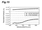
Fig. 15 . - As shown in
Fig. 15 , the absorber glass before heat treatment had a transmittance of approximately 10% or more in a wavelength range of approximately 600nm to approximately 980nm, whereas the absorber glass after heat treatment had a transmittance of 1×10⁻³% or less in a wavelength range of approximately 600nm to approximately 980nm, and particularly in a range of approximately 600nm to approximately 750nm, a very low transmittance of approximately 1×10⁻⁵ to approximately 1×10⁻⁶%. Thereby, it has been confirmed that the transmittance of the absorber glass after heat treatment is considerably reduced from the transmittance of the absorber glass before heat treatment. - It has been confirmed by the above that the absorption capacity is greatly improved, as a result of Fe3O4 being crystallized and precipitated on the absorber glass by heat treatment. Moreover, it has been confirmed that the absorption capacity is greatly improved, because the total surface area has been increased at an identical mass as a result of Fe3O4 being iron oxide crystals being particulated.
- Next, the inventors of the present invention prepared absorber glasses modified in the content of the iron oxide.
Fig. 16 shows, in terms of the samples of Nos. 1 to 13 of those prepared absorber glasses applied with a one-hour heat treatment at 750°C after cooling, a percentage by mass of the composition of each glass (numerical value after preparation of each absorber glass), a coefficient of thermal expansion, a glass transition point, a deformation point, a vitrified state, and a transmittance with respect to light having a wavelength of 850nm. The sample of No. 5 has the same composition as that of the absorber glass for which a structural analysis and a spectral transmittance measurement have been conducted before and after heat treatment. Moreover, samples No. 1 and No. 3 substantially not containing Fe3O4 were prepared as comparative examples with absorber glasses containing Fe3O4. Moreover, the transmittances of these absorber glasses were measured with the sample lap-polished to a thickness of 100µm and the wavelength fixed at 850nm by the aforementioned spectral transmittance measurement system. In sample No. 2 ofFig. 16 , a residual composition not displayed is ZnO: 4.5% and La2O3: 4.5% in percent by mass. - First, the transmittances of the absorber glasses where the iron oxide has become Fe3O4 and the transmittances of the absorber glasses where the iron oxide remains Fe2O3 and has not been crystallized were compared. As shown in No. 1 and No. 3, the absorber glasses where the iron oxide remains Fe2O3 have transmittances of approximately 10% to 20% with respect to an incident light having a wavelength of 850nm, whereas the absorber glasses where the iron oxide has become Fe3O4 shown in No. 2 and Nos. 4 to 13 have transmittances of approximately 1×10⁻⁵% to approximately 1×10⁻⁶% with respect to an incident light having a wavelength of 850nm. Thereby, it has been confirmed that the absorber glasses where the iron oxide has become Fe3O4 have considerably lower transmittances than those of the absorber glasses where the iron oxide remains Fe2O3.
- Next, vitrified states of the absorber glasses were confirmed focusing on the content of Fe3O4 of iron oxide crystals. It has been confirmed that the vitrified state is satisfactory in terms of the samples of Nos. 1 to 12, that is, the samples where the contents of Fe3O4 are 18.2 to 25% in percent by mass. However, in the sample of No. 13, that is, the sample where the content of Fe3O4 of iron oxide crystals is 30% in percent by mass, the vitrified state is insufficient as compared with that of the samples of Nos. 1 to 12. Therefore, vitrification can be sufficiently performed in a range where the content of Fe3O4 of iron oxide crystals is less than 30% in percent by mass.
- Next, conditions for precipitation of crystals of an iron oxide in a glass were studied. Processes of crystal nucleation and crystal growth are necessary for precipitating crystals in a glass. For the crystal nucleation, a crystal nucleator is used in most cases. When the crystal nucleator is added to the glass and a heat treatment is performed, a large number of micro crystallites containing a crystal nucleation component precipitate, and main crystals grow around those micro crystallites. Moreover, the rate of such crystal nucleation and crystal growth is in a relation of inverse proportion to the glass viscosity. Therefore, glass with a lower viscosity facilitates atomic movement, thereby promoting the crystal nucleation and crystal growth. The deformation temperature (At) provides an indication of the glass viscosity. Further, it is necessary that a sufficient amount of material to be crystallized is contained in the glass.
- When sorting out the conditions of a glass where crystals are likely to precipitate in line with the present example, there are conditions that: (1) Al2O3 has been added as a crystal nucleator and the moving distance of atoms is short, (2) the deformation temperature is low, and (3) the content of the iron oxide is above a certain level. Based on the above conditions, it has been confirmed in terms of the samples having large transmittances if these satisfy the satisfactory crystal precipitating conditions. First, in the sample of No. 1, the iron oxide content indicates a low value of 18.2% in percent by mass, and it has thus been confirmed that the material to be crystallized has not been sufficiently contained, and crystallization is unlikely to occur. Moreover, in the sample of No. 3, it has been confirmed that crystallization is unlikely to occur because the SiO2 content is large and the viscosity is slightly high, and atomic movement has not been sufficiently performed with the heat treatment condition of one hour at 750°C. Also, in the sample of No. 4 where Fe3O4 has been confirmed, it has been confirmed that crystallization does not sufficiently occur because the iron oxide content is not sufficient and the viscosity is also high. As described above, because sufficient crystallization has not occurred, the sample of No. 4 resulted in a larger transmittance than that of the samples of No. 2 and Nos. 5 to 13 where Fe3O4 has been crystallized. On the other hand, as shown by the samples of No. 2 and Nos. 5 to 13, it has been confirmed that satisfactory crystal precipitation occurs and the absorption capacity is improved in the absorber glasses where Al2O3 has been added as a crystal nucleator, the deformation temperature is low, and the content of the iron oxide is above a certain level.
- Next, a performance evaluation of the absorber glasses was performed. An FO is structured so that light in the air is gradually inhibited from being made incident into the FO as the center axes of the single fibers being components and the incident surface are slanted. By making in this state light incident into the incident surface of the FO from every direction and measuring the amount of light transmitted from the exit surface side of the FO, a performance evaluation of the absorber glasses can be performed. The smaller the amount of transmitted light, the more excellent the performance is.
- First, slant FOs were prepared using the absorber glasses shown in No. 4 and No. 8. These absorber glasses contain Fe3O4 being iron oxide crystals, and Fe3O4 contained in the absorber glass of No. 8 has been crystallized more than that in No. 4 as mentioned above. Moreover, a slant FO was prepared using the absorber glass containing Fe2O3 shown in No. 3 as a comparative example. The content of Fe2O3 shown in No. 3 is the same as the content of Fe3O4 shown in
Fig. 4 , which is favorable in comparing the absorption capacity resulting from the composition. Moreover, the glass compositions, the refractive indices, the coefficients of thermal expansion, the glass transition points, the deformation points, and the densities of a core glass and a cladding glass used in the present example are shown inFig. 17 . In addition, it suffices that the core glass is higher in refractive index than the cladding glass, and two composition examples of the core glass indicated in percentage by mass are shown in the present example. In a slant FO to be used for fingerprint detection, it is preferable to set the numerical aperture to 0.35 to 0.45 from the standpoint of resolution. - The transmittance of the prepared slant FOs was evaluated by the following procedure. As shown in
Fig. 18 , an LED light L having a wavelength of 850nm was made incident through adiffuser 40 made of opal glass into aslant FO 42 that has been lap-polished to a thickness of 1mm, and transmitted light was detected by asilicon photodiode 44. The measurement results are shown inFig. 19 . The transmittances shown inFig. 19 have been normalized with the transmittance at aslant angle 40° when the absorber glass shown by No. 8 ofFig. 16 was used, as 100. - First, it has been confirmed by a comparison between the transmittance of the absorber glass containing Fe2O3 shown in No. 3 of
Fig. 16 and the transmittance of the absorber glass containing Fe3O4 being iron oxide crystals shown in No. 4 that the transmittance of the absorber glass shown in No. 4 is smaller. Moreover, it has been confirmed by a comparison between the transmittance of the absorber glass shown in No. 8 and the transmittance of the absorber glass shown in No. 4 that the transmittance of the absorber glass shown in No. 8 where Fe3O4 has been crystallized more is smaller, and the absorber glass shown in No. 8 is more excellent in absorption capacity. - In the present example, the light L is diffused by the
diffuser 40 into various directions and made incident into theslant FO 42, and the incident light within the maximum light receiving angle results in an output of a total amount of light transmitted in the fibers and light reaching across the FO when the slant angle is large (here, 40°), and results in an output of only the amount of light reaching across the FO when the slant angle is small (here, 32° to 36°). That is, it has been indicated that, of the light made incident into theslant FO 42, light over the maximum light receiving angle (stray light) to be emitted across the FO can be shielded by adopting an absorber glass precipitated with crystals of Fe3O4. Accordingly, degradation in resolution and the like can be favorably prevented. - The embodiments described above indicate examples of an FO according to the present invention. The FO according to the present invention is not limited to these FOs according to the embodiments, and the FOs according to the embodiments may be modified, or applied to others, within a range not changing the gist described in the claims.
- The same effects as those of the present embodiment can also be obtained when, for example, FOs or slant FOs are joined by an adhesive and used. Moreover, the single fiber used in the present invention is not limited to the shape indicated in the present embodiment, and the same effects can be obtained even in, for example, a tapered form.
Claims (9)
- A fiber optic comprising:a plurality of fibers each including a core made of core glass for propagating light and a cladding for covering an outer periphery of the core and made of cladding glass lower in refractive index than the core glass; andan absorber glass arranged between the plurality of fibers and for absorbing light leaking from the plurality of fibers, whereinthe plurality of fibers are bundled and integrated, andthe absorber glass contains Fe3O4 being iron oxide crystals.
- The fiber optic according to claim 1, wherein the absorber glass is arranged between the plurality of fibers and covers outer peripheries of the plurality of fibers.
- The fiber optic according to claim 1, comprising a plurality of absorber glasses, wherein the cladding is arranged between the plurality of absorber glasses and covers outer peripheries of the plurality of absorber glasses.
- The fiber optic according to any one of claims 1 to 3, wherein the absorber glass contains Fe3O4 being iron oxide crystals of more than 18% and less than 30% in percent by mass.
- The fiber optic according to any one of claims 1 to 4, wherein Fe3O4 being iron oxide crystals of the absorber glass is granularly precipitated in the absorber glass.
- The fiber optic according to claim 5, wherein the absorber glass further contains Al2O3.
- The fiber optic according to claim 6, wherein the absorber glass contains Al2O3 of less than 7% in percent by mass.
- A fiber optic formed by drawing while heat-fusing a plurality of single fibers and a plurality of absorber glasses, the plurality of single fibers comprising core glass covered with cladding glass, the plurality of absorber glasses containing Fe3O4 being iron oxide crystals precipitated through a heat treatment.
- A fiber optic formed by drawing while heat-fusing a plurality of single fibers and a plurality of first absorber glasses, the plurality of single fibers comprising core glass covered with cladding glass, the plurality of first absorber glasses containing Fe2O3, wherein
a plurality of second absorber glasses formed of the plurality of first absorber glasses contain Fe3O4 being iron oxide crystals precipitated by heat at the time of heat fusing.
Applications Claiming Priority (2)
| Application Number | Priority Date | Filing Date | Title |
|---|---|---|---|
| JP2007032422A JP5259096B2 (en) | 2007-02-13 | 2007-02-13 | Fiber optic and manufacturing method thereof |
| PCT/JP2008/052053 WO2008099755A1 (en) | 2007-02-13 | 2008-02-07 | Fiber optic |
Publications (3)
| Publication Number | Publication Date |
|---|---|
| EP2110693A1 true EP2110693A1 (en) | 2009-10-21 |
| EP2110693A4 EP2110693A4 (en) | 2011-07-20 |
| EP2110693B1 EP2110693B1 (en) | 2013-05-22 |
Family
ID=39689991
Family Applications (1)
| Application Number | Title | Priority Date | Filing Date |
|---|---|---|---|
| EP08710932.8A Active EP2110693B1 (en) | 2007-02-13 | 2008-02-07 | Fiber optic |
Country Status (5)
| Country | Link |
|---|---|
| US (1) | US8116606B2 (en) |
| EP (1) | EP2110693B1 (en) |
| JP (1) | JP5259096B2 (en) |
| KR (1) | KR101514086B1 (en) |
| WO (1) | WO2008099755A1 (en) |
Cited By (1)
| Publication number | Priority date | Publication date | Assignee | Title |
|---|---|---|---|---|
| WO2015151074A1 (en) * | 2014-04-04 | 2015-10-08 | MAGNETI MARELLI S.p.A. | Led indicating device, in particular for a vehicle instrument cluster |
Families Citing this family (11)
| Publication number | Priority date | Publication date | Assignee | Title |
|---|---|---|---|---|
| JP5259096B2 (en) * | 2007-02-13 | 2013-08-07 | 浜松ホトニクス株式会社 | Fiber optic and manufacturing method thereof |
| US8335419B2 (en) * | 2008-11-10 | 2012-12-18 | Schott Corporation | Optical components with variable electro-chromic extra-mural absorption capability |
| JP5171569B2 (en) * | 2008-11-19 | 2013-03-27 | 浜松ホトニクス株式会社 | Fiber optic plate and manufacturing method thereof |
| US8558207B2 (en) * | 2009-09-29 | 2013-10-15 | Carestream Health, Inc. | Photostimulable plate reading device |
| CN101833147B (en) * | 2010-05-20 | 2014-05-07 | 潮州三环(集团)股份有限公司 | Multicore fiber inserting core body for gas tightness packaging of photoswitch |
| US9207398B2 (en) * | 2012-06-28 | 2015-12-08 | The United States Of America, As Represented By The Secretary Of The Navy | Multi-core optical fibers for IR image transmission |
| CN105372755B (en) * | 2015-11-24 | 2018-07-03 | 中国建筑材料科学研究总院 | Fibre faceplate and preparation method thereof |
| TWM570473U (en) | 2018-07-03 | 2018-11-21 | 金佶科技股份有限公司 | Image capturing module |
| US20220340480A1 (en) * | 2019-09-30 | 2022-10-27 | Hamamatsu Photonics K.K. | Fiber optics plate, scintillator panel, radiation detector, electron microscope, x-ray blocking method and electron beam blocking method |
| CN113603366B (en) * | 2021-09-14 | 2022-10-21 | 中国建筑材料科学研究总院有限公司 | Medium-expansion optical fiber image transmission element and preparation method thereof |
| US11931977B2 (en) * | 2022-03-31 | 2024-03-19 | Microsoft Technology Licensing, Llc | Multi-core polymer optical fibre and the fabrication thereof |
Citations (3)
| Publication number | Priority date | Publication date | Assignee | Title |
|---|---|---|---|---|
| US3901718A (en) * | 1969-01-03 | 1975-08-26 | American Optical Corp | Absorptive glass |
| US5815625A (en) * | 1995-07-04 | 1998-09-29 | Hamamatsu Photonics K.K. | Glass and fiber optic plate using the same |
| US6727198B1 (en) * | 1998-06-24 | 2004-04-27 | Nippon Electric Glass Co., Ltd. | Infrared absorbing glass for reed switch |
Family Cites Families (15)
| Publication number | Priority date | Publication date | Assignee | Title |
|---|---|---|---|---|
| WO1985002265A1 (en) * | 1983-11-07 | 1985-05-23 | The Dow Chemical Company | Low density, electromagnetic radiation absorption composition |
| JPH0238343A (en) | 1988-07-27 | 1990-02-07 | Nippon Electric Glass Co Ltd | Absorber glass for fiber plate |
| JPH0446786A (en) | 1990-06-12 | 1992-02-17 | Canon Inc | Method and device for disconnecting hand of robot |
| US5413971A (en) * | 1993-09-14 | 1995-05-09 | Mcpherson; Donald M. | Laser absorbing filter glass |
| JPH07325212A (en) | 1994-05-31 | 1995-12-12 | Daiichi Meteko Kk | Production of light-absorbing/radiating film and light-absorbing/radiating body |
| JP4046786B2 (en) * | 1995-07-04 | 2008-02-13 | 浜松ホトニクス株式会社 | Fiber optic plate |
| JP2001033635A (en) * | 1999-07-21 | 2001-02-09 | Hamamatsu Photonics Kk | Optical component and image picking-up device using it |
| WO2001069734A1 (en) * | 2000-03-10 | 2001-09-20 | Corning Incorporated | Optical fiber with absorbing overclad glass layer |
| EP1427677A2 (en) * | 2001-09-10 | 2004-06-16 | Schott Glas | Glass fibre with at least two glass layers |
| JP4060568B2 (en) | 2001-10-29 | 2008-03-12 | 浜松ホトニクス株式会社 | Absorber glass and fiber optic plate |
| JP4004351B2 (en) | 2002-08-16 | 2007-11-07 | 旭化成ホームズ株式会社 | Panel fixing bracket |
| US7641730B2 (en) * | 2003-02-27 | 2010-01-05 | Nippon Sheet Glass Company, Limited | Glass flake and method of manufacrturing the same |
| US20070196671A1 (en) * | 2004-03-30 | 2007-08-23 | Geltec Co., Ltd. | Electromagnetic wave absorber |
| JP2008184355A (en) | 2007-01-30 | 2008-08-14 | Ohara Inc | Optical glass |
| JP5259096B2 (en) * | 2007-02-13 | 2013-08-07 | 浜松ホトニクス株式会社 | Fiber optic and manufacturing method thereof |
-
2007
- 2007-02-13 JP JP2007032422A patent/JP5259096B2/en active Active
-
2008
- 2008-02-07 WO PCT/JP2008/052053 patent/WO2008099755A1/en active Application Filing
- 2008-02-07 EP EP08710932.8A patent/EP2110693B1/en active Active
- 2008-02-07 US US12/524,977 patent/US8116606B2/en active Active
- 2008-02-07 KR KR1020097009358A patent/KR101514086B1/en active IP Right Grant
Patent Citations (3)
| Publication number | Priority date | Publication date | Assignee | Title |
|---|---|---|---|---|
| US3901718A (en) * | 1969-01-03 | 1975-08-26 | American Optical Corp | Absorptive glass |
| US5815625A (en) * | 1995-07-04 | 1998-09-29 | Hamamatsu Photonics K.K. | Glass and fiber optic plate using the same |
| US6727198B1 (en) * | 1998-06-24 | 2004-04-27 | Nippon Electric Glass Co., Ltd. | Infrared absorbing glass for reed switch |
Non-Patent Citations (2)
| Title |
|---|
| See also references of WO2008099755A1 * |
| ZHONGSHEN Z ET AL: "Mossbauer studies on iron in polybasic silicate glass", JOURNAL OF NON-CRYSTALLINE SOLIDS, NORTH-HOLLAND PHYSICS PUBLISHING. AMSTERDAM, NL, vol. 84, no. 1-3, 2 July 1986 (1986-07-02) , pages 34-44, XP024062387, ISSN: 0022-3093, DOI: DOI:10.1016/0022-3093(86)90760-X [retrieved on 1986-07-02] * |
Cited By (3)
| Publication number | Priority date | Publication date | Assignee | Title |
|---|---|---|---|---|
| WO2015151074A1 (en) * | 2014-04-04 | 2015-10-08 | MAGNETI MARELLI S.p.A. | Led indicating device, in particular for a vehicle instrument cluster |
| CN106458034A (en) * | 2014-04-04 | 2017-02-22 | 马涅蒂-马瑞利公司 | LED indicating device, in particular for vehicle instrument cluster |
| US10137780B2 (en) | 2014-04-04 | 2018-11-27 | MAGNETI MARELLI S.p.A. | LED indicating device, in particular for a vehicle instrument cluster |
Also Published As
| Publication number | Publication date |
|---|---|
| JP2008197377A (en) | 2008-08-28 |
| WO2008099755A1 (en) | 2008-08-21 |
| JP5259096B2 (en) | 2013-08-07 |
| KR20090110820A (en) | 2009-10-22 |
| EP2110693A4 (en) | 2011-07-20 |
| EP2110693B1 (en) | 2013-05-22 |
| KR101514086B1 (en) | 2015-04-21 |
| US20100104248A1 (en) | 2010-04-29 |
| US8116606B2 (en) | 2012-02-14 |
Similar Documents
| Publication | Publication Date | Title |
|---|---|---|
| EP2110693B1 (en) | Fiber optic | |
| CN108139536B (en) | Image-conducting optical fiber | |
| CN111393023B (en) | High-definition optical fiber image inverter and preparation method and application thereof | |
| CN115368014B (en) | Light-absorbing frit glass for high-contrast optical fiber image inverter and preparation method thereof | |
| WO2023147756A1 (en) | Preparation method and use for φ40 mm large-size high-contrast optical fiber inverter | |
| CN116253507B (en) | High-refractive-index radiation-resistant glass material, and preparation method and application thereof | |
| CN106517772A (en) | Low-refractive glass applied to drawing formation preparation of optical fiber faceplate and preparation method thereof | |
| CN115536283B (en) | High refractive index fiber core glass for optical fiber image transmission element and preparation method thereof | |
| CN115469395A (en) | High-uniformity optical fiber image inverter and preparation method thereof | |
| EP0927705B1 (en) | Fiber optic plate | |
| CN116553822A (en) | Low-refractive-index radiation-resistant glass material, and preparation method and application thereof | |
| CN115304284B (en) | Low-refractive-index cortical glass for optical fiber image transmission element and preparation method thereof | |
| Hongisto et al. | Characterization of biodegradable core–clad borosilicate glass fibers with round and rectangular cross‐section | |
| RU2383907C2 (en) | System of optical devices with optical fibre made through fusion | |
| CN115353284B (en) | High-contrast optical fiber image transmission element and preparation method thereof | |
| JP4114410B2 (en) | Optical amplification glass fiber | |
| JP4046786B2 (en) | Fiber optic plate | |
| JP7474268B2 (en) | Fiber optic plate, scintillator panel, radiation detector, electron microscope, X-ray shielding method, and electron beam shielding method | |
| JP4060568B2 (en) | Absorber glass and fiber optic plate | |
| Pan et al. | Design and fabrication of a fiber optic image inverter based on a new high numerical aperture fiber optic glasses system | |
| CN117623620A (en) | High-transmittance optical fiber image transmission element, and preparation method and application thereof | |
| JPS63246703A (en) | Multiple light transmission body made of quartz glass | |
| GB2624492A (en) | Preparation method and use for Ø40 mm large-size high-contrast optical fiber inverter | |
| Tsujikawa et al. | Optical properties of multicomponent oxide glasses and glass fibers | |
| Kociszewski et al. | Fiber optic image guide rods in ultrathin endoscopy: material problems |
Legal Events
| Date | Code | Title | Description |
|---|---|---|---|
| PUAI | Public reference made under article 153(3) epc to a published international application that has entered the european phase |
Free format text: ORIGINAL CODE: 0009012 |
|
| 17P | Request for examination filed |
Effective date: 20090813 |
|
| AK | Designated contracting states |
Kind code of ref document: A1 Designated state(s): AT BE BG CH CY CZ DE DK EE ES FI FR GB GR HR HU IE IS IT LI LT LU LV MC MT NL NO PL PT RO SE SI SK TR |
|
| DAX | Request for extension of the european patent (deleted) | ||
| A4 | Supplementary search report drawn up and despatched |
Effective date: 20110622 |
|
| 17Q | First examination report despatched |
Effective date: 20110713 |
|
| GRAP | Despatch of communication of intention to grant a patent |
Free format text: ORIGINAL CODE: EPIDOSNIGR1 |
|
| RIC1 | Information provided on ipc code assigned before grant |
Ipc: C03C 3/083 20060101ALN20121105BHEP Ipc: G02B 6/06 20060101AFI20121105BHEP Ipc: C03C 13/04 20060101ALN20121105BHEP Ipc: G02B 6/036 20060101ALN20121105BHEP Ipc: C03C 4/08 20060101ALN20121105BHEP Ipc: G02B 6/00 20060101ALN20121105BHEP |
|
| GRAS | Grant fee paid |
Free format text: ORIGINAL CODE: EPIDOSNIGR3 |
|
| GRAA | (expected) grant |
Free format text: ORIGINAL CODE: 0009210 |
|
| AK | Designated contracting states |
Kind code of ref document: B1 Designated state(s): AT BE BG CH CY CZ DE DK EE ES FI FR GB GR HR HU IE IS IT LI LT LU LV MC MT NL NO PL PT RO SE SI SK TR |
|
| REG | Reference to a national code |
Ref country code: GB Ref legal event code: FG4D |
|
| REG | Reference to a national code |
Ref country code: CH Ref legal event code: EP |
|
| REG | Reference to a national code |
Ref country code: AT Ref legal event code: REF Ref document number: 613511 Country of ref document: AT Kind code of ref document: T Effective date: 20130615 |
|
| REG | Reference to a national code |
Ref country code: IE Ref legal event code: FG4D |
|
| REG | Reference to a national code |
Ref country code: DE Ref legal event code: R096 Ref document number: 602008024754 Country of ref document: DE Effective date: 20130718 |
|
| REG | Reference to a national code |
Ref country code: AT Ref legal event code: MK05 Ref document number: 613511 Country of ref document: AT Kind code of ref document: T Effective date: 20130522 |
|
| REG | Reference to a national code |
Ref country code: LT Ref legal event code: MG4D |
|
| PG25 | Lapsed in a contracting state [announced via postgrant information from national office to epo] |
Ref country code: AT Free format text: LAPSE BECAUSE OF FAILURE TO SUBMIT A TRANSLATION OF THE DESCRIPTION OR TO PAY THE FEE WITHIN THE PRESCRIBED TIME-LIMIT Effective date: 20130522 Ref country code: SI Free format text: LAPSE BECAUSE OF FAILURE TO SUBMIT A TRANSLATION OF THE DESCRIPTION OR TO PAY THE FEE WITHIN THE PRESCRIBED TIME-LIMIT Effective date: 20130522 Ref country code: SE Free format text: LAPSE BECAUSE OF FAILURE TO SUBMIT A TRANSLATION OF THE DESCRIPTION OR TO PAY THE FEE WITHIN THE PRESCRIBED TIME-LIMIT Effective date: 20130522 Ref country code: IS Free format text: LAPSE BECAUSE OF FAILURE TO SUBMIT A TRANSLATION OF THE DESCRIPTION OR TO PAY THE FEE WITHIN THE PRESCRIBED TIME-LIMIT Effective date: 20130922 Ref country code: ES Free format text: LAPSE BECAUSE OF FAILURE TO SUBMIT A TRANSLATION OF THE DESCRIPTION OR TO PAY THE FEE WITHIN THE PRESCRIBED TIME-LIMIT Effective date: 20130902 Ref country code: PT Free format text: LAPSE BECAUSE OF FAILURE TO SUBMIT A TRANSLATION OF THE DESCRIPTION OR TO PAY THE FEE WITHIN THE PRESCRIBED TIME-LIMIT Effective date: 20130923 Ref country code: NO Free format text: LAPSE BECAUSE OF FAILURE TO SUBMIT A TRANSLATION OF THE DESCRIPTION OR TO PAY THE FEE WITHIN THE PRESCRIBED TIME-LIMIT Effective date: 20130822 Ref country code: GR Free format text: LAPSE BECAUSE OF FAILURE TO SUBMIT A TRANSLATION OF THE DESCRIPTION OR TO PAY THE FEE WITHIN THE PRESCRIBED TIME-LIMIT Effective date: 20130823 Ref country code: LT Free format text: LAPSE BECAUSE OF FAILURE TO SUBMIT A TRANSLATION OF THE DESCRIPTION OR TO PAY THE FEE WITHIN THE PRESCRIBED TIME-LIMIT Effective date: 20130522 Ref country code: FI Free format text: LAPSE BECAUSE OF FAILURE TO SUBMIT A TRANSLATION OF THE DESCRIPTION OR TO PAY THE FEE WITHIN THE PRESCRIBED TIME-LIMIT Effective date: 20130522 |
|
| REG | Reference to a national code |
Ref country code: NL Ref legal event code: VDEP Effective date: 20130522 |
|
| PG25 | Lapsed in a contracting state [announced via postgrant information from national office to epo] |
Ref country code: HR Free format text: LAPSE BECAUSE OF FAILURE TO SUBMIT A TRANSLATION OF THE DESCRIPTION OR TO PAY THE FEE WITHIN THE PRESCRIBED TIME-LIMIT Effective date: 20130522 Ref country code: PL Free format text: LAPSE BECAUSE OF FAILURE TO SUBMIT A TRANSLATION OF THE DESCRIPTION OR TO PAY THE FEE WITHIN THE PRESCRIBED TIME-LIMIT Effective date: 20130522 Ref country code: BG Free format text: LAPSE BECAUSE OF FAILURE TO SUBMIT A TRANSLATION OF THE DESCRIPTION OR TO PAY THE FEE WITHIN THE PRESCRIBED TIME-LIMIT Effective date: 20130822 |
|
| PG25 | Lapsed in a contracting state [announced via postgrant information from national office to epo] |
Ref country code: LV Free format text: LAPSE BECAUSE OF FAILURE TO SUBMIT A TRANSLATION OF THE DESCRIPTION OR TO PAY THE FEE WITHIN THE PRESCRIBED TIME-LIMIT Effective date: 20130522 |
|
| PG25 | Lapsed in a contracting state [announced via postgrant information from national office to epo] |
Ref country code: SK Free format text: LAPSE BECAUSE OF FAILURE TO SUBMIT A TRANSLATION OF THE DESCRIPTION OR TO PAY THE FEE WITHIN THE PRESCRIBED TIME-LIMIT Effective date: 20130522 Ref country code: CZ Free format text: LAPSE BECAUSE OF FAILURE TO SUBMIT A TRANSLATION OF THE DESCRIPTION OR TO PAY THE FEE WITHIN THE PRESCRIBED TIME-LIMIT Effective date: 20130522 Ref country code: EE Free format text: LAPSE BECAUSE OF FAILURE TO SUBMIT A TRANSLATION OF THE DESCRIPTION OR TO PAY THE FEE WITHIN THE PRESCRIBED TIME-LIMIT Effective date: 20130522 Ref country code: DK Free format text: LAPSE BECAUSE OF FAILURE TO SUBMIT A TRANSLATION OF THE DESCRIPTION OR TO PAY THE FEE WITHIN THE PRESCRIBED TIME-LIMIT Effective date: 20130522 Ref country code: BE Free format text: LAPSE BECAUSE OF FAILURE TO SUBMIT A TRANSLATION OF THE DESCRIPTION OR TO PAY THE FEE WITHIN THE PRESCRIBED TIME-LIMIT Effective date: 20130522 |
|
| PG25 | Lapsed in a contracting state [announced via postgrant information from national office to epo] |
Ref country code: IT Free format text: LAPSE BECAUSE OF FAILURE TO SUBMIT A TRANSLATION OF THE DESCRIPTION OR TO PAY THE FEE WITHIN THE PRESCRIBED TIME-LIMIT Effective date: 20130522 Ref country code: RO Free format text: LAPSE BECAUSE OF FAILURE TO SUBMIT A TRANSLATION OF THE DESCRIPTION OR TO PAY THE FEE WITHIN THE PRESCRIBED TIME-LIMIT Effective date: 20130522 Ref country code: NL Free format text: LAPSE BECAUSE OF FAILURE TO SUBMIT A TRANSLATION OF THE DESCRIPTION OR TO PAY THE FEE WITHIN THE PRESCRIBED TIME-LIMIT Effective date: 20130522 |
|
| PLBE | No opposition filed within time limit |
Free format text: ORIGINAL CODE: 0009261 |
|
| STAA | Information on the status of an ep patent application or granted ep patent |
Free format text: STATUS: NO OPPOSITION FILED WITHIN TIME LIMIT |
|
| 26N | No opposition filed |
Effective date: 20140225 |
|
| REG | Reference to a national code |
Ref country code: DE Ref legal event code: R097 Ref document number: 602008024754 Country of ref document: DE Effective date: 20140225 |
|
| PG25 | Lapsed in a contracting state [announced via postgrant information from national office to epo] |
Ref country code: MC Free format text: LAPSE BECAUSE OF FAILURE TO SUBMIT A TRANSLATION OF THE DESCRIPTION OR TO PAY THE FEE WITHIN THE PRESCRIBED TIME-LIMIT Effective date: 20130522 Ref country code: LU Free format text: LAPSE BECAUSE OF FAILURE TO SUBMIT A TRANSLATION OF THE DESCRIPTION OR TO PAY THE FEE WITHIN THE PRESCRIBED TIME-LIMIT Effective date: 20140207 |
|
| REG | Reference to a national code |
Ref country code: CH Ref legal event code: PL |
|
| PG25 | Lapsed in a contracting state [announced via postgrant information from national office to epo] |
Ref country code: LI Free format text: LAPSE BECAUSE OF NON-PAYMENT OF DUE FEES Effective date: 20140228 Ref country code: CH Free format text: LAPSE BECAUSE OF NON-PAYMENT OF DUE FEES Effective date: 20140228 |
|
| REG | Reference to a national code |
Ref country code: IE Ref legal event code: MM4A |
|
| PG25 | Lapsed in a contracting state [announced via postgrant information from national office to epo] |
Ref country code: IE Free format text: LAPSE BECAUSE OF NON-PAYMENT OF DUE FEES Effective date: 20140207 |
|
| REG | Reference to a national code |
Ref country code: FR Ref legal event code: PLFP Year of fee payment: 9 |
|
| PG25 | Lapsed in a contracting state [announced via postgrant information from national office to epo] |
Ref country code: MT Free format text: LAPSE BECAUSE OF FAILURE TO SUBMIT A TRANSLATION OF THE DESCRIPTION OR TO PAY THE FEE WITHIN THE PRESCRIBED TIME-LIMIT Effective date: 20130522 |
|
| PG25 | Lapsed in a contracting state [announced via postgrant information from national office to epo] |
Ref country code: CY Free format text: LAPSE BECAUSE OF FAILURE TO SUBMIT A TRANSLATION OF THE DESCRIPTION OR TO PAY THE FEE WITHIN THE PRESCRIBED TIME-LIMIT Effective date: 20130522 |
|
| PG25 | Lapsed in a contracting state [announced via postgrant information from national office to epo] |
Ref country code: HU Free format text: LAPSE BECAUSE OF FAILURE TO SUBMIT A TRANSLATION OF THE DESCRIPTION OR TO PAY THE FEE WITHIN THE PRESCRIBED TIME-LIMIT; INVALID AB INITIO Effective date: 20080207 Ref country code: TR Free format text: LAPSE BECAUSE OF FAILURE TO SUBMIT A TRANSLATION OF THE DESCRIPTION OR TO PAY THE FEE WITHIN THE PRESCRIBED TIME-LIMIT Effective date: 20130522 |
|
| REG | Reference to a national code |
Ref country code: FR Ref legal event code: PLFP Year of fee payment: 10 |
|
| REG | Reference to a national code |
Ref country code: FR Ref legal event code: PLFP Year of fee payment: 11 |
|
| P01 | Opt-out of the competence of the unified patent court (upc) registered |
Effective date: 20230509 |
|
| PGFP | Annual fee paid to national office [announced via postgrant information from national office to epo] |
Ref country code: DE Payment date: 20231228 Year of fee payment: 17 Ref country code: GB Payment date: 20240108 Year of fee payment: 17 |
|
| PGFP | Annual fee paid to national office [announced via postgrant information from national office to epo] |
Ref country code: FR Payment date: 20240103 Year of fee payment: 17 |