EP2110523A1 - A device and method for active noise cancellation in an exhaust gas channel of a combustion engine - Google Patents
A device and method for active noise cancellation in an exhaust gas channel of a combustion engine Download PDFInfo
- Publication number
- EP2110523A1 EP2110523A1 EP08103557A EP08103557A EP2110523A1 EP 2110523 A1 EP2110523 A1 EP 2110523A1 EP 08103557 A EP08103557 A EP 08103557A EP 08103557 A EP08103557 A EP 08103557A EP 2110523 A1 EP2110523 A1 EP 2110523A1
- Authority
- EP
- European Patent Office
- Prior art keywords
- exhaust gas
- gas channel
- signal
- frequency signal
- sound
- Prior art date
- Legal status (The legal status is an assumption and is not a legal conclusion. Google has not performed a legal analysis and makes no representation as to the accuracy of the status listed.)
- Withdrawn
Links
Images

Classifications
-
- F—MECHANICAL ENGINEERING; LIGHTING; HEATING; WEAPONS; BLASTING
- F01—MACHINES OR ENGINES IN GENERAL; ENGINE PLANTS IN GENERAL; STEAM ENGINES
- F01N—GAS-FLOW SILENCERS OR EXHAUST APPARATUS FOR MACHINES OR ENGINES IN GENERAL; GAS-FLOW SILENCERS OR EXHAUST APPARATUS FOR INTERNAL-COMBUSTION ENGINES
- F01N1/00—Silencing apparatus characterised by method of silencing
- F01N1/06—Silencing apparatus characterised by method of silencing by using interference effect
- F01N1/065—Silencing apparatus characterised by method of silencing by using interference effect by using an active noise source, e.g. speakers
Definitions
- the invention relates to the field of active noise cancellation in an exhaust gas channel of a combustion engine.
- the patent EP 0 840 285 already discusses a device for active noise cancellation, with means to receive a sound signal from the exhaust gas channel, means to generate an anti noise signal, which, when acoustically coupled to the sound from exhaust gas channel, the result will be cancellation of both signals, resulting in reduction in noise.
- the invention provides a device and a method to reduce the noise in the exhaust gas channel of a combustion engine, taking into account also the sound reflections caused by an obstacle located near the exhaust gas channel opening. This will result in comfort for the driver especially when the car is being parked and the exhaust gas channel may be near to a wall or near to another vehicle.
- the major frequency component of the noise in the exhaust gas channel is estimated based on the engine speed. This involves only a simple but efficient computation.
- control logic becomes simple and more efficient.
- the relationship between the anti noise signal and the distance between an obstacle and the exhaust gas channel is available as pre stored data record, simplifying the computations at run time.
- Fig. 1 shows an active noise cancellation device 10 connected to a combustion engine 100 and to an exhaust gas channel.
- the combustion engine 100 is connected to an exhaust gas channel 102, 106 and 110.
- the exhaust gas channel includes a central muffler 104 and rear muffler 108.
- the combustion engine is connected over line 112 to the signal generator 200.
- the output of signal generator 200 is connected to a digital filter 202.
- the digital filter 202 also receives inputs from the calculation means 212.
- An obstacle 300 near the exhaust gas channel 110 causes the sound 300 to reflect in the surroundings.
- the reflections are shown as 304.
- the distance 306 between the obstacle and the exhaust gas channel influences the sound reflections 304.
- the calculation means 212 refers to the pre stored data records 210 in order to control the filter 202.
- the output of the digital filter 202 is given to an amplifier 208.
- the amplifier output is given to the sound converter 114 which is in close contact with the exhaust gas channel.
- the exhaust gas channel has a sound sensor 116 placed in it, output of sound sensor 116 is connected to the calculation means 212.
- the combustion engine 100 mixes fuel and air in a cylinder, which is ignited, resulting in kinetic energy to move the vehicle.
- the residual from the combustion engine passes through the exhaust gas channel 102, 106 and 110.
- the exhaust gases cause noise in the exhaust gas channel.
- the mufflers 104 and 108 help in reducing the noise generated by the exhaust gases, but the additional noise reduction is done by the active noise cancellation device.
- the active noise cancellation device typically operates by creating an anti noise signal which has same frequency as noise signal, is equal in amplitude and opposite in phase with noise signal which needs to be reduced.
- the noise signal and the anti noise signal are acoustically combined, the two signals effectively cancel one another, significantly reducing the final sound, emitted into the surroundings of the exhaust gas channel.
- the sound signal generated to reduce the noise signal can be used to have a particular sound design in the surroundings.
- the invention suggests a device which will reduce the noise in the exhaust gas channel of the combustion engine also taking into account the reflections of the sound caused by an obstacle near the exhaust gas channel 110.
- the signal generator 200 receives the initial parameters like engine speed, engine load etc. from the combustion engine 100 over the connection 112.
- the major frequency component of the noise in the exhaust gas channel will be directly dependant on the engine speed.
- the noise in the exhaust gas channel is generated when the exhaust gases rush into the exhaust gas channel.
- the frequency of the exhaust gases rushing into exhaust gas channel is dependant on the revolutions of the crankshaft, number of cylinders and number of strokes used in the cylinders of the combustion engine.
- the major component of the noise in the exhaust gas channel consists of the base frequency which is a function of engine parameters as explained above. But the noise signal will also have noticeable energy in the harmonics of the base frequency.
- the amplitude of the noise signal is dependant on the load of the engine.
- the calculation means 212 computes the base frequency of the noise generated in the exhaust gas channel.
- the signal generator 200 generates the estimated base frequency and its harmonics and feeds them to the digital filter 202.
- the digital filter 202 is shown as a single block but may consist of plurality of filters to generate a set of frequencies.
- the parameters of the digital filter 202 are controlled by the calculation means 212 to generate the anti noise signal with appropriate amplitude and phase to reduce the noise in the exhaust gas channel.
- the output from the digital filter 202 is given to an amplifier 208.
- the output of the amplifier 208 is used to drive a sound converter 114 like loud speaker, which is placed in the exhaust gas channel.
- the outlet of the speaker enclosure and exhaust gas channel are positioned such that the acoustic coupling between the exhaust gas noise and anti noise signal, result in a significant reduction of the total exhaust noise level.
- the static part of the noise reduction is done by estimating the base frequency using the engine speed and engine load parameters. Any correction required for the static part of the noise reduction is available in the pre stored data records. These data records are stored during the application phase of the engine test, during which the engine is tested under different conditions and the needed parameters are stored in the data records. The base frequency and its harmonics are generated with appropriate amplitude and phase and through the filter, amplifier and sound converter, the anti noise signal is finally mixed with the noise in the exhaust gas channel to reduce the noise.
- the dynamic part of the noise reduction is done using the feedback loop from the sound sensor.
- the sound sensor 116 may be a microphone or any similar transducer.
- the sound sensor 116 produces an exhaust noise feedback signal which is transmitted back to the calculation means 212.
- the exhaust noise feedback signal represents residual error between the exhaust noise and the anti noise signal.
- the calculation means 212 and the signal generator 200 will use the feedback signal along with the pre stored data records to fine tune the parameters of the digital filter 202 so that the resulting sound in the exhaust gas channel is at minimum level for the given conditions or for sound design.
- the active noise cancellation explained above is a typical concept used in an automobile.
- the invention extends this concept further to handle sound reflections 304 caused by an obstacle 300 near the exhaust gas channel 110.
- the obstacle 300 may be a wall or another vehicle, typically encountered during parking of a vehicle.
- the obstacle 300 near the exhaust gas channel 110 causes in the sound sensor 116 an overlay of sound signals from the final muffler 108 and reflected sound 304. This will result in resonances and also amplification of some selected frequencies.
- the influencing of the acoustic behaviour of the active noise cancellation device by the reflected sound 304 can lead to unwanted behaviour of the device, e.g., to an unstable behaviour with the production of disturbing sound signals.
- the correction depends upon the distance 306 between the obstacle 300 and the exhaust gas channel 110.
- the distance 306 is measured by a distance measuring device which is not shown in the figure and which is external to the active noise cancellation device.
- Distance measuring devices at the rear of the vehicle are a state of the art. These distance measuring devices use a transmitter and a receiver. The transmitter transmits a signal and the receiver receives the signal reflected by an obstacle. The time difference between transmission and reception of the signal is processed and the distance between the transmitter and the obstacle is computed. The distance measuring devices in the vehicles do the distance measurements in real time and inform the user through audio or visual indicators about the obstacles near the rear of the vehicle. This information will be useful especially during parking of the vehicle.
- Different distance measuring devices may use different techniques for measurements like ultrasonic sensors, radar sensors or lasers etc.
- the invention proposes that the active noise cancellation device 10 receives one or more distance values 308 from the distance measuring device.
- the calculation means receives the distance values 308.
- the anti noise signal is either made in-active or a suitable correction is applied to the anti noise signal which is used to influence the noise in the exhaust gas channel.
- the correction values are determined for different distance values 308 during the application phase of the engine and stored as part of the pre-stored data records 210.
- test engine For the determination of pre-stored data, a test engine of type of the later engine is used. Beside fabrication tolerances, test engine will have similar characteristics as that of the actual engine in the vehicle.
- the active noise cancellation device 10 is housed in a casing with input connection 112 for connection with engine, input connection 214 from sound sensor, input connection 308 for connection with a distance measuring device, an output connection 209 for sound converter and other required wiring for power supply.
- the digital filter is shown in the figure 1 as separate element as an example. But the digital filter can also be built into the signal generator.
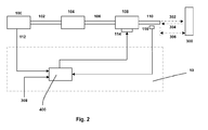
- Figure 2 shows another embodiment of the invention.
- 100, 102, 104, 106, 108, 110, 112 and 114 are same elements as shown in figure 1 and have the same functionality.
- the electronic device used for active noise cancellation is integrated into the existing engine control unit 400.
- the electronic control unit 400 does the complete control and monitoring of the vehicle engine.
- the functionality of active noise cancellation is made part of the engine control unit 400 by integrating the signal generator, filters, amplifier, calculation means and data records as a single unit.
Landscapes
- Engineering & Computer Science (AREA)
- Chemical & Material Sciences (AREA)
- Combustion & Propulsion (AREA)
- Mechanical Engineering (AREA)
- General Engineering & Computer Science (AREA)
- Exhaust Silencers (AREA)
- Soundproofing, Sound Blocking, And Sound Damping (AREA)
Abstract
Description
- The invention relates to the field of active noise cancellation in an exhaust gas channel of a combustion engine. The patent
EP 0 840 285 already discusses a device for active noise cancellation, with means to receive a sound signal from the exhaust gas channel, means to generate an anti noise signal, which, when acoustically coupled to the sound from exhaust gas channel, the result will be cancellation of both signals, resulting in reduction in noise. - The invention with the features of the independent claims has the following advantages:
- The invention provides a device and a method to reduce the noise in the exhaust gas channel of a combustion engine, taking into account also the sound reflections caused by an obstacle located near the exhaust gas channel opening. This will result in comfort for the driver especially when the car is being parked and the exhaust gas channel may be near to a wall or near to another vehicle.
- Further improvements and/or advantages are realised by the features of the dependent patent claims.
- The major frequency component of the noise in the exhaust gas channel is estimated based on the engine speed. This involves only a simple but efficient computation.
- As the pre stored data records are used to compute the dynamic part of the noise compensation, the control logic becomes simple and more efficient.
- The relationship between the anti noise signal and the distance between an obstacle and the exhaust gas channel is available as pre stored data record, simplifying the computations at run time.
- Also as the pre stored data records are created off line during application phase of the engine, large and accurate data can be stored.
-
- Fig. 1
- shows the invention according to a first embodiment
- Fig. 2
- shows the invention according to a first embodiment
-
Fig. 1 shows an activenoise cancellation device 10 connected to acombustion engine 100 and to an exhaust gas channel. Thecombustion engine 100 is connected to anexhaust gas channel central muffler 104 andrear muffler 108. The combustion engine is connected overline 112 to thesignal generator 200. The output ofsignal generator 200 is connected to adigital filter 202. Thedigital filter 202 also receives inputs from the calculation means 212. - An
obstacle 300 near theexhaust gas channel 110 causes thesound 300 to reflect in the surroundings. The reflections are shown as 304. - The
distance 306 between the obstacle and the exhaust gas channel, influences thesound reflections 304. A device which is not shown in the figure and which is external to the active noise control device, measures thedistance 306 between theobstacle 300 and theexhaust gas channel 110. Thisdistance 306 is delivered to the calculation means 212 as adistance value 308. - The calculation means 212 refers to the pre stored
data records 210 in order to control thefilter 202. The output of thedigital filter 202 is given to anamplifier 208. The amplifier output is given to thesound converter 114 which is in close contact with the exhaust gas channel. The exhaust gas channel has asound sensor 116 placed in it, output ofsound sensor 116 is connected to the calculation means 212. - The
combustion engine 100 mixes fuel and air in a cylinder, which is ignited, resulting in kinetic energy to move the vehicle. The residual from the combustion engine passes through theexhaust gas channel mufflers - The active noise cancellation device typically operates by creating an anti noise signal which has same frequency as noise signal, is equal in amplitude and opposite in phase with noise signal which needs to be reduced. When the noise signal and the anti noise signal are acoustically combined, the two signals effectively cancel one another, significantly reducing the final sound, emitted into the surroundings of the exhaust gas channel.
- Also the sound signal generated to reduce the noise signal, can be used to have a particular sound design in the surroundings.
- The invention suggests a device which will reduce the noise in the exhaust gas channel of the combustion engine also taking into account the reflections of the sound caused by an obstacle near the
exhaust gas channel 110. - In
Fig. 1 , thesignal generator 200 receives the initial parameters like engine speed, engine load etc. from thecombustion engine 100 over theconnection 112. The major frequency component of the noise in the exhaust gas channel will be directly dependant on the engine speed. The noise in the exhaust gas channel is generated when the exhaust gases rush into the exhaust gas channel. The frequency of the exhaust gases rushing into exhaust gas channel is dependant on the revolutions of the crankshaft, number of cylinders and number of strokes used in the cylinders of the combustion engine. - The major component of the noise in the exhaust gas channel consists of the base frequency which is a function of engine parameters as explained above. But the noise signal will also have noticeable energy in the harmonics of the base frequency.
- The amplitude of the noise signal is dependant on the load of the engine. Based on the initial parameters, the calculation means 212 computes the base frequency of the noise generated in the exhaust gas channel. The
signal generator 200 generates the estimated base frequency and its harmonics and feeds them to thedigital filter 202. Thedigital filter 202 is shown as a single block but may consist of plurality of filters to generate a set of frequencies. The parameters of thedigital filter 202 are controlled by the calculation means 212 to generate the anti noise signal with appropriate amplitude and phase to reduce the noise in the exhaust gas channel. The output from thedigital filter 202 is given to anamplifier 208. The output of theamplifier 208 is used to drive asound converter 114 like loud speaker, which is placed in the exhaust gas channel. The outlet of the speaker enclosure and exhaust gas channel are positioned such that the acoustic coupling between the exhaust gas noise and anti noise signal, result in a significant reduction of the total exhaust noise level. - The static part of the noise reduction is done by estimating the base frequency using the engine speed and engine load parameters. Any correction required for the static part of the noise reduction is available in the pre stored data records. These data records are stored during the application phase of the engine test, during which the engine is tested under different conditions and the needed parameters are stored in the data records. The base frequency and its harmonics are generated with appropriate amplitude and phase and through the filter, amplifier and sound converter, the anti noise signal is finally mixed with the noise in the exhaust gas channel to reduce the noise.
- The dynamic part of the noise reduction is done using the feedback loop from the sound sensor.
- Any residual noise which remains in the
exhaust gas channel 110 is received by asound sensor 116. The sound sensor may be a microphone or any similar transducer. Thesound sensor 116 produces an exhaust noise feedback signal which is transmitted back to the calculation means 212. The exhaust noise feedback signal represents residual error between the exhaust noise and the anti noise signal. - The calculation means 212 and the
signal generator 200 will use the feedback signal along with the pre stored data records to fine tune the parameters of thedigital filter 202 so that the resulting sound in the exhaust gas channel is at minimum level for the given conditions or for sound design. - The active noise cancellation explained above is a typical concept used in an automobile. The invention extends this concept further to handle
sound reflections 304 caused by anobstacle 300 near theexhaust gas channel 110. Theobstacle 300 may be a wall or another vehicle, typically encountered during parking of a vehicle. Theobstacle 300 near theexhaust gas channel 110 causes in thesound sensor 116 an overlay of sound signals from thefinal muffler 108 and reflectedsound 304. This will result in resonances and also amplification of some selected frequencies. - The influencing of the acoustic behaviour of the active noise cancellation device by the reflected
sound 304 can lead to unwanted behaviour of the device, e.g., to an unstable behaviour with the production of disturbing sound signals. - To overcome this problem a correction needs to be applied for the anti noise signal generated to cancel the noise in the exhaust gas channel. The correction depends upon the
distance 306 between theobstacle 300 and theexhaust gas channel 110. Thedistance 306 is measured by a distance measuring device which is not shown in the figure and which is external to the active noise cancellation device. - Distance measuring devices at the rear of the vehicle, are a state of the art. These distance measuring devices use a transmitter and a receiver. The transmitter transmits a signal and the receiver receives the signal reflected by an obstacle. The time difference between transmission and reception of the signal is processed and the distance between the transmitter and the obstacle is computed. The distance measuring devices in the vehicles do the distance measurements in real time and inform the user through audio or visual indicators about the obstacles near the rear of the vehicle. This information will be useful especially during parking of the vehicle.
- Different distance measuring devices may use different techniques for measurements like ultrasonic sensors, radar sensors or lasers etc.
- The invention proposes that the active
noise cancellation device 10 receives one ormore distance values 308 from the distance measuring device. - The calculation means receives the distance values 308. As a function of the distance values 308 the anti noise signal is either made in-active or a suitable correction is applied to the anti noise signal which is used to influence the noise in the exhaust gas channel. The correction values are determined for
different distance values 308 during the application phase of the engine and stored as part of the pre-stored data records 210. - For the determination of pre-stored data, a test engine of type of the later engine is used. Beside fabrication tolerances, test engine will have similar characteristics as that of the actual engine in the vehicle.
- The active
noise cancellation device 10 is housed in a casing withinput connection 112 for connection with engine,input connection 214 from sound sensor,input connection 308 for connection with a distance measuring device, anoutput connection 209 for sound converter and other required wiring for power supply. - The digital filter is shown in the
figure 1 as separate element as an example. But the digital filter can also be built into the signal generator. -
Figure 2 shows another embodiment of the invention. Here 100, 102, 104, 106, 108, 110, 112 and 114 are same elements as shown infigure 1 and have the same functionality. The electronic device used for active noise cancellation is integrated into the existingengine control unit 400. - The
electronic control unit 400 does the complete control and monitoring of the vehicle engine. The functionality of active noise cancellation is made part of theengine control unit 400 by integrating the signal generator, filters, amplifier, calculation means and data records as a single unit.
Claims (9)
- A device for active noise cancellation in exhaust gas channel of a combustion engine, comprising,- means to receive a sound signal from exhaust gas channel- means to generate a frequency signal, to influence the sound generated in the exhaust gas channel,- calculation means receiving the sound signal and generating control signals to influence amplitude and phase of the frequency signal,characterised in that the said device also receives information about the distance of the exhaust gas channel from an obstacle and uses this information to modify the frequency signal.
- A device as claimed in claim 1 characterised in that the information about the distance of the exhaust gas channel from any obstacle, is provided by a device external to the active noise cancellation device.
- A device as claimed in claim 1 characterised in that the means to generate the frequency signal receives a speed signal of combustion engine and derives a first frequency signal dependant of the speed signal.
- A device as claimed in claim 1 characterised in that the means to generate the frequency signal, generates further frequencies which are harmonics of the first frequency.
- A device as claimed in claim 1 characterised in that the calculation means uses pre-stored data records giving dependency between engine speed, engine load and, phase and amplitude of the frequency signal.
- A device as claimed in claim 1 characterised in that the calculation means uses pre-stored data records giving dependency between the frequency signal and the distance of the exhaust gas channel from the obstacle.
- A device as claimed in claim 1 characterised in that the calculation means receives the feed back signal from the sound sensor and derives the control signals for the signal generator and filters.
- A device as claimed in claim 1 characterised in that the pre-stored data records are derived during the application phase under which the engine is tested under different conditions and the data records are stored.
- Method of operating an active noise cancellation characterised by the steps of- receiving a sound signal from an exhaust gas channel of the combustion engine through a sound sensor,- based on received sound signal, generating control signals for a signal generator and digital filters, to influence amplitude and phase of a frequency signal,- receiving information about the distance of the exhaust gas channel from any obstacle- suitably modifying the frequency signal using the pres-stored data records of the dependency between the frequency signal and the distance of exhaust gas channel from the obstacle- acoustically coupling the frequency signal with the sound generated in the exhaust gas channel using a sound converter, to influence the sound generated in the exhaust gas channel,
Priority Applications (3)
| Application Number | Priority Date | Filing Date | Title |
|---|---|---|---|
| EP08103557A EP2110523A1 (en) | 2008-04-16 | 2008-04-16 | A device and method for active noise cancellation in an exhaust gas channel of a combustion engine |
| JP2009094752A JP2009257326A (en) | 2008-04-16 | 2009-04-09 | Device and method for active noise cancellation in exhaust gas channel of internal combustion engine |
| US12/423,514 US8085944B2 (en) | 2008-04-16 | 2009-04-14 | Device and method for active noise cancellation in an exhaust gas channel of a combustion engine |
Applications Claiming Priority (1)
| Application Number | Priority Date | Filing Date | Title |
|---|---|---|---|
| EP08103557A EP2110523A1 (en) | 2008-04-16 | 2008-04-16 | A device and method for active noise cancellation in an exhaust gas channel of a combustion engine |
Publications (1)
| Publication Number | Publication Date |
|---|---|
| EP2110523A1 true EP2110523A1 (en) | 2009-10-21 |
Family
ID=39739771
Family Applications (1)
| Application Number | Title | Priority Date | Filing Date |
|---|---|---|---|
| EP08103557A Withdrawn EP2110523A1 (en) | 2008-04-16 | 2008-04-16 | A device and method for active noise cancellation in an exhaust gas channel of a combustion engine |
Country Status (3)
| Country | Link |
|---|---|
| US (1) | US8085944B2 (en) |
| EP (1) | EP2110523A1 (en) |
| JP (1) | JP2009257326A (en) |
Cited By (3)
| Publication number | Priority date | Publication date | Assignee | Title |
|---|---|---|---|---|
| US20110215796A1 (en) * | 2010-01-21 | 2011-09-08 | Commissariat A L'energie Atomique Et Aux Energies Alternatives | Measurement of a cyclic motion of a ferromagnetic part |
| DE102011009848A1 (en) | 2011-01-27 | 2012-08-02 | Iav Gmbh Ingenieurgesellschaft Auto Und Verkehr | Device for determining sound emission features of combustion engine mounted in vehicle, has emission source that transmits modulated ultrasonic signal from ultrasonic transmitter to ultrasonic receiver on transmission path to emit sound |
| GB2531637A (en) * | 2014-08-20 | 2016-04-27 | Jaguar Land Rover Ltd | Vehicle noise suppression method |
Families Citing this family (6)
| Publication number | Priority date | Publication date | Assignee | Title |
|---|---|---|---|---|
| DE102006059351A1 (en) * | 2006-12-15 | 2008-06-19 | Robert Bosch Gmbh | Method for influencing sound |
| JP2011191383A (en) | 2010-03-12 | 2011-09-29 | Panasonic Corp | Noise reduction device |
| DE102011116991B4 (en) * | 2011-10-26 | 2018-12-06 | Austriamicrosystems Ag | Noise suppression system and method for noise suppression |
| US9269344B2 (en) * | 2013-09-03 | 2016-02-23 | Bose Corporation | Engine harmonic cancellation system afterglow mitigation |
| EP3038102B1 (en) * | 2014-12-24 | 2019-07-24 | Magneti Marelli S.p.A. | Method for performing an active profiling of a sound emitted by an engine and corresponding profiling system |
| EP3610989A1 (en) | 2018-08-14 | 2020-02-19 | Hilti Aktiengesellschaft | Headset for active noise suppression, helmet comprising such a headset, system comprising such a headset and a hand-held machine tool |
Citations (5)
| Publication number | Priority date | Publication date | Assignee | Title |
|---|---|---|---|---|
| US5222148A (en) * | 1992-04-29 | 1993-06-22 | General Motors Corporation | Active noise control system for attenuating engine generated noise |
| EP0592693A1 (en) * | 1992-05-01 | 1994-04-20 | Fujitsu Ten, Ltd. | Noise control device |
| US5325438A (en) * | 1993-02-01 | 1994-06-28 | At&T Bell Laboratories | Active noise-cancellation system for automotive mufflers |
| US5692052A (en) * | 1991-06-17 | 1997-11-25 | Nippondenso Co., Ltd. | Engine noise control apparatus |
| EP0840285A2 (en) | 1996-11-04 | 1998-05-06 | Tenneco Automotive Inc. | Active noise conditioning system |
Family Cites Families (7)
| Publication number | Priority date | Publication date | Assignee | Title |
|---|---|---|---|---|
| US5410606A (en) * | 1992-07-21 | 1995-04-25 | Honda Giken Kogyo Kabushiki Kaisha | Noise canceling method |
| JP3506449B2 (en) * | 1992-12-04 | 2004-03-15 | 富士通テン株式会社 | Noise control device |
| JP3916266B2 (en) * | 1994-12-26 | 2007-05-16 | 富士通テン株式会社 | Noise control device |
| JPH09146559A (en) * | 1995-11-22 | 1997-06-06 | Fujitsu Ten Ltd | Noise control device |
| JPH09242628A (en) * | 1996-03-07 | 1997-09-16 | Unisia Jecs Corp | Active noise control system for automobile |
| JP2003241767A (en) * | 2002-02-14 | 2003-08-29 | Alpine Electronics Inc | Noise canceler |
| US20070297619A1 (en) * | 2006-06-26 | 2007-12-27 | Bose Corporation*Ewc* | Active noise reduction engine speed determining |
-
2008
- 2008-04-16 EP EP08103557A patent/EP2110523A1/en not_active Withdrawn
-
2009
- 2009-04-09 JP JP2009094752A patent/JP2009257326A/en active Pending
- 2009-04-14 US US12/423,514 patent/US8085944B2/en not_active Expired - Fee Related
Patent Citations (5)
| Publication number | Priority date | Publication date | Assignee | Title |
|---|---|---|---|---|
| US5692052A (en) * | 1991-06-17 | 1997-11-25 | Nippondenso Co., Ltd. | Engine noise control apparatus |
| US5222148A (en) * | 1992-04-29 | 1993-06-22 | General Motors Corporation | Active noise control system for attenuating engine generated noise |
| EP0592693A1 (en) * | 1992-05-01 | 1994-04-20 | Fujitsu Ten, Ltd. | Noise control device |
| US5325438A (en) * | 1993-02-01 | 1994-06-28 | At&T Bell Laboratories | Active noise-cancellation system for automotive mufflers |
| EP0840285A2 (en) | 1996-11-04 | 1998-05-06 | Tenneco Automotive Inc. | Active noise conditioning system |
Cited By (6)
| Publication number | Priority date | Publication date | Assignee | Title |
|---|---|---|---|---|
| US20110215796A1 (en) * | 2010-01-21 | 2011-09-08 | Commissariat A L'energie Atomique Et Aux Energies Alternatives | Measurement of a cyclic motion of a ferromagnetic part |
| US8773113B2 (en) * | 2010-01-21 | 2014-07-08 | Commissariat A L'energie Atomique Et Aux Energies Alternatives | Measurement of a cyclic motion of a ferromagnetic part |
| DE102011009848A1 (en) | 2011-01-27 | 2012-08-02 | Iav Gmbh Ingenieurgesellschaft Auto Und Verkehr | Device for determining sound emission features of combustion engine mounted in vehicle, has emission source that transmits modulated ultrasonic signal from ultrasonic transmitter to ultrasonic receiver on transmission path to emit sound |
| GB2531637A (en) * | 2014-08-20 | 2016-04-27 | Jaguar Land Rover Ltd | Vehicle noise suppression method |
| GB2531637B (en) * | 2014-08-20 | 2018-05-23 | Jaguar Land Rover Ltd | Vehicle noise suppression method |
| US10174653B2 (en) | 2014-08-20 | 2019-01-08 | Jaguar Land Rover Limited | Vehicle noise suppression method |
Also Published As
| Publication number | Publication date |
|---|---|
| JP2009257326A (en) | 2009-11-05 |
| US8085944B2 (en) | 2011-12-27 |
| US20090260916A1 (en) | 2009-10-22 |
Similar Documents
| Publication | Publication Date | Title |
|---|---|---|
| US8085944B2 (en) | Device and method for active noise cancellation in an exhaust gas channel of a combustion engine | |
| US7753165B2 (en) | Device and method for active noise cancellation in exhaust gas channel of a combustion engine | |
| EP2600342B1 (en) | Active design of exhaust sounds | |
| US8194873B2 (en) | Active noise reduction adaptive filter leakage adjusting | |
| US9729966B2 (en) | Active noise reduction engine speed determining | |
| US8204243B2 (en) | Synthetic engine sound for electric vehicle based on detected direction of travel | |
| US9084039B2 (en) | Overload protection for loudspeakers in exhaust systems | |
| US20090220102A1 (en) | Active Noise Reduction Adaptive Filter Leakage Adjusting | |
| US20140321659A1 (en) | System for influencing exhaust noise, engine noise and/or intake noise | |
| US6625284B1 (en) | Comfort noise generating apparatus | |
| CN108699934B (en) | Motor vehicle with control device for at least one loudspeaker for a motor vehicle exhaust system | |
| CN104067140A (en) | Environment detection device and related method for determining the position and/or motion of an object | |
| EP2072769B1 (en) | A device and method for active noise cancellation in exhaust gas channel of a combustion engine | |
| US20030112981A1 (en) | Active noise control with on-line-filtered C modeling | |
| JP2980007B2 (en) | Exhaust sound quality improvement device | |
| EP1154402A2 (en) | Active noise cancellation system | |
| US7437236B2 (en) | Method for customizing the properties of a drive assembly in motor vehicles | |
| JP2000020073A (en) | Muffler device | |
| JP3332162B2 (en) | Active silencer | |
| JPH07199964A (en) | Adaptive active silencer for vehicle interior sound | |
| RU2763309C1 (en) | Adaptive method for active noise damping in the car interior and a device for its implementation | |
| JP3395312B2 (en) | Adaptive active silencer for vehicle interior sound | |
| KR101816265B1 (en) | Apparatus for driving ultrasonic sensor and system driving ultrasonic sensor including the same and method for driving ultrasonic sensor | |
| JP2001182807A (en) | Gear noise reducing device for vehicular automatic transmission | |
| JPH07199967A (en) | Adaptive active silencer for vehicle interior sound |
Legal Events
| Date | Code | Title | Description |
|---|---|---|---|
| PUAI | Public reference made under article 153(3) epc to a published international application that has entered the european phase |
Free format text: ORIGINAL CODE: 0009012 |
|
| AK | Designated contracting states |
Kind code of ref document: A1 Designated state(s): AT BE BG CH CY CZ DE DK EE ES FI FR GB GR HR HU IE IS IT LI LT LU LV MC MT NL NO PL PT RO SE SI SK TR |
|
| AX | Request for extension of the european patent |
Extension state: AL BA MK RS |
|
| 17P | Request for examination filed |
Effective date: 20100421 |
|
| AKX | Designation fees paid |
Designated state(s): AT BE BG CH CY CZ DE DK EE ES FI FR GB GR HR HU IE IS IT LI LT LU LV MC MT NL NO PL PT RO SE SI SK TR |
|
| RTI1 | Title (correction) |
Free format text: DEVICE AND METHOD FOR ACTIVE NOISE CANCELATION IN AN EXHAUST GAS CHANNEL OF A COMBUSTION ENGINE |
|
| 17Q | First examination report despatched |
Effective date: 20120410 |
|
| STAA | Information on the status of an ep patent application or granted ep patent |
Free format text: STATUS: THE APPLICATION IS DEEMED TO BE WITHDRAWN |
|
| 18D | Application deemed to be withdrawn |
Effective date: 20141101 |