EP2110513A2 - Reduced weight blade for a gas turbine engine - Google Patents
Reduced weight blade for a gas turbine engine Download PDFInfo
- Publication number
- EP2110513A2 EP2110513A2 EP09250721A EP09250721A EP2110513A2 EP 2110513 A2 EP2110513 A2 EP 2110513A2 EP 09250721 A EP09250721 A EP 09250721A EP 09250721 A EP09250721 A EP 09250721A EP 2110513 A2 EP2110513 A2 EP 2110513A2
- Authority
- EP
- European Patent Office
- Prior art keywords
- aperture
- rotor blade
- section
- recited
- platform
- Prior art date
- Legal status (The legal status is an assumption and is not a legal conclusion. Google has not performed a legal analysis and makes no representation as to the accuracy of the status listed.)
- Withdrawn
Links
Images




Classifications
-
- F—MECHANICAL ENGINEERING; LIGHTING; HEATING; WEAPONS; BLASTING
- F01—MACHINES OR ENGINES IN GENERAL; ENGINE PLANTS IN GENERAL; STEAM ENGINES
- F01D—NON-POSITIVE DISPLACEMENT MACHINES OR ENGINES, e.g. STEAM TURBINES
- F01D5/00—Blades; Blade-carrying members; Heating, heat-insulating, cooling or antivibration means on the blades or the members
- F01D5/12—Blades
- F01D5/14—Form or construction
- F01D5/147—Construction, i.e. structural features, e.g. of weight-saving hollow blades
-
- F—MECHANICAL ENGINEERING; LIGHTING; HEATING; WEAPONS; BLASTING
- F01—MACHINES OR ENGINES IN GENERAL; ENGINE PLANTS IN GENERAL; STEAM ENGINES
- F01D—NON-POSITIVE DISPLACEMENT MACHINES OR ENGINES, e.g. STEAM TURBINES
- F01D5/00—Blades; Blade-carrying members; Heating, heat-insulating, cooling or antivibration means on the blades or the members
- F01D5/12—Blades
- F01D5/14—Form or construction
- F01D5/18—Hollow blades, i.e. blades with cooling or heating channels or cavities; Heating, heat-insulating or cooling means on blades
- F01D5/187—Convection cooling
-
- F—MECHANICAL ENGINEERING; LIGHTING; HEATING; WEAPONS; BLASTING
- F05—INDEXING SCHEMES RELATING TO ENGINES OR PUMPS IN VARIOUS SUBCLASSES OF CLASSES F01-F04
- F05D—INDEXING SCHEME FOR ASPECTS RELATING TO NON-POSITIVE-DISPLACEMENT MACHINES OR ENGINES, GAS-TURBINES OR JET-PROPULSION PLANTS
- F05D2220/00—Application
- F05D2220/30—Application in turbines
- F05D2220/32—Application in turbines in gas turbines
- F05D2220/321—Application in turbines in gas turbines for a special turbine stage
-
- F—MECHANICAL ENGINEERING; LIGHTING; HEATING; WEAPONS; BLASTING
- F05—INDEXING SCHEMES RELATING TO ENGINES OR PUMPS IN VARIOUS SUBCLASSES OF CLASSES F01-F04
- F05D—INDEXING SCHEME FOR ASPECTS RELATING TO NON-POSITIVE-DISPLACEMENT MACHINES OR ENGINES, GAS-TURBINES OR JET-PROPULSION PLANTS
- F05D2240/00—Components
- F05D2240/80—Platforms for stationary or moving blades
- F05D2240/81—Cooled platforms
-
- F—MECHANICAL ENGINEERING; LIGHTING; HEATING; WEAPONS; BLASTING
- F05—INDEXING SCHEMES RELATING TO ENGINES OR PUMPS IN VARIOUS SUBCLASSES OF CLASSES F01-F04
- F05D—INDEXING SCHEME FOR ASPECTS RELATING TO NON-POSITIVE-DISPLACEMENT MACHINES OR ENGINES, GAS-TURBINES OR JET-PROPULSION PLANTS
- F05D2250/00—Geometry
- F05D2250/20—Three-dimensional
- F05D2250/29—Three-dimensional machined; miscellaneous
- F05D2250/291—Three-dimensional machined; miscellaneous hollowed
-
- F—MECHANICAL ENGINEERING; LIGHTING; HEATING; WEAPONS; BLASTING
- F05—INDEXING SCHEMES RELATING TO ENGINES OR PUMPS IN VARIOUS SUBCLASSES OF CLASSES F01-F04
- F05D—INDEXING SCHEME FOR ASPECTS RELATING TO NON-POSITIVE-DISPLACEMENT MACHINES OR ENGINES, GAS-TURBINES OR JET-PROPULSION PLANTS
- F05D2260/00—Function
- F05D2260/20—Heat transfer, e.g. cooling
- F05D2260/202—Heat transfer, e.g. cooling by film cooling
-
- F—MECHANICAL ENGINEERING; LIGHTING; HEATING; WEAPONS; BLASTING
- F05—INDEXING SCHEMES RELATING TO ENGINES OR PUMPS IN VARIOUS SUBCLASSES OF CLASSES F01-F04
- F05D—INDEXING SCHEME FOR ASPECTS RELATING TO NON-POSITIVE-DISPLACEMENT MACHINES OR ENGINES, GAS-TURBINES OR JET-PROPULSION PLANTS
- F05D2260/00—Function
- F05D2260/94—Functionality given by mechanical stress related aspects such as low cycle fatigue [LCF] of high cycle fatigue [HCF]
- F05D2260/941—Functionality given by mechanical stress related aspects such as low cycle fatigue [LCF] of high cycle fatigue [HCF] particularly aimed at mechanical or thermal stress reduction
Definitions
- the present invention relates to a gas turbine engine, and more particularly to a rotor blade thereof.
- Gas turbine engines often include a multiple of rotor assemblies within a fan, compressor and turbine section.
- Each rotor assembly has a multitude of blades attached about a circumference of a rotor disc.
- Each of the blades is spaced a distance apart from adjacent blades to accommodate movement and expansion during operation.
- Each blade includes an attachment section that attaches to the rotor disc, a platform section, and an airfoil section that extends radially outwardly from the platform section.
- a rotor blade for a turbine engine includes: an edge buttress having an aperture, the aperture extends at least partially through the edge buttress.
- a rotor blade for a turbine engine includes: a platform section; an airfoil section which extends from the platform section; a neck section which extends from the platform section opposite the airfoil section, the neck section and the airfoil section contains an internal airfoil cooling passage; and an underplatform fillet adjacent the neck section and the platform section.
- the platform section, the internal airfoil cooling passage, and the underplatform fillet defines a truss shape which bounds an aperture.
- the truss shape may be generally triangular in shape.
- the aperture may extend completely through the neck section.
- the aperture may define a cylinder.
- the platform section may define the underplatform fillet which may be at least partially hook-shaped.
- a method of reducing a rotor blade weight according to a further aspect of the present invention includes: removing material from within a truss area bounded by a platform section, an internal airfoil cooling passage, and an underplatform fillet of a rotor blade.
- Figure 1 schematically illustrates a gas turbine engine 10 which generally includes a fan section F, a compressor section C, a combustor section G, a turbine section T, an augmentor section A, and an exhaust duct assembly E.
- the compressor section C, combustor section G, and turbine section T are generally referred to as the core engine.
- An engine longitudinal axis X is centrally disposed and extends longitudinally through these sections.
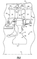
- FIG. 2 schematically illustrates a High Pressure Turbine (HPT) section of the gas turbine engine 10 having a turbine disc assembly 12 within the turbine section T disposed along the engine longitudinal axis X.
- HPT High Pressure Turbine
- the HPT section generally includes a blade outer air seal assembly 16 with a rotor assembly 18 disposed between a forward stationary vane assembly 20 and an aft stationary vane assembly 22.
- Each vane assembly 20, 22 include a plurality of vanes 24 circumferentially disposed around an inner vane support 26.
- the vanes 24 of each assembly 20, 22 extend between the inner vane support 26F, 26A and an outer vane platform 28F, 28A.
- the outer vane platforms 28F, 28A are attached to an engine case 32.
- the rotor assembly 18 includes a plurality of blades 34 circumferentially disposed around a rotor disk 36.
- the rotor disk 36 generally includes a hub 42, a rim 44, and a web 46 which extends therebetween.
- Each blade 34 generally includes an attachment section 50, a platform section 52 and an airfoil section 54 along a longitudinal axis B.
- the outer edge of each airfoil section 54 is a blade tip 540 which is adjacent the blade outer air seal assembly 16.
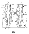
- the airfoil section 54 defines a suction side 54S and a pressure side 54P relative an axis of rotation X of the disk 36.
- Each of the blades 34 is received within a blade slot 48 formed within the rim 44 of the rotor disk 36.
- the blade slot 48 includes a contour such as a fir-tree or bulb type which corresponds with a contour of the attachment section 50 to provide engagement therewith.
- Each blade 34 further includes a neck section 56 between the attachment section 50 and the platform section 52.
- the platform section 52 of one blade 34A abuts a platform section 52 of a second blade 34B such that underplatform section hardware 58 (illustrated schematically) such as a damper and featherseal may be located at the interface therebetween to seal the rim cavity 60 between the rim 44 and the platform sections 52.
- Platform cooling apertures 62 are located through the platform section 52 to provide a cooling airflow to the platform sections 52 on both the pressure side and the suction side.
- An internal airfoil cooling passage 64 extends through the blade 34 to communicate cooling airflow from within the blade slot 48 through cooling apertures 65 located adjacent the airfoil section trailing edge 54T ( Figures 2 , 4A, and 4B ).
- a leading edge buttress 56L and a trailing edge buttress 56T are generally located in the neck section 56 generally adjacent an airfoil leading edge 54L and an airfoil trailing edge 54T.
- Dead mass exists within the leading edge buttress 56L and the trailing edge buttress 56T as a byproduct of other requirements.
- the dead mass in the leading edge buttress 56L and the trailing edge buttress 56T is bounded by the platform section 52, the internal airfoil cooling passage 64 (for the trailing edge buttress 54T), and a respective underplatform fillet 66L, 66T.
- the radius and location of the underplatform fillet 66L, 66T is defined generally to prevent a platform leading edge 52L and a platform trailing edge 52T from curling toward the attachment section 50.
- the internal cooling passage 64 transitions smoothly away from the underplatform fillet 66T so that the cooling air transitions smoothly from the neck section 56 into the airfoil section 54.
- the loads induced by the platform section 52 are transferred into the neck section 56 through the underplatform fillet 66L, 66T while loads induced in the airfoil section 54 are transferred into the neck section 56 along the wall of the internal airfoil cooling passage 64.
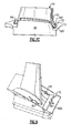
- a blade weight reduction region 70 includes an aperture 72 located in either or both of the trailing edge buttress 56T and the leading edge buttress 56L ( Figures 8A and 8B ).
- the aperture 72 may extend at least partially into the neck section 56 from either or both of the pressure side and the suction side of the blade 34. That is, the aperture may essentially define a dimple or other blade weight reduction region 70 of any shape.
- the aperture 72 may extend completely though the neck section 56 as the aperture 72 spans the pressure side and the suction side of the blade 34 to thereby form an open truss-like feature.
- the blade weight reduction region 70 is bounded by the platform section 52, the internal airfoil cooling passage 64, and the underplatform fillet 66T to transfer loads in the airfoil section 54 and platform section 52 into the neck section 56 then into the attachment section 50.
- Any aperture, dimple or other material removal within the blade weight reduction region 70 may thereby be interpreted as the aperture 72 as defined herein.
- the area through which the aperture 72 passes is typically slightly thicker than the adjacent neck area 56 which further increases the weight reduction (contour also illustrated in Figure 7C ). This weight reduction may alternatively or additionally be located within the leading edge buttress 56L ( Figures 8A and 8B ).
- the aperture 72 is illustrated as a cylinder which is generally circular in cross-section, it should be understood that other cross-section shapes may alternatively or additionally be provided.
- the aperture 72 may be formed early during the casting process by inserting a quartz rod into the wax die or later during the machining process by drilling with an EDM electrode.
- the aperture 72 may supplement the platform cooling apertures 62 through the incorporation of aperture platform cooling apertures 62A. That is, the rim cavity 60 ( Figure 3 ) supplies cooling airflow into the aperture 72 which thereby communicates the cooling airflow from the aperture 72 through the platform section 52 by way of the aperture platform cooling apertures 62A.
- the aperture platform cooling apertures 62A extend through the platform trailing edge 56T.
- the blade weight reduction feature removes weight from the blade without adversely affecting the load or stresses in the blade.
Landscapes
- Engineering & Computer Science (AREA)
- Mechanical Engineering (AREA)
- General Engineering & Computer Science (AREA)
- Architecture (AREA)
- Turbine Rotor Nozzle Sealing (AREA)
Abstract
Description
- The present invention relates to a gas turbine engine, and more particularly to a rotor blade thereof.
- Gas turbine engines often include a multiple of rotor assemblies within a fan, compressor and turbine section. Each rotor assembly has a multitude of blades attached about a circumference of a rotor disc. Each of the blades is spaced a distance apart from adjacent blades to accommodate movement and expansion during operation. Each blade includes an attachment section that attaches to the rotor disc, a platform section, and an airfoil section that extends radially outwardly from the platform section.
- When engine weight becomes a concern, emphasis is directed toward the reduction of blade weight since every one kilogram of weight in the set of blades is worth about three kilograms of weight in the rotor disk due to centrifugal forces. Weight is typically removed from the blade by thinning airfoil walls and ribs until a minimum thickness is achieved from a manufacturing and structural standpoint.
- Although there may be significant mass in the attachment region of the blade, this mass is required to prevent fracture of the blade when centrifugal and airfoil bending loads are applied.
- A rotor blade for a turbine engine according to a first aspect of the present invention includes: an edge buttress having an aperture, the aperture extends at least partially through the edge buttress.
- A rotor blade for a turbine engine according to a further aspect of the present invention includes: a platform section; an airfoil section which extends from the platform section; a neck section which extends from the platform section opposite the airfoil section, the neck section and the airfoil section contains an internal airfoil cooling passage; and an underplatform fillet adjacent the neck section and the platform section. The platform section, the internal airfoil cooling passage, and the underplatform fillet defines a truss shape which bounds an aperture. The truss shape may be generally triangular in shape. The aperture may extend completely through the neck section. The aperture may define a cylinder. The platform section may define the underplatform fillet which may be at least partially hook-shaped.
- A method of reducing a rotor blade weight according to a further aspect of the present invention includes: removing material from within a truss area bounded by a platform section, an internal airfoil cooling passage, and an underplatform fillet of a rotor blade.
- The various features and advantages of this invention will become apparent to those skilled in the art from the following detailed description of the disclosed non-limiting embodiment. The drawings that accompany the detailed description can be briefly described as follows:
-
Figure 1 is a schematic illustration of a gas turbine engine; -
Figure 2 is a general sectional diagrammatic view of a gas turbine engine HPT section of the engine ofFigure 1 ; -
Figure 3 is an expanded front sectional view of a rotor blade mounted to a rotor disc; -
Figure 4A is a pressure side partial phantom view of a rotor blade; -
Figure 4B is a suction side partial phantom view of a rotor blade; -
Figure 5 is a pressure side view of a rotor blade illustrating a dead weight region; -
Figure 6 is a pressure side view of a rotor blade illustrating a truss structure defined about the dead weight region ofFigure 5 ; -
Figure 7A is a pressure side partial phantom view of a rotor blade illustrating a weight reduction feature; -
Figure 7B is a suction side partial phantom view of a rotor blade illustrating a weight reduction feature; -
Figure 7C is a pressure side rotor blade surface contour view illustrating a weight reduction feature; -
Figure 8A is a pressure side partial phantom view of a rotor blade illustrating weight reduction feature; -
Figure 8B is a perspective phantom view of a rotor blade illustrating the weight reduction feature; and -
Figure 9 is a perspective phantom view of a rotor blade illustrating the weight reduction feature with supplemental platform cooling apertures that communicate with the weight reduction feature. -
Figure 1 schematically illustrates agas turbine engine 10 which generally includes a fan section F, a compressor section C, a combustor section G, a turbine section T, an augmentor section A, and an exhaust duct assembly E. The compressor section C, combustor section G, and turbine section T are generally referred to as the core engine. An engine longitudinal axis X is centrally disposed and extends longitudinally through these sections. Although a particular gas turbine engine configuration is illustrated and described in the disclosed embodiment, other turbine engine types will also benefit herefrom. -
Figure 2 schematically illustrates a High Pressure Turbine (HPT) section of thegas turbine engine 10 having aturbine disc assembly 12 within the turbine section T disposed along the engine longitudinal axis X. It should be understood that a multiple of discs may be contained within each engine section and that although the HPT section is illustrated and described in the disclosed embodiment, other sections which have other blades which have a truss-like structure within a neck section such as low pressure turbine blades, will also benefit herefrom. - The HPT section generally includes a blade outer
air seal assembly 16 with arotor assembly 18 disposed between a forwardstationary vane assembly 20 and an aftstationary vane assembly 22. Eachvane assembly vanes 24 circumferentially disposed around an inner vane support 26. Thevanes 24 of eachassembly inner vane support outer vane platform outer vane platforms engine case 32. - The
rotor assembly 18 includes a plurality ofblades 34 circumferentially disposed around arotor disk 36. Therotor disk 36 generally includes ahub 42, arim 44, and aweb 46 which extends therebetween. Eachblade 34 generally includes anattachment section 50, aplatform section 52 and anairfoil section 54 along a longitudinal axis B. The outer edge of eachairfoil section 54 is ablade tip 540 which is adjacent the blade outerair seal assembly 16. - Referring to
Figure 3 , theairfoil section 54 defines asuction side 54S and apressure side 54P relative an axis of rotation X of thedisk 36. Each of theblades 34 is received within ablade slot 48 formed within therim 44 of therotor disk 36. Theblade slot 48 includes a contour such as a fir-tree or bulb type which corresponds with a contour of theattachment section 50 to provide engagement therewith. - Each
blade 34 further includes aneck section 56 between theattachment section 50 and theplatform section 52. Theplatform section 52 of oneblade 34A abuts aplatform section 52 of a second blade 34B such that underplatform section hardware 58 (illustrated schematically) such as a damper and featherseal may be located at the interface therebetween to seal the rim cavity 60 between therim 44 and theplatform sections 52.Platform cooling apertures 62 are located through theplatform section 52 to provide a cooling airflow to theplatform sections 52 on both the pressure side and the suction side. An internalairfoil cooling passage 64 extends through theblade 34 to communicate cooling airflow from within theblade slot 48 throughcooling apertures 65 located adjacent the airfoilsection trailing edge 54T (Figures 2 ,4A, and 4B ). - Referring to
Figures 4A and 4B , a leadingedge buttress 56L and atrailing edge buttress 56T are generally located in theneck section 56 generally adjacent anairfoil leading edge 54L and anairfoil trailing edge 54T. Dead mass exists within the leadingedge buttress 56L and thetrailing edge buttress 56T as a byproduct of other requirements. The dead mass in the leadingedge buttress 56L and thetrailing edge buttress 56T is bounded by theplatform section 52, the internal airfoil cooling passage 64 (for thetrailing edge buttress 54T), and arespective underplatform fillet underplatform fillet platform leading edge 52L and aplatform trailing edge 52T from curling toward theattachment section 50. - The
internal cooling passage 64 transitions smoothly away from theunderplatform fillet 66T so that the cooling air transitions smoothly from theneck section 56 into theairfoil section 54. The loads induced by theplatform section 52 are transferred into theneck section 56 through theunderplatform fillet airfoil section 54 are transferred into theneck section 56 along the wall of the internalairfoil cooling passage 64. This results in a dead mass region between theunderplatform fillet 66T and the internal airfoil cooling passage 64 (Figure 5 ). That is, a truss T is essentially defined by theplatform section 52, the wall of the internalairfoil cooling passage 64, and theunderplatform fillet 66T (Figure 6 ). Applicant has determined that this dead mass can be removed without adversely affecting the load or stresses in theblade 34. - Referring to
Figures 7A and 7B , a bladeweight reduction region 70 includes anaperture 72 located in either or both of thetrailing edge buttress 56T and the leadingedge buttress 56L (Figures 8A and 8B ). Theaperture 72 may extend at least partially into theneck section 56 from either or both of the pressure side and the suction side of theblade 34. That is, the aperture may essentially define a dimple or other bladeweight reduction region 70 of any shape. Alternatively, theaperture 72 may extend completely though theneck section 56 as theaperture 72 spans the pressure side and the suction side of theblade 34 to thereby form an open truss-like feature. That is, the bladeweight reduction region 70 is bounded by theplatform section 52, the internalairfoil cooling passage 64, and the underplatform fillet 66T to transfer loads in theairfoil section 54 andplatform section 52 into theneck section 56 then into theattachment section 50. Any aperture, dimple or other material removal within the bladeweight reduction region 70 may thereby be interpreted as theaperture 72 as defined herein. The area through which theaperture 72 passes is typically slightly thicker than theadjacent neck area 56 which further increases the weight reduction (contour also illustrated inFigure 7C ). This weight reduction may alternatively or additionally be located within the leading edge buttress 56L (Figures 8A and 8B ). - Although the
aperture 72 is illustrated as a cylinder which is generally circular in cross-section, it should be understood that other cross-section shapes may alternatively or additionally be provided. In one non-limiting embodiment, theaperture 72 may be formed early during the casting process by inserting a quartz rod into the wax die or later during the machining process by drilling with an EDM electrode. - Referring to
Figure 9 , theaperture 72 may supplement theplatform cooling apertures 62 through the incorporation of apertureplatform cooling apertures 62A. That is, the rim cavity 60 (Figure 3 ) supplies cooling airflow into theaperture 72 which thereby communicates the cooling airflow from theaperture 72 through theplatform section 52 by way of the apertureplatform cooling apertures 62A. In one non-limiting embodiment, the apertureplatform cooling apertures 62A extend through theplatform trailing edge 56T. - The blade weight reduction feature removes weight from the blade without adversely affecting the load or stresses in the blade.
- It should be understood that relative positional terms such as "forward," "aft," "upper," "lower," "above," "below," and the like are with reference to the normal operational attitude of the vehicle and should not be considered otherwise limiting.
- It should be understood that although a particular component arrangement is disclosed in the illustrated embodiment, other arrangements will benefit from the instant invention.
- Although particular step sequences are shown, described, and claimed, it should be understood that steps may be performed in any order, separated or combined unless otherwise indicated and will still benefit from the present invention.
- The foregoing description is exemplary rather than defined by the limitations within. Many modifications and variations are possible in light of the above teachings. Non-limiting embodiments are disclosed herein, however, one of ordinary skill in the art would recognize that certain modifications would come within the scope of this invention. It is, therefore, to be understood that within the scope of the appended claims, the invention may be practiced otherwise than as specifically described. For that reason the following claims should be studied to determine the true scope and content of this invention.
Claims (15)
- A rotor blade (34) for a turbine engine comprising:an edge buttress (56L;56T) having an aperture (72), said aperture (72) extending at least partially through said edge buttress (56L;56T).
- The rotor blade as recited in claim 1, wherein said rotor blade (34) is a high pressure turbine blade.
- The rotor blade as recited in claim 1 or 2, wherein said aperture (72) extends completely through a neck section (56) adjacent said edge buttress (56L;56T).
- The rotor blade as recited in any preceding claim, wherein said aperture (72) is circular in cross-section.
- The rotor blade as recited in any preceding claim, wherein said edge buttress is a trailing edge buttress (56T).
- The rotor blade as recited in any preceding claim, wherein said edge buttress is a leading edge buttress (56L).
- The rotor blade as recited in any preceding claim, wherein said aperture (72) is located adjacent but does not communicate with an internal airfoil cooling passage (64) within a neck section (56) and an airfoil section (54) of said rotor blade (34).
- The rotor blade as recited in any preceding claim, further comprising an aperture platform cooling aperture (62A) in communication with said aperture (72).
- The rotor blade as recited in claim 8, wherein said aperture platform cooling aperture (62A) is in communication with a platform section (52) of said rotor blade (34).
- The rotor blade as recited in any preceding claim, wherein said edge buttress (56T) is located adjacent a neck section (56) between a platform section (52) and an attachment section of said rotor blade (34), said aperture (72) extends completely through said neck section (56).
- A method of reducing rotor blade weight comprising:removing material from within a truss area bounded by a platform section (52), an internal airfoil cooling passage (64), and an underplatform fillet (66T) of a rotor blade (34).
- The method as recited in claim 11, removing material to define an aperture (72).
- The method as recited in claim 12, removing material to define a cylindrical aperture (72).
- The method as recited in any of claims 11 to 13, removing material to define an aperture (72) which extends completely though a neck section (56) of the rotor blade (34).
- The method as recited in claim 14, forming an aperture platform cooling aperture (62A) though the platform section (52), the aperture platform cooling aperture (62A) in communication with the aperture (72) which extends completely though the neck section (56) of the rotor blade (34).
Applications Claiming Priority (1)
| Application Number | Priority Date | Filing Date | Title |
|---|---|---|---|
| US12/103,779 US8282354B2 (en) | 2008-04-16 | 2008-04-16 | Reduced weight blade for a gas turbine engine |
Publications (2)
| Publication Number | Publication Date |
|---|---|
| EP2110513A2 true EP2110513A2 (en) | 2009-10-21 |
| EP2110513A3 EP2110513A3 (en) | 2012-05-09 |
Family
ID=40592993
Family Applications (1)
| Application Number | Title | Priority Date | Filing Date |
|---|---|---|---|
| EP09250721A Withdrawn EP2110513A3 (en) | 2008-04-16 | 2009-03-13 | Reduced weight blade for a gas turbine engine |
Country Status (2)
| Country | Link |
|---|---|
| US (1) | US8282354B2 (en) |
| EP (1) | EP2110513A3 (en) |
Cited By (6)
| Publication number | Priority date | Publication date | Assignee | Title |
|---|---|---|---|---|
| EP2436882A3 (en) * | 2010-09-30 | 2014-02-26 | Rolls-Royce plc | Cooled rotor blade |
| EP2781697A1 (en) * | 2013-03-20 | 2014-09-24 | Siemens Aktiengesellschaft | A turbomachine component with a stress relief cavity and method of forming such a cavity |
| GB2522999A (en) * | 2013-12-23 | 2015-08-12 | Snecma | Blade comprising a support, provided with a portion with a depression |
| EP2610437A3 (en) * | 2011-12-30 | 2017-06-21 | General Electric Company | Turbine rotor blade platform cooling |
| US10458257B2 (en) | 2013-12-23 | 2019-10-29 | Safran Aircraft Engines | Blade comprising a shank, provided with a depressed portion |
| FR3082231A1 (en) * | 2018-06-11 | 2019-12-13 | Safran Aircraft Engines | TURBOMACHINE WHEEL |
Families Citing this family (1)
| Publication number | Priority date | Publication date | Assignee | Title |
|---|---|---|---|---|
| US10294795B2 (en) * | 2010-04-28 | 2019-05-21 | United Technologies Corporation | High pitch-to-chord turbine airfoils |
Family Cites Families (27)
| Publication number | Priority date | Publication date | Assignee | Title |
|---|---|---|---|---|
| CH626947A5 (en) * | 1978-03-02 | 1981-12-15 | Bbc Brown Boveri & Cie | |
| FR2527260A1 (en) * | 1982-05-18 | 1983-11-25 | Snecma | RETRACTABLE DAMPING DEVICE FOR AUBES OF A TURBOMACHINE |
| US4936749A (en) | 1988-12-21 | 1990-06-26 | General Electric Company | Blade-to-blade vibration damper |
| US5215442A (en) * | 1991-10-04 | 1993-06-01 | General Electric Company | Turbine blade platform damper |
| US5261790A (en) * | 1992-02-03 | 1993-11-16 | General Electric Company | Retention device for turbine blade damper |
| GB2455431B (en) * | 1994-11-30 | 2009-11-18 | Rolls Royce Plc | Split shank rotor blade |
| US6183195B1 (en) | 1999-02-04 | 2001-02-06 | Pratt & Whitney Canada Corp. | Single slot impeller bleed |
| US6227801B1 (en) | 1999-04-27 | 2001-05-08 | Pratt & Whitney Canada Corp. | Turbine engine having improved high pressure turbine cooling |
| US6441341B1 (en) | 2000-06-16 | 2002-08-27 | General Electric Company | Method of forming cooling holes in a ceramic matrix composite turbine components |
| US6402471B1 (en) | 2000-11-03 | 2002-06-11 | General Electric Company | Turbine blade for gas turbine engine and method of cooling same |
| US6508620B2 (en) | 2001-05-17 | 2003-01-21 | Pratt & Whitney Canada Corp. | Inner platform impingement cooling by supply air from outside |
| US6735956B2 (en) | 2001-10-26 | 2004-05-18 | Pratt & Whitney Canada Corp. | High pressure turbine blade cooling scoop |
| US6647730B2 (en) | 2001-10-31 | 2003-11-18 | Pratt & Whitney Canada Corp. | Turbine engine having turbine cooled with diverted compressor intermediate pressure air |
| US6786696B2 (en) | 2002-05-06 | 2004-09-07 | General Electric Company | Root notched turbine blade |
| US6881036B2 (en) | 2002-09-03 | 2005-04-19 | United Technologies Corporation | Composite integrally bladed rotor |
| US6652222B1 (en) | 2002-09-03 | 2003-11-25 | Pratt & Whitney Canada Corp. | Fan case design with metal foam between Kevlar |
| US6832893B2 (en) | 2002-10-24 | 2004-12-21 | Pratt & Whitney Canada Corp. | Blade passive cooling feature |
| US6991428B2 (en) | 2003-06-12 | 2006-01-31 | Pratt & Whitney Canada Corp. | Fan blade platform feature for improved blade-off performance |
| GB0321056D0 (en) | 2003-09-09 | 2003-10-08 | Rolls Royce Plc | Joint arrangement |
| US7001150B2 (en) | 2003-10-16 | 2006-02-21 | Pratt & Whitney Canada Corp. | Hollow turbine blade stiffening |
| US7252481B2 (en) | 2004-05-14 | 2007-08-07 | Pratt & Whitney Canada Corp. | Natural frequency tuning of gas turbine engine blades |
| US7153102B2 (en) | 2004-05-14 | 2006-12-26 | Pratt & Whitney Canada Corp. | Bladed disk fixing undercut |
| US7156621B2 (en) | 2004-05-14 | 2007-01-02 | Pratt & Whitney Canada Corp. | Blade fixing relief mismatch |
| US7121802B2 (en) | 2004-07-13 | 2006-10-17 | General Electric Company | Selectively thinned turbine blade |
| US7229249B2 (en) | 2004-08-27 | 2007-06-12 | Pratt & Whitney Canada Corp. | Lightweight annular interturbine duct |
| US7300246B2 (en) | 2004-12-15 | 2007-11-27 | Pratt & Whitney Canada Corp. | Integrated turbine vane support |
| US7322797B2 (en) | 2005-12-08 | 2008-01-29 | General Electric Company | Damper cooled turbine blade |
-
2008
- 2008-04-16 US US12/103,779 patent/US8282354B2/en active Active
-
2009
- 2009-03-13 EP EP09250721A patent/EP2110513A3/en not_active Withdrawn
Cited By (11)
| Publication number | Priority date | Publication date | Assignee | Title |
|---|---|---|---|---|
| EP2436882A3 (en) * | 2010-09-30 | 2014-02-26 | Rolls-Royce plc | Cooled rotor blade |
| US9074484B2 (en) | 2010-09-30 | 2015-07-07 | Rolls-Royce Plc | Cooled rotor blade |
| EP2610437A3 (en) * | 2011-12-30 | 2017-06-21 | General Electric Company | Turbine rotor blade platform cooling |
| EP2781697A1 (en) * | 2013-03-20 | 2014-09-24 | Siemens Aktiengesellschaft | A turbomachine component with a stress relief cavity and method of forming such a cavity |
| WO2014146827A1 (en) * | 2013-03-20 | 2014-09-25 | Siemens Aktiengesellschaft | A turbomachine component with a stress relief cavity |
| US10001017B2 (en) | 2013-03-20 | 2018-06-19 | Siemens Aktiengesellschaft | Turbomachine component with a stress relief cavity |
| CN105283639B (en) * | 2013-03-20 | 2019-04-30 | 西门子公司 | Turbine Components with Strain Relief Cavities |
| GB2522999A (en) * | 2013-12-23 | 2015-08-12 | Snecma | Blade comprising a support, provided with a portion with a depression |
| GB2522999B (en) * | 2013-12-23 | 2016-05-18 | Snecma | Blade comprising a support, provided with a portion with a depression |
| US10458257B2 (en) | 2013-12-23 | 2019-10-29 | Safran Aircraft Engines | Blade comprising a shank, provided with a depressed portion |
| FR3082231A1 (en) * | 2018-06-11 | 2019-12-13 | Safran Aircraft Engines | TURBOMACHINE WHEEL |
Also Published As
| Publication number | Publication date |
|---|---|
| US20090263251A1 (en) | 2009-10-22 |
| US8282354B2 (en) | 2012-10-09 |
| EP2110513A3 (en) | 2012-05-09 |
Similar Documents
| Publication | Publication Date | Title |
|---|---|---|
| EP0731874B1 (en) | Hollow fan blade dovetail | |
| EP1688587B1 (en) | Funnel fillet turbine stage | |
| EP2110513A2 (en) | Reduced weight blade for a gas turbine engine | |
| US6561758B2 (en) | Methods and systems for cooling gas turbine engine airfoils | |
| US8007229B2 (en) | Variable area turbine vane arrangement | |
| CA2313929C (en) | Reduced-stress compressor blisk flowpath | |
| EP2374997B1 (en) | Component for a gas turbine engine | |
| EP2305954B1 (en) | Internally damped blade | |
| JP3844324B2 (en) | Squeezer for gas turbine engine turbine blade and gas turbine engine turbine blade | |
| EP2412926B1 (en) | Hollow blade for a gas turbine | |
| US10907648B2 (en) | Airfoil with maximum thickness distribution for robustness | |
| EP2867472B1 (en) | Turbine vane | |
| EP1674659B1 (en) | Turbine nozzle with bullnose step-down platform | |
| EP1895100B1 (en) | Conformal tip baffle airfoil | |
| EP2369139B1 (en) | Nozzle segment with reduced weight flange | |
| EP2110514B1 (en) | Asymmetrical rotor blade fir tree attachment | |
| JP2007064221A (en) | Optimization of stator blade profile | |
| EP2484867B1 (en) | Rotating component of a turbine engine | |
| US10294805B2 (en) | Gas turbine engine integrally bladed rotor with asymmetrical trench fillets | |
| US6485262B1 (en) | Methods and apparatus for extending gas turbine engine airfoils useful life | |
| JP2004324646A (en) | Method and apparatus for structurally supporting an airfoil tip | |
| EP1801347B1 (en) | High pressure turbine disk hub with curved hub surface and method | |
| EP3441566A1 (en) | Airfoil with maximum thickness distribution for robustness | |
| EP1818503B1 (en) | Turbine airfoil with weight reduction plenum | |
| WO2017146724A1 (en) | Damping for fabricated hollow turbine blades |
Legal Events
| Date | Code | Title | Description |
|---|---|---|---|
| PUAI | Public reference made under article 153(3) epc to a published international application that has entered the european phase |
Free format text: ORIGINAL CODE: 0009012 |
|
| AK | Designated contracting states |
Kind code of ref document: A2 Designated state(s): AT BE BG CH CY CZ DE DK EE ES FI FR GB GR HR HU IE IS IT LI LT LU LV MC MK MT NL NO PL PT RO SE SI SK TR |
|
| AX | Request for extension of the european patent |
Extension state: AL BA RS |
|
| PUAL | Search report despatched |
Free format text: ORIGINAL CODE: 0009013 |
|
| AK | Designated contracting states |
Kind code of ref document: A3 Designated state(s): AT BE BG CH CY CZ DE DK EE ES FI FR GB GR HR HU IE IS IT LI LT LU LV MC MK MT NL NO PL PT RO SE SI SK TR |
|
| AX | Request for extension of the european patent |
Extension state: AL BA RS |
|
| RIC1 | Information provided on ipc code assigned before grant |
Ipc: F01D 5/14 20060101AFI20120402BHEP |
|
| 17P | Request for examination filed |
Effective date: 20121030 |
|
| AKX | Designation fees paid |
Designated state(s): DE GB |
|
| STAA | Information on the status of an ep patent application or granted ep patent |
Free format text: STATUS: THE APPLICATION HAS BEEN WITHDRAWN |
|
| 18W | Application withdrawn |
Effective date: 20131213 |