EP2110227B1 - A device for supporting counter-rotating elements - Google Patents
A device for supporting counter-rotating elements Download PDFInfo
- Publication number
- EP2110227B1 EP2110227B1 EP08425267A EP08425267A EP2110227B1 EP 2110227 B1 EP2110227 B1 EP 2110227B1 EP 08425267 A EP08425267 A EP 08425267A EP 08425267 A EP08425267 A EP 08425267A EP 2110227 B1 EP2110227 B1 EP 2110227B1
- Authority
- EP
- European Patent Office
- Prior art keywords
- counter
- rotating elements
- plate
- actuator
- previous
- Prior art date
- Legal status (The legal status is an assumption and is not a legal conclusion. Google has not performed a legal analysis and makes no representation as to the accuracy of the status listed.)
- Not-in-force
Links
Images
Classifications
-
- B—PERFORMING OPERATIONS; TRANSPORTING
- B23—MACHINE TOOLS; METAL-WORKING NOT OTHERWISE PROVIDED FOR
- B23K—SOLDERING OR UNSOLDERING; WELDING; CLADDING OR PLATING BY SOLDERING OR WELDING; CUTTING BY APPLYING HEAT LOCALLY, e.g. FLAME CUTTING; WORKING BY LASER BEAM
- B23K20/00—Non-electric welding by applying impact or other pressure, with or without the application of heat, e.g. cladding or plating
- B23K20/10—Non-electric welding by applying impact or other pressure, with or without the application of heat, e.g. cladding or plating making use of vibrations, e.g. ultrasonic welding
- B23K20/103—Non-electric welding by applying impact or other pressure, with or without the application of heat, e.g. cladding or plating making use of vibrations, e.g. ultrasonic welding using a roller
-
- B—PERFORMING OPERATIONS; TRANSPORTING
- B29—WORKING OF PLASTICS; WORKING OF SUBSTANCES IN A PLASTIC STATE IN GENERAL
- B29C—SHAPING OR JOINING OF PLASTICS; SHAPING OF MATERIAL IN A PLASTIC STATE, NOT OTHERWISE PROVIDED FOR; AFTER-TREATMENT OF THE SHAPED PRODUCTS, e.g. REPAIRING
- B29C65/00—Joining or sealing of preformed parts, e.g. welding of plastics materials; Apparatus therefor
- B29C65/02—Joining or sealing of preformed parts, e.g. welding of plastics materials; Apparatus therefor by heating, with or without pressure
- B29C65/08—Joining or sealing of preformed parts, e.g. welding of plastics materials; Apparatus therefor by heating, with or without pressure using ultrasonic vibrations
- B29C65/083—Joining or sealing of preformed parts, e.g. welding of plastics materials; Apparatus therefor by heating, with or without pressure using ultrasonic vibrations using a rotary sonotrode or a rotary anvil
- B29C65/087—Joining or sealing of preformed parts, e.g. welding of plastics materials; Apparatus therefor by heating, with or without pressure using ultrasonic vibrations using a rotary sonotrode or a rotary anvil using both a rotary sonotrode and a rotary anvil
-
- B—PERFORMING OPERATIONS; TRANSPORTING
- B29—WORKING OF PLASTICS; WORKING OF SUBSTANCES IN A PLASTIC STATE IN GENERAL
- B29C—SHAPING OR JOINING OF PLASTICS; SHAPING OF MATERIAL IN A PLASTIC STATE, NOT OTHERWISE PROVIDED FOR; AFTER-TREATMENT OF THE SHAPED PRODUCTS, e.g. REPAIRING
- B29C66/00—General aspects of processes or apparatus for joining preformed parts
- B29C66/01—General aspects dealing with the joint area or with the area to be joined
- B29C66/05—Particular design of joint configurations
- B29C66/10—Particular design of joint configurations particular design of the joint cross-sections
- B29C66/13—Single flanged joints; Fin-type joints; Single hem joints; Edge joints; Interpenetrating fingered joints; Other specific particular designs of joint cross-sections not provided for in groups B29C66/11 - B29C66/12
- B29C66/133—Fin-type joints, the parts to be joined being flexible
-
- B—PERFORMING OPERATIONS; TRANSPORTING
- B29—WORKING OF PLASTICS; WORKING OF SUBSTANCES IN A PLASTIC STATE IN GENERAL
- B29C—SHAPING OR JOINING OF PLASTICS; SHAPING OF MATERIAL IN A PLASTIC STATE, NOT OTHERWISE PROVIDED FOR; AFTER-TREATMENT OF THE SHAPED PRODUCTS, e.g. REPAIRING
- B29C66/00—General aspects of processes or apparatus for joining preformed parts
- B29C66/40—General aspects of joining substantially flat articles, e.g. plates, sheets or web-like materials; Making flat seams in tubular or hollow articles; Joining single elements to substantially flat surfaces
- B29C66/41—Joining substantially flat articles ; Making flat seams in tubular or hollow articles
- B29C66/43—Joining a relatively small portion of the surface of said articles
- B29C66/432—Joining a relatively small portion of the surface of said articles for making tubular articles or closed loops, e.g. by joining several sheets ; for making hollow articles or hollow preforms
- B29C66/4322—Joining a relatively small portion of the surface of said articles for making tubular articles or closed loops, e.g. by joining several sheets ; for making hollow articles or hollow preforms by joining a single sheet to itself
-
- B—PERFORMING OPERATIONS; TRANSPORTING
- B29—WORKING OF PLASTICS; WORKING OF SUBSTANCES IN A PLASTIC STATE IN GENERAL
- B29C—SHAPING OR JOINING OF PLASTICS; SHAPING OF MATERIAL IN A PLASTIC STATE, NOT OTHERWISE PROVIDED FOR; AFTER-TREATMENT OF THE SHAPED PRODUCTS, e.g. REPAIRING
- B29C66/00—General aspects of processes or apparatus for joining preformed parts
- B29C66/80—General aspects of machine operations or constructions and parts thereof
- B29C66/81—General aspects of the pressing elements, i.e. the elements applying pressure on the parts to be joined in the area to be joined, e.g. the welding jaws or clamps
- B29C66/816—General aspects of the pressing elements, i.e. the elements applying pressure on the parts to be joined in the area to be joined, e.g. the welding jaws or clamps characterised by the mounting of the pressing elements, e.g. of the welding jaws or clamps
- B29C66/8167—Quick change joining tools or surfaces
-
- B—PERFORMING OPERATIONS; TRANSPORTING
- B29—WORKING OF PLASTICS; WORKING OF SUBSTANCES IN A PLASTIC STATE IN GENERAL
- B29C—SHAPING OR JOINING OF PLASTICS; SHAPING OF MATERIAL IN A PLASTIC STATE, NOT OTHERWISE PROVIDED FOR; AFTER-TREATMENT OF THE SHAPED PRODUCTS, e.g. REPAIRING
- B29C66/00—General aspects of processes or apparatus for joining preformed parts
- B29C66/80—General aspects of machine operations or constructions and parts thereof
- B29C66/83—General aspects of machine operations or constructions and parts thereof characterised by the movement of the joining or pressing tools
- B29C66/834—General aspects of machine operations or constructions and parts thereof characterised by the movement of the joining or pressing tools moving with the parts to be joined
- B29C66/8341—Roller, cylinder or drum types; Band or belt types; Ball types
- B29C66/83411—Roller, cylinder or drum types
- B29C66/83413—Roller, cylinder or drum types cooperating rollers, cylinders or drums
-
- B—PERFORMING OPERATIONS; TRANSPORTING
- B29—WORKING OF PLASTICS; WORKING OF SUBSTANCES IN A PLASTIC STATE IN GENERAL
- B29C—SHAPING OR JOINING OF PLASTICS; SHAPING OF MATERIAL IN A PLASTIC STATE, NOT OTHERWISE PROVIDED FOR; AFTER-TREATMENT OF THE SHAPED PRODUCTS, e.g. REPAIRING
- B29C66/00—General aspects of processes or apparatus for joining preformed parts
- B29C66/80—General aspects of machine operations or constructions and parts thereof
- B29C66/84—Specific machine types or machines suitable for specific applications
- B29C66/849—Packaging machines
-
- B—PERFORMING OPERATIONS; TRANSPORTING
- B29—WORKING OF PLASTICS; WORKING OF SUBSTANCES IN A PLASTIC STATE IN GENERAL
- B29C—SHAPING OR JOINING OF PLASTICS; SHAPING OF MATERIAL IN A PLASTIC STATE, NOT OTHERWISE PROVIDED FOR; AFTER-TREATMENT OF THE SHAPED PRODUCTS, e.g. REPAIRING
- B29C66/00—General aspects of processes or apparatus for joining preformed parts
- B29C66/90—Measuring or controlling the joining process
- B29C66/92—Measuring or controlling the joining process by measuring or controlling the pressure, the force, the mechanical power or the displacement of the joining tools
- B29C66/924—Measuring or controlling the joining process by measuring or controlling the pressure, the force, the mechanical power or the displacement of the joining tools by controlling or regulating the pressure, the force, the mechanical power or the displacement of the joining tools
- B29C66/9241—Measuring or controlling the joining process by measuring or controlling the pressure, the force, the mechanical power or the displacement of the joining tools by controlling or regulating the pressure, the force, the mechanical power or the displacement of the joining tools by controlling or regulating the pressure, the force or the mechanical power
-
- B—PERFORMING OPERATIONS; TRANSPORTING
- B29—WORKING OF PLASTICS; WORKING OF SUBSTANCES IN A PLASTIC STATE IN GENERAL
- B29C—SHAPING OR JOINING OF PLASTICS; SHAPING OF MATERIAL IN A PLASTIC STATE, NOT OTHERWISE PROVIDED FOR; AFTER-TREATMENT OF THE SHAPED PRODUCTS, e.g. REPAIRING
- B29C66/00—General aspects of processes or apparatus for joining preformed parts
- B29C66/90—Measuring or controlling the joining process
- B29C66/92—Measuring or controlling the joining process by measuring or controlling the pressure, the force, the mechanical power or the displacement of the joining tools
- B29C66/924—Measuring or controlling the joining process by measuring or controlling the pressure, the force, the mechanical power or the displacement of the joining tools by controlling or regulating the pressure, the force, the mechanical power or the displacement of the joining tools
- B29C66/9261—Measuring or controlling the joining process by measuring or controlling the pressure, the force, the mechanical power or the displacement of the joining tools by controlling or regulating the pressure, the force, the mechanical power or the displacement of the joining tools by controlling or regulating the displacement of the joining tools
- B29C66/92611—Measuring or controlling the joining process by measuring or controlling the pressure, the force, the mechanical power or the displacement of the joining tools by controlling or regulating the pressure, the force, the mechanical power or the displacement of the joining tools by controlling or regulating the displacement of the joining tools by controlling or regulating the gap between the joining tools
-
- B—PERFORMING OPERATIONS; TRANSPORTING
- B65—CONVEYING; PACKING; STORING; HANDLING THIN OR FILAMENTARY MATERIAL
- B65B—MACHINES, APPARATUS OR DEVICES FOR, OR METHODS OF, PACKAGING ARTICLES OR MATERIALS; UNPACKING
- B65B51/00—Devices for, or methods of, sealing or securing package folds or closures; Devices for gathering or twisting wrappers, or necks of bags
- B65B51/10—Applying or generating heat or pressure or combinations thereof
- B65B51/26—Devices specially adapted for producing transverse or longitudinal seams in webs or tubes
- B65B51/30—Devices, e.g. jaws, for applying pressure and heat, e.g. for subdividing filled tubes
- B65B51/306—Counter-rotating devices
-
- B—PERFORMING OPERATIONS; TRANSPORTING
- B65—CONVEYING; PACKING; STORING; HANDLING THIN OR FILAMENTARY MATERIAL
- B65B—MACHINES, APPARATUS OR DEVICES FOR, OR METHODS OF, PACKAGING ARTICLES OR MATERIALS; UNPACKING
- B65B51/00—Devices for, or methods of, sealing or securing package folds or closures; Devices for gathering or twisting wrappers, or necks of bags
- B65B51/10—Applying or generating heat or pressure or combinations thereof
- B65B51/22—Applying or generating heat or pressure or combinations thereof by friction or ultrasonic or high-frequency electrical means, i.e. by friction or ultrasonic or induction welding
- B65B51/225—Applying or generating heat or pressure or combinations thereof by friction or ultrasonic or high-frequency electrical means, i.e. by friction or ultrasonic or induction welding by ultrasonic welding
-
- Y—GENERAL TAGGING OF NEW TECHNOLOGICAL DEVELOPMENTS; GENERAL TAGGING OF CROSS-SECTIONAL TECHNOLOGIES SPANNING OVER SEVERAL SECTIONS OF THE IPC; TECHNICAL SUBJECTS COVERED BY FORMER USPC CROSS-REFERENCE ART COLLECTIONS [XRACs] AND DIGESTS
- Y10—TECHNICAL SUBJECTS COVERED BY FORMER USPC
- Y10T—TECHNICAL SUBJECTS COVERED BY FORMER US CLASSIFICATION
- Y10T156/00—Adhesive bonding and miscellaneous chemical manufacture
- Y10T156/17—Surface bonding means and/or assemblymeans with work feeding or handling means
- Y10T156/1702—For plural parts or plural areas of single part
- Y10T156/1712—Indefinite or running length work
- Y10T156/1741—Progressive continuous bonding press [e.g., roll couples]
Definitions
- the present disclosure refers to support devices for counter-rotating elements.
- the present disclosure has been developed with particular attention to its possible employment for the support of counter-rotating elements included in ultrasound welding systems.
- counter-rotating elements such as, for example, counter-rotating rollers, counter-rotating wheels, counter-rotating disks.
- Known methods for realising the longitudinal sealing line or "fin" of the tubular wrapping blank include advancing the edges of the tape destined to form the above-said fin through one or more pairs of counter-rotating elements that realise the welding of the edges, typically by thermal welding.
- the device supporting the counter-rotating elements has three functions:
- the invention relates to a support device according to the preamble of claim 1, which is known, e.g., from EP-A-0 705 657 .
- the object of the present invention is to provide such a device.
- reference 10 indicates a support device in its entirety for two counter-rotating elements 12 and 14 rotatable (in opposite directions) around their respective axes X12 and X14, parallel to each other.
- the counter-rotating elements 12 and 14 are the anvil and ultrasonic welding horn, respectively, of an ultrasound welding system.
- this can be the system (or one of the systems) for ultrasound welding destined to form the so-called longitudinal fin of a wrapper of the type commonly denominated "flow-pack".
- the field of application of the device described herein, however, is not limited to application in this context.
- the counter-rotating elements 12 and 14 have an approximately disk shape and are mounted on respective shafts 120, 140.
- Two gear wheels 16 and 18 are splined onto the shafts 120, 140 in the proximity of the counter-rotating elements 12, 14.
- the gears 16 and 18 are coupled together forming a gear pair so that one of the shafts 120, 140 (for example the shaft 120), being pulled in rotation around its respective axis X12 by a motorisation not explicitly shown, pulls in rotation (in the opposite direction) the other shaft (for example, shaft 140) around its respective axis X14 causing the rotation of the elements 12 and 14 in opposite directions.
- the elements 12 and 14 (or at least one of them, for example, the element 12) can be realised so to be replaceable in order to be able to modify the application pattern of the ultrasound front edge in the zone of cooperation between the counter-rotating elements 12 and 14.
- References 22 and 24 indicate two solid support blocks receiving the shaft 120 and the shaft 140 respectively, mounted rotating inside.
- the precise mounting of the shafts inside the support blocks 22 and 24 is actuated through elements (from example bearings) of known type according to known machine construction criteria, which makes their detailed description herein superfluous. This is also valid concerning the transmission of the motion to the shaft 140 and/or the application of the wave front of ultrasonic excitation to the shaft 140 and to the rotating element 14 mounted on its extremity.
- Reference 26 indicates a flat or substantially flat plate connected both to the support block 22 and to the support block 24 (which in the exemplary embodiment illustrated herein are assumed to be parallelepiped prismatic blocks with square or rectangular transverse sections) according to a general bridge-like arrangement.
- plate 26 is fixed to the support blocks 22 and 24 through screws 28. Other fixing means known to one skilled in machine construction may be applied for such purpose.
- cylinders 29 having a centring function are interposed between plate 26 and each of the support blocks 22 and 24. All of this so to insure that the bridge-like connection of plate 26 between the two blocks 22 and 24 is stable and precise, particularly concerning the parallel alignment of the axes X12 and X14 around which the counter-rotating elements 12 and 14 rotate.
- the exemplary embodiment illustrated herein provides for the plate 26 disposed as a bridge-like connection between the support blocks 22 and 24 being unique, preferably with an open structure. Using more than one plate is naturally included within the scope of the present specification.
- the plate or plates 26 (in the following, reference will be made to the presence of only one such plate for simplicity) is realised so to allow flexion in the region extending between the blocks 22 and 24.
- such result is obtained by providing for the intermediate zone between blocks 22 and 24 the plate 26 to have an intermediate portion 260 that is thinner (that is, a so-called zone of lightening) obtained, for example, by forming a grinding relief in the plate, allowing plate 26 to bend with respect to the plane in which it generally lies.
- the bending of plate 26 can allow for a variation of the distance D between the two axes X12 and X14 in the order of 2 mm.
- such quantitative data are for orientative purposes only and should not be interpreted as limiting the scope of the specification.
- plate 26 can be exploited to allow selective distancing of the peripheries of the counter-rotating elements 12 and 14 for the insertion into the interval or gap defined between them of a laminar structure M to be subjected to welding. This could be, for example, the two opposite edges of a tape of sheet material subjected to ultrasound welding for the formation of a tubular "flow-pack" wrapping blank.
- the geometry of the blocks 22 and 24 and that of the plate 26 is such that at rest - that is, in the absence of external solicitations - a gap is present between the peripheries of the counter-rotating elements 12 and 14, for example in the order of 2 mm.
- Such gap can then be annulled by acting on the blocks 22 and 24 (which are connected by plate 26 according to a general elastically re-closable jaw-like configuration) so to bring them together until the gap between the peripheries of the counter-rotating elements 12 and 14 is annulled.
- Such result can be obtained through actuating elements of various natures.
- such result is obtained by connecting the support blocks 22 and 24 through a fluid actuator 32.
- the actuator 32 includes:
- the functioning of the actuator 32 provides for the expansion of chamber 326, contracting axially, when fed with the pressurised fluid and therefore generating an axial force that tends to bring the terminal parts of extremities 322 and 324 (and therefore the blocks 22 and 24) together with a force, the intensity of which can be regulated by acting on the proportional valve 328.
- An actuator of the type described is known, for example, from US-B-6 349 746 .
- the feeding pressure of the actuator 32 can initially be brought up to a first threshold value of, for example, 3 atmospheres so to bring the peripheries of the counter-rotating elements 12 and 14 into contact with each other (virtually annulling the gap between such peripheries).
Abstract
Description
- The present disclosure refers to support devices for counter-rotating elements.
- The present disclosure has been developed with particular attention to its possible employment for the support of counter-rotating elements included in ultrasound welding systems.
- In numerous sectors of the art the need arises for supporting counter-rotating elements such as, for example, counter-rotating rollers, counter-rotating wheels, counter-rotating disks.
- In particular, machines denominated "flow-pack" (at times also denominated "form-fill-seal" or, in short, ffs) for realising single or multiple wrappings formed starting from tape-like wrapping material are widely diffuse in the packaging sector. First the wrapping material is closed to form a tube, bringing into contact and welding together the opposite edges of the tape so to form a tubular blank into which the products are inserted. The tubular blank is then pressed in areas included between successive articles, where transversal sealing lines are formed which are then subjected to cutting so to separate the single confections from each other.
- Known methods for realising the longitudinal sealing line or "fin" of the tubular wrapping blank include advancing the edges of the tape destined to form the above-said fin through one or more pairs of counter-rotating elements that realise the welding of the edges, typically by thermal welding. In such situation, the device supporting the counter-rotating elements has three functions:
- guaranteeing that the counter-rotating elements, although freely rotatable, are maintained with their respective rotational axes parallel to each other and exactly at a predetermined distance,
- allowing the opening or moving apart of the counter-rotating elements (for example, to insert the material to be treated into the interval or gap formed between them) and,
- regulating the pressure exerted together by the counter-rotating elements on the treated material advancing between them.
- Such aims can be pursued by taking recourse to a wide range of solutions, providing for the respective supporting blocks may slide closer together or farther apart from each other on respective guides through the action of moving means of various nature (micrometric screws, fluid actuators, etc.). It is also known that the counter-rotating elements can constitute part of an ultrasound welding device (see, for example, documents
IT-B-1 160 245 US-B-6 574 944 ). - More specifically, the invention relates to a support device according to the preamble of claim 1, which is known, e.g., from
EP-A-0 705 657 . - The inventors noted that, particularly in the previously-mentioned ultrasound welding applications, the degree of precision of the functioning provided by conventional support devices may be insufficient for providing an ultrasound welding that is completely satisfactory from the qualitative point of view, mainly concerning the possibility of maintaining the welding characteristics constant in time.
- Therefore the need is felt for support devices for counter-rotating elements capable of overcoming such insufficiencies shown by the devices of known type.
- The object of the present invention is to provide such a device.
- According to the present invention such object is achieved by means of a device having the features specifically recalled in the claims that follow. The claims are an integral part of the technical disclosure provided herein relative to the invention.
- The invention will now be described, by way of non-limiting example only, with reference to the enclosed drawings, wherein:
-
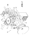
figure 1 is a general prospective view of a device of the type described herein, -
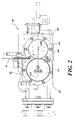
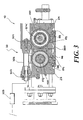
figure 2 is an extremity view of the device described herein, and -
figure 3 is a section along the line III-III offigure 1 . - In the following description, various specific details are illustrated to provide a thorough understanding of the embodiments. The embodiments can be practiced without one or more of the specific details, or with other methods, components, materials, etc. In other instances, known structures, materials or operations are not shown or described in detail to avoid obscuring the various aspects of the embodiments.
- Reference throughout this specification to "one embodiment" or "an embodiment" means that a particular feature, structure or characteristic described in connection with the embodiment is included in at least one embodiment. Thus, the appearance of phrases such as "in one embodiment" or "in an embodiment", possibly present in various places throughout this specification do not necessarily refer to the same embodiment. Furthermore, the particular features, structures or characteristics may be combined in any suitable manner in one or more embodiments, as defined in the appended claims.
- In the figures in the enclosed drawings,
reference 10 indicates a support device in its entirety for twocounter-rotating elements - In one embodiment, the
counter-rotating elements - In one embodiment, this can be the system (or one of the systems) for ultrasound welding destined to form the so-called longitudinal fin of a wrapper of the type commonly denominated "flow-pack". The field of application of the device described herein, however, is not limited to application in this context.
- In the embodiment illustrated herein, the
counter-rotating elements respective shafts gear wheels shafts counter-rotating elements gears shafts 120, 140 (for example the shaft 120), being pulled in rotation around its respective axis X12 by a motorisation not explicitly shown, pulls in rotation (in the opposite direction) the other shaft (for example, shaft 140) around its respective axis X14 causing the rotation of theelements - The solutions cited herein by way of example (
motorised shaft 120pulling shaft 140 by way of thegear pair 16, 18) can be applied in the case of an ultrasound welding system wherein the rotatingelement 12 and the rotatingelement 14 are the anvil and welding horn respectively. The fact that theshaft 140 is pulled in rotation by theshaft 120 by way of thegear pair shaft 140 and by the rotatingelement 14 mounted on its extremity in the form of a horn for the application of the ultrasonic vibration to the welding zone identified by the cooperation point of the peripheries of theelements - The
elements 12 and 14 (or at least one of them, for example, the element 12) can be realised so to be replaceable in order to be able to modify the application pattern of the ultrasound front edge in the zone of cooperation between thecounter-rotating elements -
References shaft 120 and theshaft 140 respectively, mounted rotating inside. The precise mounting of the shafts inside thesupport blocks shaft 140 and/or the application of the wave front of ultrasonic excitation to theshaft 140 and to the rotatingelement 14 mounted on its extremity. -
Reference 26 indicates a flat or substantially flat plate connected both to thesupport block 22 and to the support block 24 (which in the exemplary embodiment illustrated herein are assumed to be parallelepiped prismatic blocks with square or rectangular transverse sections) according to a general bridge-like arrangement. - In the illustrated
embodiment plate 26 is fixed to thesupport blocks screws 28. Other fixing means known to one skilled in machine construction may be applied for such purpose. In the illustrated embodiment,cylinders 29 having a centring function are interposed betweenplate 26 and each of thesupport blocks plate 26 between the twoblocks counter-rotating elements - The exemplary embodiment illustrated herein provides for the
plate 26 disposed as a bridge-like connection between thesupport blocks - The plate or plates 26 (in the following, reference will be made to the presence of only one such plate for simplicity) is realised so to allow flexion in the region extending between the
blocks - In the exemplary embodiment illustrated herein (as can be best appreciated in the view in section in
figure 3 ) such result is obtained by providing for the intermediate zone betweenblocks plate 26 to have anintermediate portion 260 that is thinner (that is, a so-called zone of lightening) obtained, for example, by forming a grinding relief in the plate, allowingplate 26 to bend with respect to the plane in which it generally lies. - The result achievable by means of the bending of
plate 26 is that, though preserving their desired position of strict parallelism, the distance D between axes X12 and X14 (and consequently thecounter-rotating elements 12 and 14) can be slightly modified, best observed in the front view infigure 2 . - Indicatively, considering a distance D between the axes X12 and X14 in the order of 96 mm, the bending of
plate 26 can allow for a variation of the distance D between the two axes X12 and X14 in the order of 2 mm. Naturally, such quantitative data are for orientative purposes only and should not be interpreted as limiting the scope of the specification. - The flexibility of
plate 26 can be exploited to allow selective distancing of the peripheries of thecounter-rotating elements - In the exemplary embodiment illustrated herein it is supposed that the geometry of the
blocks plate 26 is such that at rest - that is, in the absence of external solicitations - a gap is present between the peripheries of thecounter-rotating elements - Such gap can then be annulled by acting on the
blocks 22 and 24 (which are connected byplate 26 according to a general elastically re-closable jaw-like configuration) so to bring them together until the gap between the peripheries of thecounter-rotating elements - Such result can be obtained through actuating elements of various natures. In the example of embodiment illustrated herein, such result is obtained by connecting the
support blocks fluid actuator 32. - In the exemplary embodiment illustrated herein, wherein the
plate 26 and theactuator 32 are arranged on opposite sides with respect to the plane passing through the rotational axes X12 and X14, theactuator 32 includes: - two terminal parts of
extremities block 22 and to theblock 24 respectively, and - an
expandable element 326 susceptible of being fed with a fluid under pressure through a feeding line including, for example, aproportional valve 328. - The functioning of the
actuator 32 provides for the expansion ofchamber 326, contracting axially, when fed with the pressurised fluid and therefore generating an axial force that tends to bring the terminal parts ofextremities 322 and 324 (and therefore theblocks 22 and 24) together with a force, the intensity of which can be regulated by acting on theproportional valve 328. An actuator of the type described is known, for example, fromUS-B-6 349 746 . - Starting from the previously-mentioned resting position (
plate 26 not deformed and peripheries of thecounter-rotating elements actuator 32 can initially be brought up to a first threshold value of, for example, 3 atmospheres so to bring the peripheries of thecounter-rotating elements - The possible further increase of the feeding pressure of the
actuator 32 translates into an increase of the force pushing the peripheries of thecounter-rotating elements - The solution described has the advantage of neither requiring the employment of guides or cams to regulate the relative positions of the
blocks counter-rotating elements actuator 32. - Naturally, keeping the underlying principle of the invention constant, the details of realisation and the embodiments may vary, even appreciably, with respect to what has been illustrated by way of non-limiting example only, without departing from the scope of the invention, as defined by the annexed claims.
Claims (13)
- A support device (10) for counter-rotating elements (12, 14) rotatable around respective axes (X12, X14), the device including:- a first (22) and a second (24) support block supporting one (12) and the other (14) of said counter-rotating elements (12, 14) rotatable around said respective axes (X12, X14), and- at least one connecting plate (26), extending bridge-like between said first (22) and second (24) support block, said at least one plate (26) allowing for the variation of the distance between said rotation axes (X12, X14) of said counter-rotating elements (12, 14) through an actuator (32), characterized in that:- said blocks (22, 24) are connected by said at least one plate (26) in an elastically re-closable jaw-like configuration, and- said actuator (32) is able to act on said first (22) and second (24) support blocks to vary the distance between said rotational axes (X12, X14) thanks the flexibility of said at least one plate (26).
- A device according to claim 1, wherein said at least one plate (26) and said actuator (32) are arranged on opposite sides with respect to the plane passing through said rotational axes (X12, X14).
- A device according to any of the claims 1 or 2, wherein said actuator (32) is a fluid actuator.
- A device according to claim 3, wherein said actuator (30) includes an inflatable chamber (326) which, when fed with fluid under pressure, expands, contracting axially.
- A device according to any of the claims 1 to 4, wherein said at least one plate (26) has a flexible portion of reduced section (260) in a position interposed between said first (22) and second (24) support block.
- A device according to any of the previous claims, wherein said at least one plate (26) is fixed by screwing (28) to said first (22) and second (24) support block.
- A device according to any of the previous claims, wherein centring bodies (29) are interposed between said plate (26) and said first (22) and second (24) support block.
- A device according to any of the previous claims, wherein, with said at least one plate (26) in an undeformed state, said counter-rotating elements (12, 14) are spaced apart.
- A device according to claim 8 in combination with any of the claims 1 to 4, wherein said actuator (32) is associated with a regulating device (328) to apply to said actuator (32) an actuating intensity level which produces the bending of said at least one plate (26) to the point of bringing said counter-rotating elements (12, 14) into contact.
- A device according to any of the previous claims, wherein said actuator (32) is associated with a regulating device (328) to apply to said actuator (32) an actuating intensity level such to push said counter-rotating elements (12, 14) against each other with a given force, preferably regulatable.
- A device according to any of the previous claims, wherein said counter-rotating elements (12, 14) are gear-paired together (16, 18).
- A device according to claim 11, wherein one (12) of said counter-rotating elements is motorised and pulls the other (14) of said counter-rotating elements in rotation by means of said gear pairing (16, 18).
- A device according to any of the previous claims, wherein said counter-rotating elements (12, 14) are the anvil and ultrasonic horn of an ultrasound welding system.
Priority Applications (14)
| Application Number | Priority Date | Filing Date | Title |
|---|---|---|---|
| DE602008003095T DE602008003095D1 (en) | 2008-04-18 | 2008-04-18 | Device for supporting mating elements |
| AT08425267T ATE485155T1 (en) | 2008-04-18 | 2008-04-18 | DEVICE FOR SUPPORTING COUNTER-RUN ELEMENTS |
| PL08425267T PL2110227T3 (en) | 2008-04-18 | 2008-04-18 | A device for supporting counter-rotating elements |
| ES08425267T ES2354498T3 (en) | 2008-04-18 | 2008-04-18 | DEVICE TO SUPPORT CONTRARROTATIVE ELEMENTS. |
| EP08425267A EP2110227B1 (en) | 2008-04-18 | 2008-04-18 | A device for supporting counter-rotating elements |
| AU2009237382A AU2009237382B2 (en) | 2008-04-18 | 2009-02-12 | A device for supporting counter-rotating elements |
| BRPI0911791A BRPI0911791A2 (en) | 2008-04-18 | 2009-02-12 | a support device for counter-rotating elements |
| PCT/IB2009/050582 WO2009127976A1 (en) | 2008-04-18 | 2009-02-12 | A device for supporting counter-rotating elements |
| US12/937,921 US8499811B2 (en) | 2008-04-18 | 2009-02-12 | Device for supporting counter-rotating elements |
| CA2721795A CA2721795A1 (en) | 2008-04-18 | 2009-02-12 | A device for supporting counter-rotating elements |
| CN2009801132842A CN102006984B (en) | 2008-04-18 | 2009-02-12 | A device for supporting counter-rotating elements |
| JP2011504576A JP5269979B2 (en) | 2008-04-18 | 2009-02-12 | Device for supporting counter-rotating elements |
| MX2010011163A MX2010011163A (en) | 2008-04-18 | 2009-02-12 | A device for supporting counter-rotating elements. |
| HR20100732T HRP20100732T1 (en) | 2008-04-18 | 2010-12-31 | A device for supporting counter-rotating elements |
Applications Claiming Priority (1)
| Application Number | Priority Date | Filing Date | Title |
|---|---|---|---|
| EP08425267A EP2110227B1 (en) | 2008-04-18 | 2008-04-18 | A device for supporting counter-rotating elements |
Publications (2)
| Publication Number | Publication Date |
|---|---|
| EP2110227A1 EP2110227A1 (en) | 2009-10-21 |
| EP2110227B1 true EP2110227B1 (en) | 2010-10-20 |
Family
ID=39760711
Family Applications (1)
| Application Number | Title | Priority Date | Filing Date |
|---|---|---|---|
| EP08425267A Not-in-force EP2110227B1 (en) | 2008-04-18 | 2008-04-18 | A device for supporting counter-rotating elements |
Country Status (14)
| Country | Link |
|---|---|
| US (1) | US8499811B2 (en) |
| EP (1) | EP2110227B1 (en) |
| JP (1) | JP5269979B2 (en) |
| CN (1) | CN102006984B (en) |
| AT (1) | ATE485155T1 (en) |
| AU (1) | AU2009237382B2 (en) |
| BR (1) | BRPI0911791A2 (en) |
| CA (1) | CA2721795A1 (en) |
| DE (1) | DE602008003095D1 (en) |
| ES (1) | ES2354498T3 (en) |
| HR (1) | HRP20100732T1 (en) |
| MX (1) | MX2010011163A (en) |
| PL (1) | PL2110227T3 (en) |
| WO (1) | WO2009127976A1 (en) |
Families Citing this family (4)
| Publication number | Priority date | Publication date | Assignee | Title |
|---|---|---|---|---|
| ES2354498T3 (en) | 2008-04-18 | 2011-03-15 | Cavanna S.P.A. | DEVICE TO SUPPORT CONTRARROTATIVE ELEMENTS. |
| EP2431155A1 (en) * | 2010-08-23 | 2012-03-21 | Sonotronic Nagel GmbH | Device for welding a tubular bag film |
| IT201800003324A1 (en) | 2018-03-07 | 2019-09-07 | Gima Tt S P A | PROCEDURE FOR MAKING HERMETIC WRAPS AND RELATED MACHINE. |
| IT202000019420A1 (en) * | 2020-08-06 | 2022-02-06 | Tecno Pack S P A | HORIZONTAL PACKAGING MACHINE WITH ADJUSTABLE CUTTING-OVERCUT GROUP |
Family Cites Families (13)
| Publication number | Priority date | Publication date | Assignee | Title |
|---|---|---|---|---|
| IT1160245B (en) | 1983-12-23 | 1987-03-04 | Ferrero Spa | PACKAGING MACHINE FOR ITEMS, PARTICULARLY SWEET PRODUCTS |
| IT1208411B (en) * | 1987-04-28 | 1989-06-12 | Cavanna Spa | JAW GROUP FOR ZIONING PACKAGING MACHINES PARTICULARLY TUBULAR WRAPPING MACHINES OF THE FLOW PACK TYPE AND SIMILAR |
| IT1250241B (en) * | 1991-12-04 | 1995-04-03 | Cavanna Spa | PACKAGING MACHINE, PARTICULARLY FOR THE FORMATION OF ENVELOPES OF THE FLOW-PACK TYPE AND SIMILAR AND RELATED OPERATING PROCEDURE |
| IT1268100B1 (en) * | 1994-10-07 | 1997-02-20 | Stola Spa | DEVICE FOR WELDING MOTOR VEHICLE BODIES OR THEIR SUB-GROUPS. |
| DE29906626U1 (en) * | 1999-04-14 | 1999-07-15 | Festo Ag & Co | Actuator |
| US6574944B2 (en) | 2001-06-19 | 2003-06-10 | Mars Incorporated | Method and system for ultrasonic sealing of food product packaging |
| US6620270B2 (en) * | 2001-12-18 | 2003-09-16 | Kimberly-Clark Worldwide, Inc. | Control of processing force and process gap in rigid rotary ultrasonic systems |
| JP2004083020A (en) * | 2002-08-23 | 2004-03-18 | Sanko Kikai Kk | Clearance adjusting mechanism of heat-sealing rolls |
| EP1711332A1 (en) * | 2004-02-07 | 2006-10-18 | Jentschmann AG Zürich | Ultrasound welding device |
| JP4528092B2 (en) * | 2004-11-05 | 2010-08-18 | 株式会社東陽機械製作所 | Sealing device for bag making packaging filling machine |
| MX2007007979A (en) * | 2005-01-03 | 2007-08-22 | 3M Innovative Properties Co | Method and apparatus for controlling the gap between the horn and the anvil of an ultrasonic welding system. |
| CN100427297C (en) * | 2006-01-23 | 2008-10-22 | 浙江大学 | Ultrasonic roll welding device |
| ES2354498T3 (en) | 2008-04-18 | 2011-03-15 | Cavanna S.P.A. | DEVICE TO SUPPORT CONTRARROTATIVE ELEMENTS. |
-
2008
- 2008-04-18 ES ES08425267T patent/ES2354498T3/en active Active
- 2008-04-18 PL PL08425267T patent/PL2110227T3/en unknown
- 2008-04-18 EP EP08425267A patent/EP2110227B1/en not_active Not-in-force
- 2008-04-18 DE DE602008003095T patent/DE602008003095D1/en active Active
- 2008-04-18 AT AT08425267T patent/ATE485155T1/en active
-
2009
- 2009-02-12 AU AU2009237382A patent/AU2009237382B2/en not_active Ceased
- 2009-02-12 MX MX2010011163A patent/MX2010011163A/en active IP Right Grant
- 2009-02-12 JP JP2011504576A patent/JP5269979B2/en not_active Expired - Fee Related
- 2009-02-12 US US12/937,921 patent/US8499811B2/en not_active Expired - Fee Related
- 2009-02-12 BR BRPI0911791A patent/BRPI0911791A2/en not_active IP Right Cessation
- 2009-02-12 CN CN2009801132842A patent/CN102006984B/en not_active Expired - Fee Related
- 2009-02-12 WO PCT/IB2009/050582 patent/WO2009127976A1/en active Application Filing
- 2009-02-12 CA CA2721795A patent/CA2721795A1/en not_active Abandoned
-
2010
- 2010-12-31 HR HR20100732T patent/HRP20100732T1/en unknown
Also Published As
| Publication number | Publication date |
|---|---|
| BRPI0911791A2 (en) | 2015-10-06 |
| CN102006984A (en) | 2011-04-06 |
| JP2011520612A (en) | 2011-07-21 |
| ES2354498T3 (en) | 2011-03-15 |
| DE602008003095D1 (en) | 2010-12-02 |
| JP5269979B2 (en) | 2013-08-21 |
| PL2110227T3 (en) | 2011-04-29 |
| EP2110227A1 (en) | 2009-10-21 |
| WO2009127976A1 (en) | 2009-10-22 |
| AU2009237382A1 (en) | 2009-10-22 |
| CA2721795A1 (en) | 2009-10-22 |
| HRP20100732T1 (en) | 2011-02-28 |
| CN102006984B (en) | 2013-08-07 |
| AU2009237382B2 (en) | 2013-09-05 |
| US8499811B2 (en) | 2013-08-06 |
| MX2010011163A (en) | 2010-11-12 |
| US20110030902A1 (en) | 2011-02-10 |
| ATE485155T1 (en) | 2010-11-15 |
Similar Documents
| Publication | Publication Date | Title |
|---|---|---|
| EP1919692B1 (en) | Assembly for ultrasound sealing continuous tubular strips | |
| EP2292411B1 (en) | Method and system for ultrasonic sealing of product packaging | |
| EP1737733B1 (en) | Rotary unit for ultrasound sealing continuous tubular strips | |
| EP2110227B1 (en) | A device for supporting counter-rotating elements | |
| CA2880697C (en) | Ultrasonic sealing of packages | |
| JP2019509949A (en) | Heat sealer | |
| CA2880047A1 (en) | Ultrasonic sealing of packages | |
| US6155030A (en) | Sealing apparatus applied to a vertical type forming, filling and closing machine for flexible package | |
| CN109153213B (en) | Inflatable cushion type inflation and sealing device | |
| EP3621885B1 (en) | Heads for horizontal flow wrapper packaging machine and method | |
| US20200324430A1 (en) | Cutting-off machine for the cutting of logs of sheet material and relative cutting method | |
| EP2889044B1 (en) | Electron beam sterilization unit for processing food packaging material | |
| US11613390B2 (en) | Packaging machine for generating re-closable packages | |
| EP3311965A1 (en) | Cutting-off machine for the cutting of logs of sheet material and relative cutting method | |
| KR20130016503A (en) | Apparatus for manufacturing cigarette packaging sheet | |
| TH2001003888A (en) | Machines and methods for manufacturing sealed single-use tear-open packaging. | |
| JP2000317887A5 (en) | Cutting device |
Legal Events
| Date | Code | Title | Description |
|---|---|---|---|
| PUAI | Public reference made under article 153(3) epc to a published international application that has entered the european phase |
Free format text: ORIGINAL CODE: 0009012 |
|
| AK | Designated contracting states |
Kind code of ref document: A1 Designated state(s): AT BE BG CH CY CZ DE DK EE ES FI FR GB GR HR HU IE IS IT LI LT LU LV MC MT NL NO PL PT RO SE SI SK TR |
|
| AX | Request for extension of the european patent |
Extension state: AL BA MK RS |
|
| 17P | Request for examination filed |
Effective date: 20100222 |
|
| 17Q | First examination report despatched |
Effective date: 20100326 |
|
| GRAP | Despatch of communication of intention to grant a patent |
Free format text: ORIGINAL CODE: EPIDOSNIGR1 |
|
| AKX | Designation fees paid |
Designated state(s): AT BE BG CH CY CZ DE DK EE ES FI FR GB GR HR HU IE IS IT LI LT LU LV MC MT NL NO PL PT RO SE SI SK TR |
|
| GRAS | Grant fee paid |
Free format text: ORIGINAL CODE: EPIDOSNIGR3 |
|
| GRAA | (expected) grant |
Free format text: ORIGINAL CODE: 0009210 |
|
| AK | Designated contracting states |
Kind code of ref document: B1 Designated state(s): AT BE BG CH CY CZ DE DK EE ES FI FR GB GR HR HU IE IS IT LI LT LU LV MC MT NL NO PL PT RO SE SI SK TR |
|
| REG | Reference to a national code |
Ref country code: GB Ref legal event code: FG4D |
|
| REG | Reference to a national code |
Ref country code: CH Ref legal event code: EP |
|
| REG | Reference to a national code |
Ref country code: IE Ref legal event code: FG4D |
|
| REF | Corresponds to: |
Ref document number: 602008003095 Country of ref document: DE Date of ref document: 20101202 Kind code of ref document: P |
|
| REG | Reference to a national code |
Ref country code: HR Ref legal event code: TUEP Ref document number: P20100732 Country of ref document: HR Ref country code: CH Ref legal event code: NV Representative=s name: ISLER & PEDRAZZINI AG |
|
| REG | Reference to a national code |
Ref country code: NL Ref legal event code: T3 |
|
| REG | Reference to a national code |
Ref country code: HR Ref legal event code: T1PR Ref document number: P20100732 Country of ref document: HR |
|
| REG | Reference to a national code |
Ref country code: ES Ref legal event code: FG2A Effective date: 20110303 |
|
| LTIE | Lt: invalidation of european patent or patent extension |
Effective date: 20101020 |
|
| REG | Reference to a national code |
Ref country code: HU Ref legal event code: AG4A Ref document number: E009873 Country of ref document: HU |
|
| PG25 | Lapsed in a contracting state [announced via postgrant information from national office to epo] |
Ref country code: LT Free format text: LAPSE BECAUSE OF FAILURE TO SUBMIT A TRANSLATION OF THE DESCRIPTION OR TO PAY THE FEE WITHIN THE PRESCRIBED TIME-LIMIT Effective date: 20101020 Ref country code: NO Free format text: LAPSE BECAUSE OF FAILURE TO SUBMIT A TRANSLATION OF THE DESCRIPTION OR TO PAY THE FEE WITHIN THE PRESCRIBED TIME-LIMIT Effective date: 20110120 |
|
| REG | Reference to a national code |
Ref country code: PL Ref legal event code: T3 |
|
| PG25 | Lapsed in a contracting state [announced via postgrant information from national office to epo] |
Ref country code: IS Free format text: LAPSE BECAUSE OF FAILURE TO SUBMIT A TRANSLATION OF THE DESCRIPTION OR TO PAY THE FEE WITHIN THE PRESCRIBED TIME-LIMIT Effective date: 20110220 Ref country code: PT Free format text: LAPSE BECAUSE OF FAILURE TO SUBMIT A TRANSLATION OF THE DESCRIPTION OR TO PAY THE FEE WITHIN THE PRESCRIBED TIME-LIMIT Effective date: 20110221 Ref country code: SI Free format text: LAPSE BECAUSE OF FAILURE TO SUBMIT A TRANSLATION OF THE DESCRIPTION OR TO PAY THE FEE WITHIN THE PRESCRIBED TIME-LIMIT Effective date: 20101020 Ref country code: BG Free format text: LAPSE BECAUSE OF FAILURE TO SUBMIT A TRANSLATION OF THE DESCRIPTION OR TO PAY THE FEE WITHIN THE PRESCRIBED TIME-LIMIT Effective date: 20110120 Ref country code: SE Free format text: LAPSE BECAUSE OF FAILURE TO SUBMIT A TRANSLATION OF THE DESCRIPTION OR TO PAY THE FEE WITHIN THE PRESCRIBED TIME-LIMIT Effective date: 20101020 Ref country code: LV Free format text: LAPSE BECAUSE OF FAILURE TO SUBMIT A TRANSLATION OF THE DESCRIPTION OR TO PAY THE FEE WITHIN THE PRESCRIBED TIME-LIMIT Effective date: 20101020 Ref country code: FI Free format text: LAPSE BECAUSE OF FAILURE TO SUBMIT A TRANSLATION OF THE DESCRIPTION OR TO PAY THE FEE WITHIN THE PRESCRIBED TIME-LIMIT Effective date: 20101020 |
|
| PG25 | Lapsed in a contracting state [announced via postgrant information from national office to epo] |
Ref country code: GR Free format text: LAPSE BECAUSE OF FAILURE TO SUBMIT A TRANSLATION OF THE DESCRIPTION OR TO PAY THE FEE WITHIN THE PRESCRIBED TIME-LIMIT Effective date: 20110121 |
|
| PG25 | Lapsed in a contracting state [announced via postgrant information from national office to epo] |
Ref country code: EE Free format text: LAPSE BECAUSE OF FAILURE TO SUBMIT A TRANSLATION OF THE DESCRIPTION OR TO PAY THE FEE WITHIN THE PRESCRIBED TIME-LIMIT Effective date: 20101020 |
|
| PLBE | No opposition filed within time limit |
Free format text: ORIGINAL CODE: 0009261 |
|
| STAA | Information on the status of an ep patent application or granted ep patent |
Free format text: STATUS: NO OPPOSITION FILED WITHIN TIME LIMIT |
|
| PG25 | Lapsed in a contracting state [announced via postgrant information from national office to epo] |
Ref country code: RO Free format text: LAPSE BECAUSE OF FAILURE TO SUBMIT A TRANSLATION OF THE DESCRIPTION OR TO PAY THE FEE WITHIN THE PRESCRIBED TIME-LIMIT Effective date: 20101020 Ref country code: DK Free format text: LAPSE BECAUSE OF FAILURE TO SUBMIT A TRANSLATION OF THE DESCRIPTION OR TO PAY THE FEE WITHIN THE PRESCRIBED TIME-LIMIT Effective date: 20101020 Ref country code: SK Free format text: LAPSE BECAUSE OF FAILURE TO SUBMIT A TRANSLATION OF THE DESCRIPTION OR TO PAY THE FEE WITHIN THE PRESCRIBED TIME-LIMIT Effective date: 20101020 |
|
| 26N | No opposition filed |
Effective date: 20110721 |
|
| REG | Reference to a national code |
Ref country code: DE Ref legal event code: R097 Ref document number: 602008003095 Country of ref document: DE Effective date: 20110721 |
|
| PG25 | Lapsed in a contracting state [announced via postgrant information from national office to epo] |
Ref country code: MC Free format text: LAPSE BECAUSE OF NON-PAYMENT OF DUE FEES Effective date: 20110430 |
|
| PG25 | Lapsed in a contracting state [announced via postgrant information from national office to epo] |
Ref country code: MT Free format text: LAPSE BECAUSE OF FAILURE TO SUBMIT A TRANSLATION OF THE DESCRIPTION OR TO PAY THE FEE WITHIN THE PRESCRIBED TIME-LIMIT Effective date: 20101020 |
|
| PGFP | Annual fee paid to national office [announced via postgrant information from national office to epo] |
Ref country code: HR Payment date: 20120322 Year of fee payment: 5 |
|
| PGFP | Annual fee paid to national office [announced via postgrant information from national office to epo] |
Ref country code: ES Payment date: 20120410 Year of fee payment: 5 |
|
| REG | Reference to a national code |
Ref country code: HR Ref legal event code: ODRP Ref document number: P20100732 Country of ref document: HR Payment date: 20130328 Year of fee payment: 6 |
|
| PGFP | Annual fee paid to national office [announced via postgrant information from national office to epo] |
Ref country code: CZ Payment date: 20130327 Year of fee payment: 6 Ref country code: GB Payment date: 20130326 Year of fee payment: 6 Ref country code: IE Payment date: 20130328 Year of fee payment: 6 |
|
| PG25 | Lapsed in a contracting state [announced via postgrant information from national office to epo] |
Ref country code: CY Free format text: LAPSE BECAUSE OF FAILURE TO SUBMIT A TRANSLATION OF THE DESCRIPTION OR TO PAY THE FEE WITHIN THE PRESCRIBED TIME-LIMIT Effective date: 20101020 Ref country code: LU Free format text: LAPSE BECAUSE OF NON-PAYMENT OF DUE FEES Effective date: 20110418 |
|
| PGFP | Annual fee paid to national office [announced via postgrant information from national office to epo] |
Ref country code: PL Payment date: 20130327 Year of fee payment: 6 |
|
| PGFP | Annual fee paid to national office [announced via postgrant information from national office to epo] |
Ref country code: DE Payment date: 20130322 Year of fee payment: 6 Ref country code: BE Payment date: 20130322 Year of fee payment: 6 |
|
| PGFP | Annual fee paid to national office [announced via postgrant information from national office to epo] |
Ref country code: NL Payment date: 20130322 Year of fee payment: 6 Ref country code: FR Payment date: 20130603 Year of fee payment: 6 Ref country code: HU Payment date: 20130410 Year of fee payment: 6 Ref country code: TR Payment date: 20130410 Year of fee payment: 6 |
|
| PGFP | Annual fee paid to national office [announced via postgrant information from national office to epo] |
Ref country code: CH Payment date: 20140326 Year of fee payment: 7 |
|
| PGFP | Annual fee paid to national office [announced via postgrant information from national office to epo] |
Ref country code: IT Payment date: 20140325 Year of fee payment: 7 |
|
| REG | Reference to a national code |
Ref country code: DE Ref legal event code: R119 Ref document number: 602008003095 Country of ref document: DE |
|
| REG | Reference to a national code |
Ref country code: HR Ref legal event code: PBON Ref document number: P20100732 Country of ref document: HR Effective date: 20140418 |
|
| REG | Reference to a national code |
Ref country code: NL Ref legal event code: V1 Effective date: 20141101 |
|
| REG | Reference to a national code |
Ref country code: AT Ref legal event code: MM01 Ref document number: 485155 Country of ref document: AT Kind code of ref document: T Effective date: 20140418 |
|
| GBPC | Gb: european patent ceased through non-payment of renewal fee |
Effective date: 20140418 |
|
| REG | Reference to a national code |
Ref country code: FR Ref legal event code: ST Effective date: 20141231 |
|
| REG | Reference to a national code |
Ref country code: IE Ref legal event code: MM4A |
|
| PG25 | Lapsed in a contracting state [announced via postgrant information from national office to epo] |
Ref country code: GB Free format text: LAPSE BECAUSE OF NON-PAYMENT OF DUE FEES Effective date: 20140418 Ref country code: CZ Free format text: LAPSE BECAUSE OF NON-PAYMENT OF DUE FEES Effective date: 20140418 Ref country code: DE Free format text: LAPSE BECAUSE OF NON-PAYMENT OF DUE FEES Effective date: 20141101 |
|
| REG | Reference to a national code |
Ref country code: DE Ref legal event code: R119 Ref document number: 602008003095 Country of ref document: DE Effective date: 20141101 |
|
| PG25 | Lapsed in a contracting state [announced via postgrant information from national office to epo] |
Ref country code: HU Free format text: LAPSE BECAUSE OF NON-PAYMENT OF DUE FEES Effective date: 20140419 Ref country code: AT Free format text: LAPSE BECAUSE OF NON-PAYMENT OF DUE FEES Effective date: 20140418 Ref country code: NL Free format text: LAPSE BECAUSE OF NON-PAYMENT OF DUE FEES Effective date: 20141101 Ref country code: FR Free format text: LAPSE BECAUSE OF NON-PAYMENT OF DUE FEES Effective date: 20140430 Ref country code: HR Free format text: LAPSE BECAUSE OF NON-PAYMENT OF DUE FEES Effective date: 20140418 |
|
| PG25 | Lapsed in a contracting state [announced via postgrant information from national office to epo] |
Ref country code: IE Free format text: LAPSE BECAUSE OF NON-PAYMENT OF DUE FEES Effective date: 20140418 |
|
| REG | Reference to a national code |
Ref country code: PL Ref legal event code: LAPE |
|
| PG25 | Lapsed in a contracting state [announced via postgrant information from national office to epo] |
Ref country code: PL Free format text: LAPSE BECAUSE OF NON-PAYMENT OF DUE FEES Effective date: 20140418 |
|
| REG | Reference to a national code |
Ref country code: ES Ref legal event code: FD2A Effective date: 20151002 |
|
| PG25 | Lapsed in a contracting state [announced via postgrant information from national office to epo] |
Ref country code: ES Free format text: LAPSE BECAUSE OF NON-PAYMENT OF DUE FEES Effective date: 20140419 |
|
| REG | Reference to a national code |
Ref country code: CH Ref legal event code: PL |
|
| PG25 | Lapsed in a contracting state [announced via postgrant information from national office to epo] |
Ref country code: CH Free format text: LAPSE BECAUSE OF NON-PAYMENT OF DUE FEES Effective date: 20150430 Ref country code: LI Free format text: LAPSE BECAUSE OF NON-PAYMENT OF DUE FEES Effective date: 20150430 Ref country code: IT Free format text: LAPSE BECAUSE OF NON-PAYMENT OF DUE FEES Effective date: 20150418 |
|
| PG25 | Lapsed in a contracting state [announced via postgrant information from national office to epo] |
Ref country code: BE Free format text: LAPSE BECAUSE OF NON-PAYMENT OF DUE FEES Effective date: 20140430 |
|
| PG25 | Lapsed in a contracting state [announced via postgrant information from national office to epo] |
Ref country code: TR Free format text: LAPSE BECAUSE OF NON-PAYMENT OF DUE FEES Effective date: 20140418 |