EP2109964B9 - Paketerstellung in einem kommunikationsnetzwerk mit unterstützung virtueller netzwerke - Google Patents
Paketerstellung in einem kommunikationsnetzwerk mit unterstützung virtueller netzwerke Download PDFInfo
- Publication number
- EP2109964B9 EP2109964B9 EP08761941.7A EP08761941A EP2109964B9 EP 2109964 B9 EP2109964 B9 EP 2109964B9 EP 08761941 A EP08761941 A EP 08761941A EP 2109964 B9 EP2109964 B9 EP 2109964B9
- Authority
- EP
- European Patent Office
- Prior art keywords
- node
- burst
- packets
- communication network
- network
- Prior art date
- Legal status (The legal status is an assumption and is not a legal conclusion. Google has not performed a legal analysis and makes no representation as to the accuracy of the status listed.)
- Active
Links
- 238000004891 communication Methods 0.000 title claims description 89
- 238000012546 transfer Methods 0.000 claims description 62
- 230000003287 optical effect Effects 0.000 claims description 60
- 238000000034 method Methods 0.000 claims description 20
- 238000004590 computer program Methods 0.000 claims description 8
- 238000010276 construction Methods 0.000 claims description 2
- 230000005540 biological transmission Effects 0.000 description 4
- 235000021183 entrée Nutrition 0.000 description 4
- 239000002674 ointment Substances 0.000 description 4
- 101001008919 Homo sapiens Kallikrein-10 Proteins 0.000 description 3
- 102100027613 Kallikrein-10 Human genes 0.000 description 3
- 230000008901 benefit Effects 0.000 description 3
- 238000010586 diagram Methods 0.000 description 3
- 230000006870 function Effects 0.000 description 3
- 230000001360 synchronised effect Effects 0.000 description 3
- 125000004122 cyclic group Chemical group 0.000 description 2
- 239000013307 optical fiber Substances 0.000 description 2
- 230000002776 aggregation Effects 0.000 description 1
- 238000004220 aggregation Methods 0.000 description 1
- 238000006243 chemical reaction Methods 0.000 description 1
- 230000006378 damage Effects 0.000 description 1
- 239000000835 fiber Substances 0.000 description 1
- RGNPBRKPHBKNKX-UHFFFAOYSA-N hexaflumuron Chemical compound C1=C(Cl)C(OC(F)(F)C(F)F)=C(Cl)C=C1NC(=O)NC(=O)C1=C(F)C=CC=C1F RGNPBRKPHBKNKX-UHFFFAOYSA-N 0.000 description 1
- 238000012905 input function Methods 0.000 description 1
- 230000010354 integration Effects 0.000 description 1
- 230000007246 mechanism Effects 0.000 description 1
- 238000004377 microelectronic Methods 0.000 description 1
- 230000008520 organization Effects 0.000 description 1
- 230000008569 process Effects 0.000 description 1
- 238000012545 processing Methods 0.000 description 1
- 230000011664 signaling Effects 0.000 description 1
- 230000002123 temporal effect Effects 0.000 description 1
Images



Classifications
-
- H—ELECTRICITY
- H04—ELECTRIC COMMUNICATION TECHNIQUE
- H04L—TRANSMISSION OF DIGITAL INFORMATION, e.g. TELEGRAPHIC COMMUNICATION
- H04L12/00—Data switching networks
- H04L12/28—Data switching networks characterised by path configuration, e.g. LAN [Local Area Networks] or WAN [Wide Area Networks]
- H04L12/46—Interconnection of networks
- H04L12/4641—Virtual LANs, VLANs, e.g. virtual private networks [VPN]
-
- H—ELECTRICITY
- H04—ELECTRIC COMMUNICATION TECHNIQUE
- H04L—TRANSMISSION OF DIGITAL INFORMATION, e.g. TELEGRAPHIC COMMUNICATION
- H04L12/00—Data switching networks
- H04L12/28—Data switching networks characterised by path configuration, e.g. LAN [Local Area Networks] or WAN [Wide Area Networks]
- H04L12/46—Interconnection of networks
- H04L12/4633—Interconnection of networks using encapsulation techniques, e.g. tunneling
-
- H—ELECTRICITY
- H04—ELECTRIC COMMUNICATION TECHNIQUE
- H04L—TRANSMISSION OF DIGITAL INFORMATION, e.g. TELEGRAPHIC COMMUNICATION
- H04L45/00—Routing or path finding of packets in data switching networks
- H04L45/02—Topology update or discovery
- H04L45/04—Interdomain routing, e.g. hierarchical routing
-
- H—ELECTRICITY
- H04—ELECTRIC COMMUNICATION TECHNIQUE
- H04L—TRANSMISSION OF DIGITAL INFORMATION, e.g. TELEGRAPHIC COMMUNICATION
- H04L45/00—Routing or path finding of packets in data switching networks
- H04L45/62—Wavelength based
-
- H—ELECTRICITY
- H04—ELECTRIC COMMUNICATION TECHNIQUE
- H04Q—SELECTING
- H04Q11/00—Selecting arrangements for multiplex systems
- H04Q11/0001—Selecting arrangements for multiplex systems using optical switching
- H04Q11/0062—Network aspects
- H04Q11/0066—Provisions for optical burst or packet networks
-
- H—ELECTRICITY
- H04—ELECTRIC COMMUNICATION TECHNIQUE
- H04Q—SELECTING
- H04Q11/00—Selecting arrangements for multiplex systems
- H04Q11/0001—Selecting arrangements for multiplex systems using optical switching
- H04Q11/0062—Network aspects
- H04Q11/0071—Provisions for the electrical-optical layer interface
-
- H—ELECTRICITY
- H04—ELECTRIC COMMUNICATION TECHNIQUE
- H04Q—SELECTING
- H04Q11/00—Selecting arrangements for multiplex systems
- H04Q11/0001—Selecting arrangements for multiplex systems using optical switching
- H04Q11/0062—Network aspects
- H04Q2011/0064—Arbitration, scheduling or medium access control aspects
-
- H—ELECTRICITY
- H04—ELECTRIC COMMUNICATION TECHNIQUE
- H04Q—SELECTING
- H04Q11/00—Selecting arrangements for multiplex systems
- H04Q11/0001—Selecting arrangements for multiplex systems using optical switching
- H04Q11/0062—Network aspects
- H04Q2011/0073—Provisions for forwarding or routing, e.g. lookup tables
Definitions
- VPN Virtual Private Network
- the transport granularity for Level 1 VPN virtual networks may be optical wavelength granularity or finer granularity with TDM time division multiplexing in electronics.
- the granularity in the communication network determines the granularity of VPN transport and the maximum number of VPNs achievable with one wavelength.
- OBS networks can be considered as an optical version of the internet network.
- packets according to the IP protocol Internet Protocol
- IP protocol Internet Protocol
- a command packet CP is sent beforehand to complete the configuration of each core node M, O on the path in order to reserve a time slot, that is to say an interval of the time necessary to the transmission of the salvo (article cited above by Y. Qin and CK Siew, paragraph 3.2). Then the burst (P1, P2) is transmitted by the input node L without waiting for acknowledgment of the transmission of the control packet CP and passes through each core node M, O to the output node J.
- the invention does not use control packets in an OBS type burst mode optical packet switching communication network.
- VPNs based on these principles of operation do not reconcile a large instantaneous throughput and a high number of VPNs.
- the invention provides a burst assembling optical packets to be transmitted in a virtual network supported by a communication network of the wavelength division multiplexing type, as characterized in claim 1 .
- a burst is obtained by a method of assembling optical packets to be transmitted in a virtual network supported by a communication network comprising nodes through which optical packets enter and leave the communication network.
- the assembly method is as characterized in claim 5.
- the use of the statistical multiplexing technique as in IP routers advantageously has a transport granularity for the virtual networks finer than the wavelength while using the wavelength link granularity in the network. communication without TDM time division multiplexing.
- Statistical multiplexing advantageously absorbs the various bursts of equipment in the local networks of the customers and relies on the average traffic of all the local networks and not on maximum traffics traffic requested by the customers. This smoothes the variations in client equipment rates that are high during bursts and low bursts and further optimizes the occupancy of the communication network by bundling optical packets received from a virtual network client of the VPN type in bursts that can understand a high number of optical packets.
- the first information contributing to identify the virtual network for each packet received by the first node can be deduced from the passage of the packet through a respective interface connected to the first node. node.
- This interface acts as a boundary between the virtual network and the communication network and the first information is thus independent of a source address in the packets.
- the second information helping to identify a path between the first and second nodes for each optical packet received by the first node can be derived from a destination address, such as a prefix thereof, read from the packet to be assembled into the burst .
- the second information is used to select an address of the second node through which the packet is able to exit the communication network and thus a path between the first and second nodes preconfigured in the routing tables of the nodes of the communication network.
- the invention also relates to a method of disassembling packets to be transmitted. in a virtual network supported by a wavelength division multiplexing type communication network.
- the disassembly process is as characterized in claim 9.
- the packet field may include a first subfield including the number of packets included in the packet field and the length of the packet field.
- Each packet in the burst packet field may be preceded by an identifier which identifies an interface connected to the second node through which the packet leaves the communication network and which is derived from a destination address in the packet which directs properly. the packet to a recipient client equipment.
- the interface connected to the second node is also at the boundary between the virtual network and the communication network.
- the interface identifier preceding the packet in the burst packet field is at least a part of the address of a packet destination device.
- the invention also relates to packet input functions by an input and output node of the communication network such as said first node, to a core node and to packet output functions in a node. input and output of the communication network as said second node.
- a node such as said first node through which packets to be transmitted in a virtual network are able to enter a communication network supporting the virtual network as characterized in claim 11.
- a node such as said second node through which packets to be transmitted in a virtual network are able to exit a communication network supporting the virtual network is as characterized in claim 13.
- the invention relates to computer programs capable of being implemented in the nodes and comprising instructions which, when the programs are executed in the nodes, perform the steps in accordance with the methods of assembly and disassembly of the packets. according to the invention.
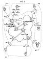
- an OBS-type RC communication network (“Optical Burst Switching") based on a burst mode optical packet switching, comprising input and output nodes NES1 to NES4 and core nodes NC1 to NC3 and connected to client equipments EQ1 to EQ7 such as local network routers.
- the EQ1 and EQ2 client devices are attached to the NES4 node via IN14 and IN24 input and output interfaces.
- the EQ3 client equipment is attached to the NES1 node via an interface input and output IN31.
- the EQ4 and EQ5 client devices are attached to the NES2 node via IN42 and IN52 input and output interfaces.
- the EQ6 and EQ7 client devices are attached to the NES3 node via IN63 and IN73 input and output interfaces.
- the equipment EQ1, EQ5, EQ6 and EQ7 belong to a first virtual private network VPN1 ("Virtual Private Network" in English) delimited by the communication interfaces IN41, IN52, IN63 and IN73 with respect to the communication network RC.
- the equipment EQ2, EQ3 and EQ4 belong to a second virtual private network VPN2 delimited by the interfaces IN24, IN31 and IN42 with respect to the communication network RC.
- the links between the nodes in the network RC consist essentially of optical fibers supporting WDM ("Wavelength-Division Multiplexing").
- WDM Widelength-Division Multiplexing
- the invention is not limited to the above numbers of nodes and client equipments, to the above numbers of virtual private networks and client equipments by virtual private network and to the illustrated architecture of the RC communication network. .
- the NES1, NES2, NES3 and NES4 input and output nodes are gateways between the client equipment and the RC network and each have interfaces connected to client devices belonging to the same or different networks. virtual VPNs.
- Each input and output node assembles P packets entering the RC network and transmitted by respective equipment in bursts B (bursts in English) transmitted to core nodes and disassemble bursts transmitted by heart nodes the RC network packets out of the network and transmitted to the respective equipment.
- two bursts belonging to the same VPN network can cross the RC network to different "output" nodes
- two bursts belonging to the same VPN network can follow two different paths to arrive at the same "output” node
- two bursts belonging to two different VPN networks can cross the RC network to the same "output” node by taking a same path or two different paths
- two packets coming from the same "input" interface can be intended for a single same "output" node and exit the RC network by two different interfaces.
- a given input and output node of the OBS network comprises the following means.
- the given input and output node comprises means for forming an incoming burst of the RC network from incoming optical packets to be assembled according to an identifier of a VPN virtual network indicating the membership of the client equipment or devices that transmitted the packets from the VPN network, and based on a destination address read in the packets and identifying an output node associated with an identifier of a transfer path between the node given input and output and said output node, recognize the input interface for each packet incoming by the given node and therefore the membership of each packet to a VPN network, and thus associate each formed burst to a VPN virtual network to which it belongs and identify the transfer path to follow for each burst and direct it to a port of output of the given node.
- the given input and output node may further comprise means for calculating possible paths for each pair comprising the given node and an input and output node leaving the packets belonging to each VPN network served by the given node, and possibly reserve the resources for each VPN served by the given node.
- Optical packets transiting in the same VPN virtual private network and traversing as input and output of the RC network of the NES common input and output nodes and thus being able to follow the same transfer path in the RC network are assembled in the node "d".
- the given input and output node comprises means for disassembling the bursts transmitted by a heart node to an input port of the given node into packets transferred to the output interfaces IN of a or multiple VPN virtual networks and recognize the membership of each burst received by the given node to a VPN virtual network; recognize the output interface for each outgoing packet of the given node and thus the membership of the outbound packet to a virtual network VPN; match input and output interfaces to one or more VPNs; and recognize the attachment of the input and output interfaces to the input and output nodes.
- Each core node recognizes the membership of a received burst at a respective VPN virtual network, recognizes the transfer path to be followed in the RC network by the received burst, and provides a transfer of the received burst through an input port. from the heart node to an output port of the heart node directed to the next node following the transfer path.
- the salvo transfers in a heart node are therefore transparent.
- Each node NES, NC of the network RC contains or has the means to access a routing table associating pairs of identifier ID_CH main transfer path CH and identifier VPN VPN ID_VPN respectively to port identifiers d ID_PE input and ID_PS output port identifiers of nodes traversed by the transfer path.
- the identifier ID_CH of a transfer path CH of a VPN followed by a burst B transiting through nodes traversed by the transfer path is associated with the ID_PS output port identifiers of the traversed nodes in order to direct in each node traversed the burst to the output port PS connected to the node following the path designated by the identifier ID_CH associated with the identifier ID_VPN.
- the routing table also includes standby output port identifiers associated with standby path identifiers and main path identifiers, as well as other parameters relating to characteristics of the links of the RC network with the node NES, NC.
- the routing table of an NES input and output node further comprises identifiers ID_IN of the input and output interfaces IN of one or more VPNs to which the NES node is connected.
- An identifier ID_IN is used to correctly forward packets to a destination equipment connected to the input and output interface designated by the identifier ID_IN according to the destination address in the packet.
- the communication network RC comprises according to the embodiment illustrated in FIG. figure 2 a PFG management platform connected to the nodes either by specialized signaling links or through links between nodes of the RC network.
- the management platform manages a database of VPN virtual networks in which nodes routing tables are centralized and used to control them.
- the PFG management platform further determines possible paths for each pair of input and output nodes belonging to each VPN, reserves resources for each VPN, configures RC network resources according to the needs of the networks. VPN, and initiates security procedures.
- the database includes ID_VPN identifiers of VPNs, ID_CH identifiers of CH main paths in association with identifiers ID_VPN; backup path identifiers, ID__NES identifiers of NES input and output nodes in association with ID_VPN identifiers and identifiers ID_CH; ID_IN identifiers of the IN and output interfaces attached to each input and output node, as well as other resource parameters of the RC network such as quality of service indicators and bandwidths of links between the nodes of the network. RC network.
- the information stored in the management platform database is regularly updated and used for burst routing.
- the routing tables in the NES and NC nodes are locally synchronized regularly with those of the management platform PFG under the control of this one.
- the contents of the database reflect all the routing tables in the nodes.
- burst B (“burst” in English) comprises three successive fields according to the time t: a label LA ("label” in English) in the header, a packet field CP and an end field CF.
- the LA tag allows the burst to be successfully routed through the OBS type RC network from one NES input and output node to another input and output node.
- the tag contains for the burst routing B an identification field IDL identifying the membership of the burst B to a VPN virtual private network and a path CH followed by the burst B between two input nodes and NES output of the RC network connected to interfaces of the virtual network.
- the identification field IDL includes the identifier ID_VPN of the VPN network to which the burst belongs or the first information on this identifier of the VPN network contributing to identify the VPN network, and an identifier ID_CH the main path CH followed by the burst between the two corresponding input and output nodes of the VPN network in the network RC or second information on this identifier of the main path CH helping to identify the path.
- the length of the label LA expressed in bytes is for example less than 10 bytes.
- the identification field IDL includes the identifier of a second rescue path that can be taken by burst B, for example the identifier of the backup path NES4-NC1-NC3-NC2-NES3 for a burst B1. (LA1, Pa, Pb) in the figure 2 when the NES4-NC1-NC2-NES3 main path becomes unavailable or fails.
- the tag may further include other information such as a VPN provider identifier, a QoS QoS indicator, and the like.
- the packet field CP is intended for the transport of the payload ("pay-load" in English) comprising one or more assembled packets P1 to PK a priori of different lengths, and information on the organization of the packet field and on the routing of each packet included in the packet field.
- the packet field CP comprises a first subfield CPO and K packet subfields CP1 to CPK.
- the first subfield CPO contains information on the payload, for example a start indicator of the packet field CP, the number K of packets carried by the burst B, with 1 ⁇ K, and the total length of the packet field.
- CP for example expressed in bytes.
- the length of the sub-field CPO expressed in bytes is for example 4 bytes.
- the K packet subfields CP1 to CPK are dedicated to packet transport.
- a packet subfield CPk with 1 ⁇ k ⁇ K, includes a packet Pk and in front of it an identifier INk identifying the input and output interface IN by which the packet Pk leaves the communication network RC for enter the associated virtual network VPN and deduced from a destination address in the packet Pk.
- the packet sub-field CPk can include, for example, the identifier of the input and output interface IN by which the packet Pk enters the communication network RC and leaves the associated virtual network VPN.
- the identifier INk preceding the packet Pk is, for example, a prefix part of the IP address of the destination device of the packet Pk or of the input and output node NES through which the packet Pk leaves the communication network RC .
- the identifiers IN1 to INK are used to transfer the packets P1 to PK to the respective input and output interfaces connected to the client equipments EQ to which the packets P1 to PK are intended, after the disassembly of the burst B in the input node and NES output from which packages P1 to PK are output.
- the length of the input and output interface identifiers IN1 to INK is for example 1 or 2 bytes.
- the end field CF delimits the end of the burst B. It may contain a cyclic redundancy check CRC ("Cyclic Redundancy Check" in English) resulting from a function applied to at least the previous CP packet field.
- CRC Cyclic Redundancy Check
- the VPN1 virtual private network transfers Pa and Pb packets from one client equipment EQ1 to two other client equipments EQ6 and EQ7 attached to the same input and output node NES3 connected to the virtual private network VPN1 and retransmitting the packets in the network.
- RC communication network
- the identifier of a transfer path from the node NES4 to the node NES3 for example through the core nodes NC1 and NC2 is already stored in the routing tables of the aforementioned nodes to transfer the packets Pa and Pb from the EQ1 equipment to the EQ6 and EQ7 equipment respectively via the RC network.
- the Pa and Pb packets transmitted by the client equipment EQ1 via the interface IN14 are oriented according to the identifier of the input and output interface IN14 traversed by the packets Pa and Pb and destination addresses read in the Pa and Pb packets.
- the identifier of the IN14 interface makes it possible to deduce first information contributing to identify the virtual network VPN1 as the identifier ID_VPN of the VPN1 network.
- the destination addresses read in the packets make it possible to deduce second information contributing to identify a path NES4-NC1-NC2-NES3 between the nodes NES4 and NES3 as a identifier of path ID-CH linked to identifiers of the nodes NES4 and NES3 input and output or IN63 and IN73 input and output interfaces through which the Pa and Pb packets must exit.
- the packets Pa and Pb are assembled in a packet field CP of a common salvo B1 constructed by the node NES4 according to the Figures 3 and 4 .
- the identifier of the respective "output" interface IN63, IN73 of each packet Pa, Pb is introduced in front of the packet in the packet field CP by the node NES4.
- the node NES4 adds a label LA1 in the header of the burst B1.
- the node NES4 inserts the burst B1 (LA1, Pa, Pb) after an optical signal conversion in the network RC traffic from the node NES4 to the core node NC1.
- the burst B1 (LA1, Pa, Pb) at the core node NC1
- the burst is stored optically, for example in an optical fiber or an optical RAM.
- the burst is stored so that in the heart node NC1 the tag LA1 is read electronically and the routing table is consulted until there is an association of the identifier of the virtual network VPN1 and the identifier of the transfer path NES4 -NC1-NC2-NES3 read in the LA1 tag.
- the next node NC2 which is a core node, performs burst storage B1, an electronic reading of the tag LA1, a lookup of a routing table and a search for a match between the virtual network identifiers and the associated transfer path read in the tag LA1 and the identifier of an output port of the node NC2 directed to the next node NES3, in a manner similar to those in the node NC1, to insert the burst B1 in the traffic of the network RC from the node NC2 to the next node NES3.
- the node NES3 disassembles the burst B1 in the packets Pa and Pb and reads electronically in the burst B1, in particular the identification field IDL of the tag LA1, the number of packets transported and the total length of the packet field CP included in the CPO sub-field of the burst B1, and the identifiers of the input and output interfaces IN63, IN73. These last interface identifiers are found in the routing table of the nodes NES3 in association with the identifier ID_VPN of the network VPN1 read in the label LA1.
- the Pa and Pb packets are respectively transferred to the equipment EQ6 and EQ7 via the interfaces IN63 and IN73 whose identifiers have been found.
- the VPN1 VPN transfers Pa and Pb packets from one client equipment EQ1 to two other client equipments EQ6 and EQ7 attached to a common node NES3 belonging to the network VPN1 as before, and also transfers packets Pc and Pd from the EQ1 client equipment to another EQ5 client equipment attached to NES2 input and output node connected to the VPN1 network and to retransmit packets Pc and Pd.
- the routing table of the node NES4 is consulted to associate the four packets Pa, Pb, Pc and Pd with the identifier of the input and output interface IN14 traversed by these packets and therefore the identifier of the virtual network VPN1, and according to the destination addresses read in the packets for associating the respective input and output interface identifiers IN63 and IN73 with the packets Pa and Pb and the interface identifiers Pc and Pd. respective input and output IN52.
- the NES4 node routing table maps the VPN1 and NES4-NC1-NC2-NES3 identifier association to the identifier of an NES4 node output port to the next NC1 node so that transfer the burst B1 to this output port and insert it into the traffic to the next node NC1.
- the routing table of the NES4 node maps the association of identifiers of the VPN1 network and NES4-NC1-NC3-NES2 path to the identifier of the previous output port or another output port of the node. NES4 directed to the next node NC1 so as to transfer the burst B2 to this output port and insert it into the traffic to the next node NC1.
- the two bursts B1 (LA1, Pa, Pb) and B2 (LA2, Pc, Pd) are optically stored in the core node NC1 which reads the labels LA1 and LA2. If in the routing table of the node NC1 is found the association of the identifier of the virtual network VPN1 and the identifier of the transfer path NES4-NC1-NC2-NES3 read in the label LA1, the burst B1 is directed to an output port of the node NC1 which is connected to the next node NC2 along the transfer path NES4-NC1-NC2-NES3.
- the burst B2 is directed to an output port of the node NC1 which is connected to the next node NC3 along the transfer path NES4-NC1-NC3-NES2.
- next nodes NC2 and NC3 respectively insert the burst B1 in the traffic of the network RC to the next node NES3 following the transfer path NES4-NC1-NC2-NES3 and the burst B2 in the traffic of the network RC to the next node NES2 along the NES4-NC1-NC3-NES2 transfer path, in a manner similar to burst storage, electronic tag readout, routing table lookup, and match lookup between virtual network and read path identifiers read and an output port identifier previously described for burst B1.
- the node NES3 disassembles the burst B1 in the Pa and Pb packets to transfer them respectively to the equipment EQ6 and EQ7 via the interfaces IN63 and IN73 whose identifiers are extracted from the field CP of the burst B1, as previously.
- the node NES2 disassembles the burst B2 in the packets Pc and Pd and reads electronically in the burst B2 the identification field IDL of the tag LA2, the subfield CPO and the interface identifiers IN52 input and output. These last interface identifiers are found in the routing table of the node NES2 in association with the identifier of the network VPN1 extracted from the label LA2.
- the Pc and Pd packets are transferred to the EQ5 equipment via the IN52 interface.
- the input and output node NES4 receives packets Pe and Pf and packets Pg and Ph respectively of customer equipments EQ1 and EQ2 belonging to two different VPN1 and VPN2 virtual private networks, and a single input and output node.
- output NES2 distributes the Pe and Pf packets to an EQ5 recipient client equipment belonging to the VPN1 network and the Pg and Ph packets to an EQ4 recipient client equipment belonging to the VPN2 network.
- the identifier of a transfer path from the node NES4 to the node NES2 for example through the core nodes NC1 and NC3 is already stored in the routing tables of the aforementioned nodes to transfer the data.
- Pe, Pf, Pg and Ph packets of the EQ1 and EQ2 equipment respectively to the EQ5 and EQ4 equipment via the RC network.
- the packets Pe and Pf transmitted by the client equipment EQ1 via the input and output interface IN14 are oriented according to the identifier of the interface IN14 traversed by the packets Pe and Pf which identifies the VPN1 network, and as a function of the destination addresses read in the packets Pe and Pf which identifies an "out" node NES2 and an "output" interface IN52 through which the packets Pe and Pf must exit.
- the packets Pg and Ph transmitted by the client equipment EQ2 via the input and output interface IN24 are oriented according to the identifier of the interface IN24 traversed by the packets Pg and Ph which identifies the VPN2 network, and according to the destination addresses read in the packets Pg and Ph which identifies an "output" node NES2 and an "output" interface IN42 through which the packets Pg and Ph must go out.
- the bursts B3 and B4 have labels LA3 and LA4 respectively including the identifiers of the virtual private networks VPN1 and VPN2 and having in common the identifier of the aforementioned transfer path NES4-NC1-NC3-NES2.
- the NES4 node routing table maps the association of VPN1 and NES4-NC1-NC3-NES2 IDs to the identifier of an output port to the next NC1 node to transfer the burst B3 to this exit port and insert it into the traffic to the node NC1, and map the association of identifiers of the VPN2 network and the NES4-NC1-NC3-NES2 path to the identifier of the previous output port or another output port directed to the next node NC1 so as to transfer the burst B4 to this output port and insert it into the traffic to the node NC1.
- the node NES4 determines the order and times of transfer of the bursts B3 and B4 to avoid collisions in the traffic to the core node NC1.
- next nodes NC1 and NC3 insert the bursts B3 (LA3, Pe, Pf) and B4 (LA4, Pg, Ph) in the traffic of the network RC to the following respective nodes NC3 and NES2 according to the transfer path NES4-NC1- NC3-NES2 in a manner similar to burst storage, electronic tag reading, routing table lookup, and match lookup between virtual network identifiers and read forward path and port identifier previously described for burst B1 in core nodes NC1 and NC2.
- the node NES2 disassembles the burst B3 in the packets Pe and Pf and electronically reads in the burst B3 the identification field IDL of the label LA3, the subfield CPO and the identifier of interface of input and output IN52 in front of the Pe and Pf packets in order to find this interface identifier in the routing table of the NES2 node in association with the identifier of the VPN1 network extracted from the label LA3 and to transfer the packets Pe and Pf to the equipment EQ5 via the IN52 interface.
- the NES2 node disassembles the burst B4 in the packets Pg and Ph and reads electronically in the burst B4 the identification field IDL of the tag LA4, the subfield CPO and the identifier input and output interface IN42 in front of the packets Pg and Ph in order to find this interface identifier in the routing table of the node NES2 in association with the identifier of the network VPN2 extracted from the label LA4 and transfer the Pg and Ph packets to the EQ4 equipment via the IN42 interface.
- a NES input and output node receiving P packets from a virtual network introduces information that helps identify the path to be followed by the burst assembling received packets, such as the ID_IN of an input and output interface IN having to enter a packet P to be inserted into the burst B, the identifier ID_IN of an input and output interface IN to output a packet P extracted from the burst B, the address of an input node and output signal serving the input and output interface IN to input a packet P to be inserted into the burst B, or the address of an input and output node serving the input and output interface IN to output a packet P extracted from salve B.
- the routing tables in nodes NES and NC and d the PFG management platform are modified accordingly.
- control of the routing tables in the nodes NES and NC of the network RC is no longer centralized in a management platform PFG, but is distributed in the nodes NES and NC according to a control plane of the nodes .
- the invention described here relates to a burst assembling packets, a method of assembling packets to be transmitted in a virtual network supported by a communication network, a node such as NES4 node through which Pa and Pb packets to be transmitted in a virtual network VPN1 are able to enter an RC communication network supporting the virtual network, a core node such as the node NC1, NC2 by which Pa and Pb packets to be transmitted in a virtual network VPN1 are able to transit in a network RC communication supporting the VPN1 virtual network, and a node such as the node NES3 by which Pa and Pb packets to be transmitted in a virtual network VPN1 are able to exit a communication network RC supporting the virtual network.
- the steps of the method of the invention are determined by computer program instructions incorporated respectively in said nodes.
- the programs include program instructions which, when said programs are executed in said nodes whose operation is then controlled by the execution of the programs, carry out the steps of the method according to the invention.
- the invention also applies to computer programs, in particular computer programs recorded on or in one or more computer-readable recording media and any data processing device, adapted to implement the invention.
- These programs can use any programming language, and be in the form of source code, object code, or intermediate code between source code and object code such as in a partially compiled form, or in any another form desirable for implementing the method according to the invention.
- a recording medium can be any entity or device capable of storing a program.
- the medium may comprise storage means on which the computer program according to the invention is recorded, such as a ROM, for example a CD ROM or a microelectronic circuit ROM, or a USB key, or magnetic recording means, for example a diskette (floppy disc) or a hard disk.
- the recording medium may be a transmissible medium such as an electrical or optical signal, which may be conveyed via an electrical or optical cable, by radio or by other means.
- the program according to the invention can in particular be downloaded to an Internet type network.
- the recording medium may be an integrated circuit in which the program is incorporated, the circuit being adapted to execute or to be used in the execution of the method according to the invention.
Landscapes
- Engineering & Computer Science (AREA)
- Computer Networks & Wireless Communication (AREA)
- Signal Processing (AREA)
- Computer Security & Cryptography (AREA)
- Data Exchanges In Wide-Area Networks (AREA)
Claims (16)
- Stoß (B1), der optische Pakete (Pa, Pb) vereint, die in einem virtuellen Netz (VPN1) zu übertragen sind, das von einem Kommunikationsnetz (RC) vom Typ mit Wellenlängenmultiplex unterstützt wird, dadurch gekennzeichnet, dass er ein Etikett (LA1) umfasst, das Paketfeld (CP) vorangestellt ist, das optische Pakete (Pa, Pb) vereint, die von dem virtuellen Netz kommen und geeignet sind, in das Kommunikationsnetz durch einen ersten Knoten (NES4) einzutreten und aus dem Kommunikationsnetz durch einen zweiten Knoten (NES3) auszutreten, wobei das Etikett erste Informationen (ID_VPN) einschließt, die dazu beitragen, das virtuelle Netz zu identifizieren, und zweite Informationen (ID_CH), die dazu beitragen, einen Weg (NES4-NC1-NC2-NES3) zwischen dem ersten und dem zweiten Konten zu identifizieren, wobei die ersten und zweiten Informationen während des Durchlaufens des Stoßes zwischen dem ersten und dem zweiten Knoten des Kommunikationsnetzes unverändert sind.
- Stoß nach Anspruch 1, bei dem das Paketfeld ein erstes Unterfeld (CPO) umfasst, das die Anzahl von optischen Paketen, die in dem Paketfeld (CP) eingeschlossen sind, und die Länge des Paketfeldes einschließt.
- Stoß nach Anspruch 2, bei dem jedem optischen Paket (Pk) in dem Paketfeld (CP) ein Identifikator (INk) vorangestellt ist, der eine Schnittstelle identifiziert, durch die das Paket aus dem Kommunikationsnetz (RC) austritt, und eine Bestimmungsadresse in dem Paket ableitet.
- Stoß nach einem der Ansprüche 1 bis 3, bei dem das Etikett einen Identifikator eines zweiten Weges zwischen dem ersten und dem zweiten Knoten einschließt.
- Verfahren zum Vereinen von optischen Paketen, die in einem virtuellen Netz (VPN1) zu übertragen sind, das von einem Kommunikationsnetz (RC) vom Typ mit Wellenlängenmultiplex unterstützt wird, dadurch gekennzeichnet, dass es in einem ersten Knoten (NES4), durch den optische Pakete (Pa, Pb) in das Kommunikationsnetz eintreten können, eine Vereinigung von optischen Paketen (Pa, Pb) umfasst, die von dem virtuellen Netz in einem Paketfeld (CP) stammen, und eine Bildung eines Stoßes (B1), umfassend das Paketfeld (CP) und ein Etikett (LA1), das dem Paketfeld (CP) vorangestellt ist und erste Informationen (ID_VPN), die dazu beitragen, das virtuelle Netz zu identifizieren, und zweite Informationen (ID_CH) einschließt, die dazu beitragen, einen Weg (NES4-NC1-NC2-NES3) zwischen dem ersten Knoten und einem zweiten Knoten (NES3) zu identifizieren, durch den die Pakete (Pa, Pb) aus dem Kommunikationsnetz austreten können, wobei die ersten und zweiten Informationen während des Durchlaufens des Stoßes zwischen dem ersten und dem zweiten Knoten des Kommunikationsnetzes unverändert sind.
- Verfahren nach Anspruch 5, bei dem die ersten Informationen (ID_VPN), die dazu beitragen, das virtuelle Netz für jedes optische Paket (Pa, Pb), das von dem ersten Knoten (NES4) empfangen wird, zu identifizieren, vom Durchlaufen des Pakets durch eine jeweilige Schnittstelle (IN14), die mit dem ersten Knoten (NES4) verbunden ist, abgeleitet werden.
- Verfahren nach Anspruch 5, bei dem die zweiten Informationen (ID_CH), die dazu beitragen, einen Weg (NES4-NC1-NC2-NES3) zwischen dem ersten und dem zweiten Knoten für jedes Paket (Pa, Pb), das von dem ersten Knoten (NES4) empfangen wird, zu identifizieren, von einer Bestimmungsadresse, die in dem Paket gelesen wird, abgeleitet werden.
- Verfahren nach Anspruch 5, umfassend in einem zentralen Knoten (NC1, NC2) des Kommunikationsnetzes (RC), der sich auf dem Weg (NES4-NC1-NC2-NES3) zwischen dem ersten und dem zweiten Knoten (NES4, NES3) befindet, eine optische Speicherung des Stoßes (B1), eine Suche eines Austrittspunktes, der zum nächsten Knoten (NC2, NES3) entlang des Weges in Übereinstimmung mit den ersten und zweiten Informationen (ID_VPN, ID_CH), die in dem Etikett (LA1) gelesen werden, gerichtet ist, und eine Weiterleitung des Stoßes zu dem Austrittspunkt, um ihn in den Verkehrsfluss zum nächsten Knoten einzufügen.
- Verfahren zum Trennen von Paketen, die in einem virtuellen Netz (VPN1) zu übertragen sind, das von einem Kommunikationsnetz (RC) vom Typ mit Wellenlängenmultiplex unterstützt wird, dadurch gekennzeichnet, dass in einem zweiten Knoten (NES3), durch den optische Pakete (Pa, Pb) aus dem Kommunikationsnetz austreten können, die von dem virtuellen Netz entlang eines Weges (NES4-NC1-NC2-NES3) von einem ersten Knoten (NES4), durch den die optischen Pakete (Pa, Pb) in das Kommunikationsnetz eintreten können, kommen, das Verfahren eine Trennung eines Stoßes (B1), der von dem Kommunikationsnetz (RC) in Paketen (Pa, Pb), die von dem virtuellen Netz kommen, und ein Etikett (LA1) umfasst, das den Paketen vorangestellt ist und erste Informationen (ID_VPN), die dazu beitragen, das virtuelle Netz zu identifizieren, und zweite Informationen (ID_CH) umfasst, die dazu beitragen, den Weg (NES4-NC1-NC2-NES3) zu identifizieren, wobei die ersten und die zweiten Informationen während des Durchlaufens des Stoßes zwischen dem ersten und dem zweiten Knoten des Kommunikationsnetzes unverändert ist.
- Verfahren nach Anspruch 9, umfassend in einem ersten Knoten (NES4) für jedes in dem Stoß (B1) zu vereinende optische Paket (Pa, Pb) eine Einführung eines Identifikators (INk) vor dem optischen Paket (Pk), der eine Schnittstelle identifiziert, durch die das optische Paket aus dem Kommunikationsnetz (RC) austreten kann und von einer Bestimmungsadresse in dem Paket abgleitet wird, und in einem zweiten Knoten (NES3) eine Suche nach Identifikatoren der Schnittstellen (IN63, IN73), die in dem Stoß in Verbindung mit dem Identifikator des virtuellen Netzes (VPN1) gelesen wurden, um die Pakete über die Schnittstellen weiterzuleiten.
- Knoten (NES4), durch den in einem virtuellen Netz (VPN1) zu übertragende Pakete in ein Kommunikationsnetz (RC) vom Typ mit Wellenlängenmultiplex, das das virtuelle Netz unterstützt, eintreten können, dadurch gekennzeichnet, dass er optische Pakete (Pa, Pb), die von dem virtuellen Netz kommen, in einem Paketfeld (CP) vereinen und einen Stoß (B1) bilden kann, umfassend das Paketfeld (CP) und ein Etikett (LA1), das dem Paketfeld (CP) vorangestellt ist und erste Informationen (ID_VPN), die dazu beitragen, das virtuelle Netz zu identifizieren, und zweite Informationen (ID_CH) einschließt, die dazu beitragen, einen Weg (NES4-NC1-NC2-NES3) zwischen dem ersten Knoten und einem zweiten Knoten (NES3) zu identifizieren, durch den die optischen Pakete (Pa, Pb) aus dem Kommunikationsnetz austreten können, wobei die ersten und zweiten Informationen während des Durchlaufens des Stoßes zwischen dem ersten und dem zweiten Knoten des Kommunikationsnetzes unverändert sind.
- Zentraler Knoten (NC1, NC2), durch den in einem virtuellen Netz (VPN1) zu übertragende optische Pakete in ein Kommunikationsnetz (RC) vom Typ mit Wellenlängenmultiplex, das das virtuelle Netz unterstützt, übergehen können, dadurch gekennzeichnet, dass er einen Stoß (B1) optisch speichern kann, umfassend ein Paketfeld (CP), das optische Pakete (Pa, Pb) vereint, die von dem virtuellen Netz kommen, und ein Etikett (LA1), das dem Paketfeld (CP) vorangestellt ist und erste Informationen (ID_VPN), die dazu beitragen, das virtuelle Netz zu identifizieren, und zweite Informationen (ID_CH) einschließt, die dazu beitragen, einen Weg (NES4-NC1-NC2-NES3) zwischen einem ersten Knoten, durch den die Pakete (Pa, Pb) in das Kommunikationsnetz eintreten können, und einem zweiten Knoten (NES3) zu identifizieren, durch den die Pakete (Pa, Pb) aus dem Kommunikationsnetz austreten können, wobei die ersten und die zweiten Informationen während des Durchlaufens des Stoßes zwischen dem ersten und dem zweiten Knoten des Kommunikationsnetzes unverändert sind, einen Austrittspunkt suchen kann, der zu dem nächsten Knoten (NC2, NES3) entlang des Weges in Übereinstimmung mit den ersten und zweiten Informationen, die in dem Etikett (LA1) gelesen werden, gerichtet ist, und den Stoß zu dem Austrittspunkt weiterleiten kann, um ihn in den Verkehrsfluss zum nächsten Knoten einzusetzen.
- Knoten (NES3), durch den in einem virtuellen Netz (VPN1) zu übertragende optische Pakete aus einem Kommunikationsnetz (RC) vom Typ mit Wellenlängenmultiplex austreten können, dadurch gekennzeichnet, dass er einen Stoß (B1) in optische Pakete (Pa, PB), die von dem virtuellen Netz kommen, trennen kann, umfassend ein Paketfeld (CP), das die optischen Pakete (Pa, Pb) vereint, vor denen jeweils (Pk) ein Identifikator (INk) eingeführt wird, der eine Schnittstelle identifiziert, durch die das optische Paket aus dem Kommunikationsnetz (RC) austreten kann, und ein Etikett (LA1), das dem Paketfeld (CP) vorangestellt ist und erste Informationen (ID_VPN), die dazu beitragen, das virtuelle Netz zu identifizieren, und zweite Informationen (ID_CH) einschließt, die dazu beitragen, einen Weg (NES4-NC1-NC2-NES3) zwischen einem ersten Knoten, durch den die optischen Pakete (Pa, Pb) in das Kommunikationsnetz eintreten können, und dem zweiten Knoten (NES3) zu identifizieren, und Identifikatoren der Schnittstellen (IN63, IN73) sucht, die in dem Stoß in Verbindung mit den ersten Informationen gelesen wurden, um die optischen Pakete über die Schnittstellen weiterzuleiten.
- Computerprogramm, umfassend Befehle für den Einsatz in einem Knoten (NES4) nach Anspruch 11, wenn das Programm in dem Knoten ausgeführt wird.
- Computerprogramm, umfassend Befehle für den Einsatz in einem zentralen Knoten (NC1, NC2) nach Anspruch 12, wenn das Programm in dem Knoten ausgeführt wird.
- Computerprogramm, umfassend Befehle für den Einsatz in einem Knoten (NES3) nach Anspruch 13, wenn das Programm in dem Knoten ausgeführt wird.
Applications Claiming Priority (2)
| Application Number | Priority Date | Filing Date | Title |
|---|---|---|---|
| FR0752782 | 2007-01-19 | ||
| PCT/FR2008/050070 WO2008107590A1 (fr) | 2007-01-19 | 2008-01-15 | Assemblage de paquets dans un reseau de communication supportant des reseaux virtuels |
Publications (3)
| Publication Number | Publication Date |
|---|---|
| EP2109964A1 EP2109964A1 (de) | 2009-10-21 |
| EP2109964B1 EP2109964B1 (de) | 2013-05-15 |
| EP2109964B9 true EP2109964B9 (de) | 2013-10-02 |
Family
ID=38521017
Family Applications (1)
| Application Number | Title | Priority Date | Filing Date |
|---|---|---|---|
| EP08761941.7A Active EP2109964B9 (de) | 2007-01-19 | 2008-01-15 | Paketerstellung in einem kommunikationsnetzwerk mit unterstützung virtueller netzwerke |
Country Status (3)
| Country | Link |
|---|---|
| US (1) | US8155149B2 (de) |
| EP (1) | EP2109964B9 (de) |
| WO (1) | WO2008107590A1 (de) |
Families Citing this family (2)
| Publication number | Priority date | Publication date | Assignee | Title |
|---|---|---|---|---|
| US9042741B2 (en) * | 2011-03-15 | 2015-05-26 | At&T Intellectual Property I, L.P. | System and method for blind frequency recovery |
| CN108600106B (zh) * | 2018-04-28 | 2019-06-14 | 北京邮电大学 | 一种低时延的数据交换装置及方法 |
Family Cites Families (4)
| Publication number | Priority date | Publication date | Assignee | Title |
|---|---|---|---|---|
| JP4099930B2 (ja) * | 2000-06-02 | 2008-06-11 | 株式会社日立製作所 | ルータ装置及びvpn識別情報の設定方法 |
| JP3654168B2 (ja) * | 2000-09-28 | 2005-06-02 | 日本電気株式会社 | インタフェース識別装置、インタフェース識別方法および、mpls−vpnサービスネットワーク |
| US7477844B2 (en) * | 2004-12-17 | 2009-01-13 | Fujitsu Limited | Method and system for utilizing virtual local access network addressing in optical networks |
| US7773516B2 (en) * | 2006-11-16 | 2010-08-10 | Breakingpoint Systems, Inc. | Focused function network processor |
-
2008
- 2008-01-15 EP EP08761941.7A patent/EP2109964B9/de active Active
- 2008-01-15 US US12/523,544 patent/US8155149B2/en active Active
- 2008-01-15 WO PCT/FR2008/050070 patent/WO2008107590A1/fr not_active Ceased
Also Published As
| Publication number | Publication date |
|---|---|
| EP2109964A1 (de) | 2009-10-21 |
| US8155149B2 (en) | 2012-04-10 |
| EP2109964B1 (de) | 2013-05-15 |
| US20100118891A1 (en) | 2010-05-13 |
| WO2008107590A1 (fr) | 2008-09-12 |
Similar Documents
| Publication | Publication Date | Title |
|---|---|---|
| US6598034B1 (en) | Rule based IP data processing | |
| Qiao et al. | Choices, features and issues in optical burst switching | |
| EP1491007B1 (de) | Label switching in fibre channel netzen | |
| JP3507438B2 (ja) | 光タグスイッチングを使用した高スループットで低レイテンシの次世代インターネットネットワーク | |
| US9967638B2 (en) | Optical switching | |
| US9929947B1 (en) | Transmitting packet label contexts within computer networks | |
| US20020165978A1 (en) | Multi-service optical infiniband router | |
| US9716563B2 (en) | Method and apparatus for improving connectivity between optical devices using software defined networking | |
| FR2811179A1 (fr) | Procede de routage de trame ip entre les usagers d'un reseau a graphe variable | |
| EP1575240B1 (de) | Vorrichtung und Verfahren zur Bearbeitung von Rahmen mit multiprotokollverwendungsfeldern für ein Kommunikationsnetzwerk | |
| EP2109964B1 (de) | Paketerstellung in einem kommunikationsnetzwerk mit unterstützung virtueller netzwerke | |
| WO2023156580A1 (fr) | Procédés et dispositifs de traitement de données descendantes pour réseaux optique passifs en cascade | |
| EP1575211A2 (de) | Multicast-Übertragungsverfahren durch das Verringern eines verbundenen Zählers | |
| EP2549773B1 (de) | Vorrichtung und Verfahren zum Vermischen von mit einer Wellenlänge assoziierten optischen Komponenten zu einer gemischten optischen Komponente | |
| Yoo | Choices, features and issues in optical burst switching | |
| EP1355453A1 (de) | Anlage zur zentralisierten Schaltung und Leitweglenkung | |
| US20090232150A1 (en) | Service edge platform architecture for a multi-service access network | |
| JP5853758B2 (ja) | 通信装置及び帯域制御方法 | |
| Düser et al. | Distributed router architecture for packet-routed optical networks | |
| WO2023156579A1 (fr) | Procédés et dispositifs de traitement de données montantes pour réseaux optiques passifs en cascade | |
| Suryaputra et al. | Simple Wavelength Assignment Protocol | |
| Valcarenghi | Survivable IP-over-WDM networks | |
| Louridas | Simulation based modeling of optical burst switching networks | |
| Ovadia et al. | GMPLS-Based Photonic Burst Switching (PBS) Architecture for Optical Networks | |
| Sohraby et al. | Heterogeneous traffic transport over optical networks |
Legal Events
| Date | Code | Title | Description |
|---|---|---|---|
| PUAI | Public reference made under article 153(3) epc to a published international application that has entered the european phase |
Free format text: ORIGINAL CODE: 0009012 |
|
| 17P | Request for examination filed |
Effective date: 20090630 |
|
| AK | Designated contracting states |
Kind code of ref document: A1 Designated state(s): AT BE BG CH CY CZ DE DK EE ES FI FR GB GR HR HU IE IS IT LI LT LU LV MC MT NL NO PL PT RO SE SI SK TR |
|
| 17Q | First examination report despatched |
Effective date: 20100224 |
|
| DAX | Request for extension of the european patent (deleted) | ||
| GRAP | Despatch of communication of intention to grant a patent |
Free format text: ORIGINAL CODE: EPIDOSNIGR1 |
|
| RAP1 | Party data changed (applicant data changed or rights of an application transferred) |
Owner name: FRANCE TELECOM |
|
| GRAS | Grant fee paid |
Free format text: ORIGINAL CODE: EPIDOSNIGR3 |
|
| REG | Reference to a national code |
Ref country code: DE Ref legal event code: R079 Ref document number: 602008024593 Country of ref document: DE Free format text: PREVIOUS MAIN CLASS: H04L0012460000 Ipc: H04L0012715000 |
|
| GRAA | (expected) grant |
Free format text: ORIGINAL CODE: 0009210 |
|
| AK | Designated contracting states |
Kind code of ref document: B1 Designated state(s): AT BE BG CH CY CZ DE DK EE ES FI FR GB GR HR HU IE IS IT LI LT LU LV MC MT NL NO PL PT RO SE SI SK TR |
|
| REG | Reference to a national code |
Ref country code: GB Ref legal event code: FG4D Free format text: NOT ENGLISH Ref country code: CH Ref legal event code: EP |
|
| RIC1 | Information provided on ipc code assigned before grant |
Ipc: H04L 12/715 20130101AFI20130409BHEP Ipc: H04L 12/721 20130101ALI20130409BHEP Ipc: H04L 12/46 20060101ALI20130409BHEP |
|
| REG | Reference to a national code |
Ref country code: AT Ref legal event code: REF Ref document number: 612598 Country of ref document: AT Kind code of ref document: T Effective date: 20130615 |
|
| REG | Reference to a national code |
Ref country code: IE Ref legal event code: FG4D Free format text: LANGUAGE OF EP DOCUMENT: FRENCH |
|
| REG | Reference to a national code |
Ref country code: DE Ref legal event code: R096 Ref document number: 602008024593 Country of ref document: DE Effective date: 20130711 |
|
| GRAT | Correction requested after decision to grant or after decision to maintain patent in amended form |
Free format text: ORIGINAL CODE: EPIDOSNCDEC |
|
| REG | Reference to a national code |
Ref country code: CH Ref legal event code: PUE Owner name: ORANGE, FR Free format text: FORMER OWNER: FRANCE TELECOM, FR |
|
| RAP2 | Party data changed (patent owner data changed or rights of a patent transferred) |
Owner name: ORANGE |
|
| REG | Reference to a national code |
Ref country code: AT Ref legal event code: MK05 Ref document number: 612598 Country of ref document: AT Kind code of ref document: T Effective date: 20130515 |
|
| REG | Reference to a national code |
Ref country code: LT Ref legal event code: MG4D |
|
| REG | Reference to a national code |
Ref country code: NL Ref legal event code: VDEP Effective date: 20130515 |
|
| PG25 | Lapsed in a contracting state [announced via postgrant information from national office to epo] |
Ref country code: IS Free format text: LAPSE BECAUSE OF FAILURE TO SUBMIT A TRANSLATION OF THE DESCRIPTION OR TO PAY THE FEE WITHIN THE PRESCRIBED TIME-LIMIT Effective date: 20130915 Ref country code: AT Free format text: LAPSE BECAUSE OF FAILURE TO SUBMIT A TRANSLATION OF THE DESCRIPTION OR TO PAY THE FEE WITHIN THE PRESCRIBED TIME-LIMIT Effective date: 20130515 Ref country code: SI Free format text: LAPSE BECAUSE OF FAILURE TO SUBMIT A TRANSLATION OF THE DESCRIPTION OR TO PAY THE FEE WITHIN THE PRESCRIBED TIME-LIMIT Effective date: 20130515 Ref country code: SE Free format text: LAPSE BECAUSE OF FAILURE TO SUBMIT A TRANSLATION OF THE DESCRIPTION OR TO PAY THE FEE WITHIN THE PRESCRIBED TIME-LIMIT Effective date: 20130515 Ref country code: LT Free format text: LAPSE BECAUSE OF FAILURE TO SUBMIT A TRANSLATION OF THE DESCRIPTION OR TO PAY THE FEE WITHIN THE PRESCRIBED TIME-LIMIT Effective date: 20130515 Ref country code: FI Free format text: LAPSE BECAUSE OF FAILURE TO SUBMIT A TRANSLATION OF THE DESCRIPTION OR TO PAY THE FEE WITHIN THE PRESCRIBED TIME-LIMIT Effective date: 20130515 Ref country code: ES Free format text: LAPSE BECAUSE OF FAILURE TO SUBMIT A TRANSLATION OF THE DESCRIPTION OR TO PAY THE FEE WITHIN THE PRESCRIBED TIME-LIMIT Effective date: 20130826 Ref country code: PT Free format text: LAPSE BECAUSE OF FAILURE TO SUBMIT A TRANSLATION OF THE DESCRIPTION OR TO PAY THE FEE WITHIN THE PRESCRIBED TIME-LIMIT Effective date: 20130916 Ref country code: GR Free format text: LAPSE BECAUSE OF FAILURE TO SUBMIT A TRANSLATION OF THE DESCRIPTION OR TO PAY THE FEE WITHIN THE PRESCRIBED TIME-LIMIT Effective date: 20130816 Ref country code: NO Free format text: LAPSE BECAUSE OF FAILURE TO SUBMIT A TRANSLATION OF THE DESCRIPTION OR TO PAY THE FEE WITHIN THE PRESCRIBED TIME-LIMIT Effective date: 20130815 |
|
| PG25 | Lapsed in a contracting state [announced via postgrant information from national office to epo] |
Ref country code: BG Free format text: LAPSE BECAUSE OF FAILURE TO SUBMIT A TRANSLATION OF THE DESCRIPTION OR TO PAY THE FEE WITHIN THE PRESCRIBED TIME-LIMIT Effective date: 20130815 Ref country code: HR Free format text: LAPSE BECAUSE OF FAILURE TO SUBMIT A TRANSLATION OF THE DESCRIPTION OR TO PAY THE FEE WITHIN THE PRESCRIBED TIME-LIMIT Effective date: 20130515 Ref country code: PL Free format text: LAPSE BECAUSE OF FAILURE TO SUBMIT A TRANSLATION OF THE DESCRIPTION OR TO PAY THE FEE WITHIN THE PRESCRIBED TIME-LIMIT Effective date: 20130515 |
|
| PG25 | Lapsed in a contracting state [announced via postgrant information from national office to epo] |
Ref country code: LV Free format text: LAPSE BECAUSE OF FAILURE TO SUBMIT A TRANSLATION OF THE DESCRIPTION OR TO PAY THE FEE WITHIN THE PRESCRIBED TIME-LIMIT Effective date: 20130515 |
|
| PG25 | Lapsed in a contracting state [announced via postgrant information from national office to epo] |
Ref country code: CZ Free format text: LAPSE BECAUSE OF FAILURE TO SUBMIT A TRANSLATION OF THE DESCRIPTION OR TO PAY THE FEE WITHIN THE PRESCRIBED TIME-LIMIT Effective date: 20130515 Ref country code: DK Free format text: LAPSE BECAUSE OF FAILURE TO SUBMIT A TRANSLATION OF THE DESCRIPTION OR TO PAY THE FEE WITHIN THE PRESCRIBED TIME-LIMIT Effective date: 20130515 Ref country code: SK Free format text: LAPSE BECAUSE OF FAILURE TO SUBMIT A TRANSLATION OF THE DESCRIPTION OR TO PAY THE FEE WITHIN THE PRESCRIBED TIME-LIMIT Effective date: 20130515 Ref country code: EE Free format text: LAPSE BECAUSE OF FAILURE TO SUBMIT A TRANSLATION OF THE DESCRIPTION OR TO PAY THE FEE WITHIN THE PRESCRIBED TIME-LIMIT Effective date: 20130515 |
|
| PG25 | Lapsed in a contracting state [announced via postgrant information from national office to epo] |
Ref country code: NL Free format text: LAPSE BECAUSE OF FAILURE TO SUBMIT A TRANSLATION OF THE DESCRIPTION OR TO PAY THE FEE WITHIN THE PRESCRIBED TIME-LIMIT Effective date: 20130515 Ref country code: RO Free format text: LAPSE BECAUSE OF FAILURE TO SUBMIT A TRANSLATION OF THE DESCRIPTION OR TO PAY THE FEE WITHIN THE PRESCRIBED TIME-LIMIT Effective date: 20130515 Ref country code: IT Free format text: LAPSE BECAUSE OF FAILURE TO SUBMIT A TRANSLATION OF THE DESCRIPTION OR TO PAY THE FEE WITHIN THE PRESCRIBED TIME-LIMIT Effective date: 20130515 |
|
| PLBE | No opposition filed within time limit |
Free format text: ORIGINAL CODE: 0009261 |
|
| STAA | Information on the status of an ep patent application or granted ep patent |
Free format text: STATUS: NO OPPOSITION FILED WITHIN TIME LIMIT |
|
| 26N | No opposition filed |
Effective date: 20140218 |
|
| REG | Reference to a national code |
Ref country code: DE Ref legal event code: R097 Ref document number: 602008024593 Country of ref document: DE Effective date: 20140218 |
|
| BERE | Be: lapsed |
Owner name: FRANCE TELECOM Effective date: 20140131 |
|
| PG25 | Lapsed in a contracting state [announced via postgrant information from national office to epo] |
Ref country code: MC Free format text: LAPSE BECAUSE OF FAILURE TO SUBMIT A TRANSLATION OF THE DESCRIPTION OR TO PAY THE FEE WITHIN THE PRESCRIBED TIME-LIMIT Effective date: 20130515 Ref country code: LU Free format text: LAPSE BECAUSE OF FAILURE TO SUBMIT A TRANSLATION OF THE DESCRIPTION OR TO PAY THE FEE WITHIN THE PRESCRIBED TIME-LIMIT Effective date: 20140115 |
|
| REG | Reference to a national code |
Ref country code: CH Ref legal event code: PL |
|
| PG25 | Lapsed in a contracting state [announced via postgrant information from national office to epo] |
Ref country code: CH Free format text: LAPSE BECAUSE OF NON-PAYMENT OF DUE FEES Effective date: 20140131 Ref country code: LI Free format text: LAPSE BECAUSE OF NON-PAYMENT OF DUE FEES Effective date: 20140131 |
|
| REG | Reference to a national code |
Ref country code: IE Ref legal event code: MM4A |
|
| PG25 | Lapsed in a contracting state [announced via postgrant information from national office to epo] |
Ref country code: IE Free format text: LAPSE BECAUSE OF NON-PAYMENT OF DUE FEES Effective date: 20140115 Ref country code: BE Free format text: LAPSE BECAUSE OF NON-PAYMENT OF DUE FEES Effective date: 20140131 |
|
| REG | Reference to a national code |
Ref country code: FR Ref legal event code: PLFP Year of fee payment: 9 |
|
| PG25 | Lapsed in a contracting state [announced via postgrant information from national office to epo] |
Ref country code: MT Free format text: LAPSE BECAUSE OF FAILURE TO SUBMIT A TRANSLATION OF THE DESCRIPTION OR TO PAY THE FEE WITHIN THE PRESCRIBED TIME-LIMIT Effective date: 20130515 |
|
| PG25 | Lapsed in a contracting state [announced via postgrant information from national office to epo] |
Ref country code: CY Free format text: LAPSE BECAUSE OF FAILURE TO SUBMIT A TRANSLATION OF THE DESCRIPTION OR TO PAY THE FEE WITHIN THE PRESCRIBED TIME-LIMIT Effective date: 20130515 |
|
| PG25 | Lapsed in a contracting state [announced via postgrant information from national office to epo] |
Ref country code: TR Free format text: LAPSE BECAUSE OF FAILURE TO SUBMIT A TRANSLATION OF THE DESCRIPTION OR TO PAY THE FEE WITHIN THE PRESCRIBED TIME-LIMIT Effective date: 20130515 Ref country code: HU Free format text: LAPSE BECAUSE OF FAILURE TO SUBMIT A TRANSLATION OF THE DESCRIPTION OR TO PAY THE FEE WITHIN THE PRESCRIBED TIME-LIMIT; INVALID AB INITIO Effective date: 20080115 |
|
| REG | Reference to a national code |
Ref country code: FR Ref legal event code: PLFP Year of fee payment: 10 |
|
| REG | Reference to a national code |
Ref country code: DE Ref legal event code: R081 Ref document number: 602008024593 Country of ref document: DE Owner name: TRANSPACIFIC IP GROUP LTD., GEORGE TOWN, KY Free format text: FORMER OWNER: FRANCE TELECOM, PARIS, FR |
|
| REG | Reference to a national code |
Ref country code: GB Ref legal event code: 732E Free format text: REGISTERED BETWEEN 20180222 AND 20180228 |
|
| REG | Reference to a national code |
Ref country code: FR Ref legal event code: PLFP Year of fee payment: 11 |
|
| REG | Reference to a national code |
Ref country code: FR Ref legal event code: TP Owner name: TRANSPACIFIC IP GROUP LIMITED, KY Effective date: 20180613 |
|
| REG | Reference to a national code |
Ref country code: DE Ref legal event code: R079 Ref document number: 602008024593 Country of ref document: DE Free format text: PREVIOUS MAIN CLASS: H04L0012715000 Ipc: H04L0045640000 |
|
| PGFP | Annual fee paid to national office [announced via postgrant information from national office to epo] |
Ref country code: GB Payment date: 20241226 Year of fee payment: 18 |
|
| PGFP | Annual fee paid to national office [announced via postgrant information from national office to epo] |
Ref country code: FR Payment date: 20241227 Year of fee payment: 18 |
|
| PGFP | Annual fee paid to national office [announced via postgrant information from national office to epo] |
Ref country code: DE Payment date: 20241231 Year of fee payment: 18 |