EP2109745B1 - Refrigerator - Google Patents
Refrigerator Download PDFInfo
- Publication number
- EP2109745B1 EP2109745B1 EP07768696.2A EP07768696A EP2109745B1 EP 2109745 B1 EP2109745 B1 EP 2109745B1 EP 07768696 A EP07768696 A EP 07768696A EP 2109745 B1 EP2109745 B1 EP 2109745B1
- Authority
- EP
- European Patent Office
- Prior art keywords
- icemaker
- door
- lever
- case
- refrigerator according
- Prior art date
- Legal status (The legal status is an assumption and is not a legal conclusion. Google has not performed a legal analysis and makes no representation as to the accuracy of the status listed.)
- Active
Links
- 238000005057 refrigeration Methods 0.000 claims description 25
- 238000007599 discharging Methods 0.000 claims description 2
- 230000004888 barrier function Effects 0.000 description 3
- 230000000994 depressogenic effect Effects 0.000 description 2
- 238000007792 addition Methods 0.000 description 1
- 238000005452 bending Methods 0.000 description 1
- 238000001816 cooling Methods 0.000 description 1
- 230000008878 coupling Effects 0.000 description 1
- 238000010168 coupling process Methods 0.000 description 1
- 238000005859 coupling reaction Methods 0.000 description 1
- 230000003247 decreasing effect Effects 0.000 description 1
- 238000012217 deletion Methods 0.000 description 1
- 230000037430 deletion Effects 0.000 description 1
- 230000000694 effects Effects 0.000 description 1
- 238000007710 freezing Methods 0.000 description 1
- 230000008014 freezing Effects 0.000 description 1
- 238000003780 insertion Methods 0.000 description 1
- 230000037431 insertion Effects 0.000 description 1
- 239000011810 insulating material Substances 0.000 description 1
- 230000004048 modification Effects 0.000 description 1
- 238000012986 modification Methods 0.000 description 1
- 229920002635 polyurethane Polymers 0.000 description 1
- 239000004814 polyurethane Substances 0.000 description 1
- 239000003507 refrigerant Substances 0.000 description 1
Images

Classifications
-
- F—MECHANICAL ENGINEERING; LIGHTING; HEATING; WEAPONS; BLASTING
- F25—REFRIGERATION OR COOLING; COMBINED HEATING AND REFRIGERATION SYSTEMS; HEAT PUMP SYSTEMS; MANUFACTURE OR STORAGE OF ICE; LIQUEFACTION SOLIDIFICATION OF GASES
- F25D—REFRIGERATORS; COLD ROOMS; ICE-BOXES; COOLING OR FREEZING APPARATUS NOT OTHERWISE PROVIDED FOR
- F25D23/00—General constructional features
- F25D23/02—Doors; Covers
- F25D23/04—Doors; Covers with special compartments, e.g. butter conditioners
-
- F—MECHANICAL ENGINEERING; LIGHTING; HEATING; WEAPONS; BLASTING
- F25—REFRIGERATION OR COOLING; COMBINED HEATING AND REFRIGERATION SYSTEMS; HEAT PUMP SYSTEMS; MANUFACTURE OR STORAGE OF ICE; LIQUEFACTION SOLIDIFICATION OF GASES
- F25C—PRODUCING, WORKING OR HANDLING ICE
- F25C1/00—Producing ice
- F25C1/22—Construction of moulds; Filling devices for moulds
- F25C1/24—Construction of moulds; Filling devices for moulds for refrigerators, e.g. freezing trays
-
- F—MECHANICAL ENGINEERING; LIGHTING; HEATING; WEAPONS; BLASTING
- F25—REFRIGERATION OR COOLING; COMBINED HEATING AND REFRIGERATION SYSTEMS; HEAT PUMP SYSTEMS; MANUFACTURE OR STORAGE OF ICE; LIQUEFACTION SOLIDIFICATION OF GASES
- F25D—REFRIGERATORS; COLD ROOMS; ICE-BOXES; COOLING OR FREEZING APPARATUS NOT OTHERWISE PROVIDED FOR
- F25D23/00—General constructional features
- F25D23/02—Doors; Covers
- F25D23/025—Secondary closures
-
- F—MECHANICAL ENGINEERING; LIGHTING; HEATING; WEAPONS; BLASTING
- F25—REFRIGERATION OR COOLING; COMBINED HEATING AND REFRIGERATION SYSTEMS; HEAT PUMP SYSTEMS; MANUFACTURE OR STORAGE OF ICE; LIQUEFACTION SOLIDIFICATION OF GASES
- F25C—PRODUCING, WORKING OR HANDLING ICE
- F25C2400/00—Auxiliary features or devices for producing, working or handling ice
- F25C2400/10—Refrigerator units
-
- F—MECHANICAL ENGINEERING; LIGHTING; HEATING; WEAPONS; BLASTING
- F25—REFRIGERATION OR COOLING; COMBINED HEATING AND REFRIGERATION SYSTEMS; HEAT PUMP SYSTEMS; MANUFACTURE OR STORAGE OF ICE; LIQUEFACTION SOLIDIFICATION OF GASES
- F25D—REFRIGERATORS; COLD ROOMS; ICE-BOXES; COOLING OR FREEZING APPARATUS NOT OTHERWISE PROVIDED FOR
- F25D2317/00—Details or arrangements for circulating cooling fluids; Details or arrangements for circulating gas, e.g. air, within refrigerated spaces, not provided for in other groups of this subclass
- F25D2317/06—Details or arrangements for circulating cooling fluids; Details or arrangements for circulating gas, e.g. air, within refrigerated spaces, not provided for in other groups of this subclass with forced air circulation
- F25D2317/062—Details or arrangements for circulating cooling fluids; Details or arrangements for circulating gas, e.g. air, within refrigerated spaces, not provided for in other groups of this subclass with forced air circulation along the inside of doors
-
- F—MECHANICAL ENGINEERING; LIGHTING; HEATING; WEAPONS; BLASTING
- F25—REFRIGERATION OR COOLING; COMBINED HEATING AND REFRIGERATION SYSTEMS; HEAT PUMP SYSTEMS; MANUFACTURE OR STORAGE OF ICE; LIQUEFACTION SOLIDIFICATION OF GASES
- F25D—REFRIGERATORS; COLD ROOMS; ICE-BOXES; COOLING OR FREEZING APPARATUS NOT OTHERWISE PROVIDED FOR
- F25D2323/00—General constructional features not provided for in other groups of this subclass
- F25D2323/02—Details of doors or covers not otherwise covered
- F25D2323/021—French doors
-
- F—MECHANICAL ENGINEERING; LIGHTING; HEATING; WEAPONS; BLASTING
- F25—REFRIGERATION OR COOLING; COMBINED HEATING AND REFRIGERATION SYSTEMS; HEAT PUMP SYSTEMS; MANUFACTURE OR STORAGE OF ICE; LIQUEFACTION SOLIDIFICATION OF GASES
- F25D—REFRIGERATORS; COLD ROOMS; ICE-BOXES; COOLING OR FREEZING APPARATUS NOT OTHERWISE PROVIDED FOR
- F25D2400/00—General features of, or devices for refrigerators, cold rooms, ice-boxes, or for cooling or freezing apparatus not covered by any other subclass
- F25D2400/04—Refrigerators with a horizontal mullion
Definitions
- the present disclosure relates to a refrigerator.
- a related art refrigerator is an appliance that cools its contents to a temperature below an ambient temperature.
- the refrigerator provides cold air generated by means of a refrigerant cycle to its storage compartments.
- the storage compartments consist of a freezer compartment and a refrigeration compartment.
- the freezer may include an icemaker used to make ice.
- the icemaker may be disposed in the door of the refrigeration compartment or in the freezer.
- the icemaker is also disposed in the lower part of the main body. In this case, a user needs to stoop to get ice from the icemaker.
- the related art refrigerator has a freezer with a significantly smaller capacity than that of the refrigeration compartment. Therefore, when an icemaker is installed in such a freezer with a relatively small capacity, the capacity of the freezer is further decreased, so that the freezer of the refrigerator is unable to meet the needs of a user.
- EP 1559973 discloses a refrigerator including an adiabatic space on an inside of a chilling chamber and an ice machine disposed in the adiabatic space.
- EP 1580504 discloses a cold air guide structure for an ice-making chamber in a cold chamber door.
- JP-S-61 - 150970 discloses a lever assembly for a refrigerator door.
- JP-S-63-142682 discloses a lever assembly for a compartment cover inside a refrigerator.
- EP 1559973 and EP 1580504 both disclose a refrigerator as defined in the preamble of claim 1.
- Embodiments provide an opening and closing structure of an icemaker case in a refrigerator, in which an icemaker door is equipped at the icemaker case on a door of the refrigerator, thereby providing an independent icemaker space.
- Embodiments also provide an opening and closing structure of an icemaker case of a refrigerator, in which an icemaker door is selectively restricted by a lever assembly rotating perpendicular to an opening and closing direction of the icemaker door that selectively screens an icemaker case.
- the present invention provides a refrigerator as set out in claim 1.
- the refrigerator includes: an icemaker case on a refrigeration compartment door; an icemaker door on the icemaker case, the icemaker door being rotatable; a holding part on the icemaker case; and a lever assembly coupled to the icemaker door to be rotatable in order to engage or disengage with the holding part.
- the lever assembly includes a handle on the outer surface of the icemaker door; and a lever extending from the handle and coupled to the icemaker door to be rotatable.
- a protrusion part extending from the lever is arranged to engage or disengage with the holding part of the icemaker case such as by rotating the handle, and to allow the icemaker door to be pulled toward the icemaker case when the protrusion part rotates to engage with the holding part.
- the handle may rotate perpendicular to open and close directions of the icemaker door.
- the lever may extend from one side of the handle and is bent over toward the holding part.
- the protrusion part may be bent over at the end portion of the lever.
- the refrigerator may further include a fixing bracket for allowing the lever to rotate in the icemaker door.
- a portion of the handle may be bent over to be spaced from the outer surface of the icemaker door.
- the refrigerator may further include a stopper on both sides of the lever, the stopper allowing the lever to rotate within a predetermined angular range.
- the refrigerator may further include a disengagement preventing member on the outside of the lever, the disengagement preventing member preventing the lever from being disengaged from the icemaker door.
- One side of the holding part is formed at a slant.
- the refrigerator may further include a holding groove on one side of the holding part, the holding groove preventing the protrusion part from moving when the protrusion part is inserted into the holding part.
- the refrigerator may further include a cover on the icemaker door, the cover covering a portion of the lever.
- the refrigerator may further include a gasket, the gasket coupled to the icemaker door to seal an inner space of the icemaker case when the door is closed.
- the refrigerator may further include a cool air duct, the cool air duct being connected to the icemaker case when the door is closed.
- the cool air duct may include: a supply duct supplying cool air to the icemaker case; and a discharge duct discharging the cool air from the icemaker case.
- the refrigerator may further include a damper on the cool air duct, the damper preventing cool air supplying when the door is open.
- the refrigerator may further include a refrigeration compartment on the upper part of a main body of the refrigerator, the refrigeration compartment including a cool air duct.
- an icemaker is installed in a door of a refrigerator, such that a user does not need to stoop to get ice in a case where a refrigeration compartment is disposed on the upper part of the refrigerator.
- a door of a refrigeration compartment receives impacts from the left and right directions while opening and closing the door
- an icemaker door is not opened or closed due to an impact of opening and closing the door of the refrigeration by operating a lever assembly of the icemaker door up and down to open and close the icemaker door.
- a refrigerator since an icemaker door is not opened due to the impact of a door of a refrigeration compartment, a refrigerator does not cool its contents below a target temperature ("below a target temperature" may be caused by cool air of an icemaker case, which flows into the refrigeration compartment). Accordingly, the contents stored in the refrigeration compartment do not freeze and ice in the icemaker does not melt.
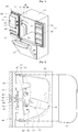
- Fig. 1 is a perspective view of a refrigerator according to an embodiment.
- a main body 100 of the refrigerator is divided into the top portion and bottom portion by a barrier 120.
- a refrigeration compartment 200 is disposed above the barrier 120 to keep its contents cool, and a freezer 300 is disposed below the barrier 120 to keep its contents frozen.
- a freezer door 320 is installed at the open front of the freezer 300 to open and close the freezer 300.
- the tilting type freezer door 320 opens in a frontal direction, with its upper end rotating outward within a predetermined angular range about an axis at the bottom end of the freezer 300.
- the description relating to a tilting structure of the freezer door 320 will be omitted for conciseness.
- Baskets or drawers are installed at the freezer door 320 to store contents below a freezing point.
- a cool air duct 140 is installed in the inner side surface of the main body 100 to guide the flow of cool air.
- the cool air duct 100 includes a supply duct 142 and a discharge duct 144.
- the supply duct 142 provides cool air from the freezer 300 into an icemaker case 400.
- the discharge duct 144 guides the cool air from the icemaker case 400 into the freezer 300.
- the supply duct 146 further includes a damper 146 that prevents the supply duct 146 from supplying the cool air when a refrigeration compartment door is open.
- the end portions of the supply duct 142 and the discharge duct 144 are exposed at the inner side surface to form a main body discharge port 142' and a main body inlet port 144' respectively.
- the main discharge port 142' discharges the cool air guided through the supply duct 142, and the main body inlet port 144' suctions the cool air discharged from the icemaker case 400 into the discharge duct 144.
- the cool air circulates between the freezer 300 and the icemaker case 400.
- the open front of the refrigeration compartment 200 is opened and closed by the refrigeration compartment door 220.
- the refrigeration compartment doors 220 are installed to be respectively rotatable toward the left and right of the main body 100.
- An outer case 222 is disposed on the front of the refrigeration compartment door 220, and an inner case is disposed on the rear of the refrigeration compartment door 220.
- An insulating material such as foamy polyurethane is filled between the outer case 222 and the inner case 224.
- the icemaker case 400 is disposed at the refrigeration compartment door 220.
- the icemaker case 400 protrudes toward the refrigerator to form an ice making compartment.
- the icemaker case 400 may be coupled to the inner case 224, or the icemaker case 400 and the inner case 224 may be manufactured in an integral type.
- a door inlet port 420 and a door discharge port 440 are respectively formed at the side of the icemaker case 400.
- the door inlet port 420 and the door discharge port 440 are formed in order to contact the main body discharge port 142 and the main body inlet port 144 while the refrigeration compartment door 220 is closed, such that the cool air duct 140 is connected to the icemaker case 400.
- the door inlet port 420 is connected to the main body discharge port 142' and the door discharge port 440 is connected to the main body inlet port 144'.
- the inside of the icemaker case 400 includes an icemaker (not shown) for making ice, an ice bank (not shown) for storing and providing ice, and an ice transferring device (not shown) for transferring ice. Additionally, a dispenser (not shown) may be disposed at the front of the refrigeration compartment door 220 for dispensing ice from the ice bank (not shown) into the outside. Once again, the ice maker, the ice maker, the ice bank, and the ice transferring device are not shown in Fig. 1 .
- the icemaker door 500 is mounted at the icemaker case to be rotatable.
- the icemaker door 500 having the upper part and lower part at the right side, which are hinged on the icemaker case 400, selectively opens and closes the open front of the icemaker case 400 by rotating the icemaker door 500.
- the outline of the icemaker case 400 and the rear outline of the icemaker door 500 contact each other to seal the icemaker case 400, and also a gasket 520 is installed along the rear outline of the icemaker door 500 to prevent the leakage of cool air.
- a lever assembly 600 is disposed in the icemaker door 500 to attach and detach the icemaker door 500 to and from the icemaker case 400.
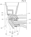
- Fig. 2 is a perspective view of the lever assembly 600 opening and closing the icemaker door 500 of the refrigerator of Fig. 1 .
- Fig. 3 is a sectional view of the icemaker door 500 and the icemaker case 400 of Fig. 2 restricted by the lever assembly 600.
- a mounting part 540 to which the lever assembly 600 is attached is formed at the left of the icemaker door 500.
- the mounting part 540 is depressed toward the bottom in a semicircular shape, and the depressed range is greater than the rotation range of the lever assembly 600.
- the lever assembly 600 is mounted to be rotatable in up and down directions perpendicular to the open and close directions of the icemaker door 500.
- the lever assembly 600 includes a handle 620 disposed outward the icemaker door 500, a lever 640 extending from the handle 620, and a protrusion part 660 extending from the lever 640.
- the handle 620 is disposed to be exposed to the outer of the mounting part 540.
- the handle 620 is bent toward the front to be spaced from one side of the mounting part 540, such that a user can easily grab the handle 620.
- the lever 640 is bent toward a holding part 460 of the icemaker case 400.
- the lever 640 includes a first extension part extending toward the left of the handle 620, a second extension part 644 perpendicularly bent with a predetermined angle from the first extension part 642, and a third extension part 646 bent perpendicular to the first extension part 642 from the second extension part 644.
- the lever 640 may be in a thin and long pole shape or a plate shape.
- the protrusion part 660 is formed perpendicular to the third extension part 646 of the lever 640.
- the protrusion part 660 rotates inside the holding part 460 of the icemaker case 400 according to control of the handle 620 for locking and unlocking.
- the protrusion part 660 prevents the icemaker door 500 from being opened when the protrusion part 660 is restricted by the holding part 460.
- the protrusion part 660 is formed by mounting an additional member to the third extension part 646, or by bending the end portion of the third extension part 646. Additionally, the length of the protrusion part 660 may be formed smaller than the opened size of the holding part 460.
- the lever 640 is fixed at the icemaker door 500 by using a fixing bracket 560.
- an insertion part with a semicircular form is formed at the center of the fixing bracket 560 to allow the third extension part 646 to be rotatable. Additionally, the fixing bracket 560 prevents the lever 640 from being disengaged and allows it to rotate.
- a stopper 580 may be formed at the mounting part 540 of the icemaker door 500 for allowing the lever 640 to rotate within a predetermined angular range.
- the stoppers 580 are spaced a predetermined distance apart from each other at the both sides of the first extension part 642, and protrudes with a predetermined height at the mounting part 540.
- the protruding height of the stopper 580 may be higher than the first extension part 642 of the lever assembly 600. Accordingly, the first extension part 642 is restricted by the stopper 580 when the lever assembly 600 rotates.
- a disengagement preventing member 582 is coupled to the outer surface of the stopper 580 to prevent the lever 640 from disengaging from the icemaker door 500. At this point, the disengagement preventing member 582 is coupled to the top of the stopper 580 by using a coupling member 584. The disengagement preventing member 582 is in a thin and long plate form.
- a cover 590 is attached to the mounting part 540 to cover a portion of the lever assembly 600.
- the cover 590 covers a portion of the lever 649, the fixing bracket 560, and the disengagement preventing member 582.
- the inside of the holding part 460 includes a space broader than the opened surface of the holding part 460, such that the protrusion part 660 is rotatable.
- the opened surface of the holding part 460 has a form extending in the top and down directions by the protruding length of the protrusion part 660 and extending in the right and left directions with a relatively narrow width. Accordingly, when the protrusion part 660 rotates in the holding part 460, it is restricted by the holding part 460 and stays at the inside of the holding part 460.
- the inner surface of the holding part 460 is formed slant to pull the icemaker door 500 toward the icemaker case 400 when the protrusion part 660 rotates for engagement.
- a holding groove 465 may be formed at the inner surface 461 of the holding part 460 to prevent the protrusion part 660 from moving when the protrusion part 660 is coupled to the holding part 460.
- the refrigeration compartment 200 and the freezer 300 maintains a predetermined low temperature by means of a cooling cycle.
- a portion of cool air supplied to the inner of the freezer 300 is supplied to the icemaker case 400 through the supply duct 142, such that ice can be made inside the icemaker case 400.
- the temperature of the cool air at the icemaker case 400 increases, such that the cool air returns to the freezer 300 through the discharge duct 144. Due to the cool air circulation, ice is made inside the icemaker case 400.
- Fig. 4 is a perspective view of when the lever assembly 600 of Fig. 2 releases the icemaker door 500.
- the handle 620 rotates toward the upper for opening the icemaker door 500.
- the lever assembler 600 rotates using the third extension part 646 fixed by the fixing bracket 560 as an axis. Additionally, when the handle 620 rotates with a predetermined angle, the first extension part 642 of the lever 640 engages with the upper portion of the stopper 580, such that the lever assembly 640 does not rotate beyond the upper portion.
- the protrusion part 660 freely enters and leaves the opened portion of the holding part 460.
- the protruding direction of the protruding part 660 is toward the bottom to correspond to the opened form of the holding part 460, and at this point, the space in the up and down directions of the holding part 460 is greater than the protruding protrusion part 660, such that the protrusion part 660 can freely enters and leaves the holding part 460 without restriction.
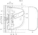
- Fig. 5 is a perspective view of when the icemaker door is open.
- the icemaker door 500 rotates toward the icemaker case 400.
- the handle 620 is located at the opening position.
- the icemaker door 500 rotates furthermore, and the protrusion part 660 is inserted into the inside of the holding part 460 as illustrated in Fig. 4 .
- the handle 620 When the protrusion part 660 is inserted into the holding part 460 and the handle 620 rotates toward the bottom, the handle 620 is positioned at the closing position. At this point, since the lever assembly 600 rotates using the third extension part 646 of the lever 640 as an axis, the protrusion part 660 bent toward a direction corresponding to the handle 620 at the bottom of the third extension part 646 rotates toward the top. Additionally, since the first extension part 642 of the lever 640 is restricted by the stopper 580 at the lower part, the lever assembly 600 does not rotate toward the bottom.
- the protrusion part 660 rotates while being inserted in the holding part 460, it contacts the inner surface 462 of the holding part 460 and its contact between them increases. According to the contact between protrusion part 660 and the inner surface 462, the icemaker door 500 is pulled toward the icemaker case 400. Additionally, when the protrusion part 660 is placed on the holding groove 462 of the holding part 460, it does not fall into the holding groove 462.
- the gasket 520 formed along the outline of the icemaker door 500 is compressed according to the contact of the icemaker door 500, such that the icemaker door 500 and the inner case 224 forming the outline of the icemaker case 400 completely contact each other in order to seal the inner space of the icemaker case 400.
- the protrusion part 660 when the protrusion part 660 completely rotates by continuously rotating the handle 620, the protrusion part 660 faces toward a direction perpendicular to the opened portion of the holding part 460. At this point, since the protrusion part 660 and the inner surface of the holding part 460 engage with each other, the protrusion part 660 is not easily disengaged from the holding part 460 and maintains its engagement with the holding part 460. Accordingly, the icemaker door 500 maintains its closed state.
- the refrigerator although its freezer is disposed on the lower part of the main body, a user does not need to stoop for getting ice, and since the icemaker door does not open by the impact of when the refrigerating door is opened and closed, the refrigerator can be used for industrial purpose.
Description
- The present disclosure relates to a refrigerator.
- A related art refrigerator is an appliance that cools its contents to a temperature below an ambient temperature. The refrigerator provides cold air generated by means of a refrigerant cycle to its storage compartments. The storage compartments consist of a freezer compartment and a refrigeration compartment.
- The freezer may include an icemaker used to make ice. The icemaker may be disposed in the door of the refrigeration compartment or in the freezer.
- However, when the freezer is disposed at the lower part of a main body of the refrigerator, the icemaker is also disposed in the lower part of the main body. In this case, a user needs to stoop to get ice from the icemaker.
- Additionally, the related art refrigerator has a freezer with a significantly smaller capacity than that of the refrigeration compartment. Therefore, when an icemaker is installed in such a freezer with a relatively small capacity, the capacity of the freezer is further decreased, so that the freezer of the refrigerator is unable to meet the needs of a user.
-
EP 1559973 discloses a refrigerator including an adiabatic space on an inside of a chilling chamber and an ice machine disposed in the adiabatic space.EP 1580504 discloses a cold air guide structure for an ice-making chamber in a cold chamber door.JP-S-61 - 150970 JP-S-63-142682 EP 1559973 andEP 1580504 both disclose a refrigerator as defined in the preamble of claim 1. - Embodiments provide an opening and closing structure of an icemaker case in a refrigerator, in which an icemaker door is equipped at the icemaker case on a door of the refrigerator, thereby providing an independent icemaker space.
Embodiments also provide an opening and closing structure of an icemaker case of a refrigerator, in which an icemaker door is selectively restricted by a lever assembly rotating perpendicular to an opening and closing direction of the icemaker door that selectively screens an icemaker case. - The present invention provides a refrigerator as set out in claim 1.
- In one embodiment, the refrigerator includes: an icemaker case on a refrigeration compartment door; an icemaker door on the icemaker case, the icemaker door being rotatable; a holding part on the icemaker case; and a lever assembly coupled to the icemaker door to be rotatable in order to engage or disengage with the holding part.
- The lever assembly includes a handle on the outer surface of the icemaker door; and a lever extending from the handle and coupled to the icemaker door to be rotatable. A protrusion part extending from the lever is arranged to engage or disengage with the holding part of the icemaker case such as by rotating the handle, and to allow the icemaker door to be pulled toward the icemaker case when the protrusion part rotates to engage with the holding part.
- The handle may rotate perpendicular to open and close directions of the icemaker door.
- The lever may extend from one side of the handle and is bent over toward the holding part.
- The protrusion part may be bent over at the end portion of the lever.
- The refrigerator may further include a fixing bracket for allowing the lever to rotate in the icemaker door.
- A portion of the handle may be bent over to be spaced from the outer surface of the icemaker door.
- The refrigerator may further include a stopper on both sides of the lever, the stopper allowing the lever to rotate within a predetermined angular range.
- The refrigerator may further include a disengagement preventing member on the outside of the lever, the disengagement preventing member preventing the lever from being disengaged from the icemaker door.
- One side of the holding part is formed at a slant.
- The refrigerator may further include a holding groove on one side of the holding part, the holding groove preventing the protrusion part from moving when the protrusion part is inserted into the holding part.
- The refrigerator may further include a cover on the icemaker door, the cover covering a portion of the lever.
- The refrigerator may further include a gasket, the gasket coupled to the icemaker door to seal an inner space of the icemaker case when the door is closed.
- The refrigerator may further include a cool air duct, the cool air duct being connected to the icemaker case when the door is closed.
- The cool air duct may include: a supply duct supplying cool air to the icemaker case; and a discharge duct discharging the cool air from the icemaker case.
- The refrigerator may further include a damper on the cool air duct, the damper preventing cool air supplying when the door is open.
- The refrigerator may further include a refrigeration compartment on the upper part of a main body of the refrigerator, the refrigeration compartment including a cool air duct.
- According to an embodiment, an icemaker is installed in a door of a refrigerator, such that a user does not need to stoop to get ice in a case where a refrigeration compartment is disposed on the upper part of the refrigerator.
- According to an embodiment, although a door of a refrigeration compartment receives impacts from the left and right directions while opening and closing the door, an icemaker door is not opened or closed due to an impact of opening and closing the door of the refrigeration by operating a lever assembly of the icemaker door up and down to open and close the icemaker door.
- According to an embodiment, since an icemaker door is not opened due to the impact of a door of a refrigeration compartment, a refrigerator does not cool its contents below a target temperature ("below a target temperature" may be caused by cool air of an icemaker case, which flows into the refrigeration compartment). Accordingly, the contents stored in the refrigeration compartment do not freeze and ice in the icemaker does not melt.
-
-
Fig. 1 is a perspective view of a refrigerator according to an embodiment. -
Fig. 2 is a perspective view of a lever assembly opening and closing an icemaker door of the refrigerator ofFig. 1 . -
Fig. 3 is a sectional view of an icemaker door and an icemaker case ofFig. 2 restricted by a level assembly. -
Fig. 4 is a perspective view of when the lever assembly ofFig. 2 releases an icemaker door. -
Fig. 5 is a perspective view of when the icemaker door ofFig. 2 is open. - Reference will now be made in detail to the embodiments of the present disclosure, examples of which are illustrated in the accompanying drawings. However, the idea of the present disclosure is not limited to an embodiment, and another embodiment within the range of the present disclosure of retrogressive another present disclosure may be easily provided by addition, modification, and deletion of another components.
-
Fig. 1 is a perspective view of a refrigerator according to an embodiment. - Referring to
Fig. 1 , the inside in amain body 100 of the refrigerator is divided into the top portion and bottom portion by abarrier 120. Arefrigeration compartment 200 is disposed above thebarrier 120 to keep its contents cool, and afreezer 300 is disposed below thebarrier 120 to keep its contents frozen. - There are a plurality of drawers and shelves for efficiently storing the contents in the
refrigeration compartment 200 and thefreezer 300, and various sizes of storage spaces are additionally formed if necessary. - A
freezer door 320 is installed at the open front of thefreezer 300 to open and close thefreezer 300. The tiltingtype freezer door 320 opens in a frontal direction, with its upper end rotating outward within a predetermined angular range about an axis at the bottom end of thefreezer 300. The description relating to a tilting structure of thefreezer door 320 will be omitted for conciseness. - Baskets or drawers are installed at the
freezer door 320 to store contents below a freezing point. - A
cool air duct 140 is installed in the inner side surface of themain body 100 to guide the flow of cool air. Thecool air duct 100 includes asupply duct 142 and adischarge duct 144. Thesupply duct 142 provides cool air from thefreezer 300 into anicemaker case 400. Thedischarge duct 144 guides the cool air from theicemaker case 400 into thefreezer 300. Thesupply duct 146 further includes adamper 146 that prevents thesupply duct 146 from supplying the cool air when a refrigeration compartment door is open. - The end portions of the
supply duct 142 and thedischarge duct 144 are exposed at the inner side surface to form a main body discharge port 142' and a main body inlet port 144' respectively. The main discharge port 142' discharges the cool air guided through thesupply duct 142, and the main body inlet port 144' suctions the cool air discharged from theicemaker case 400 into thedischarge duct 144. - Additionally, since the other end portions of the
supply duct 142 and thedischarge duct 144 are connected to the inside of thefreezer 300, the cool air circulates between thefreezer 300 and theicemaker case 400. - The open front of the
refrigeration compartment 200 is opened and closed by therefrigeration compartment door 220. Therefrigeration compartment doors 220 are installed to be respectively rotatable toward the left and right of themain body 100. - An
outer case 222 is disposed on the front of therefrigeration compartment door 220, and an inner case is disposed on the rear of therefrigeration compartment door 220. An insulating material such as foamy polyurethane is filled between theouter case 222 and theinner case 224. - The
icemaker case 400 is disposed at therefrigeration compartment door 220. Theicemaker case 400 protrudes toward the refrigerator to form an ice making compartment. Theicemaker case 400 may be coupled to theinner case 224, or theicemaker case 400 and theinner case 224 may be manufactured in an integral type. - A
door inlet port 420 and adoor discharge port 440 are respectively formed at the side of theicemaker case 400. Thedoor inlet port 420 and thedoor discharge port 440 are formed in order to contact the mainbody discharge port 142 and the mainbody inlet port 144 while therefrigeration compartment door 220 is closed, such that thecool air duct 140 is connected to theicemaker case 400. At this point, thedoor inlet port 420 is connected to the main body discharge port 142' and thedoor discharge port 440 is connected to the main body inlet port 144'. - The inside of the
icemaker case 400 includes an icemaker (not shown) for making ice, an ice bank (not shown) for storing and providing ice, and an ice transferring device (not shown) for transferring ice. Additionally, a dispenser (not shown) may be disposed at the front of therefrigeration compartment door 220 for dispensing ice from the ice bank (not shown) into the outside. Once again, the ice maker, the ice maker, the ice bank, and the ice transferring device are not shown inFig. 1 . - The
icemaker door 500 is mounted at the icemaker case to be rotatable. Theicemaker door 500 having the upper part and lower part at the right side, which are hinged on theicemaker case 400, selectively opens and closes the open front of theicemaker case 400 by rotating theicemaker door 500. - While the
icemaker door 500 is closed, the outline of theicemaker case 400 and the rear outline of theicemaker door 500 contact each other to seal theicemaker case 400, and also agasket 520 is installed along the rear outline of theicemaker door 500 to prevent the leakage of cool air. - Moreover, a
lever assembly 600 is disposed in theicemaker door 500 to attach and detach theicemaker door 500 to and from theicemaker case 400. -
Fig. 2 is a perspective view of thelever assembly 600 opening and closing theicemaker door 500 of the refrigerator ofFig. 1 .Fig. 3 is a sectional view of theicemaker door 500 and theicemaker case 400 ofFig. 2 restricted by thelever assembly 600. - Referring to
Figs. 2 and3 , a mountingpart 540 to which thelever assembly 600 is attached is formed at the left of theicemaker door 500. The mountingpart 540 is depressed toward the bottom in a semicircular shape, and the depressed range is greater than the rotation range of thelever assembly 600. - The
lever assembly 600 is mounted to be rotatable in up and down directions perpendicular to the open and close directions of theicemaker door 500. - The
lever assembly 600 includes ahandle 620 disposed outward theicemaker door 500, alever 640 extending from thehandle 620, and aprotrusion part 660 extending from thelever 640. - The
handle 620 is disposed to be exposed to the outer of the mountingpart 540. Thehandle 620 is bent toward the front to be spaced from one side of the mountingpart 540, such that a user can easily grab thehandle 620. - The
lever 640 is bent toward a holdingpart 460 of theicemaker case 400. At this point, thelever 640 includes a first extension part extending toward the left of thehandle 620, asecond extension part 644 perpendicularly bent with a predetermined angle from thefirst extension part 642, and athird extension part 646 bent perpendicular to thefirst extension part 642 from thesecond extension part 644. Thelever 640 may be in a thin and long pole shape or a plate shape. - The
protrusion part 660 is formed perpendicular to thethird extension part 646 of thelever 640. Theprotrusion part 660 rotates inside the holdingpart 460 of theicemaker case 400 according to control of thehandle 620 for locking and unlocking. Theprotrusion part 660 prevents theicemaker door 500 from being opened when theprotrusion part 660 is restricted by the holdingpart 460. - The
protrusion part 660 is formed by mounting an additional member to thethird extension part 646, or by bending the end portion of thethird extension part 646. Additionally, the length of theprotrusion part 660 may be formed smaller than the opened size of the holdingpart 460. - The
lever 640 is fixed at theicemaker door 500 by using afixing bracket 560. At this point, an insertion part with a semicircular form is formed at the center of the fixingbracket 560 to allow thethird extension part 646 to be rotatable. Additionally, the fixingbracket 560 prevents thelever 640 from being disengaged and allows it to rotate. - A
stopper 580 may be formed at the mountingpart 540 of theicemaker door 500 for allowing thelever 640 to rotate within a predetermined angular range. Thestoppers 580 are spaced a predetermined distance apart from each other at the both sides of thefirst extension part 642, and protrudes with a predetermined height at the mountingpart 540. - At this point, the protruding height of the
stopper 580 may be higher than thefirst extension part 642 of thelever assembly 600. Accordingly, thefirst extension part 642 is restricted by thestopper 580 when thelever assembly 600 rotates. - Additionally, a
disengagement preventing member 582 is coupled to the outer surface of thestopper 580 to prevent thelever 640 from disengaging from theicemaker door 500. At this point, thedisengagement preventing member 582 is coupled to the top of thestopper 580 by using acoupling member 584. Thedisengagement preventing member 582 is in a thin and long plate form. - A
cover 590 is attached to the mountingpart 540 to cover a portion of thelever assembly 600. Thecover 590 covers a portion of the lever 649, the fixingbracket 560, and thedisengagement preventing member 582. - The inside of the holding
part 460 includes a space broader than the opened surface of the holdingpart 460, such that theprotrusion part 660 is rotatable. The opened surface of the holdingpart 460 has a form extending in the top and down directions by the protruding length of theprotrusion part 660 and extending in the right and left directions with a relatively narrow width. Accordingly, when theprotrusion part 660 rotates in the holdingpart 460, it is restricted by the holdingpart 460 and stays at the inside of the holdingpart 460. - Moreover, the inner surface of the holding
part 460 is formed slant to pull theicemaker door 500 toward theicemaker case 400 when theprotrusion part 660 rotates for engagement. At this point, a holdinggroove 465 may be formed at the inner surface 461 of the holdingpart 460 to prevent theprotrusion part 660 from moving when theprotrusion part 660 is coupled to the holdingpart 460. - An operation of an embodiment having the above components is described below.
- When power is applied from the external, the
refrigeration compartment 200 and thefreezer 300 maintains a predetermined low temperature by means of a cooling cycle. A portion of cool air supplied to the inner of thefreezer 300 is supplied to theicemaker case 400 through thesupply duct 142, such that ice can be made inside theicemaker case 400. The temperature of the cool air at theicemaker case 400 increases, such that the cool air returns to thefreezer 300 through thedischarge duct 144. Due to the cool air circulation, ice is made inside theicemaker case 400. -
Fig. 4 is a perspective view of when thelever assembly 600 ofFig. 2 releases theicemaker door 500. - Referring to
Fig. 4 , thehandle 620 rotates toward the upper for opening theicemaker door 500. At this point, thelever assembler 600 rotates using thethird extension part 646 fixed by the fixingbracket 560 as an axis. Additionally, when thehandle 620 rotates with a predetermined angle, thefirst extension part 642 of thelever 640 engages with the upper portion of thestopper 580, such that thelever assembly 640 does not rotate beyond the upper portion. - When the
handle 620 rotates up to the opening position, theprotrusion part 660 freely enters and leaves the opened portion of the holdingpart 460. The protruding direction of theprotruding part 660 is toward the bottom to correspond to the opened form of the holdingpart 460, and at this point, the space in the up and down directions of the holdingpart 460 is greater than the protrudingprotrusion part 660, such that theprotrusion part 660 can freely enters and leaves the holdingpart 460 without restriction. -
Fig. 5 is a perspective view of when the icemaker door is open. - Referring to
Fig. 5 , when theicemaker door 500 is pulled, theprotrusion part 660 releases from the opened portion of the holdingpart 460. - Then, the
icemaker door 500 rotates toward theicemaker case 400. At this point, thehandle 620 is located at the opening position. Theicemaker door 500 rotates furthermore, and theprotrusion part 660 is inserted into the inside of the holdingpart 460 as illustrated inFig. 4 . - When the
protrusion part 660 is inserted into the holdingpart 460 and thehandle 620 rotates toward the bottom, thehandle 620 is positioned at the closing position. At this point, since thelever assembly 600 rotates using thethird extension part 646 of thelever 640 as an axis, theprotrusion part 660 bent toward a direction corresponding to thehandle 620 at the bottom of thethird extension part 646 rotates toward the top. Additionally, since thefirst extension part 642 of thelever 640 is restricted by thestopper 580 at the lower part, thelever assembly 600 does not rotate toward the bottom. - Referring to
Fig. 2 , when theprotrusion part 660 rotates while being inserted in the holdingpart 460, it contacts theinner surface 462 of the holdingpart 460 and its contact between them increases. According to the contact betweenprotrusion part 660 and theinner surface 462, theicemaker door 500 is pulled toward theicemaker case 400. Additionally, when theprotrusion part 660 is placed on the holdinggroove 462 of the holdingpart 460, it does not fall into the holdinggroove 462. - At this point, the
gasket 520 formed along the outline of theicemaker door 500 is compressed according to the contact of theicemaker door 500, such that theicemaker door 500 and theinner case 224 forming the outline of theicemaker case 400 completely contact each other in order to seal the inner space of theicemaker case 400. - On the other hand, when the
protrusion part 660 completely rotates by continuously rotating thehandle 620, theprotrusion part 660 faces toward a direction perpendicular to the opened portion of the holdingpart 460. At this point, since theprotrusion part 660 and the inner surface of the holdingpart 460 engage with each other, theprotrusion part 660 is not easily disengaged from the holdingpart 460 and maintains its engagement with the holdingpart 460. Accordingly, theicemaker door 500 maintains its closed state. - In the refrigerator according to the embodiment, although its freezer is disposed on the lower part of the main body, a user does not need to stoop for getting ice, and since the icemaker door does not open by the impact of when the refrigerating door is opened and closed, the refrigerator can be used for industrial purpose.
Claims (13)
- A refrigerator comprising:an icemaker case (400) disposed on a refrigeration compartment door (220); and an icemaker door (500) disposed on the icemaker case (400), the icemaker door (500) being rotatable; characterized by:a holding part (460) disposed on the icemaker case (400); anda lever assembly (600) coupled to the icemaker door (500) to be rotatable in order to engage or disengage with the holding part (460), wherein the lever assembly comprises:a handle (620) disposed on an outer surface of the icemaker door (500); a lever (640) extending from the handle (620) and coupled to the icemaker door (500) to be rotatable; anda protrusion part (660) extending from the lever (640) and arranged to engage or disengage with the holding part (460) of the icemaker case (400) by rotating the handle (620),wherein one side of the holding part (460) is formed at a slant to allow the icemaker door (500) to be pulled toward the icemaker case (400) when the protrusion part (660) rotates to engage with the holding part (460).
- The refrigerator according to claim 1, wherein the handle (600) is perpendicularly rotated to the open and close direction of the icemaker door (500).
- The refrigerator according to claim 1, wherein the lever (640) extends from one side of the handle (620) and is bent over toward the holding part (460).
- The refrigerator according to claim 1, wherein the protrusion part (660) is bent over at the end portion of the lever (640).
- The refrigerator according to claim 1, further comprising a fixing bracket (560) for allowing the lever (640) to rotate in the icemaker door (500).
- The refrigerator according to claim 1, wherein a portion of the handle (620) is bent over to be spaced from the outer surface of the icemaker door (500).
- The refrigerator according to claim 1, further comprising stoppers (580) coupled on both sides of the lever (640), the stoppers (580) allowing the lever (640) to rotate within a predetermined angular range.
- The refrigerator according to claim 1, further comprising a disengagement preventing member (582) on the outside of the lever (640), the disengagement preventing member (582) preventing the lever (640) from disengaging with the icemaker door (500).
- The refrigerator according to claim 1, further comprising a holding groove (465) on one side of the holding part (460), the holding groove (465) preventing the protrusion part (660) from moving when the protrusion part (660) is inserted into the holding part (460).
- The refrigerator according to claim 1, further comprising a cover (590) disposed on the icemaker door (500), the cover (590) covering a portion of the lever (640).
- The refrigerator according to claim 1, further comprising a gasket (520), the gasket (520) coupled to the icemaker door (600) to seal an inner space of the icemaker case (400) when the door is closed.
- The refrigerator according to claim 1, further comprising a cool air duct (140) being connected to the icemaker case (400) when the door is closed.
- The refrigerator according to claim 12, wherein the cool air duct (140) comprises:a supply duct (142) supplying cool air to the icemaker case (400); anda discharge duct (144) discharging the cool air from the icemaker case (400).
Applications Claiming Priority (2)
| Application Number | Priority Date | Filing Date | Title |
|---|---|---|---|
| KR1020060064874A KR100767844B1 (en) | 2006-07-11 | 2006-07-11 | A refrigerator |
| PCT/KR2007/003363 WO2008007901A1 (en) | 2006-07-11 | 2007-07-11 | Refrigerator |
Publications (3)
| Publication Number | Publication Date |
|---|---|
| EP2109745A1 EP2109745A1 (en) | 2009-10-21 |
| EP2109745A4 EP2109745A4 (en) | 2014-04-23 |
| EP2109745B1 true EP2109745B1 (en) | 2017-11-01 |
Family
ID=38815039
Family Applications (1)
| Application Number | Title | Priority Date | Filing Date |
|---|---|---|---|
| EP07768696.2A Active EP2109745B1 (en) | 2006-07-11 | 2007-07-11 | Refrigerator |
Country Status (7)
| Country | Link |
|---|---|
| US (1) | US8966931B2 (en) |
| EP (1) | EP2109745B1 (en) |
| KR (1) | KR100767844B1 (en) |
| CN (1) | CN101466988B (en) |
| AU (1) | AU2007273334B2 (en) |
| MX (1) | MX2008014660A (en) |
| WO (1) | WO2008007901A1 (en) |
Families Citing this family (8)
| Publication number | Priority date | Publication date | Assignee | Title |
|---|---|---|---|---|
| KR101658998B1 (en) * | 2009-04-02 | 2016-09-23 | 엘지전자 주식회사 | refrigerator |
| KR101624557B1 (en) * | 2009-11-03 | 2016-06-07 | 엘지전자 주식회사 | Refrigerator with ice making room |
| US8522566B2 (en) * | 2009-12-14 | 2013-09-03 | Whirlpool Corporation | Mega ice bin |
| KR20110072364A (en) * | 2009-12-22 | 2011-06-29 | 엘지전자 주식회사 | Refrigerator |
| EP2713123A3 (en) * | 2012-09-27 | 2017-08-30 | Whirlpool EMEA S.p.A | Refrigeration apparatus for food products |
| KR102267891B1 (en) | 2014-12-01 | 2021-06-23 | 삼성전자주식회사 | Refrigerator |
| US10712074B2 (en) | 2017-06-30 | 2020-07-14 | Midea Group Co., Ltd. | Refrigerator with tandem evaporators |
| US11846462B2 (en) | 2021-03-19 | 2023-12-19 | Electrolux Home Products, Inc. | Door mounted chilled component with direct cooling |
Family Cites Families (19)
| Publication number | Priority date | Publication date | Assignee | Title |
|---|---|---|---|---|
| US1862715A (en) * | 1931-01-19 | 1932-06-14 | Nat Brass Co | Right and left hand latch |
| US4413848A (en) * | 1981-01-09 | 1983-11-08 | The Knapheide Mfg. Co. | Latching mechanism for panels |
| JPS61150970U (en) * | 1985-03-08 | 1986-09-18 | ||
| JPS63142682U (en) | 1987-03-09 | 1988-09-20 | ||
| US5265921A (en) * | 1993-03-24 | 1993-11-30 | Nikitas John P | Refrigerator lock apparatus |
| JPH1047842A (en) * | 1996-08-07 | 1998-02-20 | Matsushita Refrig Co Ltd | Door for refrigerator |
| KR100261346B1 (en) * | 1997-08-29 | 2000-07-01 | 전주범 | Door handle |
| KR19990029025U (en) * | 1997-12-27 | 1999-07-15 | 윤종용 | Refrigerator with lock |
| KR100281961B1 (en) * | 1998-11-28 | 2001-02-15 | 전주범 | Door opening of the refrigerator |
| CN2372638Y (en) * | 1999-05-06 | 2000-04-05 | 海尔集团公司 | Freezed room small door in refrigerator |
| KR20050077844A (en) | 2004-01-28 | 2005-08-04 | 엘지전자 주식회사 | Side by side type refrigerator |
| EP1580504B1 (en) | 2004-03-24 | 2017-03-29 | LG Electronics, Inc. | Cold air guide structure for ice-making chamber in cold chamber door |
| KR100671567B1 (en) * | 2004-05-18 | 2007-01-18 | 엘지전자 주식회사 | Sense apparatus for full ice of ice maker in refrigerator |
| US7188479B2 (en) * | 2004-10-26 | 2007-03-13 | Whirlpool Corporation | Ice and water dispenser on refrigerator compartment door |
| US7228702B2 (en) * | 2004-10-26 | 2007-06-12 | Whirlpool Corporation | Ice making and dispensing system |
| KR100621239B1 (en) * | 2004-11-09 | 2006-09-12 | 엘지전자 주식회사 | Duct structure of cooled air in refrigerator |
| US7410230B2 (en) * | 2005-01-12 | 2008-08-12 | Whirlpool Corporation | Refrigerator with multi-piece mullion having stepped offset |
| KR100688659B1 (en) | 2005-03-28 | 2007-03-02 | 엘지전자 주식회사 | Refrigerator |
| US7549297B2 (en) * | 2005-05-18 | 2009-06-23 | Maytag Corporation | Refrigerator air control damper for ice compartment |
-
2006
- 2006-07-11 KR KR1020060064874A patent/KR100767844B1/en active IP Right Grant
-
2007
- 2007-07-11 AU AU2007273334A patent/AU2007273334B2/en active Active
- 2007-07-11 WO PCT/KR2007/003363 patent/WO2008007901A1/en active Application Filing
- 2007-07-11 CN CN2007800221197A patent/CN101466988B/en active Active
- 2007-07-11 MX MX2008014660A patent/MX2008014660A/en active IP Right Grant
- 2007-07-11 US US12/300,311 patent/US8966931B2/en active Active
- 2007-07-11 EP EP07768696.2A patent/EP2109745B1/en active Active
Non-Patent Citations (1)
| Title |
|---|
| None * |
Also Published As
| Publication number | Publication date |
|---|---|
| WO2008007901A1 (en) | 2008-01-17 |
| EP2109745A4 (en) | 2014-04-23 |
| CN101466988A (en) | 2009-06-24 |
| US8966931B2 (en) | 2015-03-03 |
| AU2007273334B2 (en) | 2010-04-22 |
| CN101466988B (en) | 2011-01-12 |
| EP2109745A1 (en) | 2009-10-21 |
| KR100767844B1 (en) | 2007-10-17 |
| US20090151386A1 (en) | 2009-06-18 |
| MX2008014660A (en) | 2008-11-27 |
| AU2007273334A1 (en) | 2008-01-17 |
Similar Documents
| Publication | Publication Date | Title |
|---|---|---|
| EP2109745B1 (en) | Refrigerator | |
| US10465975B2 (en) | Refrigerator | |
| EP3619484B1 (en) | Refrigerator | |
| EP1856463B1 (en) | Refrigerator | |
| US7866181B2 (en) | Refrigerator with ice-making unit | |
| RU2484392C1 (en) | Refrigerator | |
| US20110146331A1 (en) | Refrigerator | |
| US20120000238A1 (en) | Refrigerator with selective airflow passage between the icemaker and the ice making evaporator | |
| EP3497387B1 (en) | Refrigerator | |
| KR101294519B1 (en) | Refrigerator | |
| EP3168552B1 (en) | Refrigerator | |
| US20080053138A1 (en) | Refrigerator | |
| KR20080106771A (en) | Ice making apparatus and refrigerator having the same | |
| US20100154458A1 (en) | Icemaker for a refrigerator | |
| KR20100113193A (en) | Refrigerator | |
| KR101698080B1 (en) | Mobile cooler with an ice maker | |
| US20190331396A1 (en) | Ice Maker and Refrigerator Having Same | |
| KR101467271B1 (en) | Refrigerator | |
| KR101450654B1 (en) | An ice maker of bottom freezer type refrigerator | |
| JP2000088450A (en) | Storage cabinet | |
| KR20100113192A (en) | Refrigerator | |
| KR101132481B1 (en) | An ice dispenser for refrigerator | |
| KR100651308B1 (en) | A refrigerator | |
| KR20240051626A (en) | Refrigerator | |
| JP2002098463A (en) | Refrigerator |
Legal Events
| Date | Code | Title | Description |
|---|---|---|---|
| PUAI | Public reference made under article 153(3) epc to a published international application that has entered the european phase |
Free format text: ORIGINAL CODE: 0009012 |
|
| 17P | Request for examination filed |
Effective date: 20081114 |
|
| AK | Designated contracting states |
Kind code of ref document: A1 Designated state(s): AT BE BG CH CY CZ DE DK EE ES FI FR GB GR HU IE IS IT LI LT LU LV MC MT NL PL PT RO SE SI SK TR |
|
| RBV | Designated contracting states (corrected) |
Designated state(s): DE GB IT |
|
| A4 | Supplementary search report drawn up and despatched |
Effective date: 20140320 |
|
| RIC1 | Information provided on ipc code assigned before grant |
Ipc: F25D 23/02 20060101AFI20140314BHEP Ipc: F25D 23/04 20060101ALI20140314BHEP |
|
| 17Q | First examination report despatched |
Effective date: 20160906 |
|
| GRAP | Despatch of communication of intention to grant a patent |
Free format text: ORIGINAL CODE: EPIDOSNIGR1 |
|
| INTG | Intention to grant announced |
Effective date: 20170515 |
|
| GRAS | Grant fee paid |
Free format text: ORIGINAL CODE: EPIDOSNIGR3 |
|
| GRAA | (expected) grant |
Free format text: ORIGINAL CODE: 0009210 |
|
| AK | Designated contracting states |
Kind code of ref document: B1 Designated state(s): DE GB IT |
|
| REG | Reference to a national code |
Ref country code: GB Ref legal event code: FG4D |
|
| REG | Reference to a national code |
Ref country code: DE Ref legal event code: R096 Ref document number: 602007052887 Country of ref document: DE |
|
| REG | Reference to a national code |
Ref country code: DE Ref legal event code: R097 Ref document number: 602007052887 Country of ref document: DE |
|
| PG25 | Lapsed in a contracting state [announced via postgrant information from national office to epo] |
Ref country code: IT Free format text: LAPSE BECAUSE OF FAILURE TO SUBMIT A TRANSLATION OF THE DESCRIPTION OR TO PAY THE FEE WITHIN THE PRESCRIBED TIME-LIMIT Effective date: 20171101 |
|
| PLBE | No opposition filed within time limit |
Free format text: ORIGINAL CODE: 0009261 |
|
| STAA | Information on the status of an ep patent application or granted ep patent |
Free format text: STATUS: NO OPPOSITION FILED WITHIN TIME LIMIT |
|
| 26N | No opposition filed |
Effective date: 20180802 |
|
| PGFP | Annual fee paid to national office [announced via postgrant information from national office to epo] |
Ref country code: GB Payment date: 20230607 Year of fee payment: 17 |
|
| PGFP | Annual fee paid to national office [announced via postgrant information from national office to epo] |
Ref country code: DE Payment date: 20230607 Year of fee payment: 17 |