EP2109517B1 - Insertion and release tool for pipe fitting arrangement and method using such tool - Google Patents
Insertion and release tool for pipe fitting arrangement and method using such tool Download PDFInfo
- Publication number
- EP2109517B1 EP2109517B1 EP08707448A EP08707448A EP2109517B1 EP 2109517 B1 EP2109517 B1 EP 2109517B1 EP 08707448 A EP08707448 A EP 08707448A EP 08707448 A EP08707448 A EP 08707448A EP 2109517 B1 EP2109517 B1 EP 2109517B1
- Authority
- EP
- European Patent Office
- Prior art keywords
- housing
- pipe
- tool
- engagement means
- engagement
- Prior art date
- Legal status (The legal status is an assumption and is not a legal conclusion. Google has not performed a legal analysis and makes no representation as to the accuracy of the status listed.)
- Not-in-force
Links
Images




Classifications
-
- B—PERFORMING OPERATIONS; TRANSPORTING
- B25—HAND TOOLS; PORTABLE POWER-DRIVEN TOOLS; MANIPULATORS
- B25B—TOOLS OR BENCH DEVICES NOT OTHERWISE PROVIDED FOR, FOR FASTENING, CONNECTING, DISENGAGING, OR HOLDING
- B25B27/00—Hand tools, specially adapted for fitting together or separating parts or objects whether or not involving some deformation, not otherwise provided for
- B25B27/02—Hand tools, specially adapted for fitting together or separating parts or objects whether or not involving some deformation, not otherwise provided for for connecting objects by press fit or detaching same
- B25B27/10—Hand tools, specially adapted for fitting together or separating parts or objects whether or not involving some deformation, not otherwise provided for for connecting objects by press fit or detaching same inserting fittings into hoses
-
- F—MECHANICAL ENGINEERING; LIGHTING; HEATING; WEAPONS; BLASTING
- F16—ENGINEERING ELEMENTS AND UNITS; GENERAL MEASURES FOR PRODUCING AND MAINTAINING EFFECTIVE FUNCTIONING OF MACHINES OR INSTALLATIONS; THERMAL INSULATION IN GENERAL
- F16L—PIPES; JOINTS OR FITTINGS FOR PIPES; SUPPORTS FOR PIPES, CABLES OR PROTECTIVE TUBING; MEANS FOR THERMAL INSULATION IN GENERAL
- F16L37/00—Couplings of the quick-acting type
- F16L37/08—Couplings of the quick-acting type in which the connection between abutting or axially overlapping ends is maintained by locking members
- F16L37/084—Couplings of the quick-acting type in which the connection between abutting or axially overlapping ends is maintained by locking members combined with automatic locking
- F16L37/091—Couplings of the quick-acting type in which the connection between abutting or axially overlapping ends is maintained by locking members combined with automatic locking by means of a ring provided with teeth or fingers
- F16L37/0915—Couplings of the quick-acting type in which the connection between abutting or axially overlapping ends is maintained by locking members combined with automatic locking by means of a ring provided with teeth or fingers with a separate member for releasing the coupling
-
- Y—GENERAL TAGGING OF NEW TECHNOLOGICAL DEVELOPMENTS; GENERAL TAGGING OF CROSS-SECTIONAL TECHNOLOGIES SPANNING OVER SEVERAL SECTIONS OF THE IPC; TECHNICAL SUBJECTS COVERED BY FORMER USPC CROSS-REFERENCE ART COLLECTIONS [XRACs] AND DIGESTS
- Y10—TECHNICAL SUBJECTS COVERED BY FORMER USPC
- Y10T—TECHNICAL SUBJECTS COVERED BY FORMER US CLASSIFICATION
- Y10T29/00—Metal working
- Y10T29/53—Means to assemble or disassemble
- Y10T29/5367—Coupling to conduit
Definitions
- the present invention refers to an insertion and release tool for a pipe fitting arrangement according to the pre-amble of claim 1 and a method for using such a tool.
- a pipe fitting arrangement comprises a housing 100 into which a pipe, not shown, is to be inserted.
- the housing 100 is provided with a first shoulder 102, having a chamfer 103, a projection 104 defining a second and third shoulder, both being provided with a chamfer 105a, 105b, and a fourth shoulder 106 next to a rolled-over end 108.
- a sealing ring 110 and between the projection 104 and the rolled-over end 108 a grip ring 112 with internal teeth 114 is provided.
- the projection 104 fulfills a plurality of functions, namely by providing a spacer between the sealing ring 110 and the gripping ring 112, limiting the movement of the sealing ring 110 in the pipe removal direction, limiting a deformation of the grip ring 112 in the pipe insertion direction and supporting the pipe.
- the diameter of the opening 109, defined by the rolled-over end 108 and into which the pipe is to be inserted, is larger than the diameter of the projection 104 such that said end 108 will not engage the pipe, whereas the teeth I 14 are configured to engage the pipe.
- WO 2005/114031 A2 also describes a release tool 200 shown in figure 1b enclosed herewith.
- a release tool 200 is necessary to release the pipe from the pipe fitting arrangement shown in figure 1a by urging the teeth 114 of the grip ring 112 out of engagement with the pipe.
- the release tool 200 is provided with an opening 202 for the pipe and a main body 204 with a projection 206 adapted to be inserted into the housing 100, said insertion being limited by the projection 104 of the housing 100.
- the main body 204 is provided with a V-shaped split 204a as well as a material thinning or recess 204b for facilitating an attachment around the pipe and a front face 204c for engagement with the housing 100, in particular the rolled-over end 108 thereof.
- the projection 206 comprises a cylindrical portion 206a and chamfered portion 206b facilitating the insertion between the pipe and the housing 100.
- the tool In order to engage the release tool 200 of figure 1b with the pipe fitting arrangement of figure 1a , the tool is aligned relative to the pipe such that the longitudinal axis thereof is running parallel to the longitudinal axis of the pipe. Then the release tool 200 can be opened in the region of the split 204a and thereafter pushed against the pipe with the opened split 204a facing the pipe, whereas the region next to the recess 204b serves as a hinge for facilitating such an opening. As soon as the pipe has been completely entered into the opening 202 the split 204a will close again due to spring forces provided by the main body 204.
- the release tool 200 can be slided on the pipe in the direction of the housing 100 with the projection 206 leading and, thus, when passing the teeth 114, forcing them radially outward. Finally, the pipe can be drawn out off the housing 100 as it is no longer retained therein by the teeth 114. As soon as the pipe has been completely removed out of the housing 100, the release tool 200 can also be removed therefrom.
- Said release tool for disengaging teeth from a pipe in order to remove the pipe from a coupling is known from EP 1 521 027 B1 .
- Said release tool comprises a first member in form of a pusher to be inserted into the coupling to urge the teeth radially outward and, thus, releasing the engagement thereof with the pipe, and a second member in form of a cap to be screwed onto the coupling for engaging the first member.
- the cap can be screwed onto the coupling as well as the pusher and thereby moving the pusher in the pipe insertion direction, whereas an unscrewing of the cap leads to a movement of the pusher in the pipe removal direction.
- the first spring means is comprised by the actuation means.
- the first engagement means comprises a main body, in particular in form of a ring, having at least one face or shoulder, adapted to engage the end of the housing into which the pipe is to be inserted or from which the pipe is to be removed, and a first opening for the pipe, said first opening preferably being defined by the face or shoulder and/or being variable and/or adjustable, most preferably via the actuation means and/or second spring means, in particular the second spring means and the first spring means being formed together.
- the main body is deformable, preferably being formed at least partly from elastic or spring material, and/or can be opened, preferably by comprising at least one split, most preferably two opposing splits.
- An embodiment can be further characterized in that the main body comprises at least one, in particular angled, extension next to one split, preferably two such extensions one on each side of the split, to facilitate entering of the pipe into the first engagement means through the split.
- the main body is formed by two halves being connected to each other, preferably via a third spring means, in particular the third spring means and the second spring means being formed together, and/or at at least one second joint, in particular in form of a pivot, arranged next to a split, in particular on both sides of the slit, most preferably the split opposite the extension(s), in particular the second joint being identical to the first joint
- the at least one part of the first engagement means has a tube-like form, preferably having at least one split, most preferably two opposing splits and/or is provided with a chamfer or tapering off towards its free end for facilitating its insertion into the housing.
- the at least one part of the first engagement means is formed as a projection of the main body surrounding the first opening at least partly.
- the second engagement means comprises first holding means for engagement with the housing as well as second holding means for engagement with the first engagement means, the housing being preferably locatable between the two holding means and/or the holding means being preferably moveable relative to each other via the actuation means, in particular the first spring means being arranged between the two holding means.
- the first holding means can comprise a substantially U-shaped first body, preferably in form of a first jaw, and/or the second holding means can comprise a substantially U-shaped second body, preferably in form of a second jaw.
- the first holding means has a second opening for the housing and/or the second holding means has a third opening for the pipe, the second and/or third opening being preferably variable and/or adjustable, in particular via the actuation means and/or third spring means for facilitating the insertion of the pipe and/or housing, the third spring means most preferably being formed together with the first and/or second spring means.
- the second opening can be provided between two halves of the first holding means being pivotably connected to each other, preferably via at least one third pivot, most preferably being identical to the first joint, and/or the third opening can be provided between two halves of the second holding means being pivotably connected to each other, preferably via at least one fourth joint, most preferably being identical with the third joint.
- first, second and/or third spring means comprise(s) at least one elastic ring, in particular a rubber O-ring, arranged substantially perpendicular to a longitudinal axis of the first, second and/or third opening, preferably the first spring means being arranged within at least one recess of the main body and/ the first holding means, or the first, second and/or third spring means (24'ga, 24'gb, 24'h) comprise(s) at least one spiral spring.
- the first holding means can be adapted to engage the housing outer surface between a first internal projection or shoulder or bend of the housing for limiting insertion of the pipe into the housing and a second internal projection or shoulder or bend of the housing for limiting movement of a sealing ring in the pipe insertion direction or between said second internal projection or shoulder or bend and a third internal projection or shoulder or bend of the housing for limiting movement of the grip ring in the pipe insertion direction and/or limiting movement of the sealing ring in the pipe removal direction.
- the first holding means is adapted to engage the housing outer surface next to at least one external shoulder or projection and/or within a recess or groove.
- the handle and the actuation means are formed as a plier's and/or ratchet's handle and actuation means and/or comprise tong grippers.
- the handle preferably in U-shape
- the handle is connected to the first and the second holding means, most preferably with one holding means provided at each free end and/or the handle, preferably comprising a pair of tong grippers, is, in particular detachably, connectable with the first and second holding means, preferablyvia gripper fingers and/or a snap connection.
- the free ends of the handle are moveable towards each other via the actuating means and away from each other, preferably by moving a slider bar, in particular within a slot provided in each arm of the U-shaped handle, to the free ends and away therefrom.
- the slider bar can be positioned substantially parallel to the longitudinal axis of the first, second and/or third opening and/or fixable in at least two positions.
- the tool of an embodiment can be further characterized in that the slider bar has at least one recess, preferably four recesses, for the engagement with the handle in order to guide the sliding thereof, said recesses being most preferably variable and/or adjustable in order to adapt the tool to different pipe fitting arrangements.
- each gripper finger is provided with a projection
- the first as well as the second holding means are each provided with a recess for such a projection in order to allow a snap connection.
- the method of inserting a pipe into the housing comprises the following steps:
- Step c) can comprise that the pipe is inserted until it abuts against the housing, preferably the first projection or shoulder or bend thereof.
- the removal of the pipe from the housing with the teeth engaging the pipe comprises the following steps:
- step a) and/or step i) comprise(s) that the housing is aligned relative to the tool, preferably the longitudinal axis of the housing being parallel to the longitudinal axis of the first, second and third opening, and the tool is pushed against the housing, preferably perpendicular to said longitudinal axes.
- step i) comprises that the split(s) of the first engagement means is/are opened when pushing the tool against the housing as soon as abutting against the pipe and closed when the first engagement means completely surrounds the pipe, preferably by the second spring means.
- step b) and/or step ii) comprise(s) that the at least one part of the first engagement means is inserted into the housing until the teeth of the grip ring abut against the housing, preferably the third projection or shoulder or bend thereof.
- step b) and/or step ii) comprise(s) that the slider bar is moved towards the holding means to bring the tool in its second close position
- step d) and/or step iv) comprise(s) that the slider bar is moved away from the holding means to bring the tool in its first open position
- the method can be characterized by assembling the tool prior to insertion of the pipe into the housing or removal of the pipe from the housing, in particular by a snap connection, preferably between the tong grippers and the second engagement means, and/or disassembling the tool after insertion of the pipe into the housing or removal the pipe from the housing, in particular by a snap connection, preferably between the tong grippers and the second engagement means.
- a combined insertion and release tool can be provided with a simple structure and easy to be handled by a user.
- the tool of the invention allows the user to locate a fitting or housing within the tool, whereupon by mechanical means the diameter of a grip ring within said housing can be opened such that a pipe without being damaged can be inserted into the housing and removed therefrom.
- the work of the user is further facilitated, not only by the easy handling of the tool, but also by reducing the efforts required by the user to manually push the pipe into the housing and thus complete the joint in order to obtain a fluid tight, even gas tight, pipe fitting arrangement.
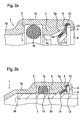
- a pipe fitting arrangement comprises a housing I having a first shoulder 2 with a chamfer 3, a projection 4 providing a second shoulder with a chamfer 5b, a third shoulder with a chamfer 5a next to a fourth shoulder 6 and a folded end 8 defining an opening 9.
- a sealing ring 10 is arranged between the first shoulder 2 and the second shoulder of the projection 4 , whereas between the fourth shoulder 6 and the folded end 8 a grip ring 12 is arranged.
- the grip ring 12 comprises first external teeth 13 engaging the housing 1 and second internal teeth 14 engaging a pipe as soon as having been inserted into the housing I through the opening 9 as shown in figure 2b , with the movement of the grip ring 12 being limited by the third and fourth shoulder of the projection 4.
- figure 2b is depicting a pipe fitting arrangement with a pipe 50 ensuring a seal due to compressing the sealing ring 10 while abutting in particular against the projection 4, whereas retention of the pipe 50 within the housing I is provided by the engagement of the internal teeth 14 of the grip ring 12 on the pipe 50. Still further, a rotation of the pipe 50 relative to the housing 1 is inhibited by the opposite orientation of the external and internal teeth 13, 14 of the grip ring 12.
- the internal teeth 14 engaging the pipe 50 and the external teeth 13 engaging the housing I in addition ensure electric continuity between the pipe 50 and the housing 1 as the grip ring 12 is formed from a metal.
- the housing 1 is provided with a step like outer surface, namely a first step 1a in the region of the sealing ring 10 and grip ring 12 comprising the first shoulder 2 and the projection 4 and a second step 1 b provided between the first shoulder 2 and a bend 1c of the housing 1 serving as a limit stop for the pipe 50.
- the pincers like tool 20 is provided with an opening 22 for the pipe fitting arrangement, a first engagement means for engaging the housing 1 and/or the pipe 50 and a second engagement means for engaging the first engagement means and/or the housing 1 as explained in detail in the following:
- the second engagement means comprises a first holding means in form of a jaw 34 for engaging the housing 1 within an opening 34a and a second holding means in form of a jaw 36 for engaging the first engaging means.
- the jaws 34 and 36 are connected with each other via an U-shaped handle 30 provided with slots 32 along its two arms.
- the second jaw 36 is also provided with two recesses 36a for positioning a rubber O-ring 38 forming spring means, which also surrounds the two parts of the ring 24 next to the further split 24e.
- the ring 24 is connected to the second jaw 36 by the pivot 24f.
- the tool 20 is shown in its open position with a maximum distance between the two tool jaws 34, 36. Said distance can be reduced by actuating an actuation means comprising a slider bar 40 guided within the slots 32.
- the slider bar 40 is provided with recesses 42, 44 (as can be best seen in figure 4a ) in order to stay within the slots 32.
- the tool 20 facilitates the connection and the release of a pipe fitting arrangement, is easy to handle and, simultaneously, avoids any damaging of the different components of the pipe fitting arrangement, in particular the pipe thereof, such that the pipe fitting arrangement, even after having been connected and released for several times, still is fluid tight.
- the housing is formed in an elbow shape, like the housing 1' of figure 8a , although such a housing 1' is also provided with two steps 1'a, 1'b on its outside providing a shoulder 1'ab therebetween which can be engaged by the tool 20, in particular by its jaw 34.
- the difficulty is a result of the length L1 between a free end of the housing 1' and its centre having to be sufficient to allow such an engagement. Therefore it is beneficial to provide an elbow shaped housing with a special geometry for the jaw 34 as shown in figure 8b . That is, the housing 1" is still provided with two steps 1"a and 1"b and in addition a groove 1"d between two shoulders 1"aa provided in step 1"a.
- the groove 1"d serves as a tool location groove facilitating the handling of a tool 20 as the jaw 34 can be arranged with its inner edge within the groove 1"d avoiding long housing lengths L1.
- the length L from the outer ends of the housing 1" to its centre shown in figure 8b can be less than the corresponding length L1 shown in figure 8a and still allows for an easy handling of the tool 20.
- a tool of the invention is described in the following with respect to figures 9a to 9c .
- This second tool 20' differs from the first tool 20 in that it is provided in two parts with a first part 20'a comprising a first engagement means 24' and second engagement means 34', 36' and a second part 20'b comprising a handle 30'.
- the two parts 20'a and 20'b are connectable via a snap connection as will be described later on in detail such that in adaptation to a special housing and/or grip ring the first part 20'a can easily be exchanged.
- the first engagement means comprises a two part ring 24' with two opposite splits 24'a and 24'e, two angled extensions 24'b, 24'c, a front face 24'd and a projection 26'.
- the two parts of the ring 24' are interconnected via a spring 24'h as can be seen in figur 9b are connected and to the second engagement means 34', 36' each via a pivot 24'fa, 24'fb and a further spring 24'ga, 24'gb, with the pivots 24'fa, 24'fb extending through the second engagement means 34' and 36' through openings 34'ba, 34'bb, 36'bb.
- the second engagement means comprises two holding means in form of jaws 34' and 36', said jaws 34' and 36' being interconnected via said pivots 24'fa, 24'fb and springs 24'ga, 24'gb and each do comprise an opening 34'a, 34'b for a pipe.
- said jaws 34', 36' each comprise an opening 34'c for receiving a projection 32'e of the second parts 20'b of the tool 20' in order to connect said two parts 20'a, 20'b.
- the handle 30' of the second part 20'b comprises two tong holds 31'a, 31'b and two gripper fingers 32'a, 32'b, with the gripper fingers 32'a, 32'b being moved towards each other when urging the tong holders 31'a, 31'b together.
- the gripper fingers 32'a, 32'b are provided at their free ends each with a snap connector 32'c, 32'd with a projection 32'e, only one of which being shown in figure 9b , said two projections 32'e facing each other and are suited for engaging the recesses 34'c, only one of which being shown in figure 9c .
- the tool 20' can be used for forming a pipe fitting arrangement as shown in figure 2b as follows:
Landscapes
- Engineering & Computer Science (AREA)
- Mechanical Engineering (AREA)
- General Engineering & Computer Science (AREA)
- Quick-Acting Or Multi-Walled Pipe Joints (AREA)
- Hand Tools For Fitting Together And Separating, Or Other Hand Tools (AREA)
Abstract
Description
- The present invention refers to an insertion and release tool for a pipe fitting arrangement according to the pre-amble of
claim 1 and a method for using such a tool. - A pipe fitting arrangement is known in particular from
WO 2005/114031 A2 and will be discussed in further detail with respect to the enclosedfigure 1a . Accordingly, a pipe fitting arrangement comprises ahousing 100 into which a pipe, not shown, is to be inserted. Thehousing 100 is provided with afirst shoulder 102, having achamfer 103, aprojection 104 defining a second and third shoulder, both being provided with achamfer fourth shoulder 106 next to a rolled-overend 108. Between thefirst shoulder 102 and the projection 104 asealing ring 110 and between theprojection 104 and the rolled-over end 108 agrip ring 112 withinternal teeth 114 is provided. Thus, theprojection 104 fulfills a plurality of functions, namely by providing a spacer between thesealing ring 110 and thegripping ring 112, limiting the movement of thesealing ring 110 in the pipe removal direction, limiting a deformation of thegrip ring 112 in the pipe insertion direction and supporting the pipe. The diameter of theopening 109, defined by the rolled-overend 108 and into which the pipe is to be inserted, is larger than the diameter of theprojection 104 such that saidend 108 will not engage the pipe, whereas the teeth I 14 are configured to engage the pipe. - As soon as the pipe is inserted into the
housing 100 through the opening 109 a seal between the pipe and thehousing 100 is obtained by a compression of thesealing ring 110, whereas retention of the pipe within thehousing 100 is provided by the engagement of theteeth 114 upon the pipe. -
WO 2005/114031 A2 also describes arelease tool 200 shown infigure 1b enclosed herewith. Such arelease tool 200 is necessary to release the pipe from the pipe fitting arrangement shown infigure 1a by urging theteeth 114 of thegrip ring 112 out of engagement with the pipe. For this purpose therelease tool 200 is provided with anopening 202 for the pipe and amain body 204 with aprojection 206 adapted to be inserted into thehousing 100, said insertion being limited by theprojection 104 of thehousing 100. Themain body 204 is provided with a V-shaped split 204a as well as a material thinning or recess 204b for facilitating an attachment around the pipe and afront face 204c for engagement with thehousing 100, in particular the rolled-overend 108 thereof. Theprojection 206 comprises acylindrical portion 206a and chamferedportion 206b facilitating the insertion between the pipe and thehousing 100. - In order to engage the
release tool 200 offigure 1b with the pipe fitting arrangement offigure 1a , the tool is aligned relative to the pipe such that the longitudinal axis thereof is running parallel to the longitudinal axis of the pipe. Then therelease tool 200 can be opened in the region of thesplit 204a and thereafter pushed against the pipe with theopened split 204a facing the pipe, whereas the region next to therecess 204b serves as a hinge for facilitating such an opening. As soon as the pipe has been completely entered into theopening 202 thesplit 204a will close again due to spring forces provided by themain body 204. In a next step therelease tool 200 can be slided on the pipe in the direction of thehousing 100 with theprojection 206 leading and, thus, when passing theteeth 114, forcing them radially outward. Finally, the pipe can be drawn out off thehousing 100 as it is no longer retained therein by theteeth 114. As soon as the pipe has been completely removed out of thehousing 100, therelease tool 200 can also be removed therefrom. - An alternative release tool for disengaging teeth from a pipe in order to remove the pipe from a coupling is known from
EP 1 521 027 B1 -
DE 33 22 202 A1 ,US 4,586,734 andNL 8204763 WO 99/43978 EP 0 737 832 A1 as well asUS 2006/0053608 A1 disclose pipe disassembling tools in the form of tongs. - Further, it is a major problem of the known pipe fitting arrangements that they might have leak paths due to scratches or the like on the pipe surface as a result of the teeth of the grip ring urging against the pipe when inserting the same into the housing. This problem has been addressed for screw connections in
DE 20 2005 001 100 U1DE 20 2005 001 100 U1 - It is the object of the present invention to provide a combined insertion and release tool for a pipe fitting arrangement avoiding any damaging of the pipe when being inserted into or removed from the pipe fitting arrangement and being easy to handle.
- This object is achieved according to the invention by a tool for a pipe fitting arrangement in accordance with
claim 1 and by a method for using such a tool in accordance withclaim 13. - With the invention it is also proposed that the first spring means is comprised by the actuation means.Embodiments of the invention can also be characterized in that the first engagement means comprises a main body, in particular in form of a ring, having at least one face or shoulder, adapted to engage the end of the housing into which the pipe is to be inserted or from which the pipe is to be removed, and a first opening for the pipe, said first opening preferably being defined by the face or shoulder and/or being variable and/or adjustable, most preferably via the actuation means and/or second spring means, in particular the second spring means and the first spring means being formed together.
- An embodiment proposes that the main body is deformable, preferably being formed at least partly from elastic or spring material, and/or can be opened, preferably by comprising at least one split, most preferably two opposing splits.
- An embodiment can be further characterized in that the main body comprises at least one, in particular angled, extension next to one split, preferably two such extensions one on each side of the split, to facilitate entering of the pipe into the first engagement means through the split.
- It is preferred that the main body is formed by two halves being connected to each other, preferably via a third spring means, in particular the third spring means and the second spring means being formed together, and/or at at least one second joint, in particular in form of a pivot, arranged next to a split, in particular on both sides of the slit, most preferably the split opposite the extension(s), in particular the second joint being identical to the first joint
- An embodiment in addition proposes that the at least one part of the first engagement means has a tube-like form, preferably having at least one split, most preferably two opposing splits and/or is provided with a chamfer or tapering off towards its free end for facilitating its insertion into the housing.
- It is preferred according to an embodiment that the at least one part of the first engagement means is formed as a projection of the main body surrounding the first opening at least partly.
- Still further embodiments of the invention can be characterized in that the second engagement means comprises first holding means for engagement with the housing as well as second holding means for engagement with the first engagement means, the housing being preferably locatable between the two holding means and/or the holding means being preferably moveable relative to each other via the actuation means, in particular the first spring means being arranged between the two holding means.
- The first holding means can comprise a substantially U-shaped first body, preferably in form of a first jaw, and/or the second holding means can comprise a substantially U-shaped second body, preferably in form of a second jaw.
- With an embodiment it is also proposed that the first holding means has a second opening for the housing and/or the second holding means has a third opening for the pipe, the second and/or third opening being preferably variable and/or adjustable, in particular via the actuation means and/or third spring means for facilitating the insertion of the pipe and/or housing, the third spring means most preferably being formed together with the first and/or second spring means.
- The second opening can be provided between two halves of the first holding means being pivotably connected to each other, preferably via at least one third pivot, most preferably being identical to the first joint, and/or the third opening can be provided between two halves of the second holding means being pivotably connected to each other, preferably via at least one fourth joint, most preferably being identical with the third joint.
- Special embodiments of the invention are characterized in that the first, second and/or third spring means comprise(s) at least one elastic ring, in particular a rubber O-ring, arranged substantially perpendicular to a longitudinal axis of the first, second and/or third opening, preferably the first spring means being arranged within at least one recess of the main body and/ the first holding means, or the first, second and/or third spring means (24'ga, 24'gb, 24'h) comprise(s) at least one spiral spring. The first holding means can be adapted to engage the housing outer surface between a first internal projection or shoulder or bend of the housing for limiting insertion of the pipe into the housing and a second internal projection or shoulder or bend of the housing for limiting movement of a sealing ring in the pipe insertion direction or between said second internal projection or shoulder or bend and a third internal projection or shoulder or bend of the housing for limiting movement of the grip ring in the pipe insertion direction and/or limiting movement of the sealing ring in the pipe removal direction.
- It is also proposed that the first holding means is adapted to engage the housing outer surface next to at least one external shoulder or projection and/or within a recess or groove.
- According to an embodiment it is preferred that the handle and the actuation means are formed as a plier's and/or ratchet's handle and actuation means and/or comprise tong grippers.
- Other embodiments of the invention are characterized in that the handle, preferably in U-shape, is connected to the first and the second holding means, most preferably with one holding means provided at each free end and/or the handle, preferably comprising a pair of tong grippers, is, in particular detachably, connectable with the first and second holding means, preferablyvia gripper fingers and/or a snap connection..
- It is also preferred according to an embodiment that the free ends of the handle are moveable towards each other via the actuating means and away from each other, preferably by moving a slider bar, in particular within a slot provided in each arm of the U-shaped handle, to the free ends and away therefrom.
- The slider bar can be positioned substantially parallel to the longitudinal axis of the first, second and/or third opening and/or fixable in at least two positions.
- Further, the tool of an embodiment can be further characterized in that the slider bar has at least one recess, preferably four recesses, for the engagement with the handle in order to guide the sliding thereof, said recesses being most preferably variable and/or adjustable in order to adapt the tool to different pipe fitting arrangements.
- Another preferred embodiment is characterized in that each gripper finger is provided with a projection, and the first as well as the second holding means are each provided with a recess for such a projection in order to allow a snap connection.
- It is preferred that the method of inserting a pipe into the housing comprises the following steps:
- a) locating the housing within the tool, preferably the tool being in a first open position with the second engagement means, in particular the first holding means thereof, engaging the housing,
- b) inserting the first engagement means into the housing thereby forcing the teeth of the grip ring outwardly until the free ends thereof define an inner diameter being larger than the outer diameter of the pipe, preferably by actuating the tool via the actuating means such that the tool comes into a second close position with the first engagement means being engaged by the second engagement means engaging the housing,
- c) inserting the pipe into the housing through the first engagement means,
- d) removing the first engagement means out of the housing thereby allowing the teeth of the grip ring to engage the pipe, preferably by actuating the tool via the actuating means such that the tool comes into the first open position, and
- e) removing the tool from pipe fitting arrangement.
- Step c) can comprise that the pipe is inserted until it abuts against the housing, preferably the first projection or shoulder or bend thereof.
- It is also preferred that the removal of the pipe from the housing with the teeth engaging the pipe comprises the following steps:
- i) locating the tool around the pipe fitting arrangement, preferably the tool being in its first open position with the second engagement means engaging the housing,
- ii) inserting the first engagement means into the housing thereby disengaging the teeth of the grip ring from the pipe by forcing them outwardly until the free ends thereof define an inner diameter larger than the outer diameter of the pipe, preferably by actuating the tool via the actuating means such that the tool comes into its second close position, and
- iii) removing the pipe from the pipe fitting arrangement and the first engagement means.
- It is in addition proposed that step a) and/or step i) comprise(s) that the housing is aligned relative to the tool, preferably the longitudinal axis of the housing being parallel to the longitudinal axis of the first, second and third opening, and the tool is pushed against the housing, preferably perpendicular to said longitudinal axes.
- Still further it is proposed that step i) comprises that the split(s) of the first engagement means is/are opened when pushing the tool against the housing as soon as abutting against the pipe and closed when the first engagement means completely surrounds the pipe, preferably by the second spring means.
- It is preferred that step b) and/or step ii) comprise(s) that the at least one part of the first engagement means is inserted into the housing until the teeth of the grip ring abut against the housing, preferably the third projection or shoulder or bend thereof.
- The following steps are also proposed after having removed the pipe from the pipe fitting arrangement:
- iv) removing the first engagement means out of the housing, preferably by actuating the tool via the actuating means such that the tool comes into its first open position, and
- v) removing the housing from the tool.
- Still further the method can be characterized in that step b) and/or step ii) comprise(s) that the slider bar is moved towards the holding means to bring the tool in its second close position, and/or step d) and/or step iv) comprise(s) that the slider bar is moved away from the holding means to bring the tool in its first open position.
- Finally the method can be characterized by assembling the tool prior to insertion of the pipe into the housing or removal of the pipe from the housing, in particular by a snap connection, preferably between the tong grippers and the second engagement means, and/or disassembling the tool after insertion of the pipe into the housing or removal the pipe from the housing, in particular by a snap connection, preferably between the tong grippers and the second engagement means.
- It is therefore the astonishing perception of the invention that a combined insertion and release tool can be provided with a simple structure and easy to be handled by a user. In fact the tool of the invention allows the user to locate a fitting or housing within the tool, whereupon by mechanical means the diameter of a grip ring within said housing can be opened such that a pipe without being damaged can be inserted into the housing and removed therefrom. The work of the user is further facilitated, not only by the easy handling of the tool, but also by reducing the efforts required by the user to manually push the pipe into the housing and thus complete the joint in order to obtain a fluid tight, even gas tight, pipe fitting arrangement.
- It is also proposed to provide the tool in two parts which can be easily attached to each other via a snap connection or the like. This has the advantage that a first part for engaging the housing and/or the grip ring can be easily exchanged in adaption to said housing and/or grip ring.
- The invention will now be further described, by way of example, with reference to the accompanying drawings, in which:
- figure 1a
- is a longitudinal cross-sectional view of a housing of a known pipe fitting arrangement;
- figure 1b
- is a perspective view of a known release tool;
- figure 2a
- is a part longitudinal cross-sectional view of a housing of a pipe fitting arrangement, prior to insertion of a pipe;
- figure 2b
- is a part longitudinal cross-sectional view of the housing of
figure 2a with an inserted tube; - figure 3
- is a perspective view of an insertion and release tool;
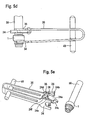
- figure 4a
- is a top view of the tool of
figure 3 with a housing offigure 2a , the tool being in its open position; - figure 4b
- corresponds to
figure 4a except for the tool being shown in its close position; - figure 5a
- is a part longitudinal cross-sectional view of the tool of
figure 3 corresponding with the housingfigure 2a ; - figures 5b
- is a view like
figure 5a with the pipe being inserted; - figure 5c
- is an enlargement of a part of
figure 5b ; - figure 5d
- is a top view of the tool and the pipe fitting of
figure 5b ; - figure 5e
- is a perspective view of the tool of
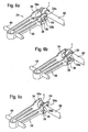
figure 3 and the pipe fitting arrangement offigures 2b ; - figures 6a to 6c
- demonstrate the attachment of the pipe fitting arrangement of
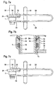
figure 2b to the tool offigure 3 ; - figures 7a to 7c
- demonstrate the removal of the pipe from the pipe fitting arrangement of
figure 2b with the help of the tool offigure 3 ; - figures 8a and 8b
- show side views of two different housings of a pipe fitting arrangement; and
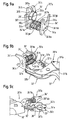
- figures 9a to 9c
- are prospecitve views of a tool of the invention provided in two parts, demonstrating the connection of said parts.
- As can be seen from
figure 2a , a pipe fitting arrangement comprises a housing I having afirst shoulder 2 with achamfer 3, aprojection 4 providing a second shoulder with achamfer 5b, a third shoulder with achamfer 5a next to afourth shoulder 6 and a foldedend 8 defining anopening 9. Between thefirst shoulder 2 and the second shoulder of the projection 4 a sealingring 10 is arranged, whereas between thefourth shoulder 6 and the folded end 8 agrip ring 12 is arranged. Thegrip ring 12 comprises firstexternal teeth 13 engaging thehousing 1 and secondinternal teeth 14 engaging a pipe as soon as having been inserted into the housing I through theopening 9 as shown infigure 2b , with the movement of thegrip ring 12 being limited by the third and fourth shoulder of theprojection 4. - Thus,
figure 2b is depicting a pipe fitting arrangement with apipe 50 ensuring a seal due to compressing the sealingring 10 while abutting in particular against theprojection 4, whereas retention of thepipe 50 within the housing I is provided by the engagement of theinternal teeth 14 of thegrip ring 12 on thepipe 50. Still further, a rotation of thepipe 50 relative to thehousing 1 is inhibited by the opposite orientation of the external andinternal teeth grip ring 12. Theinternal teeth 14 engaging thepipe 50 and theexternal teeth 13 engaging the housing I in addition ensure electric continuity between thepipe 50 and thehousing 1 as thegrip ring 12 is formed from a metal. - The
housing 1 is provided with a step like outer surface, namely afirst step 1a in the region of the sealingring 10 andgrip ring 12 comprising thefirst shoulder 2 and theprojection 4 and asecond step 1 b provided between thefirst shoulder 2 and a bend 1c of thehousing 1 serving as a limit stop for thepipe 50. - An insertion and release tool for such a pipe fitting arrangement is shown in
figure 3 . Accordingly, the pincers liketool 20 is provided with anopening 22 for the pipe fitting arrangement, a first engagement means for engaging thehousing 1 and/or thepipe 50 and a second engagement means for engaging the first engagement means and/or thehousing 1 as explained in detail in the following: - The first engagement means comprises a two
part ring 24 with afirst split 24a at one end of thetool 20, bordered by twoangled extensions further split 24e (as can be best seen infigure 5e ) opposite thefirst split 24a and a joint in form of apivot 24f next to thefurther split 24e (as can be best seen infigure 5e ) for facilitating the connection with the pipe 50 (as can be best seen infigures 6a to 6c ). Thering 24 also has afront face 24d for engaging the rolled-overend 8 of the housing I (as can be best seen infigure 5c ). Further, thering 24 is provided with aprojection 26 projecting from thefront face 24d in order to be inserted into thehousing 1 and being provided with two opposingsplits splits ring 24 and achamfer 26c (as can be best seen infigure 5c ) for facilitating the insertion between thepipe 50 and thehousing 1. - The second engagement means comprises a first holding means in form of a
jaw 34 for engaging thehousing 1 within anopening 34a and a second holding means in form of ajaw 36 for engaging the first engaging means. Thejaws U-shaped handle 30 provided withslots 32 along its two arms. Thesecond jaw 36 is also provided with tworecesses 36a for positioning a rubber O-ring 38 forming spring means, which also surrounds the two parts of thering 24 next to thefurther split 24e. Thering 24 is connected to thesecond jaw 36 by thepivot 24f. Infigure 3 thetool 20 is shown in its open position with a maximum distance between the twotool jaws slider bar 40 guided within theslots 32. Theslider bar 40 is provided withrecesses 42, 44 (as can be best seen infigure 4a ) in order to stay within theslots 32. - With respect to
figures 4a to 5e a method for forming the pipe fitting arrangement as shown infigure 2b with the help of thetool 20 as shown infigure 3 will be described: - The
tool 20 is put in its open position with theslider bar 40 being retracted as shown infigure 3 such that thehousing 1 can easily be placed within thetool 20, with thejaw 34 engaging thestep 1b as shown infigure 4a . - In the next step the
slider bar 40 is moved towards its opposite position in theslots 32 to bring thetool 20 in its close position securing thehousing 1 between itsjaws jaws ring 24, in particular itsfront face 24d, abuts against thehousing 1, seefigure 4b . Thus, when moving thetool 20 from its open position to its close position theprojection 26 is pushed into thehousing 1 and thereby forcing thegrip ring teeth 14 radially outward to engage thechamfer 5a of thefitting 1, seefigure 5a . -
Figure 5b illustrates the next step of operation, in which thepipe 50 is inserted through theopening 22 of thering 24 andprojection 26 into thehousing 1 without making contact with theteeth 14 and without requiring large pushing forces by a user (not shown). In fact, there is a clearance between thegrip ring 12 and the outer surface of thetube 50 due to the insertion of theprojection 26 as can be clearly seen fromfigure 5c . - To remove the
tool 20 upon completion of the pipe insertion theslider bar 40 is retracted in order to open thetool 20 as thehandle 30 springs back in its relaxed state, seefigure 5d . During opening thetool 20 theprojection 26 is retracted from the pipe fitting arrangement thereby allowing theteeth 14 to relax and finally engage thetube 50 as shown infigure 2b . - Finally, the
tool 20 can be removed from the pipe fitting arrangement by opening thesplit 24a as illustrated infigure 5e . - To release a previously fitted joint, that is the press fitting arrangement as shown in
figure 2b , by removing thepipe 50 the following sequence of steps can be conducted: - At the beginning the
tool 20 is aligned to thepipe 50 and thehousing 1, namely such that theslider bar 40 runs substantially parallel to thetube 50 while being in its retracted position such that thetool 20 is in its open position as shown infigure 6a . - In a next step the
tool 20 as such is pushed against thepipe 50 and thehousing 1 until theangled extensions ring 4 are engaged against thepipe 50, which in turn opens thesplit 24a as shown infigure 6b . - Pushing the
tool 20 further against thepipe 50 and thehousing 1 will finally result in thering 24 surrounding thepipe 50, with thering 24 being returned to its closed position having thesplit 24a closed by means of thespring 38. In this position thejaw 36 surrounds thepipe 50 within itsopening 36b and thejaw 34 engages thehousing 1 within itsopening 34a as shown infigure 6c . - The
slider bar 40 now has to be moved in the direction of the pipefitting arrangement tool 20 as shown infigure 7a . While closing thetool 20 theprojection 26 penetrates between thetube 50 and thehousing 1 and thereby forces theteeth 14 out of engagement with thepipe 50 as illustrated infigure 7b . - As soon as the
teeth 14 are no longer engaging thetube 50 the latter can be retracted out of thehousing 1 as shown infigure 7c . - Thus, the
tool 20 facilitates the connection and the release of a pipe fitting arrangement, is easy to handle and, simultaneously, avoids any damaging of the different components of the pipe fitting arrangement, in particular the pipe thereof, such that the pipe fitting arrangement, even after having been connected and released for several times, still is fluid tight. - The handling of the
tool 20 is more difficult in case the housing is formed in an elbow shape, like the housing 1' offigure 8a , although such a housing 1' is also provided with two steps 1'a, 1'b on its outside providing a shoulder 1'ab therebetween which can be engaged by thetool 20, in particular by itsjaw 34. The difficulty is a result of the length L1 between a free end of the housing 1' and its centre having to be sufficient to allow such an engagement. Therefore it is beneficial to provide an elbow shaped housing with a special geometry for thejaw 34 as shown infigure 8b . That is, thehousing 1" is still provided with twosteps 1"a and 1"b and in addition agroove 1"d between twoshoulders 1"aa provided instep 1"a. Thus, thegroove 1"d serves as a tool location groove facilitating the handling of atool 20 as thejaw 34 can be arranged with its inner edge within thegroove 1"d avoiding long housing lengths L1. With other words, the length L from the outer ends of thehousing 1" to its centre shown infigure 8b can be less than the corresponding length L1 shown infigure 8a and still allows for an easy handling of thetool 20. - A tool of the invention is described in the following with respect to
figures 9a to 9c . This second tool 20' differs from thefirst tool 20 in that it is provided in two parts with a first part 20'a comprising a first engagement means 24' and second engagement means 34', 36' and a second part 20'b comprising a handle 30'. The two parts 20'a and 20'b are connectable via a snap connection as will be described later on in detail such that in adaptation to a special housing and/or grip ring the first part 20'a can easily be exchanged. - The first engagement means comprises a two part ring 24' with two opposite splits 24'a and 24'e, two angled extensions 24'b, 24'c, a
front face 24'd and a projection 26'. The two parts of the ring 24' are interconnected via a spring 24'h as can be seen infigur 9b are connected and to the second engagement means 34', 36' each via a pivot 24'fa, 24'fb and a further spring 24'ga, 24'gb, with the pivots 24'fa, 24'fb extending through the second engagement means 34' and 36' through openings 34'ba, 34'bb, 36'bb. - The second engagement means comprises two holding means in form of jaws 34' and 36', said jaws 34' and 36' being interconnected via said pivots 24'fa, 24'fb and springs 24'ga, 24'gb and each do comprise an opening 34'a, 34'b for a pipe. In addition, said jaws 34', 36' each comprise an opening 34'c for receiving a projection 32'e of the second parts 20'b of the tool 20' in order to connect said two parts 20'a, 20'b.
- The handle 30' of the second part 20'b comprises two tong holds 31'a, 31'b and two gripper fingers 32'a, 32'b, with the gripper fingers 32'a, 32'b being moved towards each other when urging the tong holders 31'a, 31'b together. The gripper fingers 32'a, 32'b are provided at their free ends each with a snap connector 32'c, 32'd with a projection 32'e, only one of which being shown in
figure 9b , said two projections 32'e facing each other and are suited for engaging the recesses 34'c, only one of which being shown infigure 9c . - The tool 20' can be used for forming a pipe fitting arrangement as shown in
figure 2b as follows: - The tool 20' is assembled by attaching the second part 20'b to the first part 20'a via a snap connection. The springs 24'fa and 24'fb will then urge the gripper fingers 32'a, 32'b as well as the jaws 34', 36' away from each other such that the tool 20' is in its open position.
- In a next step a housing is inserted between the jaws 34', 36' such that the tool 20' can be brought in its closed position moving the jaws 34' and 36' towards each other against the force of the springs 24'fa, 24'fb via the gripper fingers 32'a, 32'b when urging the tong holder 31'b, 31'b towards each other. In the closed position of the tool 20' the projection 26' has entered the housing and forced teeth of a grip ring radially outwardly such that a pipe can be inserted into the openings 36'b, 22' and 34'a and, thus, into the housing.
- Then the tool 20' can be put in its open position again by removing the force applied to the tong holders 31'a, 31'b such that the springs 24'fa, 24'ga will urge the jaws 34', 36' as well as the gripper fingers 32'a, 32'b away from each other. During said movement the projection 26' will move out of the housing such that the teeth of the grip ring can move radialy inwardly until they grip the pipe.
- Finally, the tool 20' can be detached from the pipe fitting arrangement thus formed by opening the splits 26'b and 24'a and disassembling by detaching the connection between the first part 20'a and 20'b.
- The thus formed pipe fitting arrangement can be detached again by using the tool 20'c in its assembled form and open position namely by entering the pipe fitting arrangement into the first part 20'a such that the pipe will extend through the openings 34'a, 22', 36'b and the housing being arranged between the jaws 34' and 36', without the projection 26' having yet entered into the housing.
- As soon as the tool 20' is brought in its closed position by forcing the jaws 34', 36' towards each other against the force of the springs 24'fa, 24'f by urging the tong holders 31'a, 31'b towards each other, the teeth of the grip ring are again forced radially outwardly such that the pipe can easily be drawn out of the housing as well as the tool 20'.
- Finally, the housing can be removed out of connection with the tool 20', and even the connection between the two parts 20'a, 20'b of the tool 20' can be detached.
- Reference signs list
- 1, 1', 1"
- housing
- 1a, 1'a, 1"a, 1b, 1'b, 1"b
- step
- 1'ab, 1'aa
- shoulder
- 1c
- bend
- 1"d
- groove
- 2
- shoulder
- 3
- chamfer
- 4
- projection
- 5a, 5b
- chamfer
- 6
- shoulder
- 8
- folded end
- 9
- opening
- 10
- sealing ring
- 12
- grip ring
- 13
- external tooth
- 14
- internal tooth
- 20
- insertion and release tool
- 22
- opening
- 24
- ring
- 24a, 24'a
- split
- 24b, 24'b, 24c, 24'c
- angled extention
- 24d, 24'd
- front face
- 24e, 24'e
- split
- 24f, 24'fa, 24'fb
- pivot
- 24'ga, 24'gb
- spring
- 24'h
- spring
- 26, 26'
- projection
- 26a, 26'a, 26b, 26'b
- split
- 26c
- chamfer
- 30, 30'
- handle
- 31'a, 31'b
- tong hold
- 32
- slot
- 32'
- tong gripper
- 32'a, 32'b
- gripper finger
- 32'c, 32'd
- snap connector
- 32'e
- projection
- 34, 34'
- jaw
- 34a, 34'a
- opening
- 34'ba, 34'bb
- opening
- 34'c
- recess
- 36, 36'
- jaw
- 36a
- recess
- 36b, 36'b
- opening
- 36'bb
- opening
- 38
- O-ring
- 40
- slider bar
- 42
- recess
- 44
- recess
- 50
- pipe
- 100
- housing
- 102
- shoulder
- 103
- chamfer
- 104
- projection
- 105a, 105b
- chamfer
- 106
- shoulder
- 108
- rolled-over end
- 109
- opening
- 110
- sealing ring
- 112
- grip ring
- 114
- internal teeth
- 200
- release tool
- 202
- opening
- 204
- main body
- 204a
- split
- 204b
- recess
- 204c
- front face
- 206
- projection
- 206a
- cylindrical portion
- 206b
- chamfered portion
Claims (15)
- Tool (20') for a pipe fitting arrangement in which a pipe (50) is retainable arranged within a housing (1, 1', 1") by teeth (14) of a grip ring (12) placed within the housing (1, 1', 1"), the tool comprising:first engagement means (24', 26') for engaging at least partly around the pipe (50), said first engagement means (24', 26') having at least one part (26') adapted to enter the housing (1, 1', 1") around the pipe (50) in order to force the teeth (14) of the grip ring (12) out of engagement with the pipe (50);second engagement means (34', 36') for engaging the first engagement means (24', 26') as well as the housing (1, 1', 1") in order to locate the housing (1, 1', 1") relative to the tool (20'), in particular within the tool; anda handle (30') connected or connectable with the second engagement means ( 34', 36') and provided with actuation means,with the actuation means (24'fa, 24'fb, 31'a, 31'b) serving to urge the second engagement means (34', 36') either to engage the housing (1, 1', 1") or disengage the housing (1, 1', 1"), with the first engagement means (24', 26') being inserted into the housing (1, 1', 1") when the second engagement means (34', 36') engages the housing (1, 1', 1") as well as the first engagement means (24', 26') such that insertion of the pipe (50) into the housing (1, 1', 1") and removal of the pipe (50) from the housing (1, 1', 1") without the teeth (14) of the grip ring (12) touching the pipe (50) is ensured,wherein the first engagement means comprise a two-part ring (24'), characterised in that each of the two parts of the ring is connected to the second engagement means via a respective pivot (24'fa,24'fb) extending through the second engagement means and a spring (24'ga, 24'gb), such that the first engagement means are at least partly displaceable relative to the second engagement means (34', 36') along the pivots (24'fa, 24'fb).
- Tool according to claim 1, characterized in that
the first engagement means (24', 26') are connected to the second engagement means via at least one first joint comprising one of the pivots (24'fa,24'fb) and at least one first spring means (24'ga, 24'gb), wherein
the first spring means (24'ga, 24'gb) is comprised by the actuation means, (24'ga, 24'gb, 31'a, 31'b). - Tool according to claim 1 or 2, characterized in that
the first engagement means (24', 26') comprises a main body (24') having at least one face or shoulder (24'd), adapted to engage the end of the housing (1, 1', 1"), into which the pipe (50) is to be inserted or from which the pipe (50) is to be removed, and a first opening (22') for the pipe (50), said first opening (22') preferably being defined by the face or shoulder (24d') and/or being variable and/or adjustable, most preferably via the actuation means and/or second spring means (24'h), in particular the second spring means and the first spring means being formed together. - Tool according to claim 3, characterized in that
the main body (24') is deformable, preferably being formed at least partly from clastic or spring material, and/or can be opened, preferably by comprising at least one split (24'a, 24'e), most preferably two opposing splits. - Tool according to claim 3 or 4, characterized in that
the main body (24') comprises at least one, in particular angled, extension (24'b, 24'c) next to one split (24'a), preferably two such extensions one on each side of the split, to facilitate entering of the pipe (50) into the first engagement means (24', 26') through the split (24'a). - Tool according to claim 4 or 5, characterized in that
the main body (24') is formed by two halves being connected to each other, preferably via a third spring means (24'h), in particular the third spring means and the second spring means being formed together, and/or at least one second joint (24'fa, 24'fb), in particular in form of a pivot, arranged next to a split (24'e), in particular on both sides of the slit (24'e), most preferably the split (24'e) opposite the extension(s) (24'b, 24'c), in particular the second joint being identical to the first joint. - Toot according to one of the preceding claims, characterised in that
the ring has a tube like form, preferably having at lest one split (26'a, 26'b), most preferably two opposing splits, and/or is provided with a chamfer or tapering off towards its free end for facilitating its insertion into the housing (1, 1', 1"). - Tool according to one of the claims 3 to 7, characterized in that
the ring is formed as a projection of the main body (24') surrounding the first opening (22') at least partly. - Tool according to one of the preceding claims, characterized in that
the second engagement means (34', 36') comprises first holding means (34') for engagement with the housing (1, 1'. 1") as well as second holding means (36') for engagement with the first engagement means (24', 26'), the housing (1, 1', 1") being preferably locatable between the two holding means (34', 36') and/or the holding means (34', 36') being preferably moveable relative to each other via the actuation means (24'ga, 24'gb, 31'a, 31'b), in particular the first spring means (24'ga, 24'gb) being arranged between the two holding means (34', 36'). - Tool according to claim 9, characterized in that
the first holding means (34') comprises a substantially U-shaped first body, preferably in form of a first jaw, and/or
the second holding means (36') comprises a substantially U-shaped second body, preferably in form of a second jaw. - Tool according to one of the preceding claims, characterized in that
the handle (30') and the actuation means are formed as a pliers' and/or ratchet's handle and aeration means and/or comprise tong grippers (31'a, 31'b). - Tool according to one of the claims 9 to 11, characterized in that
the handle (30'), preferably in U-shape, is connected to the first and the second holding means, most preferably with one holding means provided at each free end, and/or the handle (30'), preferably comprising a pair of tong grippers (31'a, 31'b), is, in particular detachiably, connectable with the first and second holding means (34', 36'), preferably via gripper fingers (32'a, 32'b) and/or a snap connection. - Method for inserting a pipe into a housing for obtaining a pipe fitting arrangement and for removing the pipe out of the housing of a pipe fitting arrangement by making usage of a tool of one of the preceding claims, the housing having arranged therein a grip ring and a sealing ring in insertion direction, preferably the axial position of the grip ring and the sealing ring being restricted, in particular by internal projections or shoulders or bends of the housing.
- Method according to claim 13, characterized in that
the removal of the pipe from the housing with the teeth engaging the pipe comprises the following steps:i) locating the tool around the pipe fitting arrangement, preferably the tool being in its first open position with the second engagement means engaging the housing,ii) inserting the first engagement means into the housing thereby disengaging the teeth of the grip ring from the pipe by forcing them outwardly until the free ends thereof define an inner diameter larger than the outer diameter of the pipe, preferably by actuating the tool via the actuating means such that the tool comes into its second close position, andiii) removing the pipe from the pipe fitting arrangement and the first engagement means. - Method according to claim 14, characterized in that
step i) comprise(s) that the housing is aligned relative to the tool, preferably the lengitudinal axis of the housing being parallel to the longitudinal axis of the first, second and third opening, and the tool is pushed against the housing, preferably perpendicular to said longitudinal axes, preferably such that the split(s) of the first engagement means is/are opened when pushing the tool against the housing as soon as abutting against the pipe and closed when the first engagement means completely surrounds the pipe, preferably by the second spring means.
Priority Applications (1)
| Application Number | Priority Date | Filing Date | Title |
|---|---|---|---|
| EP08707448A EP2109517B8 (en) | 2007-02-01 | 2008-01-31 | Insertion and release tool for pipe fitting arrangement and method using such tool |
Applications Claiming Priority (3)
| Application Number | Priority Date | Filing Date | Title |
|---|---|---|---|
| EP07002188 | 2007-02-01 | ||
| PCT/EP2008/000759 WO2008092682A1 (en) | 2007-02-01 | 2008-01-31 | Insertion and release tool for pipe fitting arrangement and method using such tool |
| EP08707448A EP2109517B8 (en) | 2007-02-01 | 2008-01-31 | Insertion and release tool for pipe fitting arrangement and method using such tool |
Publications (3)
| Publication Number | Publication Date |
|---|---|
| EP2109517A1 EP2109517A1 (en) | 2009-10-21 |
| EP2109517B1 true EP2109517B1 (en) | 2011-11-09 |
| EP2109517B8 EP2109517B8 (en) | 2012-03-21 |
Family
ID=38089147
Family Applications (1)
| Application Number | Title | Priority Date | Filing Date |
|---|---|---|---|
| EP08707448A Not-in-force EP2109517B8 (en) | 2007-02-01 | 2008-01-31 | Insertion and release tool for pipe fitting arrangement and method using such tool |
Country Status (4)
| Country | Link |
|---|---|
| US (1) | US8424179B2 (en) |
| EP (1) | EP2109517B8 (en) |
| AT (1) | ATE532609T1 (en) |
| WO (1) | WO2008092682A1 (en) |
Cited By (1)
| Publication number | Priority date | Publication date | Assignee | Title |
|---|---|---|---|---|
| WO2022079563A1 (en) * | 2020-10-13 | 2022-04-21 | Tyco Fire Products Lp | Push-to-connect fitting systems and methods |
Families Citing this family (27)
| Publication number | Priority date | Publication date | Assignee | Title |
|---|---|---|---|---|
| US20100031486A1 (en) * | 2008-08-07 | 2010-02-11 | Catlin Bryan L | Hose quick release tool |
| IL214811A (en) * | 2011-08-24 | 2016-07-31 | Mordechai Eldar (Namdar) | Hand tool for inserting a variety of connectors into plastic irrigation piping |
| US20130075350A1 (en) * | 2011-09-28 | 2013-03-28 | Breakingpoint Systems, Inc. | Devices for facilitating installation and/or removal of components in an equipment rack |
| CA2806603C (en) * | 2013-02-25 | 2015-04-28 | Martin Gosselin | Tool and method for removing a pin from a door hinge |
| US10578234B2 (en) | 2013-05-02 | 2020-03-03 | Victaulic Company | Coupling having arcuate stiffness ribs |
| DK3397884T3 (en) | 2015-12-28 | 2020-08-03 | Victaulic Co Of America | ADAPTER CLUTCH |
| US10859190B2 (en) | 2016-05-16 | 2020-12-08 | Victaulic Company | Sprung coupling |
| US10605394B2 (en) | 2016-05-16 | 2020-03-31 | Victaulic Company | Fitting having tabbed retainer and observation apertures |
| US10533688B2 (en) | 2016-05-16 | 2020-01-14 | Victaulic Company | Coupling having tabbed retainer |
| US10414032B2 (en) | 2017-03-15 | 2019-09-17 | Conbraco Industries, Inc. | Push-to-connect fitting removal tool |
| US11260511B2 (en) * | 2017-09-20 | 2022-03-01 | Goodrich Corporation | Diaphragm coupling tools |
| CN107932364A (en) * | 2017-11-28 | 2018-04-20 | 国网浙江省电力公司绍兴供电公司 | A kind of GIS bayonet joints Special clamping instrument |
| CN109084108A (en) * | 2018-10-18 | 2018-12-25 | 青岛万合美联电器服务有限责任公司 | The quick coupling structure of convenient grafting |
| AU2020272576B2 (en) * | 2019-04-12 | 2023-08-24 | Oetiker Tool Company | Tool for disassembling connectors |
| CN210372464U (en) * | 2019-07-02 | 2020-04-21 | 台州爱伦阀门有限公司 | Quick connector |
| US11781683B2 (en) | 2019-11-15 | 2023-10-10 | Victaulic Company | Shrouded coupling |
| EP3842678A1 (en) * | 2019-12-26 | 2021-06-30 | Hsin Cheng Kuo | Tube connector |
| PL3871840T3 (en) | 2020-02-28 | 2022-05-30 | Ovh | Release tool for use with a push-fit valve |
| US12471942B2 (en) | 2020-12-02 | 2025-11-18 | Coloplast A/S | Tool adapted to connect tubing of an implantable penile prosthesis |
| USD965142S1 (en) | 2020-12-29 | 2022-09-27 | Coloplast A/S | Penile prosthesis tubing connector tool |
| CN113090868A (en) * | 2021-03-05 | 2021-07-09 | 福建晟扬管道科技有限公司 | High-strength PE (polyethylene) pressure charging pipe and using method thereof |
| USD1002845S1 (en) | 2021-12-01 | 2023-10-24 | Coloplast A/S | Penile prosthesis tubing connector tool |
| CN114012409A (en) * | 2021-12-20 | 2022-02-08 | 中国船舶重工集团公司第七一一研究所 | Dismounting device, and cooling water pipe mounting method and dismounting method thereof |
| CN117086588B (en) * | 2023-09-01 | 2025-09-26 | 中国联合工程有限公司 | Automatic tube threading machine for tubular heat exchanger and tube threading method thereof |
| US20250332699A1 (en) * | 2024-04-24 | 2025-10-30 | Greg Schneider | Plier apparatus |
| CN118664284A (en) * | 2024-06-07 | 2024-09-20 | 一汽丰田汽车有限公司 | Auxiliary tool and method for vertical installation of oil pipe |
| TWI905058B (en) * | 2025-04-29 | 2025-11-11 | 寶昌金屬工業有限公司 | Disassembly tool |
Family Cites Families (46)
| Publication number | Priority date | Publication date | Assignee | Title |
|---|---|---|---|---|
| CH649145A5 (en) | 1981-02-03 | 1985-04-30 | Contraves Ag | CONNECTOR PIPE CONNECTION. |
| DE3232367A1 (en) | 1982-08-31 | 1984-03-01 | Friedrich Deckel AG, 8000 München | Device for connecting a hydraulic clamping device arranged on a work pallet |
| US4586734A (en) | 1982-12-08 | 1986-05-06 | General Industries, Inc. | Pipe joint assembly |
| NL8204763A (en) | 1982-12-08 | 1984-07-02 | Johannes Antony De Waal | Large pipe or rod coupling mechanism - has collar with widened muff, incorporating packing with tilting ring for securing pipe against sliding |
| DE3322202C2 (en) | 1983-06-21 | 1986-11-20 | Helmut 7518 Bretten Hackel | Device for assembling or releasing a non-positive and form-fitting pipe plug connection |
| CH665700A5 (en) | 1984-07-10 | 1988-05-31 | Cejn Ag | DETACHABLE SLEEVE PIPE CONNECTION. |
| US5484011A (en) * | 1986-12-19 | 1996-01-16 | Applied Materials, Inc. | Method of heating and cooling a wafer during semiconductor processing |
| US5120153A (en) | 1988-11-07 | 1992-06-09 | Vassallo Research And Development Corp. | Fitting socket with integral reinforcing ring |
| GB2249367A (en) | 1990-09-18 | 1992-05-06 | Push Lok | Push fit pipe coupling |
| DE4137396A1 (en) | 1991-11-14 | 1993-05-19 | Raymond A & Cie | DETACHABLE CONNECTOR FOR SEMI-RIGID TUBES |
| IT1259568B (en) | 1992-04-30 | 1996-03-20 | Bertoldo & C Srl | CONNECTION JOINT FOR METAL TUBES |
| JPH05346191A (en) | 1992-06-15 | 1993-12-27 | Tube Forming:Kk | Tube joint |
| US5273588A (en) * | 1992-06-15 | 1993-12-28 | Materials Research Corporation | Semiconductor wafer processing CVD reactor apparatus comprising contoured electrode gas directing means |
| US5356476A (en) * | 1992-06-15 | 1994-10-18 | Materials Research Corporation | Semiconductor wafer processing method and apparatus with heat and gas flow control |
| US5444217A (en) * | 1993-01-21 | 1995-08-22 | Moore Epitaxial Inc. | Rapid thermal processing apparatus for processing semiconductor wafers |
| US5540821A (en) * | 1993-07-16 | 1996-07-30 | Applied Materials, Inc. | Method and apparatus for adjustment of spacing between wafer and PVD target during semiconductor processing |
| US5458379A (en) | 1993-11-05 | 1995-10-17 | Koganei Corporation | Valve-coupling assembly |
| US5518276A (en) | 1994-09-16 | 1996-05-21 | Bundy Corporation | Quick connector with pull back verification method |
| GB9507466D0 (en) | 1995-04-11 | 1995-05-31 | Imi Yorkshire Fittings | Improvements relating to releasable push-fit pipe couplings |
| US5830277A (en) * | 1995-05-26 | 1998-11-03 | Mattson Technology, Inc. | Thermal processing system with supplemental resistive heater and shielded optical pyrometry |
| GB2317212B (en) | 1995-07-07 | 1999-10-13 | Marley Extrusions | Push-fit tube couplings |
| US6093252A (en) * | 1995-08-03 | 2000-07-25 | Asm America, Inc. | Process chamber with inner support |
| US5695224A (en) | 1995-08-14 | 1997-12-09 | The Rovac Corporation | Pipe joint assembly |
| US5570910A (en) | 1995-08-18 | 1996-11-05 | Aeroquip Corporation | Coupling assembly |
| US6133550A (en) * | 1996-03-22 | 2000-10-17 | Sandia Corporation | Method and apparatus for thermal processing of semiconductor substrates |
| US5722702A (en) | 1996-04-12 | 1998-03-03 | Arnco Corporation | Plastic pipe compression coupler |
| WO1999023691A2 (en) * | 1997-11-03 | 1999-05-14 | Asm America, Inc. | Improved low mass wafer support system |
| US5971445A (en) | 1997-11-10 | 1999-10-26 | Pilot Industries, Inc. | Quick connect coupling with improved retainer |
| WO1999043978A1 (en) | 1998-02-28 | 1999-09-02 | Linkindex Limited | Pipe connection system |
| US6296711B1 (en) * | 1998-04-14 | 2001-10-02 | Cvd Systems, Inc. | Film processing system |
| DE10119047B4 (en) * | 2000-04-21 | 2010-12-09 | Tokyo Electron Ltd. | Thermal processing device and thermal processing method |
| DE20020052U1 (en) | 2000-11-25 | 2001-03-15 | Festo AG & Co, 73734 Esslingen | Connection device for a fluid line |
| US6913292B2 (en) | 2001-01-19 | 2005-07-05 | Victaulic Company Of America | Mechanical pipe coupling derived from a standard fitting |
| US7500699B2 (en) | 2001-01-19 | 2009-03-10 | Victaulic Company | Clamping mechanical pipe coupling derived from a standard fitting |
| GB0214971D0 (en) | 2002-06-28 | 2002-08-07 | Melimatic Ltd | Pipe fittings |
| US6818864B2 (en) * | 2002-08-09 | 2004-11-16 | Asm America, Inc. | LED heat lamp arrays for CVD heating |
| US6788991B2 (en) * | 2002-10-09 | 2004-09-07 | Asm International N.V. | Devices and methods for detecting orientation and shape of an object |
| USD483441S1 (en) | 2002-12-16 | 2003-12-09 | Victaulic Company Of America | Pipe coupling |
| FR2860572B1 (en) | 2003-10-02 | 2005-12-16 | Comap | DISASSEMBLY DEVICE FOR INSTANT CONNECTION |
| GB0411099D0 (en) | 2004-05-19 | 2004-06-23 | Oystertec Plc | Pipe fitting |
| USD517665S1 (en) | 2004-08-20 | 2006-03-21 | Victaulic Company | Pipe coupling |
| TWM269152U (en) | 2004-09-14 | 2005-07-01 | Auto Skill Ind Co Ltd | Tube-removing auxiliary device |
| US20060125236A1 (en) | 2004-12-15 | 2006-06-15 | Victaulic Company Of America | Retainer with inward projections |
| DE202005001100U1 (en) | 2005-01-25 | 2005-03-17 | Hummel Anton Verwaltung | Connecting system for pipes comprises sleeve, locking washer and thrust ring, union nut then being fitted and washer having sloping claws pressed against pipe when system is fastened together |
| DE202005008125U1 (en) * | 2005-05-24 | 2006-10-05 | Herrle, Richard | Pressing tool, press ring and pressing tongs |
| KR100898979B1 (en) * | 2007-08-08 | 2009-05-25 | 주식회사 에이디피엔지니어링 | Substrate lift device |
-
2008
- 2008-01-31 EP EP08707448A patent/EP2109517B8/en not_active Not-in-force
- 2008-01-31 AT AT08707448T patent/ATE532609T1/en active
- 2008-01-31 US US12/525,527 patent/US8424179B2/en active Active
- 2008-01-31 WO PCT/EP2008/000759 patent/WO2008092682A1/en not_active Ceased
Cited By (2)
| Publication number | Priority date | Publication date | Assignee | Title |
|---|---|---|---|---|
| WO2022079563A1 (en) * | 2020-10-13 | 2022-04-21 | Tyco Fire Products Lp | Push-to-connect fitting systems and methods |
| US12215812B2 (en) | 2020-10-13 | 2025-02-04 | Tyco Fire Products Lp | Push-to-connect fitting systems and methods |
Also Published As
| Publication number | Publication date |
|---|---|
| WO2008092682A1 (en) | 2008-08-07 |
| US8424179B2 (en) | 2013-04-23 |
| ATE532609T1 (en) | 2011-11-15 |
| US20100088869A1 (en) | 2010-04-15 |
| WO2008092682B1 (en) | 2008-10-02 |
| EP2109517A1 (en) | 2009-10-21 |
| EP2109517B8 (en) | 2012-03-21 |
Similar Documents
| Publication | Publication Date | Title |
|---|---|---|
| EP2109517B8 (en) | Insertion and release tool for pipe fitting arrangement and method using such tool | |
| US20080238088A1 (en) | Method for assembling and disassembling a pipe fitting arrangement with a tool and such a tool | |
| EP3375572B1 (en) | Push-to-connect fitting removal tool | |
| US10273996B2 (en) | Clamp for sanitary fitting | |
| JP4290364B2 (en) | Improved gripper for handling preforms | |
| US20110072593A1 (en) | Crimping Pliers | |
| CN110856909B (en) | Pressing or crimping pliers | |
| CA2276121A1 (en) | Self-adjusting pliers | |
| US20100170090A1 (en) | Coaxial cable installation tool | |
| CN113677482A (en) | Tools for removing connectors | |
| US5253408A (en) | Extraction tool | |
| EA004366B1 (en) | Hand tool for disconnection of couplings | |
| US4769891A (en) | Hand tool for tube fittings | |
| US11999033B2 (en) | Drain cleaner cable decoupler tool | |
| US5582084A (en) | Extension locking pliers | |
| US20220371164A1 (en) | Tool and associated method for temporary fastener placement | |
| US4021922A (en) | Orthodontic plier-type tool | |
| CN112621586A (en) | Clamp for releasing a line connection | |
| CN218747161U (en) | Spring expansion pliers for shaft | |
| CN220223526U (en) | Portable tool for quick opening and closing cover of PCR eight-joint pipe | |
| EP4458514A1 (en) | Rapid approach system for hand tools and gripping pliers | |
| CN220512881U (en) | A kind of clamp removal pliers | |
| CN115568627B (en) | Clamp type cigarette taking device | |
| RU217342U1 (en) | LC optical connector extraction tool | |
| CN216543070U (en) | Pipe removing device for internal pipe bending of air pipe connector |
Legal Events
| Date | Code | Title | Description |
|---|---|---|---|
| PUAI | Public reference made under article 153(3) epc to a published international application that has entered the european phase |
Free format text: ORIGINAL CODE: 0009012 |
|
| 17P | Request for examination filed |
Effective date: 20090824 |
|
| AK | Designated contracting states |
Kind code of ref document: A1 Designated state(s): AT BE BG CH CY CZ DE DK EE ES FI FR GB GR HR HU IE IS IT LI LT LU LV MC MT NL NO PL PT RO SE SI SK TR |
|
| DAX | Request for extension of the european patent (deleted) | ||
| 17Q | First examination report despatched |
Effective date: 20100917 |
|
| GRAP | Despatch of communication of intention to grant a patent |
Free format text: ORIGINAL CODE: EPIDOSNIGR1 |
|
| GRAS | Grant fee paid |
Free format text: ORIGINAL CODE: EPIDOSNIGR3 |
|
| GRAA | (expected) grant |
Free format text: ORIGINAL CODE: 0009210 |
|
| AK | Designated contracting states |
Kind code of ref document: B1 Designated state(s): AT BE BG CH CY CZ DE DK EE ES FI FR GB GR HR HU IE IS IT LI LT LU LV MC MT NL NO PL PT RO SE SI SK TR |
|
| REG | Reference to a national code |
Ref country code: GB Ref legal event code: FG4D |
|
| REG | Reference to a national code |
Ref country code: CH Ref legal event code: EP |
|
| REG | Reference to a national code |
Ref country code: IE Ref legal event code: FG4D |
|
| RAP2 | Party data changed (patent owner data changed or rights of a patent transferred) |
Owner name: CONEX UNIVERSAL LIMITED |
|
| REG | Reference to a national code |
Ref country code: DE Ref legal event code: R096 Ref document number: 602008011253 Country of ref document: DE Effective date: 20120105 |
|
| REG | Reference to a national code |
Ref country code: SE Ref legal event code: TRGR |
|
| REG | Reference to a national code |
Ref country code: NL Ref legal event code: T3 |
|
| LTIE | Lt: invalidation of european patent or patent extension |
Effective date: 20111109 |
|
| PG25 | Lapsed in a contracting state [announced via postgrant information from national office to epo] |
Ref country code: IS Free format text: LAPSE BECAUSE OF FAILURE TO SUBMIT A TRANSLATION OF THE DESCRIPTION OR TO PAY THE FEE WITHIN THE PRESCRIBED TIME-LIMIT Effective date: 20120309 Ref country code: NO Free format text: LAPSE BECAUSE OF FAILURE TO SUBMIT A TRANSLATION OF THE DESCRIPTION OR TO PAY THE FEE WITHIN THE PRESCRIBED TIME-LIMIT Effective date: 20120209 Ref country code: LT Free format text: LAPSE BECAUSE OF FAILURE TO SUBMIT A TRANSLATION OF THE DESCRIPTION OR TO PAY THE FEE WITHIN THE PRESCRIBED TIME-LIMIT Effective date: 20111109 |
|
| PG25 | Lapsed in a contracting state [announced via postgrant information from national office to epo] |
Ref country code: GR Free format text: LAPSE BECAUSE OF FAILURE TO SUBMIT A TRANSLATION OF THE DESCRIPTION OR TO PAY THE FEE WITHIN THE PRESCRIBED TIME-LIMIT Effective date: 20120210 Ref country code: LV Free format text: LAPSE BECAUSE OF FAILURE TO SUBMIT A TRANSLATION OF THE DESCRIPTION OR TO PAY THE FEE WITHIN THE PRESCRIBED TIME-LIMIT Effective date: 20111109 Ref country code: SI Free format text: LAPSE BECAUSE OF FAILURE TO SUBMIT A TRANSLATION OF THE DESCRIPTION OR TO PAY THE FEE WITHIN THE PRESCRIBED TIME-LIMIT Effective date: 20111109 Ref country code: PT Free format text: LAPSE BECAUSE OF FAILURE TO SUBMIT A TRANSLATION OF THE DESCRIPTION OR TO PAY THE FEE WITHIN THE PRESCRIBED TIME-LIMIT Effective date: 20120309 Ref country code: BE Free format text: LAPSE BECAUSE OF FAILURE TO SUBMIT A TRANSLATION OF THE DESCRIPTION OR TO PAY THE FEE WITHIN THE PRESCRIBED TIME-LIMIT Effective date: 20111109 Ref country code: HR Free format text: LAPSE BECAUSE OF FAILURE TO SUBMIT A TRANSLATION OF THE DESCRIPTION OR TO PAY THE FEE WITHIN THE PRESCRIBED TIME-LIMIT Effective date: 20111109 Ref country code: PL Free format text: LAPSE BECAUSE OF FAILURE TO SUBMIT A TRANSLATION OF THE DESCRIPTION OR TO PAY THE FEE WITHIN THE PRESCRIBED TIME-LIMIT Effective date: 20111109 |
|
| PG25 | Lapsed in a contracting state [announced via postgrant information from national office to epo] |
Ref country code: CY Free format text: LAPSE BECAUSE OF FAILURE TO SUBMIT A TRANSLATION OF THE DESCRIPTION OR TO PAY THE FEE WITHIN THE PRESCRIBED TIME-LIMIT Effective date: 20111109 |
|
| PG25 | Lapsed in a contracting state [announced via postgrant information from national office to epo] |
Ref country code: CZ Free format text: LAPSE BECAUSE OF FAILURE TO SUBMIT A TRANSLATION OF THE DESCRIPTION OR TO PAY THE FEE WITHIN THE PRESCRIBED TIME-LIMIT Effective date: 20111109 Ref country code: SK Free format text: LAPSE BECAUSE OF FAILURE TO SUBMIT A TRANSLATION OF THE DESCRIPTION OR TO PAY THE FEE WITHIN THE PRESCRIBED TIME-LIMIT Effective date: 20111109 Ref country code: DK Free format text: LAPSE BECAUSE OF FAILURE TO SUBMIT A TRANSLATION OF THE DESCRIPTION OR TO PAY THE FEE WITHIN THE PRESCRIBED TIME-LIMIT Effective date: 20111109 Ref country code: EE Free format text: LAPSE BECAUSE OF FAILURE TO SUBMIT A TRANSLATION OF THE DESCRIPTION OR TO PAY THE FEE WITHIN THE PRESCRIBED TIME-LIMIT Effective date: 20111109 Ref country code: BG Free format text: LAPSE BECAUSE OF FAILURE TO SUBMIT A TRANSLATION OF THE DESCRIPTION OR TO PAY THE FEE WITHIN THE PRESCRIBED TIME-LIMIT Effective date: 20120209 |
|
| PG25 | Lapsed in a contracting state [announced via postgrant information from national office to epo] |
Ref country code: MC Free format text: LAPSE BECAUSE OF NON-PAYMENT OF DUE FEES Effective date: 20120131 Ref country code: IT Free format text: LAPSE BECAUSE OF FAILURE TO SUBMIT A TRANSLATION OF THE DESCRIPTION OR TO PAY THE FEE WITHIN THE PRESCRIBED TIME-LIMIT Effective date: 20111109 Ref country code: RO Free format text: LAPSE BECAUSE OF FAILURE TO SUBMIT A TRANSLATION OF THE DESCRIPTION OR TO PAY THE FEE WITHIN THE PRESCRIBED TIME-LIMIT Effective date: 20111109 |
|
| REG | Reference to a national code |
Ref country code: CH Ref legal event code: PL |
|
| PLBE | No opposition filed within time limit |
Free format text: ORIGINAL CODE: 0009261 |
|
| STAA | Information on the status of an ep patent application or granted ep patent |
Free format text: STATUS: NO OPPOSITION FILED WITHIN TIME LIMIT |
|
| 26N | No opposition filed |
Effective date: 20120810 |
|
| REG | Reference to a national code |
Ref country code: IE Ref legal event code: MM4A |
|
| PG25 | Lapsed in a contracting state [announced via postgrant information from national office to epo] |
Ref country code: CH Free format text: LAPSE BECAUSE OF NON-PAYMENT OF DUE FEES Effective date: 20120131 Ref country code: LI Free format text: LAPSE BECAUSE OF NON-PAYMENT OF DUE FEES Effective date: 20120131 |
|
| REG | Reference to a national code |
Ref country code: AT Ref legal event code: MK05 Ref document number: 532609 Country of ref document: AT Kind code of ref document: T Effective date: 20111109 |
|
| REG | Reference to a national code |
Ref country code: DE Ref legal event code: R097 Ref document number: 602008011253 Country of ref document: DE Effective date: 20120810 |
|
| PG25 | Lapsed in a contracting state [announced via postgrant information from national office to epo] |
Ref country code: AT Free format text: LAPSE BECAUSE OF FAILURE TO SUBMIT A TRANSLATION OF THE DESCRIPTION OR TO PAY THE FEE WITHIN THE PRESCRIBED TIME-LIMIT Effective date: 20111109 Ref country code: IE Free format text: LAPSE BECAUSE OF NON-PAYMENT OF DUE FEES Effective date: 20120131 |
|
| PG25 | Lapsed in a contracting state [announced via postgrant information from national office to epo] |
Ref country code: ES Free format text: LAPSE BECAUSE OF FAILURE TO SUBMIT A TRANSLATION OF THE DESCRIPTION OR TO PAY THE FEE WITHIN THE PRESCRIBED TIME-LIMIT Effective date: 20120220 |
|
| PG25 | Lapsed in a contracting state [announced via postgrant information from national office to epo] |
Ref country code: FI Free format text: LAPSE BECAUSE OF FAILURE TO SUBMIT A TRANSLATION OF THE DESCRIPTION OR TO PAY THE FEE WITHIN THE PRESCRIBED TIME-LIMIT Effective date: 20111109 |
|
| PG25 | Lapsed in a contracting state [announced via postgrant information from national office to epo] |
Ref country code: MT Free format text: LAPSE BECAUSE OF FAILURE TO SUBMIT A TRANSLATION OF THE DESCRIPTION OR TO PAY THE FEE WITHIN THE PRESCRIBED TIME-LIMIT Effective date: 20111109 |
|
| PG25 | Lapsed in a contracting state [announced via postgrant information from national office to epo] |
Ref country code: TR Free format text: LAPSE BECAUSE OF FAILURE TO SUBMIT A TRANSLATION OF THE DESCRIPTION OR TO PAY THE FEE WITHIN THE PRESCRIBED TIME-LIMIT Effective date: 20111109 |
|
| PGFP | Annual fee paid to national office [announced via postgrant information from national office to epo] |
Ref country code: NL Payment date: 20140110 Year of fee payment: 7 Ref country code: SE Payment date: 20140113 Year of fee payment: 7 Ref country code: DE Payment date: 20140129 Year of fee payment: 7 |
|
| PG25 | Lapsed in a contracting state [announced via postgrant information from national office to epo] |
Ref country code: LU Free format text: LAPSE BECAUSE OF NON-PAYMENT OF DUE FEES Effective date: 20120131 |
|
| PGFP | Annual fee paid to national office [announced via postgrant information from national office to epo] |
Ref country code: FR Payment date: 20140108 Year of fee payment: 7 |
|
| PGFP | Annual fee paid to national office [announced via postgrant information from national office to epo] |
Ref country code: GB Payment date: 20140129 Year of fee payment: 7 |
|
| PG25 | Lapsed in a contracting state [announced via postgrant information from national office to epo] |
Ref country code: HU Free format text: LAPSE BECAUSE OF FAILURE TO SUBMIT A TRANSLATION OF THE DESCRIPTION OR TO PAY THE FEE WITHIN THE PRESCRIBED TIME-LIMIT Effective date: 20080131 |
|
| REG | Reference to a national code |
Ref country code: DE Ref legal event code: R119 Ref document number: 602008011253 Country of ref document: DE |
|
| REG | Reference to a national code |
Ref country code: NL Ref legal event code: V1 Effective date: 20150801 |
|
| GBPC | Gb: european patent ceased through non-payment of renewal fee |
Effective date: 20150131 |
|
| REG | Reference to a national code |
Ref country code: SE Ref legal event code: EUG |
|
| PG25 | Lapsed in a contracting state [announced via postgrant information from national office to epo] |
Ref country code: NL Free format text: LAPSE BECAUSE OF NON-PAYMENT OF DUE FEES Effective date: 20150801 |
|
| PG25 | Lapsed in a contracting state [announced via postgrant information from national office to epo] |
Ref country code: GB Free format text: LAPSE BECAUSE OF NON-PAYMENT OF DUE FEES Effective date: 20150131 Ref country code: DE Free format text: LAPSE BECAUSE OF NON-PAYMENT OF DUE FEES Effective date: 20150801 |
|
| REG | Reference to a national code |
Ref country code: FR Ref legal event code: ST Effective date: 20150930 |
|
| PG25 | Lapsed in a contracting state [announced via postgrant information from national office to epo] |
Ref country code: FR Free format text: LAPSE BECAUSE OF NON-PAYMENT OF DUE FEES Effective date: 20150202 Ref country code: SE Free format text: LAPSE BECAUSE OF NON-PAYMENT OF DUE FEES Effective date: 20150201 |