EP2109266B1 - Verfahren und Einrichtungen zum installieren von Paketfiltern bei einer Datenübertragung - Google Patents
Verfahren und Einrichtungen zum installieren von Paketfiltern bei einer Datenübertragung Download PDFInfo
- Publication number
- EP2109266B1 EP2109266B1 EP09009986A EP09009986A EP2109266B1 EP 2109266 B1 EP2109266 B1 EP 2109266B1 EP 09009986 A EP09009986 A EP 09009986A EP 09009986 A EP09009986 A EP 09009986A EP 2109266 B1 EP2109266 B1 EP 2109266B1
- Authority
- EP
- European Patent Office
- Prior art keywords
- packet
- user equipment
- bearer
- level identification
- entity
- Prior art date
- Legal status (The legal status is an assumption and is not a legal conclusion. Google has not performed a legal analysis and makes no representation as to the accuracy of the status listed.)
- Active
Links
- 238000000034 method Methods 0.000 title claims abstract description 85
- 230000005540 biological transmission Effects 0.000 title claims description 26
- 238000004891 communication Methods 0.000 claims abstract description 57
- 238000012544 monitoring process Methods 0.000 claims abstract description 31
- 230000000977 initiatory effect Effects 0.000 claims description 35
- 238000012986 modification Methods 0.000 claims description 6
- 230000004048 modification Effects 0.000 claims description 6
- 238000004590 computer program Methods 0.000 abstract 1
- 230000006870 function Effects 0.000 description 38
- 230000011664 signaling Effects 0.000 description 32
- 238000013507 mapping Methods 0.000 description 10
- 238000012545 processing Methods 0.000 description 7
- 238000009434 installation Methods 0.000 description 6
- 238000011161 development Methods 0.000 description 5
- 238000010586 diagram Methods 0.000 description 5
- 238000001914 filtration Methods 0.000 description 4
- 230000004913 activation Effects 0.000 description 3
- 230000001960 triggered effect Effects 0.000 description 3
- 101100264195 Caenorhabditis elegans app-1 gene Proteins 0.000 description 2
- 238000013475 authorization Methods 0.000 description 2
- 230000008901 benefit Effects 0.000 description 2
- 230000004069 differentiation Effects 0.000 description 2
- 230000007246 mechanism Effects 0.000 description 2
- 230000003068 static effect Effects 0.000 description 2
- 230000008275 binding mechanism Effects 0.000 description 1
- 239000000872 buffer Substances 0.000 description 1
- 238000012790 confirmation Methods 0.000 description 1
- 230000001934 delay Effects 0.000 description 1
- 230000003111 delayed effect Effects 0.000 description 1
- 230000001419 dependent effect Effects 0.000 description 1
- 238000012806 monitoring device Methods 0.000 description 1
- 230000003287 optical effect Effects 0.000 description 1
- GOLXNESZZPUPJE-UHFFFAOYSA-N spiromesifen Chemical compound CC1=CC(C)=CC(C)=C1C(C(O1)=O)=C(OC(=O)CC(C)(C)C)C11CCCC1 GOLXNESZZPUPJE-UHFFFAOYSA-N 0.000 description 1
- 238000012546 transfer Methods 0.000 description 1
Images


Classifications
-
- H—ELECTRICITY
- H04—ELECTRIC COMMUNICATION TECHNIQUE
- H04L—TRANSMISSION OF DIGITAL INFORMATION, e.g. TELEGRAPHIC COMMUNICATION
- H04L47/00—Traffic control in data switching networks
- H04L47/70—Admission control; Resource allocation
- H04L47/80—Actions related to the user profile or the type of traffic
- H04L47/803—Application aware
-
- H—ELECTRICITY
- H04—ELECTRIC COMMUNICATION TECHNIQUE
- H04L—TRANSMISSION OF DIGITAL INFORMATION, e.g. TELEGRAPHIC COMMUNICATION
- H04L45/00—Routing or path finding of packets in data switching networks
- H04L45/38—Flow based routing
-
- H—ELECTRICITY
- H04—ELECTRIC COMMUNICATION TECHNIQUE
- H04L—TRANSMISSION OF DIGITAL INFORMATION, e.g. TELEGRAPHIC COMMUNICATION
- H04L45/00—Routing or path finding of packets in data switching networks
- H04L45/74—Address processing for routing
- H04L45/745—Address table lookup; Address filtering
-
- H—ELECTRICITY
- H04—ELECTRIC COMMUNICATION TECHNIQUE
- H04L—TRANSMISSION OF DIGITAL INFORMATION, e.g. TELEGRAPHIC COMMUNICATION
- H04L47/00—Traffic control in data switching networks
- H04L47/70—Admission control; Resource allocation
-
- H—ELECTRICITY
- H04—ELECTRIC COMMUNICATION TECHNIQUE
- H04L—TRANSMISSION OF DIGITAL INFORMATION, e.g. TELEGRAPHIC COMMUNICATION
- H04L47/00—Traffic control in data switching networks
- H04L47/70—Admission control; Resource allocation
- H04L47/80—Actions related to the user profile or the type of traffic
- H04L47/808—User-type aware
-
- H—ELECTRICITY
- H04—ELECTRIC COMMUNICATION TECHNIQUE
- H04L—TRANSMISSION OF DIGITAL INFORMATION, e.g. TELEGRAPHIC COMMUNICATION
- H04L47/00—Traffic control in data switching networks
- H04L47/70—Admission control; Resource allocation
- H04L47/82—Miscellaneous aspects
- H04L47/824—Applicable to portable or mobile terminals
-
- H—ELECTRICITY
- H04—ELECTRIC COMMUNICATION TECHNIQUE
- H04L—TRANSMISSION OF DIGITAL INFORMATION, e.g. TELEGRAPHIC COMMUNICATION
- H04L47/00—Traffic control in data switching networks
- H04L47/70—Admission control; Resource allocation
- H04L47/82—Miscellaneous aspects
- H04L47/825—Involving tunnels, e.g. MPLS
-
- H—ELECTRICITY
- H04—ELECTRIC COMMUNICATION TECHNIQUE
- H04W—WIRELESS COMMUNICATION NETWORKS
- H04W28/00—Network traffic management; Network resource management
- H04W28/16—Central resource management; Negotiation of resources or communication parameters, e.g. negotiating bandwidth or QoS [Quality of Service]
- H04W28/18—Negotiating wireless communication parameters
-
- H—ELECTRICITY
- H04—ELECTRIC COMMUNICATION TECHNIQUE
- H04W—WIRELESS COMMUNICATION NETWORKS
- H04W76/00—Connection management
- H04W76/10—Connection setup
-
- H—ELECTRICITY
- H04—ELECTRIC COMMUNICATION TECHNIQUE
- H04W—WIRELESS COMMUNICATION NETWORKS
- H04W76/00—Connection management
- H04W76/20—Manipulation of established connections
-
- H—ELECTRICITY
- H04—ELECTRIC COMMUNICATION TECHNIQUE
- H04W—WIRELESS COMMUNICATION NETWORKS
- H04W80/00—Wireless network protocols or protocol adaptations to wireless operation
- H04W80/04—Network layer protocols, e.g. mobile IP [Internet Protocol]
Definitions
- the present invention relates to a method for associating a data packet with a packet bearer in a user equipment of a communication network.
- Devices and software programs embodying the invention are also described.
- data packets need to be sent over a communication network between a user equipment and a further entity. Transmissions can be performed both in downlink and uplink direction and the further entity is often another user equipment, e.g. in a telephone call.
- the further entity may also be a service entity like a server which may send different packet flows for sound and video to the user equipment, e.g. in a streaming session, while the user equipment may also send packets to the further entity.
- the further entity can either be part of the communication network or it is able to exchange data packets with the network.
- the communication network can be a fixed or a mobile network. More than one network can be involved in the transmission, e.g. if the user equipment is located in a mobile network which is interfacing directly or via intermediate networks to a fixed network in which the further entity is located.
- Customary mobile networks comprise a core network with core network nodes, e.g. general packet radio service support nodes (GSN) like a serving general packet radio service support node (SGSN) or a gateway general packet radio service support node (GGSN).
- GSN general packet radio service support nodes
- SGSN serving general packet radio service support node
- GGSN gateway general packet radio service support node
- the core network nodes allow the exchange of data with external networks such as the Internet or mobile or fixed networks of other operators.
- customary mobile networks comprise one or more access networks with access network nodes for controlling the radio transmission to user equipment, commonly designated, e.g., as base station controllers, radio network controllers (RNC), Node B or base transceiver stations.
- access network nodes for controlling the radio transmission to user equipment, commonly designated, e.g., as base station controllers, radio network controllers (RNC), Node B or base transceiver stations.
- RNC radio network controllers
- Node B Node B
- Other implementations of the nodes and networks are possible, for example an enhanced GSN and an enhanced RNC which perform different parts of the SGSN functionality and thus allow omitting an SGSN.
- An operator may offer services to the subscribers that generate different types of packet traffic, which are all transmitted over the communication network.
- the requirements for the transmission differ significantly. For example, voice transmission requires low delay and jitter while a limited amount of errors can be acceptable. Streaming sessions using packet buffers typically allow higher delays and jitter and the receiver can generally also correct or hide errors. File transfer can often be performed as best-effort traffic but normally requires error-free data.
- operators may choose to offer different qualities of service (QoS) depending on the user subscription, i.e. they may choose to perform user differentiation. Accordingly, the provision of a defined quality of service is an important concept in the control of data traffic as described for example in technical specification 3GPP 23.107 V 6.3.0. of the 3 rd Generation Partnership Project "Quality of Service (QoS) concept and architecture".
- QoS qualities of service
- Different contexts define the quality of service relating to a data transmission involving nodes of a communication network and the user equipment.
- the user equipment and a core network node negotiate a PDP (Packet Data Protocol) context which specifies parameters for the transmission of data packets to and from the user equipment over a 3GPP bearer.
- PDP Packet Data Protocol
- Further contexts can be set up for bearers relating to different links between the further entity and the user equipment, e.g. a context for the radio bearer between an access node and the user equipment, which specifies the transmission parameters on the radio link. Packet flows between the further entity and the user equipment are then mapped to bearers associated with these contexts and forwarded accordingly.
- the bearer is associated with a PDP context.
- the PDP context is the granularity with which QoS can be provided, i.e. different PDP contexts can provide a different QoS.
- the mapping of packets onto PDP contexts is done in an edge node of the communication network, e.g. in the GGSN using downlink Traffic Flow Templates (TFT).
- TFT Traffic Flow Templates
- a TFT is a packet filter which defines rules that uniquely map incoming data packets onto a PDP context.
- the downlink TFT is part of the PDP context definition and can be configured to operate on a number of different parameters.
- IP source address of a data packet or the "Type of Service"-field (ToS) in the IP-header can be used to map packets onto a PDP context.
- the Session Management (SM) protocol is used to manage PDP Contexts.
- the user equipment requires information how to map data packets from an application to a bearer with the associated context.
- this functionality is not in the scope of the current 3GPP standards. Instead, it is defined proprietarily and can differ between vendors of user equipment.
- the user equipment has several PDP context templates, each with a different associated QoS.
- a connection manager provides a mapping for each application to one of the PDP context templates.
- the mapping is a static configuration which creates a binding in the connection manager and which is signaled to the user equipment, e.g. by an SMS.
- the user performs the configuration by visiting the web-site of an operator and entering the phone model he is using and which application he wants to configure, e.g. WAP or MMS.
- the application Upon initiation of a session, e.g., when making a call, the application communicates to the connection manager through a proprietary API (Application Programming Interface).
- the connection manager associates the data packets from the application with the configured PDP context and, if required, sets up the context.
- the identifiers and formats used in the configuration can be specific for each vendor. A system of the prior art is disclosed, for example, in International Application WO 02/067605 A1 .
- user equipment may consist of two entities, a terminal equipment (TE) and a mobile terminal (MT) which are logically and optionally also physically distinct.
- Applications are executed in the terminal equipment and data packets are exchanged over the mobile terminal with the mobile network.
- TE terminal equipment
- MT mobile terminal
- an interface between TE and MT would be required over which it is possible to convey the bearer requirements of the application.
- the binding of application and context is vendor specific in present user equipment, different interfaces would be required.
- the terminal equipment is for example a personal computer and the mobile terminal is a mobile network card, the computer may need to support different interfaces for different card vendors, leading to high complexity and cost.
- the invention is embodied in a method and a user equipment as described in the independent claims.
- Advantageous embodiments are described in the dependent claims.
- the proposed method associates a data packet with a packet bearer in a user equipment of a communication network.
- the data packet is sent in a data flow from an application function of the user equipment. Although the flow may comprise only a single data packet, typically a plurality of data packets is sent in the flow.
- the packet bearer is established with the user equipment to transmit the data packet over the communication network towards a further entity, for example to another user equipment or to a server.
- the establishment of the bearer can be triggered by the user equipment or by another entity in the communication network. The establishment can be performed at different times in relation to the other steps of the method as will be described below.
- the user equipment is adapted to establish different packet bearers. For example, the bearers may differ in the provided quality of service. Optionally, the user equipment may keep more than one bearer established simultaneously.
- the method identifies the flow with the data packet in a control entity of the communication network.
- a policy function of the control entity determines the packet bearer for association with said flow from the different packet bearers.
- the control entity is provided with operator policy rules to determine the selection of the determined bearers out of the different bearers which the user equipment is adapted to establish.
- the control entity can be for example a GSN or a PCRF (Policy and Charging Rules Function).
- a routing level identification of the further entity is determined. This determination can be performed in the control entity or in another entity of the network which forwards the routing level identification to the control entity.
- the routing level identification enables the forwarding of data packets to the further entity.
- the routing level identification can be part of and used in the identification of the flow.
- the user equipment is instructed to install a packet filter based on the routing level identification.
- the packet filter associates data packets comprising the routing level identification of the further entity with the determined packet bearer.
- the routing level identification is provided to the application function, for example in a signaling message originating from the further entity.
- the routing level identification is included into the data packet. Accordingly, the data packet is forwarded by the packet filter on the determined packet bearer.
- the proposed method allows a simple and flexible association of data packets to packet bearers which does not require a prior configuration of the association and can be established before, at or after the initiation of a data session.
- the proposed method provides a controlled way for the communication network, i.e., the operator of the network, for mapping data packets onto bearers in the uplink from the user equipment to a further entity and thus to provide differentiation between services and between users.
- the network can allow or forbid the mapping of selected flows to bearers in the user equipment by the policy function controlling the filter installation. For this purpose, the operator may specify policy rules.
- the method enables access agnostic application development, i.e., applications can be developed independently of the access network to which the user equipment is connected because only ubiquitous socket API functions are used. This simplifies the development of applications making the development less expensive.
- the routing level identification can be set by the application through the socket API. The method does not introduce new dedicated signals to install the uplink packet filter but reuses existing procedures for this purpose and can accordingly easily be implemented in existing
- Communication networks typically comprise a plurality of entities.
- the control entity receives the determined routing level identification from a monitoring entity and instructs the user equipment to install the packet filter.
- the monitoring entity and the control entity may be implemented as parts of a single device or in different devices.
- the monitoring entity can for example monitor a signaling for session establishment between the user equipment and the further entity or data packets sent during an established session between the user equipment and the further entity.
- the signaling for installing the filter and for session initiation have different receiving entities in the user equipment and will generally also be performed using different signaling protocols it is often not suitable to have a single entity for monitoring the session level messages and instructing the filter installation.
- an establishment of a communication session is initiated between the user equipment and the further entity by an initiation message.
- the initiation message comprises a session level identification of the further entity, e.g., in the format of a telephone number, a uniform resource locator (URL) or an e-mail address or any other session level identification.
- a monitoring entity is adapted to monitor messages sent between the user equipment and the further entity for establishing the session.
- the monitoring entity stores information related to the communication session.
- the monitoring entity can be a call state control function storing a state for initiated sessions.
- the monitoring entity may be associated with an entity for performing an address resolution of the session level identification for forwarding the initiation message to the further entity.
- the initiation message is forwarded towards the further entity using the session level identification.
- the monitoring entity then waits for a reply message related to the establishment of the communication session and determines the routing level identification of the further entity from the reply message. It is possible to receive several reply messages and the routing level identification can be determined from one or several reply messages.
- the reply message is forwarded to the user equipment and the session establishment is completed. This embodiment allows a simple implementation to obtain the required information and to determine the identification of the flow, especially for the originating side of the session.
- an establishment of a communication session between the further entity and the user equipment is initiated by an initiation message comprising a routing level identification of the further entity and a session level identification of the user equipment.
- a monitoring entity is adapted to receive the initiation message and to determine the routing level identification of the further entity from the initiation message.
- the initiation message is then forwarded towards the user equipment using the session level identification, and the session establishment is completed.
- initial data packets sent by the user equipment on a first bearer are inspected, for example in the control entity or in a monitoring entity.
- the first bearer can be for example a default bearer or it can be established according to one of the preceding embodiments described.
- the flow for association is identified from the inspected data packets, e.g., due to information in the packet header, the packet content or other parameters of the data packets.
- a second packet bearer is determined for association with said flow.
- the second bearer can then be established for the flow, a filter can be installed to associate the flow with an existing second bearer, or parameters of an existing bearer, e.g. the first bearer, may be modified for this purpose.
- the setup of the packet bearer is initiated by a request from a node in the communication network. This allows an improved control of the network operator over the transmission by the user equipment.
- the packet bearers differ in at least one associated item from a group comprising a quality of service, a charging tariff and an access point to which the packet is forwarded. Accordingly, the bearers can provide a different quality of service or may be charged differently or both and can be selected accordingly.
- the user equipment comprises an executing unit for executing the application function and a transmission unit for sending the data packet on the associated packet bearer.
- the executing unit and the transmission unit are embodied in the same device, for example in a mobile phone.
- the units can be logically distinct, i.e. they may have a specified interface like for example a mobile terminal and a terminal equipment according to 3GPP specifications.
- the user equipment comprises physically distinct devices, e.g. the transmission unit may be a UMTS card or a mobile phone while the executing unit is part of another device connectable to the transmission unit, for example a computer or a television set with a wired or wireless connection to the transmission unit.
- the data packet is an internet protocol IP data packet.
- IP data packet is an internet protocol IP data packet.
- Session initiation signaling can be performed using a session protocol which is based on the IP protocol. Suitable protocols are for example the session initiation protocol (SIP) or the real time streaming protocol (RTSP). Both can be used in conjunction with the session description protocol (SDP).
- SIP session initiation protocol
- RTSP real time streaming protocol
- the routing level identification of the further entity preferably comprises a destination address and/or destination port number, for example an IP address and an IP port number.
- the packet bearer can be established at different times before or during the described method. Often it is suitable to establish the bearer simultaneously with the filter installation. In another embodiment, the bearer is set up before installing the packet filter. It is also possible to establish the bearer prior to establishment of a communication session in which the data packets are sent. In these cases, the packet filter can be installed in a modification procedure of the packet bearer. This embodiment is advantageous if the time required for bearer establishment is long compared to the time for filter installation.
- the packet filter associates the data packet with the packet bearer based on at least one further parameter.
- the packet filter may evaluate further fields in the packet header, e.g. the source address, the source port number, further header fields like a differentiated services code point (DSCP), the protocol identification, or any combination of such parameters.
- DSCP differentiated services code point
- An advantageous communication network is adapted to perform any embodiment of the method as described above.
- a preferable control entity is adapted for a communication network with a user equipment.
- An application function of the user equipment is adapted to send a data packet in a data flow and a packet bearer can be established with the user equipment to transmit the data packet over the communication network towards a further entity.
- the user equipment is adapted to establish different packet bearers.
- the control entity comprises an input unit adapted to receive the flow with the data packet or information related to the flow. Accordingly, the control entity may be either part of the flow path or it may receive information related to the flow, e.g. source and destination, from another entity in the network.
- a processing unit of the control entity comprises an identification function adapted to identify the flow.
- a policy function is adapted to determine the packet bearer for association with said flow from the different packet bearers, e.g. according to rules specified by the operator of the network. As an example, the operator may specify that packets from a specific source or destination are forwarded on a bearer with specific parameters.
- the processing unit is adapted to determine a routing level identification of the further entity with a determination function. Typically, the processing unit determines the routing level identification from a message received from a further entity in the network.
- An output unit is adapted to instruct the user equipment to install a packet filter based on the routing level identification, the packet filter associating data packets comprising the routing level identification of the further entity with the determined packet bearer.
- the input and output unit may be embodied in a common input/output unit. It is also possible that the control entity instructs further nodes to perform the signaling.
- An advantageous monitoring entity is adapted for use in a communication network with a user equipment.
- An application function of the user equipment is adapted to send a data packet in a data flow.
- the packet bearer is established with the user equipment to transmit the data packet over the communication network towards a further entity, and the user equipment is adapted to establish different packet bearers.
- the monitoring entity comprises an input unit adapted to receive an initiation message comprising a session level identification of the further entity, the initiation message initiating an establishment of a communication session between the user equipment and the further entity.
- the monitoring entity is also adapted to receive a reply message to the initiation message.
- a processing unit of the monitoring entity is adapted to monitor the messages and to determine a routing level identification of the further entity from the initiation message or from the reply message.
- An output unit adapted to forward the initiation message towards the further entity using the session level identification and to forward the reply message to the user equipment.
- the monitoring entity is further adapted to forward the determined routing level identification to a control entity for instructing the user equipment to install a packet filter based on the routing level identification, wherein the packet filter associates data packets comprising the routing level identification of the further entity with the determined packet bearer.
- An advantageous monitoring entity comprises a memory for storing an information related to the communication session.
- the invention can also be embodied in a software program comprising code for performing the steps of the method relating to the device in which the program is executed. It is preferably executed in a control entity.
- An advantageous program for associating a data packet with a packet bearer in a user equipment is adapted for a communication network, in which the data packet is sent in a data flow from an application function of the user equipment.
- the packet bearer is established with the user equipment to transmit the data packet over the communication network towards a further entity.
- the user equipment is adapted to establish different packet bearers, a routing level identification is provided to the application function, and the routing level identification is included into the data packet. The latter steps may be performed during or after execution of the program.
- the program comprises program code for identifying the flow with the data packet in a control entity of the communication network. It determines the packet bearer for association with said flow from the different packet bearers. It determines also the routing level identification of the further entity, optionally from information received from another entity in the communication network.
- the program initiates an instruction to the user equipment to install a packet filter based on the routing level identification, wherein the packet filter associates data packets comprising the routing level identification of the further entity with the determined packet bearer.
- the program according to the invention is for example stored on a data carrier or loadable into a processing unit of a user equipment or a control device, e.g. as a sequence of signals.
- control entity the monitoring entity and the software program can be adapted to any embodiment of the method described above.
- Fig. 1 illustrates a quality of service concept in 3 rd generation mobile systems as specified in technical specification 3GPP 23.107 V 6.3.0. of the 3 rd Generation Partnership Project.
- Traffic comprising data packets is sent between a further entity (AF) and a user equipment comprising a terminal equipment (TE) and a mobile terminal (MT).
- the further entity (AF) may be a server which could be located in the operator's network or in an external network but it can be also another user equipment.
- the object of the concept is to provide a defined quality of service (QoS) on the application level using the bearer services of the underlying levels.
- Those bearer services are specified by contexts comprising attributes for defining the QoS of the respective bearer service.
- the quality of the end-to-end service on the application layer depends on the specifications of the underlying levels, the contexts of the bearer services need to be specified with respect to the required end-to-end quality of service.
- the TE/MT local bearer service forwards the data packets within the user equipment between the terminal equipment (TE) and the mobile terminal (MT).
- terminal equipment (TE) and the mobile terminal (MT) may be part of a single device or may be embodied in different devices utilizing communication via the TE/MT local bearer service.
- the data packets are received or sent over a radio link with the radio access network (RAN1) of the mobile network.
- the External Bearer Service is provided by another network which can also be a UMTS (Universal Mobile Telephony System) network, i.e. a network according to 3GPP specifications, another mobile network or a fixed network like a fixed communication system such as the Internet.
- the external bearer forwards data packets between the further entity (AF) and an edge node (CN-GW) of the core network of the mobile network.
- AF further entity
- CN-GW edge node
- the core network comprises also a core network node (CN1) which controls the forwarding of packets between core network and radio access network (RAN1).
- Edge node (CN-GW) and core network node (CN1) can be the same node.
- the data packet traffic through the mobile network is sent over a Radio Access Bearer Service between mobile terminal (MT) and core network node (CN1) and over a Core Network Bearer Service between Gateway node (CN-GW) and core network node (CN1).
- MT mobile terminal
- CN-GW Core Network Bearer Service
- CN-GW Core Network Bearer Service
- These Services are in turn provided by a Radio Bearer Service on the radio link between user equipment and radio access network (RAN1), a RAN Access Bearer Service between radio access network (RAN1) and core network node (CN1) and a Backbone Bearer Service within the core network.
- all services depend on different physical bearer services on the respective links, i.e. typically a plurality of contexts and services relate to individual links in a transmission.
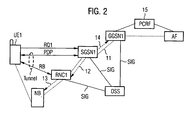
- FIG 2 shows an example of a transmission of data packets using the proposed method with involved contexts and nodes.
- a PDP context (PDP) is negotiated between the user equipment (UE1) and a core network node, here an SGSN (SGSN1). The transmission is later performed via core network node and access node or at least controlled by them.
- the dotted line 11 indicates a possible route on which the packets are forwarded in up-link and down-link direction between the user equipment (UE) and the further entity (AF).
- a control entity (PCRF) has interfaces to communicate with a GGSN (GGSN1) as edge node and with the further entity (AF).
- the set up of the PDP context can for example be initiated by a corresponding request (RQ1) from the user equipment to the SGSN. It is also possible that the network (e.g., the GGSN) requests the set up of the PDP context (PDP), for example by a message to the user equipment which then initiates the sending of a request (RQ1) to activate a PDP context.
- RQ1 request from the user equipment to the SGSN.
- the PDP context comprises attributes which define the quality of service for the packet transmission.
- the establishment of a radio bearer (RB) is typically included in the establishment of a PDP context.
- the SGSN (SGSN1) sends a request (12) for establishment of a radio bearer (RB) to an access node, in the example an RNC (RNC1).
- RNC1 radio resource control signaling
- the transmission of the data packets on the radio link to the user equipment is for example performed by a node B (NB) which is controlled by the RNC using radio resource control signaling (13). It is also possible to integrate the functionality of the node B and the RNC in a single node.
- the SGSN sends also a request (14) to an edge node of the core network, here a GGSN (GGSN1), for the establishment of a core network bearer.
- GGSN1 GGSN
- the configuration of the different nodes can be performed from an operation support system (OSS) over signaling links (SIG).
- OSS operation support system
- SIG signaling links
- Figure 3 illustrates the basic concept of the proposed method for the example of a UMTS network.
- a GGSN as edge node (EN2) and a Radio Access Network (RAN) provide two bearers with different characteristics denoted Bearer A and Bearer B.
- the bearers may differ in many different ways. Two examples of the characteristics could be the QoS associated to the bearers or the charging policy associated to data packets transmitted over the bearer.
- the GGSN comprises down link packet filters (DL PF) which map packet flows generated by different services onto the bearers.
- DL PF down link packet filters
- a packet flow is a group of data packets with the same source, destination, and protocol.
- IP flow consists of data packets with the same source address, source port, destination address, destination port, and protocol identification.
- a first service (Srv1) generates two application flows
- a second service (Srv2) generates one application flow which are mapped onto the bearers by the down link packet filters (DL PF).
- the data packets originating from the services require different bearers and are accordingly also indicated in broken and continuous lines, corresponding to the bearer to which they are forwarded by the down link packet filters (DL PF).
- the first application function App1 is executed in the user equipment (UE2) which consists of a personal computer as executing unit (EU2) and a mobile phone as transmission unit (TU2).
- the first application function App1 generates two data packet flows, each with characteristics which demand different treatment in the network. This is again indicated by broken and continuous outlines corresponding to the outlines of the bearer which shall be used. Also the data packets (DP, DP') are indicated in continuous and broken lines, corresponding to the respective bearer. Examples of applications which generate a plurality of packet flows are multimedia and presence applications which combine e.g. a voice over IP service with other services such as video, chat, whiteboard and file sharing.
- a second application function App2 generates only a single data packet flow.
- the proposed method provides a mechanism for a mapping between the data packet flows and the bearers.
- the example describes a split user equipment with distinct devices the method is also applicable if the applications are executed on a device comprising both the executing unit and the transmission unit.
- the executing unit marks the data packets of the different application flows with the destination for which they are intended. In the example, this is achieved by the network instructing the executing unit to mark the different application flows with a particular combination of a destination IP address and destination port number through application-layer signaling using, e.g., SIP/SDP.
- application-layer signaling using, e.g., SIP/SDP.
- the functionality of signaling a routing level identification may be part of any session-level protocol.
- UL Packet Filters are established in the transmission unit and provide a mapping of the packets onto the different bearers to which the filters are associated.
- the filters use the routing level identification, e.g. the combination of destination IP address and port number for the mapping of packets onto the bearers. It is possible that other parameters are checked in addition by the packet filters. For example, further filtering can be based on the source address, the source port number, a differentiated services code point (DSCP), the protocol identification, further fields in the IP header or any combination of such parameters. This enables a finer granularity of the mapping.
- DSCP differentiated services code point
- the network can control the association of an uplink data packet with one of multiple packet bearers in a user equipment of a communication network, wherein the uplink data packet originates from an application function, and the packet bearer is established between the user equipment and the network infrastructure.
- the method identifies a flow of uplink data packets that is subject to control and determines the packet bearer to be associated with said flow of uplink packets. This determination is performed in the network.
- the routing level identification of said flow of uplink data packets is also identified in the network.
- the association of the routing level identification with the determined packet bearer is provided to the user equipment.
- the uplink data packet is associated with the determined packet bearer in the user equipment based on the association provided from the network.
- a preferable routing level identification is the IP flow 5-tuple or a subset of the IP flow 5-tuple, in particular the destination IP address and destination port number.
- the identification of the flow of uplink data packets and the related routing level identification is preferably based on analyzing flow descriptions included in session level signaling messages sent between the application function and the receiving application entity, e.g. based on protocols using SDP, like SIP or RTSP.
- the routing level identification can be included in a session level signaling message destined to said application function, in the form of the destination IP address and port number to be used in uplink data packets from the application function.
- the provision of the association of routing level identification with a packet bearer can be done at the establishment of the packet bearer. Alternatively, the provision can be done for a packet bearer that has been established previously.
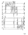
- FIGS 4 - 6 show examples of signaling sequences for installing a packet filter in a user equipment during the setting up of a SIP based session in a 3GPP communication network. Similar sequences would also apply to RTSP/SDP sessions. It is assumed in the examples that the PDP context used to carry the SIP signaling is already established when the session is initiated. The preceding signaling for setting up this PDP context is therefore not shown. PDP contexts can for example be set up according to a request from the network, e.g. a Secondary Network Requested PDP Context Activation (SNRPCA).
- SNRPCA Secondary Network Requested PDP Context Activation
- SNRPCA signaling can be used to install the packet filters in the user equipment.
- both the user equipment and the further entity are a user equipment of a 3GPP communication system, i.e. the session is set up between an originating and a terminating mobile user equipment, both connected to a 3GPP network.
- the session is set up between an originating and a terminating mobile user equipment, both connected to a 3GPP network.
- at least one of them will be in another type of network, e.g. in a fixed network.
- the originating and terminating network may be connected by one or more intermediate networks forwarding the signaling between the networks as indicated by a rectangle. Aspects of the signaling sequence may be changed, e.g. according to future standardization of the messages.
- SIP/SDP signaling is used to instruct the user equipments, here IMS (IP Multimedia Subsystem) Clients, how to mark the data packets.
- IMS IP Multimedia Subsystem
- addresses and port numbers are designated from the point of view of the respective side, i.e. the source (src) of the A-side is the destination (dst) of the B-side and vice versa.
- Both user equipments comprise a mobile terminal (MT A, MT B) and a terminal equipment (TE A, TE B).
- the signaling sequences do not require signals between the mobile terminal and the terminal equipment. Accordingly, they are applicable even if no control interface between these two entities exists.
- a GPRS Support Node (GSN A, GSN B), for example a gateway GSN, is the edge node of the mobile core network in the examples.
- SIP signaling is forwarded and inspected by a node designated as IMS Core A, IMS Core B as monitoring entity.
- this can be the P-CSCF (Proxy-Call State Control Function).
- Policy and Charging Rules Function (PCRF A, PCRF B) as control entity.
- an uplink packet filter is installed using the PDP context modification procedure, once the destination IP address and port are known, i.e. after receiving the SIP 200 OK message including this information from the B-side.
- the uplink filter can be installed with the PDP context modification procedure directly, since the destination IP address and port are known from the SIP INVITE message.
- the RAB modify signals to the RAN in steps 4 and 8 are only relevant if resource reservation is required. If resource reservation is not used in the RAN the RAB modify signals can be omitted from the signaling.
- a variety of associations are possible for the packet filter which can be used for example to map packets onto bearers with different QoS characteristics. In addition, the packets can be mapped to different APNs or charged differently. Combinations are also possible.
- the above method can also be used for other access networks apart from the 3GPP-network in the above example because the application layer signaling protocol is access agnostic. Only the signaling used for the installation of the uplink packet filter needs to be adapted to the different access network.
- One main advantage of the method is that applications executed in the user equipment do not need to support specific procedures on the API to handle the quality of service. Any communication to lower layers is made through a standard socket API. This simplifies application development significantly.
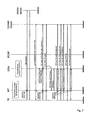
- Figure 5 shows an example, in which the media bearer is established during the session setup. Only selected messages are described while several messages serving the same purpose as the corresponding messages in figure 4 are shown in figure 5 without repetition in the text below. The following steps are taken
- the bearer is setup using an SNRPCA procedure before the parameters required for installing the uplink packet filter are available. Since the destination IP address and port to be used at the B side are not known until after receiving this information from the B-side, the uplink filter is updated later in the sequence using a PDP context modification procedure. On the B-side, the bearer is setup and the uplink packet filter is installed during this procedure, since IP address and port are known from the SIP INVITE message.
- Figure 6 shows a third signaling sequence for installation of an uplink filter. As in the previous example, only selected messages in the sequence are described while the purpose of other messages in the figure corresponds to those in figure 4 .
- the uplink packet filter on the A-side is installed together with the setup of the bearer. The following steps are taken
- the uplink filter is installed together with the setup of the bearer using a network-requested PDP context activation.
- the setup of a bearer on the A-side is delayed until the reception of the information about the destination IP address and port number from the B-side.
- the example of figure 7 shows a signaling sequence in which the filter of a preestablished bearer is modified for content upload.
- the user equipment comprises a terminal equipment TE and a mobile terminal MT and the data transmission is performed via a GSN and controlled by a PCRF.
- a packet bearer has been established between the network and the user equipment.
- the user is browsing, e.g. visiting sites on a WWW server.
- Data packets transmitted during the browsing are mapped to a bearer with default QoS.
- the user activates an upload of a file from the user equipment to an upload server, e.g. to a webblog server.
- the file upload is started with the default QoS but the data packets correspond to a new flow.
- a control entity in the network e.g. the GSN or another node in the operator's network, detects the new flow, e.g. by identifying that it is directed to a specific URL or IP address.
- a rule is activated in the control entity that determines that an uplink flow to the specific URL or IP address should be mapped to a higher QoS.
- the control entity then initiates an update of the uplink packet filter in the user equipment.
- this a done using PDP Modify procedure.
- the PDP modify could be replaced with a procedure for setting up an additional PDP context, e.g. an SNRPCA sequence.
- the upload continues preferably in parallel, using the default QoS.
- the filter in the user equipment is updated, the upload continues on a bearer with a higher QoS. This ensures priority over other traffic from the user equipment and other entities in the network.
- a control entity is shown in figure 8 . It initiates the association of a data packet with a packet bearer in a user equipment of the communication network in which the packet bearer is adapted to transmit the data packet to a further entity.
- the control entity comprises an input unit (IUC) to receive information (INF) related to the flow for the data packet.
- a processing unit (PUC) is adapted to identify the flow in an identification function (IF). For example, the identification function (IF) can evaluate the message (INF) for this purpose.
- a policy function (PF) is adapted to determine the packet bearer for association with said flow from the different packet bearers available to the user equipment.
- the control device comprises a memory with operator defined rules (OR) as basis for the determination.
- a determination function (DRI) determines a routing level identification of the further entity. The determination function (DRI) can for example also evaluate the information message (INF) or another message comprising this information.
- An output unit is adapted to instruct the user equipment to install a packet filter based on the routing level identification, the packet filter associating data packets comprising the routing level identification of the further entity with the determined packet bearer.
- the instruction is preferably performed by an instruction message (IM) to the user equipment.
- FIG. 9 shows a monitoring entity for a communication network with a user equipment.
- the monitoring entity comprises an input unit (IUM) adapted to receive an initiation message (INV) comprising a session level identification of the further entity.
- the initiation message (INV) initiates an establishment of a communication session between the user equipment and the further entity.
- the input unit (IUM) is preferably also adapted to receive a reply message (REP) to the initiation message. It is not necessary that the reply message is sent via and received by the monitoring entity if the initiation message comprises all information required to perform the proposed method such as the SIP invite message on the B-side of the embodiment in fig. 4 .
- a processing unit is adapted to monitor the messages in a monitoring function (MF) and to determine a routing level identification of the further entity from the initiation message (INV) or from the reply message (REP).
- An output unit is adapted to forward the initiation message towards the further entity using the session level identification and, if required, to forward the reply message (REP) to the user equipment.
- the monitoring entity is further adapted to forward the determined routing level identification to a control entity for instructing the user equipment to install a packet filter based on the routing level identification.
- a notification can be sent via the output unit (OUM) to the control entity.
- the monitoring entity comprises a memory (MEM) for storing an information related to the communication session. The information allows especially associating initiation message (INV) and reply message (REP) with each other and the session.
- control entity and the monitoring entity can be embodied as electronic or optical circuitry or as software executed in such circuitry.
- the input and output units of both devices may be integrated in a common I/O unit.
Landscapes
- Engineering & Computer Science (AREA)
- Computer Networks & Wireless Communication (AREA)
- Signal Processing (AREA)
- Quality & Reliability (AREA)
- Mobile Radio Communication Systems (AREA)
- Data Exchanges In Wide-Area Networks (AREA)
Claims (14)
- Verfahren zum Assoziieren eines Datenpakets (D) mit einem Paketträger (PB) in einer Benutzereinrichtung (UE1) eines Kommunikationsnetzes, wobei die Benutzereinrichtung das Datenpaket von einer Anwendungsfunktion in einem Datenfluss sendet und Mittel zum Aufbauen des Paketträgers (PB) zum Senden des Datenpakets (DP) über das Kommunikationsnetz zu einer weiteren Instanz umfasst, und wobei die Benutzereinrichtung dazu ausgelegt ist, verschiedene Paketträger aufzubauen, und das Verfahren die folgenden Schritte umfasst:Empfangen einer Anweisung durch die Benutzereinrichtung vom Kommunikationsnetz zum Installieren eines Paketfilters auf der Basis einer Leitwegebenenkennung der weiteren Instanz, wobei das Paketfilter Datenpakete des Flusses mit der Leitwegebenenkennung der weiteren Instanz mit einem bestimmten Paketträger aus den verschiedenen Paketträgern assoziiert,Bereitstellen der Leitwegebenenkennung an die Anwendungsfunktion,Aufnehmen der Leitwegebenenkennung in das Datenpaket, undSenden des Datenpakets (DP) auf dem bestimmten Paketträger (PB).
- Verfahren nach Anspruch 1, wobei die Leitwegebenenkennung der weiteren Instanz bestimmt wird und eine Steuerinstanz des Kommunikationsnetzes die bestimmte Leitwegebenenkennung von einer Überwachungsinstanz empfängt und die Benutzereinrichtung anweist, das Paketfilter zu installieren.
- Verfahren nach Anspruch 2, wobei das Verfahren die folgenden Schritte umfasst:Einleiten eines Aufbaus einer Kommunikationssitzung zwischen der Benutzereinrichtung und der weiteren Instanz durch eine Einleitungsnachricht mit einer Sitzungsebenenkennung der weiteren Instanz,Speichern einer Information in Bezug auf die Kommunikationssitzung in der Überwachungsinstanz, die dazu ausgelegt ist, Nachrichten zu überwachen, die zwischen der Benutzereinrichtung und der weiteren Instanz zum Aufbau der Sitzung gesendet werden,Weitersenden der Einleitungsnachricht zur weiteren Instanz unter Verwendung der Sitzungsebenenkennung,Warten durch die Überwachungsinstanz auf eine Antwortnachricht in Bezug auf den Aufbau der Kommunikationssitzung,Bestimmen der Leitwegebenenkennung der weiteren Instanz aus der Antwortnachricht,Weitersenden der Antwortnachricht an die Benutzereinrichtung und Abschließen des Sitzungsaufbaus.
- Verfahren nach Anspruch 2, wobei das Verfahren die folgenden Schritte umfasst:Einleiten eines Aufbaus einer Kommunikationssitzung zwischen der weiteren Instanz und der Benutzereinrichtung durch eine Einleitungsnachricht mit einer Leitwegebenenkennung der weiteren Instanz und einer Sitzungsebenenkennung der Benutzereinrichtung, Empfangen der Einleitungsnachricht in der Überwachungsinstanz und Bestimmen der Leitwegebenenkennung der weiteren Instanz aus der Einleitungsnachricht,Weitersenden der Einleitungsnachricht zur Benutzereinrichtung unter Verwendung der Sitzungsebenenkennung, und Abschließen des Sitzungsaufbaus.
- Verfahren nach einem der vorhergehenden Ansprüche, wobei anfängliche Datenpakete, die von der Benutzereinrichtung auf einem ersten Träger gesendet werden, geprüft werden, wobei der Fluss aus den geprüften Datenpaketen identifiziert wird, und wobei der zur Assoziierung mit dem Fluss bestimmte Paketträger ein zweiter Paketträger ist.
- Verfahren nach einem der vorhergehenden Ansprüche, wobei der Aufbau eines Paketträgers durch eine Anforderung von einem Knoten im Kommunikationsnetz eingeleitet wird.
- Verfahren nach einem der vorhergehenden Ansprüche, wobei die verschiedenen Paketträger sich in wenigstens einem assoziierten Element aus einer Gruppe unterscheiden, die eine Dienstgüte, einen Gebührentarif und einen Zugangspunkt, an welche das Paket gesendet wird, umfasst.
- Verfahren nach einem der vorhergehenden Ansprüche, wobei die Benutzereinrichtung eine Ausführungseinheit zum Ausführen der Anwendungsfunktion und eine Sendeeinheit zum Senden des Datenpakets auf dem bestimmten Paketträger umfasst.
- Verfahren nach deinem der vorhergehenden Ansprüche, wobei es sich bei dem Datenpaket um ein Internetprotokoll- oder IP-Datenpaket handelt.
- Verfahren nach einem der vorhergehenden Ansprüche, wobei es sich bei der Leitwegebenenkennung um wenigstens eine von einer Zieladresse und einer Zielportnummer handelt.
- Verfahren nach einem der vorhergehenden Ansprüche, wobei der Paketträger vor dem Installieren des Paketfilters aufgebaut wird, und wobei das Paketfilter in einer Modifikationsprozedur des Paketträgers installiert wird.
- Verfahren nach einem der vorhergehenden Ansprüche, wobei das Paketfilter das Datenpaket mit dem Paketträger auf der Basis wenigstens eines weiteren Parameters assoziiert.
- Benutzereinrichtung (UE1) eines Kommunikationsnetzes, wobei die Benutzereinrichtung (UE1) Mittel zum Assoziieren eines Datenpakets (D) mit einem Paketträger (PB) umfasst, wobei die Benutzereinrichtung dazu ausgelegt ist, das Datenpaket von einer Anwendungsfunktion in einem Datenfluss zu senden, und Mittel zum Aufbauen des Paketträgers (PB) zum Senden des Datenpakets (DP) über das Kommunikationsnetz zu einer weiteren Instanz umfasst, und wobei die Benutzereinrichtung dazu ausgelegt ist, verschiedene Paketträger aufzubauen, und die Benutzereinrichtung (UE1) umfasst:Mittel zum Empfangen einer Anweisung vom Kommunikationsnetz zum Installieren eines Paketfilters auf der Basis einer Leitwegebenenkennung der weiteren Instanz, wobei das Paketfilter Datenpakete des Flusses mit der Leitwegebenenkennung der weiteren Instanz mit einem bestimmten Paketträger aus den verschiedenen Paketträgern assoziiert,Mittel zum Bereitstellen der Leitwegebenenkennung an die Anwendungsfunktion,Mittel zum Aufnehmen der Leitwegebenenkennung in das Datenpaket, undMittel zum Senden des Datenpakets (DP) auf dem bestimmten Paketträger (PB).
- Benutzereinrichtung nach Anspruch 13, wobei die Benutzereinrichtung (UE1) ausgelegt ist, ein Verfahren nach einem der Ansprüche 2 bis 12 durchzuführen.
Priority Applications (2)
| Application Number | Priority Date | Filing Date | Title |
|---|---|---|---|
| PL09009986T PL2109266T3 (pl) | 2006-02-05 | 2006-02-05 | Sposób i urządzenia do instalacji filtrów pakietów w transmisji danych |
| DE602006019785T DE602006019785D1 (de) | 2006-02-05 | 2006-02-05 | Verfahren und Einrichtungen zum installieren von Paketfiltern bei einer Datenübertragung |
Applications Claiming Priority (2)
| Application Number | Priority Date | Filing Date | Title |
|---|---|---|---|
| PCT/EP2006/001004 WO2007087828A1 (en) | 2006-02-05 | 2006-02-05 | Method and devices for installing packet filters in a data transmission |
| EP06706659A EP1982475B1 (de) | 2006-02-05 | 2006-02-05 | Verfahren und einrichtungen zum installieren von paketfiltern bei einer datenübertragung |
Related Parent Applications (2)
| Application Number | Title | Priority Date | Filing Date |
|---|---|---|---|
| EP06706659A Division EP1982475B1 (de) | 2006-02-05 | 2006-02-05 | Verfahren und einrichtungen zum installieren von paketfiltern bei einer datenübertragung |
| EP06706659.7 Division | 2006-02-05 |
Publications (2)
| Publication Number | Publication Date |
|---|---|
| EP2109266A1 EP2109266A1 (de) | 2009-10-14 |
| EP2109266B1 true EP2109266B1 (de) | 2011-01-19 |
Family
ID=37151393
Family Applications (2)
| Application Number | Title | Priority Date | Filing Date |
|---|---|---|---|
| EP09009986A Active EP2109266B1 (de) | 2006-02-05 | 2006-02-05 | Verfahren und Einrichtungen zum installieren von Paketfiltern bei einer Datenübertragung |
| EP06706659A Active EP1982475B1 (de) | 2006-02-05 | 2006-02-05 | Verfahren und einrichtungen zum installieren von paketfiltern bei einer datenübertragung |
Family Applications After (1)
| Application Number | Title | Priority Date | Filing Date |
|---|---|---|---|
| EP06706659A Active EP1982475B1 (de) | 2006-02-05 | 2006-02-05 | Verfahren und einrichtungen zum installieren von paketfiltern bei einer datenübertragung |
Country Status (11)
| Country | Link |
|---|---|
| US (3) | US7907524B2 (de) |
| EP (2) | EP2109266B1 (de) |
| JP (1) | JP4960385B2 (de) |
| KR (1) | KR101098715B1 (de) |
| CN (1) | CN101336532B (de) |
| AT (2) | ATE450959T1 (de) |
| DE (2) | DE602006019785D1 (de) |
| ES (2) | ES2337720T3 (de) |
| HK (1) | HK1127937A1 (de) |
| PL (2) | PL1982475T3 (de) |
| WO (1) | WO2007087828A1 (de) |
Families Citing this family (68)
| Publication number | Priority date | Publication date | Assignee | Title |
|---|---|---|---|---|
| CN101133600B (zh) * | 2005-02-01 | 2010-11-03 | 艾利森电话股份有限公司 | 自动服务质量类别管理 |
| GB2452698B (en) | 2007-08-20 | 2010-02-24 | Ipwireless Inc | Apparatus and method for signaling in a wireless communication system |
| KR100953453B1 (ko) * | 2007-11-27 | 2010-04-20 | 한국전자통신연구원 | 이동단말에서의 상향링크 ip 패킷 필터링 제어방법 |
| EP2117266B1 (de) | 2008-05-07 | 2012-07-11 | TELEFONAKTIEBOLAGET LM ERICSSON (publ) | Verfahren, Prüfsysteme und Anordnungen zur Prüfung der Erfüllung von Anforderungsspezifikationen |
| US20090300207A1 (en) * | 2008-06-02 | 2009-12-03 | Qualcomm Incorporated | Pcc enhancements for ciphering support |
| US20090296613A1 (en) * | 2008-06-03 | 2009-12-03 | Colin Kahn | Method and apparatus for providing quality-of-service in radio access networks |
| US20100034083A1 (en) * | 2008-08-08 | 2010-02-11 | Qualcomm Incorporated | Method and apparatus for packet differentiation in a wireless communication system |
| CN101340731B (zh) * | 2008-08-22 | 2011-06-15 | 中国电信股份有限公司 | 业务的服务质量的保证方法、网络侧设备和终端 |
| US8958363B2 (en) * | 2008-10-15 | 2015-02-17 | Viasat, Inc. | Profile-based bandwidth scheduler |
| US9294902B2 (en) * | 2008-10-31 | 2016-03-22 | Telefonaktiebolaget L M Ericsson (Publ) | Policy and charging control method, servers and computer programs therefor |
| WO2010069601A1 (en) * | 2008-12-19 | 2010-06-24 | Nec Europe Ltd. | A radio network and a method for operating a radio network |
| US8270358B2 (en) * | 2009-01-12 | 2012-09-18 | Radio Ip Software Inc. | System and method for transmitting over multiple simultaneous communication networks by using roaming profiles |
| WO2010088967A1 (en) * | 2009-02-09 | 2010-08-12 | Telefonaktiebolaget L M Ericsson (Publ) | A multiple access system |
| FI20095143A0 (fi) * | 2009-02-16 | 2009-02-16 | Nethawk Oyj | Reaaliaikainen verkkodatan analysointijärjestelmä |
| WO2010098146A1 (en) * | 2009-02-27 | 2010-09-02 | Panasonic Corporation | Method for a communication node with a plurality of communication interfaces to notify dynamic path setup and associated apparatus thereof |
| DK3051872T3 (en) | 2009-04-02 | 2018-06-06 | Ericsson Telefon Ab L M | TECHNIQUES FOR MANAGING NETWORK TRAFFIC |
| CN105099933B (zh) * | 2009-04-02 | 2018-07-24 | 瑞典爱立信有限公司 | 用于处理网络通信的技术 |
| US9160566B2 (en) | 2009-04-10 | 2015-10-13 | Qualcomm Incorporated | QOS mapping for relay nodes |
| US8767545B2 (en) * | 2009-06-15 | 2014-07-01 | Qualcomm Incorporated | Radio access network control of multimedia application data rates |
| ES2362524B1 (es) * | 2009-08-27 | 2012-05-18 | Vodafone España S.A.U. | Procedimiento, sistema y dispositivo para transmitir paquetes de datos de redes multi-rat. |
| US8305979B2 (en) * | 2009-09-04 | 2012-11-06 | Clearwire Ip Holdings Llc | Managing multiple application flows over an access bearer in a quality of service policy environment |
| JP5647257B2 (ja) * | 2009-11-09 | 2014-12-24 | サムスン エレクトロニクス カンパニー リミテッド | ハンドオーバー中に単一無線映像通話連続性を支援する方法及びシステム |
| CN102075900B (zh) | 2009-11-23 | 2014-03-12 | 中兴通讯股份有限公司 | 一种实现用量监测控制的方法及系统 |
| CN102083035B (zh) * | 2009-11-30 | 2013-12-04 | 中兴通讯股份有限公司 | 一种实现用量监测控制的方法及系统 |
| US8891365B2 (en) * | 2009-12-16 | 2014-11-18 | Verizon Patent And Licensing Inc. | Dual connection admission control (CAC) at origination and destination points in LTE and EPC networks |
| US9185510B2 (en) | 2010-03-03 | 2015-11-10 | Tekelec, Inc. | Methods, systems, and computer readable media for managing the roaming preferences of mobile subscribers |
| CN101808270B (zh) * | 2010-03-10 | 2016-03-30 | 华为终端有限公司 | 一种基于Android的业务处理方法和装置 |
| US9917700B2 (en) | 2010-03-15 | 2018-03-13 | Tekelec, Inc. | Systems, methods, and computer readable media for policy enforcement correlation |
| US8484661B2 (en) * | 2010-03-19 | 2013-07-09 | At&T Mobility Ii Llc | Agnostic execution cluster for an agnostic execution environment |
| JP5408335B2 (ja) * | 2010-03-25 | 2014-02-05 | 富士通株式会社 | 移動機、パケットフィルタリング方法およびパケットフィルタリングプログラム |
| PL2996282T3 (pl) | 2010-07-29 | 2019-11-29 | Ericsson Telefon Ab L M | Obsługa transmisji sieciowej przez stały dostęp |
| US9107140B2 (en) * | 2010-08-13 | 2015-08-11 | At&T Mobility Ii Llc | Carrier-driven bearer path selection |
| WO2012045352A1 (en) * | 2010-10-06 | 2012-04-12 | Telefonaktiebolaget L M Ericsson (Publ) | Uplink traffic separation in an edge node of a communication network |
| EP2630821B1 (de) * | 2010-10-22 | 2018-03-07 | Telefonaktiebolaget LM Ericsson (publ) | Anpassung der dienstgüte bei der handhabung von netzwerkverkehr |
| CN103262505B (zh) * | 2010-10-22 | 2016-06-01 | 瑞典爱立信有限公司 | 使用网络地址转换的网络业务的区分处理 |
| WO2012052568A1 (en) * | 2010-10-22 | 2012-04-26 | Telefonaktiebolaget L M Ericsson (Publ) | Accelerated content delivery |
| US9313797B2 (en) | 2010-10-22 | 2016-04-12 | Telefonaktiebolaget Lm Ericsson (Publ) | Mobile-access information based adaptation of network address lookup for differentiated handling of data traffic |
| WO2012052067A1 (en) | 2010-10-22 | 2012-04-26 | Telefonaktiebolaget L M Ericsson (Publ) | Differentiated handling of data traffic with adaptation of network address lookup |
| JP5745078B2 (ja) * | 2010-10-27 | 2015-07-08 | インターデイジタル パテント ホールディングス インコーポレイテッド | 発展型アプリケーションインターフェースのためのスケーラブルなポリシー制御パケットインスペクションのシステムおよび方法 |
| GB2485234B (en) * | 2010-11-08 | 2015-03-25 | Sca Ipla Holdings Inc | Mobile communications device and method |
| US9112830B2 (en) * | 2011-02-23 | 2015-08-18 | Mcafee, Inc. | System and method for interlocking a host and a gateway |
| US9106769B2 (en) | 2011-08-10 | 2015-08-11 | Tekelec, Inc. | Methods, systems, and computer readable media for congestion management in a diameter signaling network |
| US10405235B2 (en) * | 2011-09-26 | 2019-09-03 | Qualcomm Incorporated | Systems and methods for traffic detection network control |
| US8792439B2 (en) * | 2011-10-05 | 2014-07-29 | Alcatel Lucent | Method and system for rate adaptive allocation of resources |
| CN103503513B (zh) * | 2012-02-06 | 2017-05-24 | 华为技术有限公司 | 用户资源请求的处理方法、装置及系统 |
| JP5260764B1 (ja) * | 2012-02-28 | 2013-08-14 | 株式会社エヌ・ティ・ティ・ドコモ | 無線通信システムおよび基地局 |
| US20130258929A1 (en) * | 2012-04-03 | 2013-10-03 | T-Mobile Usa, Inc. | Rule-Based Application Controller for Signaling Reduction |
| US9801186B2 (en) | 2012-05-10 | 2017-10-24 | Telefonaktiebolaget Lm Ericsson (Publ) | Method and apparatus to adapt the data traffic of a communication between a user equipment and a communication network |
| US9900218B2 (en) * | 2012-05-31 | 2018-02-20 | Telefonaktiebolaget L M Ericsson (Publ) | Method, user terminal, and policy and charging network entity for classifying packets |
| WO2014014829A1 (en) * | 2012-07-14 | 2014-01-23 | Tekelec, Inc. | Methods, systems, and computer readable media for dynamically controlling congestion in a radio access network |
| EP2873256B1 (de) | 2012-07-14 | 2018-09-26 | Tekelec, Inc. | Verfahren, systeme und computerlesbare medien für regelbasierte local breakout (lbo) |
| CN103581870B (zh) * | 2012-07-19 | 2019-03-12 | 中兴通讯股份有限公司 | 信息的获取、处理方法、应用功能实体和策略功能实体 |
| JP6448536B2 (ja) | 2012-07-20 | 2019-01-09 | テケレック・インコーポレイテッドTekelec, Inc. | ポリシールールをモバイルエッジに配信するための方法、システム、およびコンピュータ読取可能媒体 |
| KR20140045215A (ko) * | 2012-10-08 | 2014-04-16 | 삼성전자주식회사 | 그룹 기반 연결 설정 방법 및 장치 |
| US20150271709A1 (en) | 2012-10-12 | 2015-09-24 | Telefonaktiebolaget L M Ericsson (Publ) | Bearer Management in the RAN Based on Quality of Service |
| WO2014086398A1 (en) * | 2012-12-04 | 2014-06-12 | Telefonaktiebolaget L M Ericsson (Publ) | Method and device for an adaptive handling of data traffic |
| PL2954281T3 (pl) | 2013-02-07 | 2019-02-28 | Dyno Nobel Inc. | Systemy dostarczania materiałów wybuchowych i związane z nimi sposoby |
| WO2014191021A1 (en) * | 2013-05-28 | 2014-12-04 | Telefonaktiebolaget L M Ericsson (Publ) | Method, apparatus and computer program for updating a prioritization level of a service data flow based on traffic size per time unit of said data flow |
| WO2015010023A1 (en) | 2013-07-18 | 2015-01-22 | Convida Wireless, Llc | Billing of relayed device |
| CN104754657A (zh) * | 2013-12-30 | 2015-07-01 | 中兴通讯股份有限公司 | 策略控制方法、策略执行以及下发装置 |
| KR101936662B1 (ko) | 2014-03-05 | 2019-01-09 | 후아웨이 테크놀러지 컴퍼니 리미티드 | 데이터 패킷을 포워딩하는 액세스 노드 장치 |
| US10542452B2 (en) * | 2014-06-10 | 2020-01-21 | Apple Inc. | Enhancing quality of service for high priority services |
| CN106162758B (zh) * | 2015-03-23 | 2020-01-10 | 华为技术有限公司 | 业务处理方法、pcrf以及业务处理系统 |
| US10117127B2 (en) | 2015-07-08 | 2018-10-30 | Oracle International Corporation | Methods, systems, and computer readable media for communicating radio access network congestion status information for large numbers of users |
| KR102115218B1 (ko) | 2016-09-19 | 2020-05-26 | 에스케이텔레콤 주식회사 | 기지국장치 및 단말장치와, QoS 제어방법 |
| US10225762B2 (en) | 2017-03-28 | 2019-03-05 | Oracle International Corporation | Methods, systems, and computer readable media for message flood suppression during access node-gateway (AN-GW) unavailability and after AN-GW restoration |
| US10237418B2 (en) | 2017-04-21 | 2019-03-19 | Oracle International Corporation | Methods, systems, and computer readable media for charging based on radio congestion in mobile networks |
| US10554512B2 (en) | 2017-06-07 | 2020-02-04 | Oracle International Corporation | Methods, systems, and computer readable media for suppressing redundant packet filter installation on user equipment in a mobile network |
Family Cites Families (14)
| Publication number | Priority date | Publication date | Assignee | Title |
|---|---|---|---|---|
| IT1250515B (it) * | 1991-10-07 | 1995-04-08 | Sixtel Spa | Rete per area locale senza fili. |
| US6608832B2 (en) * | 1997-09-25 | 2003-08-19 | Telefonaktiebolaget Lm Ericsson | Common access between a mobile communications network and an external network with selectable packet-switched and circuit-switched and circuit-switched services |
| US6747986B1 (en) * | 1998-11-25 | 2004-06-08 | Telefonaktiebolaget Lm Ericsson (Publ) | Packet pipe architecture for access networks |
| GB0011058D0 (en) * | 2000-05-08 | 2000-06-28 | Nokia Networks Oy | Data bearers in a communication system |
| JP4536990B2 (ja) * | 2000-05-22 | 2010-09-01 | テレフオンアクチーボラゲット エル エム エリクソン(パブル) | アプリケーション影響ポリシー |
| US6621793B2 (en) * | 2000-05-22 | 2003-09-16 | Telefonaktiebolaget Lm Ericsson (Publ) | Application influenced policy |
| US7106718B2 (en) * | 2001-02-09 | 2006-09-12 | Telefonaktiebolaget Lm Ericsson (Publ) | Signaling quality of service class for use in multimedia communicatations |
| US7010305B2 (en) * | 2001-03-14 | 2006-03-07 | Nokia Mobile Phones, Ltd. | Method for assigning values of service attributes to transmissions, radio access networks and network elements |
| EP1250022A1 (de) * | 2001-04-09 | 2002-10-16 | Lucent Technologies Inc. | Bereitstellung einer Dienstgüte in einem Telekommunikationssystem wie zum Beispiel UMTS oder andere Systeme der dritten Generation |
| US6665280B2 (en) * | 2002-03-22 | 2003-12-16 | Nokia Corporation | Method and apparatus providing multiple temporary block flow (TBF) mapping to upper layer when operating in GSM/EDGE radio access network (GERAN) A/Gb mode |
| US6888807B2 (en) | 2002-06-10 | 2005-05-03 | Ipr Licensing, Inc. | Applying session services based on packet flows |
| BR0311681A (pt) | 2002-06-10 | 2006-11-28 | Qualcomm Inc | processamento de fluxo de pacotes em um sistema de comunicação |
| CN1726727A (zh) * | 2002-11-13 | 2006-01-25 | 诺基亚公司 | 用于执行从wlan到蜂窝网的技术间切换的方法和设备 |
| WO2005084061A1 (fr) * | 2004-01-28 | 2005-09-09 | France Telecom | Procede de gestion des ressources radio dans un reseau d’acces radio de type utran |
-
2006
- 2006-02-05 DE DE602006019785T patent/DE602006019785D1/de active Active
- 2006-02-05 CN CN2006800523703A patent/CN101336532B/zh active Active
- 2006-02-05 AT AT06706659T patent/ATE450959T1/de not_active IP Right Cessation
- 2006-02-05 WO PCT/EP2006/001004 patent/WO2007087828A1/en active Application Filing
- 2006-02-05 PL PL06706659T patent/PL1982475T3/pl unknown
- 2006-02-05 AT AT09009986T patent/ATE496464T1/de not_active IP Right Cessation
- 2006-02-05 PL PL09009986T patent/PL2109266T3/pl unknown
- 2006-02-05 JP JP2008552684A patent/JP4960385B2/ja active Active
- 2006-02-05 KR KR1020087021730A patent/KR101098715B1/ko active IP Right Grant
- 2006-02-05 US US12/278,380 patent/US7907524B2/en active Active
- 2006-02-05 ES ES06706659T patent/ES2337720T3/es active Active
- 2006-02-05 ES ES09009986T patent/ES2360110T3/es active Active
- 2006-02-05 EP EP09009986A patent/EP2109266B1/de active Active
- 2006-02-05 EP EP06706659A patent/EP1982475B1/de active Active
- 2006-02-05 DE DE602006010910T patent/DE602006010910D1/de active Active
-
2009
- 2009-06-18 HK HK09105467.4A patent/HK1127937A1/xx unknown
-
2011
- 2011-01-20 US US13/010,137 patent/US8817610B2/en active Active
-
2014
- 2014-08-06 US US14/453,353 patent/US20180254987A9/en not_active Abandoned
Also Published As
| Publication number | Publication date |
|---|---|
| PL1982475T3 (pl) | 2010-05-31 |
| ES2337720T3 (es) | 2010-04-28 |
| US7907524B2 (en) | 2011-03-15 |
| JP2009526424A (ja) | 2009-07-16 |
| ATE450959T1 (de) | 2009-12-15 |
| DE602006010910D1 (de) | 2010-01-14 |
| ATE496464T1 (de) | 2011-02-15 |
| HK1127937A1 (en) | 2009-10-09 |
| CN101336532B (zh) | 2012-01-11 |
| JP4960385B2 (ja) | 2012-06-27 |
| WO2007087828A1 (en) | 2007-08-09 |
| EP1982475A1 (de) | 2008-10-22 |
| ES2360110T3 (es) | 2011-05-31 |
| KR20080103549A (ko) | 2008-11-27 |
| US20160330121A1 (en) | 2016-11-10 |
| PL2109266T3 (pl) | 2011-09-30 |
| EP1982475B1 (de) | 2009-12-02 |
| US20180254987A9 (en) | 2018-09-06 |
| US8817610B2 (en) | 2014-08-26 |
| EP2109266A1 (de) | 2009-10-14 |
| US20090304015A1 (en) | 2009-12-10 |
| US20110122886A1 (en) | 2011-05-26 |
| KR101098715B1 (ko) | 2011-12-23 |
| CN101336532A (zh) | 2008-12-31 |
| DE602006019785D1 (de) | 2011-03-03 |
Similar Documents
| Publication | Publication Date | Title |
|---|---|---|
| EP2109266B1 (de) | Verfahren und Einrichtungen zum installieren von Paketfiltern bei einer Datenübertragung | |
| EP1972120B1 (de) | Verfahren und einrichtungen zum filtern von datenpaketen in einer übertragung | |
| EP1374494B1 (de) | Verfahren und vorrichtung zur herstellung eines protokoll-proxy für ein mobiles host-endgerät in einer multimediasitzung | |
| EP1368978B1 (de) | Zeichengabe-quality-of-service-klasse zur verwendung in multimedia-übermittlungen | |
| EP1332627B1 (de) | Verfahren und gerät für die koordinierte verrechnung von diensten in einem multimedia sitzung | |
| US20020062379A1 (en) | Method and apparatus for coordinating quality of service requirements for media flows in a multimedia session with IP bearer services | |
| US20020165966A1 (en) | Method and apparatus for coordinating end-to-end quality of service requirements for media flows in a multimedia session | |
| US20060168303A1 (en) | Method and apparatus for coordinating charging for services provided in a multimedia session | |
| US20050135389A1 (en) | Session control in a communication system | |
| WO2002037753A2 (en) | Media binding to coordinate quality of service requirements for media flows in a multimedia session with ip bearer resources | |
| EP1332632A2 (de) | Verfahren und vorrichtung zur koordination der dienstqualitätsanforderungen für medienflüsse in einer multimediasitzung mit ip-träger-betriebsmitteln | |
| EP1356631A2 (de) | Verfahren und vorrichtung zum koordinieren der ende-zu-ende-dienstqualitätsanforderungen für medienflüsse in einer multimediasitzung | |
| RU2406242C2 (ru) | Способ и устройства для установки фильтров пакетов в передаче данных | |
| MX2008009561A (en) | Method and devices for installing packet filters in a data transmission |
Legal Events
| Date | Code | Title | Description |
|---|---|---|---|
| PUAI | Public reference made under article 153(3) epc to a published international application that has entered the european phase |
Free format text: ORIGINAL CODE: 0009012 |
|
| AC | Divisional application: reference to earlier application |
Ref document number: 1982475 Country of ref document: EP Kind code of ref document: P |
|
| AK | Designated contracting states |
Kind code of ref document: A1 Designated state(s): AT BE BG CH CY CZ DE DK EE ES FI FR GB GR HU IE IS IT LI LT LU LV MC NL PL PT RO SE SI SK TR |
|
| 17P | Request for examination filed |
Effective date: 20100414 |
|
| GRAP | Despatch of communication of intention to grant a patent |
Free format text: ORIGINAL CODE: EPIDOSNIGR1 |
|
| GRAS | Grant fee paid |
Free format text: ORIGINAL CODE: EPIDOSNIGR3 |
|
| GRAA | (expected) grant |
Free format text: ORIGINAL CODE: 0009210 |
|
| AC | Divisional application: reference to earlier application |
Ref document number: 1982475 Country of ref document: EP Kind code of ref document: P |
|
| AK | Designated contracting states |
Kind code of ref document: B1 Designated state(s): AT BE BG CH CY CZ DE DK EE ES FI FR GB GR HU IE IS IT LI LT LU LV MC NL PL PT RO SE SI SK TR |
|
| REG | Reference to a national code |
Ref country code: GB Ref legal event code: FG4D |
|
| REG | Reference to a national code |
Ref country code: CH Ref legal event code: EP |
|
| REG | Reference to a national code |
Ref country code: IE Ref legal event code: FG4D |
|
| REF | Corresponds to: |
Ref document number: 602006019785 Country of ref document: DE Date of ref document: 20110303 Kind code of ref document: P |
|
| REG | Reference to a national code |
Ref country code: DE Ref legal event code: R096 Ref document number: 602006019785 Country of ref document: DE Effective date: 20110303 |
|
| REG | Reference to a national code |
Ref country code: NL Ref legal event code: T3 |
|
| REG | Reference to a national code |
Ref country code: ES Ref legal event code: FG2A Ref document number: 2360110 Country of ref document: ES Kind code of ref document: T3 Effective date: 20110531 |
|
| REG | Reference to a national code |
Ref country code: GR Ref legal event code: EP Ref document number: 20110400928 Country of ref document: GR Effective date: 20110513 |
|
| LTIE | Lt: invalidation of european patent or patent extension |
Effective date: 20110119 |
|
| PG25 | Lapsed in a contracting state [announced via postgrant information from national office to epo] |
Ref country code: LT Free format text: LAPSE BECAUSE OF FAILURE TO SUBMIT A TRANSLATION OF THE DESCRIPTION OR TO PAY THE FEE WITHIN THE PRESCRIBED TIME-LIMIT Effective date: 20110119 Ref country code: SE Free format text: LAPSE BECAUSE OF FAILURE TO SUBMIT A TRANSLATION OF THE DESCRIPTION OR TO PAY THE FEE WITHIN THE PRESCRIBED TIME-LIMIT Effective date: 20110119 Ref country code: PT Free format text: LAPSE BECAUSE OF FAILURE TO SUBMIT A TRANSLATION OF THE DESCRIPTION OR TO PAY THE FEE WITHIN THE PRESCRIBED TIME-LIMIT Effective date: 20110519 Ref country code: LV Free format text: LAPSE BECAUSE OF FAILURE TO SUBMIT A TRANSLATION OF THE DESCRIPTION OR TO PAY THE FEE WITHIN THE PRESCRIBED TIME-LIMIT Effective date: 20110119 Ref country code: IS Free format text: LAPSE BECAUSE OF FAILURE TO SUBMIT A TRANSLATION OF THE DESCRIPTION OR TO PAY THE FEE WITHIN THE PRESCRIBED TIME-LIMIT Effective date: 20110519 |
|
| PG25 | Lapsed in a contracting state [announced via postgrant information from national office to epo] |
Ref country code: CY Free format text: LAPSE BECAUSE OF FAILURE TO SUBMIT A TRANSLATION OF THE DESCRIPTION OR TO PAY THE FEE WITHIN THE PRESCRIBED TIME-LIMIT Effective date: 20110119 Ref country code: BG Free format text: LAPSE BECAUSE OF FAILURE TO SUBMIT A TRANSLATION OF THE DESCRIPTION OR TO PAY THE FEE WITHIN THE PRESCRIBED TIME-LIMIT Effective date: 20110419 Ref country code: AT Free format text: LAPSE BECAUSE OF FAILURE TO SUBMIT A TRANSLATION OF THE DESCRIPTION OR TO PAY THE FEE WITHIN THE PRESCRIBED TIME-LIMIT Effective date: 20110119 Ref country code: SI Free format text: LAPSE BECAUSE OF FAILURE TO SUBMIT A TRANSLATION OF THE DESCRIPTION OR TO PAY THE FEE WITHIN THE PRESCRIBED TIME-LIMIT Effective date: 20110119 |
|
| PG25 | Lapsed in a contracting state [announced via postgrant information from national office to epo] |
Ref country code: MC Free format text: LAPSE BECAUSE OF NON-PAYMENT OF DUE FEES Effective date: 20110228 |
|
| REG | Reference to a national code |
Ref country code: CH Ref legal event code: PL Ref country code: PL Ref legal event code: T3 |
|
| PG25 | Lapsed in a contracting state [announced via postgrant information from national office to epo] |
Ref country code: CH Free format text: LAPSE BECAUSE OF NON-PAYMENT OF DUE FEES Effective date: 20110228 Ref country code: LI Free format text: LAPSE BECAUSE OF NON-PAYMENT OF DUE FEES Effective date: 20110228 Ref country code: EE Free format text: LAPSE BECAUSE OF FAILURE TO SUBMIT A TRANSLATION OF THE DESCRIPTION OR TO PAY THE FEE WITHIN THE PRESCRIBED TIME-LIMIT Effective date: 20110119 Ref country code: DK Free format text: LAPSE BECAUSE OF FAILURE TO SUBMIT A TRANSLATION OF THE DESCRIPTION OR TO PAY THE FEE WITHIN THE PRESCRIBED TIME-LIMIT Effective date: 20110119 |
|
| REG | Reference to a national code |
Ref country code: IE Ref legal event code: MM4A |
|
| PLBE | No opposition filed within time limit |
Free format text: ORIGINAL CODE: 0009261 |
|
| STAA | Information on the status of an ep patent application or granted ep patent |
Free format text: STATUS: NO OPPOSITION FILED WITHIN TIME LIMIT |
|
| PG25 | Lapsed in a contracting state [announced via postgrant information from national office to epo] |
Ref country code: CZ Free format text: LAPSE BECAUSE OF FAILURE TO SUBMIT A TRANSLATION OF THE DESCRIPTION OR TO PAY THE FEE WITHIN THE PRESCRIBED TIME-LIMIT Effective date: 20110119 Ref country code: RO Free format text: LAPSE BECAUSE OF FAILURE TO SUBMIT A TRANSLATION OF THE DESCRIPTION OR TO PAY THE FEE WITHIN THE PRESCRIBED TIME-LIMIT Effective date: 20110119 Ref country code: SK Free format text: LAPSE BECAUSE OF FAILURE TO SUBMIT A TRANSLATION OF THE DESCRIPTION OR TO PAY THE FEE WITHIN THE PRESCRIBED TIME-LIMIT Effective date: 20110119 |
|
| 26N | No opposition filed |
Effective date: 20111020 |
|
| PG25 | Lapsed in a contracting state [announced via postgrant information from national office to epo] |
Ref country code: IE Free format text: LAPSE BECAUSE OF NON-PAYMENT OF DUE FEES Effective date: 20110205 |
|
| REG | Reference to a national code |
Ref country code: DE Ref legal event code: R097 Ref document number: 602006019785 Country of ref document: DE Effective date: 20111020 |
|
| REG | Reference to a national code |
Ref country code: AT Ref legal event code: MK05 Ref document number: 496464 Country of ref document: AT Kind code of ref document: T Effective date: 20110119 |
|
| PG25 | Lapsed in a contracting state [announced via postgrant information from national office to epo] |
Ref country code: PL Free format text: LAPSE BECAUSE OF NON-PAYMENT OF DUE FEES Effective date: 20110205 |
|
| REG | Reference to a national code |
Ref country code: PL Ref legal event code: LAPE |
|
| PG25 | Lapsed in a contracting state [announced via postgrant information from national office to epo] |
Ref country code: LU Free format text: LAPSE BECAUSE OF NON-PAYMENT OF DUE FEES Effective date: 20110205 |
|
| PG25 | Lapsed in a contracting state [announced via postgrant information from national office to epo] |
Ref country code: TR Free format text: LAPSE BECAUSE OF FAILURE TO SUBMIT A TRANSLATION OF THE DESCRIPTION OR TO PAY THE FEE WITHIN THE PRESCRIBED TIME-LIMIT Effective date: 20110119 |
|
| PG25 | Lapsed in a contracting state [announced via postgrant information from national office to epo] |
Ref country code: HU Free format text: LAPSE BECAUSE OF FAILURE TO SUBMIT A TRANSLATION OF THE DESCRIPTION OR TO PAY THE FEE WITHIN THE PRESCRIBED TIME-LIMIT Effective date: 20110119 |
|
| REG | Reference to a national code |
Ref country code: FR Ref legal event code: PLFP Year of fee payment: 11 |
|
| REG | Reference to a national code |
Ref country code: FR Ref legal event code: PLFP Year of fee payment: 12 |
|
| REG | Reference to a national code |
Ref country code: FR Ref legal event code: PLFP Year of fee payment: 13 |
|
| REG | Reference to a national code |
Ref country code: FR Ref legal event code: PLFP Year of fee payment: 18 |
|
| P01 | Opt-out of the competence of the unified patent court (upc) registered |
Effective date: 20230523 |
|
| PGFP | Annual fee paid to national office [announced via postgrant information from national office to epo] |
Ref country code: GR Payment date: 20240227 Year of fee payment: 19 |
|
| PGFP | Annual fee paid to national office [announced via postgrant information from national office to epo] |
Ref country code: ES Payment date: 20240301 Year of fee payment: 19 Ref country code: NL Payment date: 20240226 Year of fee payment: 19 |
|
| PGFP | Annual fee paid to national office [announced via postgrant information from national office to epo] |
Ref country code: FI Payment date: 20240226 Year of fee payment: 19 Ref country code: DE Payment date: 20240228 Year of fee payment: 19 Ref country code: GB Payment date: 20240227 Year of fee payment: 19 |
|
| PGFP | Annual fee paid to national office [announced via postgrant information from national office to epo] |
Ref country code: IT Payment date: 20240222 Year of fee payment: 19 Ref country code: FR Payment date: 20240226 Year of fee payment: 19 Ref country code: BE Payment date: 20240227 Year of fee payment: 19 |