EP2109206B1 - Generator with a stator comprising cooling ducts and method for cooling a laminated stator of a generator - Google Patents
Generator with a stator comprising cooling ducts and method for cooling a laminated stator of a generator Download PDFInfo
- Publication number
- EP2109206B1 EP2109206B1 EP08007144.2A EP08007144A EP2109206B1 EP 2109206 B1 EP2109206 B1 EP 2109206B1 EP 08007144 A EP08007144 A EP 08007144A EP 2109206 B1 EP2109206 B1 EP 2109206B1
- Authority
- EP
- European Patent Office
- Prior art keywords
- cooling
- generator
- stator
- duct
- ducts
- Prior art date
- Legal status (The legal status is an assumption and is not a legal conclusion. Google has not performed a legal analysis and makes no representation as to the accuracy of the status listed.)
- Expired - Fee Related
Links
Images

Classifications
-
- H—ELECTRICITY
- H02—GENERATION; CONVERSION OR DISTRIBUTION OF ELECTRIC POWER
- H02K—DYNAMO-ELECTRIC MACHINES
- H02K1/00—Details of the magnetic circuit
- H02K1/06—Details of the magnetic circuit characterised by the shape, form or construction
- H02K1/12—Stationary parts of the magnetic circuit
- H02K1/20—Stationary parts of the magnetic circuit with channels or ducts for flow of cooling medium
-
- H—ELECTRICITY
- H02—GENERATION; CONVERSION OR DISTRIBUTION OF ELECTRIC POWER
- H02K—DYNAMO-ELECTRIC MACHINES
- H02K9/00—Arrangements for cooling or ventilating
- H02K9/19—Arrangements for cooling or ventilating for machines with closed casing and closed-circuit cooling using a liquid cooling medium, e.g. oil
-
- H—ELECTRICITY
- H02—GENERATION; CONVERSION OR DISTRIBUTION OF ELECTRIC POWER
- H02K—DYNAMO-ELECTRIC MACHINES
- H02K7/00—Arrangements for handling mechanical energy structurally associated with dynamo-electric machines, e.g. structural association with mechanical driving motors or auxiliary dynamo-electric machines
- H02K7/18—Structural association of electric generators with mechanical driving motors, e.g. with turbines
- H02K7/1807—Rotary generators
- H02K7/1823—Rotary generators structurally associated with turbines or similar engines
- H02K7/183—Rotary generators structurally associated with turbines or similar engines wherein the turbine is a wind turbine
- H02K7/1838—Generators mounted in a nacelle or similar structure of a horizontal axis wind turbine
-
- Y—GENERAL TAGGING OF NEW TECHNOLOGICAL DEVELOPMENTS; GENERAL TAGGING OF CROSS-SECTIONAL TECHNOLOGIES SPANNING OVER SEVERAL SECTIONS OF THE IPC; TECHNICAL SUBJECTS COVERED BY FORMER USPC CROSS-REFERENCE ART COLLECTIONS [XRACs] AND DIGESTS
- Y02—TECHNOLOGIES OR APPLICATIONS FOR MITIGATION OR ADAPTATION AGAINST CLIMATE CHANGE
- Y02E—REDUCTION OF GREENHOUSE GAS [GHG] EMISSIONS, RELATED TO ENERGY GENERATION, TRANSMISSION OR DISTRIBUTION
- Y02E10/00—Energy generation through renewable energy sources
- Y02E10/70—Wind energy
- Y02E10/72—Wind turbines with rotation axis in wind direction
Abstract
Description
- The present invention relates to a generator with a stator made of laminate plates and comprising cooling ducts. It further relates to a method for cooling a laminated stator of a generator.
- High power generators, especially of modern wind turbines, produce large amounts of thermal energy, which must be dissipated to avoid damage to, for example, the electrical insulation of the generator. The cooling systems of wind turbine generators are typically based on air cooling or closed circuit water cooling.
- In
US 2007/0024132 A1 a wind turbine generator comprising a stator with heat pipes integrated in the stator yoke is described. The heat pipes run in axial direction. The heat is absorbed or transferred from the components into an evaporator section of the heat pipe, particularly a vaporisable liquid in the heat pipe. The heat pipe is arranged with respect to a stator core such that the evaporator section extends into and is received within a bore which is configured to receive a corresponding heat pipe. - A system of axially oriented cooling slits for air cooling in the stator of a wind turbine is presented in
EP 1 586 769 A2 . - In
EP 0 627 804 A2 a dynamoelectric machine comprising a plurality of stacked laminations without end plates forming a stator core with air ducts passing through the entire length of the stator is disclosed. The stacked laminations have a central bore for passage of a rotor there through and a plurality of winding slots extending radially outward from the bore. A plurality of cooling air passages extend axially through the stacked laminations generally parallel to the central bore. Each of the air passages are positioned adjacent to the terminating end of a corresponding one of the winding slots. - In
US 4 691 131 a stator of an AC motor with axially oriented passages for cooling liquid is described. The laminated core is impregnated with a resin to fill gaps between adjacent laminations and coat inner surfaces of the cooling liquid passages so that cooling liquid will flow through the cooling liquid passages without leakage therefrom. -
DE 297 07 181 U1 describes a generator with stator laminate plates which are provided with windows. The windows are aligned such relative to each other that they form cooling ducts for a cooling liquid to flow there through. The cooling liquid may, in particular, be transformer oil. -
WO 01/21956 A1 -
DE 198 24 202 C1 describes an electric motor which is cooled by a liquid. The motor is located in a housing which is provided with ducts for the cooling liquid. The upper side of the housing is further provided with openings through which the cooling fluid can be sprayed onto the motor. A liquid reservoir is present at the bottom of the housing from which the liquid can be led away in order to remove the heat introduced into the liquid by the motor. - It is an objective of the present invention to provide an advantageous generator comprising a plurality of stator laminate plates. It is a second objective of the present invention to provide an advantageous wind turbine. It is another objective of the present invention to provide an advantageous method for cooling a laminated stator of a generator.
- The first objective is solved by a generator as claimed in claim 1. The second objective is solved by a wind turbine as claimed in
claim 10. The last objective is solved by a method for cooling a laminated stator of a generator as claimed inclaim 11. The depending claims define further developments of the invention. The features are advantageous separate and in combination with each other. - The inventive generator comprises two end plates and a plurality of stator laminate plates arranged between the two end plates. Each laminate plate and each end plate comprise a number of cooling holes which are located such that the cooling holes of the laminate plates and the cooling holes of the end plates are aligned with each other to form a number of cooling ducts by the stator material itself. The end plates may advantageously be used to compress the stator laminates to form the laminated stator core and at the same time provide support for the end loops of the stator coils. The holes may be punched in the stator laminates.
- Forming the cooling ducts by the stator itself avoids the need for an impregnation or the need for an additional duct. A used cooling fluid, for example a liquid, comes directly into contact with the stator material and therefore effectively cools the stator material.
- The inventive generator comprises a rotation axis and the cooling ducts may run parallel to the rotation axis. Moreover, the cooling ducts may extend throughout the entire length of the stator.
- The cooling holes in one of the end plates can be fitted with nipples to which a tubing, for example a rubber or plate tubing, can be attached. Furthermore, the cooling holes in one of the end plates can be fitted with orifices. For example, the holes in one of the end plates may be fitted with nipples to which rubber or plastic tubing can be attached and the holes in the opposite end plate may be fitted with orifices that act as simple throttles for a liquid flow. The nipples at the first stator end plate facilitate piping. The orifices at the other end of the stator ensure even flow through all cooling ducts by ensuring that the pressure loss is generally concentrated at the end of the cooling ducts.
- The inventive generator advantageously comprises a reservoir for a cooling fluid, for example a cooling liquid, which is in flow connection with the cooling ducts. Moreover, the generator comprises a housing with a bottom, and the reservoir for the cooling fluid, for example a cooling liquid, is located at the bottom of the housing and connected to the cooling ducts via the tubing. When the cooling fluid emerges from the ducts at the second end plate it is simply be allowed to fall into the reservoir at the bottom of the generator housing.
- The inventive generator can comprise a cooling liquid that is stable at high temperatures and has electrically insulating properties. The cooling liquid may, for example, be transformer oil.
- The inventive generator may further comprise a pump for pumping the cooling fluid through a circuit comprising the cooling ducts. The generator comprises an open cooling fluid circuit. When the cooling fluid emerges from the ducts at the second end plate it is simply be allowed to fall into the reservoir at the bottom of the generator housing. Furthermore, the circuit may especially comprise a heat exchanger.
- The inventive wind turbine comprises a generator as previously described. The inventive wind turbine has the same advantages as the inventive generator.
- In the inventive method for cooling a laminated stator of a generator a cooling liquid is guided via a tubing from a cooling liquid reservoir into at least one partly open cooling duct in the laminated stator. Advantageously, the cooling liquid is pumped into the cooling duct.
- The cooling liquid is let to return to the reservoir under the influence of gravity alone. Preferably, a cooling liquid can be used which is stable at high temperatures and has electrically insulating properties. For example, transformer oil may be used as cooling liquid. A cooling duct is used which is formed by holes in the stator material itself.
- The present invention provides a liquid-based cooling system for the stator of a generator, for example of wind turbine, where the walls of the cooling ducts are formed by the stator itself. This allows for direct thermal contact between the stator and the cooling fluid.
- In addition, the cooling ducts are simple to manufacture, using well-known punching techniques. No cooling tubes need to be welded or braced onto the stator.
- The system is partly open. Leakage may occur between adjacent stator laminates, but since the fluid is electrically insulating this does no harm and the cooling fluid returns to the reservoir under the influence of gravity alone. No conduits carrying the cooling fluid from the stator and back to the reservoir are necessary. This saves considerable costs in tubing and time for assembly.
- Further features, properties and advantages of the present invention will become clear from the following description of an embodiment in conjunction with the accompanying drawings.
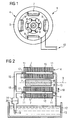
- Fig. 1
- schematically shows a generator.
- Fig. 2
- schematically shows an inventive generator in a sectional view.
- Fig. 3
- schematically shows a stator laminate plate in a frontal view.
- An embodiment of the present invention will now be described with reference to
figures 1 to 3 .Figure 1 schematically shows a generator in a simplified view. The generator 1 comprises astator 4 and a rotor 2. Thestator 4 comprises a stator housing 5,stator laminate plates 7 and stator inductor coils 9. Thestator laminate plates 7 and the stator inductor coils 9 are located inside the stator housing 5. The stator inductor coils 9 are coiled up around the stator laminate plates. - The rotor 2 is located inside the stator housing 5 and is able to rotate about a
rotation axis 3. The rotor 2 comprises a number of rotor inductor coils 8 for induction of an alternating magnetic field. The rotor inductor coils 8 are provided with DC current by means of a contact ring and acontact brush 6, for example. - The stator inductor coils 9 are connected to an
electrical grid 10 for providing alternating current. The generator 1 converts mechanical energy, which causes a rotation of the rotor 2, to electrical energy by means of electromagnetic induction. In addition, the rotor 2 may also be connected to a grid, for example, in case of a doubly fed generator. - Note, that the generator in
figure 1 is simplified and that a real generator comprises a larger number of poles. -
Figure 2 schematically shows an inventive generator in a sectional view along therotation axis 3. The figure shows a rotor 2, astator 4, and a cooling liquid circuit. - The
stator 4 comprises a number ofstator laminate plates 7 and twoend plates 11. Thestator laminate plates 7 are arranged between the twoend plates 11. Theend plates 11 are used to compress thestator laminates 7 to form the laminated stator core and at the same time provide support for the end loops of the stator coils 9. Eachstator laminate plate 7 and eachend plate 11 comprises a number ofholes 21 which are located such that theholes 21 of thelaminate plates 7 and theholes 21 of theend plates 11 are aligned with each other when thestator 4 is assembled to form a number ofcooling ducts 15. The coolingducts 15 are formed by the stator material itself, i.e. they are not covered by a resin or the like. - Each cooling
duct 15 comprises aduct inlet 17 which is located in one of theend plates 11 and aduct outlet 18 which is located in theopposite end plate 11. Theduct inlet 17 is connected to areservoir 12 by means of atubing 16. Thereservoir 12 is filled with transformer oil as coolingliquid 13. Between thereservoir 12 and the duct inlet 17 apump 14 and aheat exchanger 20 are located. Theheat exchanger 20 can also be placed at another position. The coolingliquid 13 can be pumped by means of thepump 14 through thetubing 16 into theducts 15. The direction of the cooling liquid flow is indicated byarrows 19. The coolingliquid 13 which has passed theducts 15 of thestator 4 is let to return to thereservoir 12 under the influence of gravity alone. - The duct inlets 17 may be fitted with nipples which facilitate piping. Rubber or
plastic tubing 16 can be attached to the nipples. Moreover, theduct outlets 18 can be fitted with orifices that act as simple throttles for the liquid flow. The orifices at theduct outlets 18 ensure even flow through all cooling ducts by ensuring that the pressure loss is generally concentrated at the end of thecooling ducts 15. When the coolingfluid 13 emerges from theducts 15 at theduct outlet 18 it is simply be allowed to fall into thereservoir 12 at the bottom of the generator housing. - Generally, the cooling fluid can be transformer oil as in the present embodiment or a similar liquid that is stable at high temperatures and has good electrically insulating properties.
- In the partly open system, which is shown in
figure 2 , leakage may occur betweenadjacent stator laminates 7, but since the fluid 13 is electrically insulating this does no harm, and the coolingfluid 13 returns to thereservoir 12 under the influence of gravity alone. No conduits carrying the coolingfluid 13 from thestator 4 and back to thereservoir 12 are necessary. This saves considerable costs in tubing and time of assembly. - In
figure 2 thecooling ducts 15 are orientated parallel to therotation axis 3. Of course, theducts 15 can be orientated in another way. Moreover, the coolingducts 15 extend throughout the entire length of thestator 4. -
Figure 3 schematically shows astator laminate plate 7 for a real generator with a large number of poles in a frontal view. Thestator laminate plate 7 comprises a plurality ofholes 21 which are located near the outer diameter of theplate 7. Furthermore, theholes 21 are uniformly distributed along the perimeter of theplate 7. The coolingducts 15 which are formed by theholes 21 are simple to manufacture, using well-known punching techniques. No cooling tubes need to be welded or braced onto the stator. - The inventive generator as well as the inventive method, wherein the
stator cooling ducts 15 are formed by thestator 4 itself, allow for direct thermal contact between thestator 4 and the coolingfluid 13 and provides an effective cooling.
Claims (14)
- A generator (1) comprising two end plates (11) and a plurality of stator laminate plates (7) arranged between the two end plates (11), each laminate plate (7) and each end plate (11) comprising a number of cooling holes (21) which are located such that the cooling holes (21) of the laminate plates (7) and the cooling holes of the end plates (11) are aligned with each other to form a number of cooling ducts (15) by the stator material itself, each cooling duct comprising a duct inlet (17) and a duct outlet (18),
wherein the generator (1) comprises a housing (5) with a bottom and a reservoir (12) for a cooling fluid (13) which is located at the bottom of the housing (5) and connected to the cooling ducts (15) via a tubing,
wherein the tubing connects the reservoir only to the duct inlet (17) and wherein the duct outlet (18) allows the cooling fluid to fall into the reservoir (12) at the bottom of the generator housing thereby forming an open cooling circuit. - The generator (1) as claimed in claim 1,
wherein the generator (1) comprises a rotation axis (3) and the cooling ducts (15) run parallel to the rotation axis. - The generator (1) as claimed in claim 1 or 2,
wherein the cooling ducts (15) extend throughout the entire length of the stator (4). - The generator (1) as claimed in any of the claims 1 to 3,
wherein the cooling holes in one of the end plates (11) are fitted with nipples to which a tubing can be attached. - The generator (1) as claimed in any of the claims 1 to 4,
wherein the cooling holes in one of the end plates (11) are fitted with orifices. - The generator (1) as claimed in any of the claims 1 to 5, wherein the generator (1) comprises a cooling liquid (13) that is stable at high temperatures and has electrically insulating properties.
- The generator (1) as claimed in claim 7,
wherein the cooling liquid (13) is transformer oil. - The generator (1) as claimed in any of the claims 1 to 7,
wherein the generator (1) comprises a pump (14) for pumping the cooling fluid (13) through a circuit comprising the cooling ducts (15). - The generator (1) as claimed in claim 8,
wherein the circuit comprises a heat exchanger (20). - A wind turbine comprising a generator (1) as claimed in any of the claims 1 to 9.
- A method for cooling a laminated stator (4) of a generator (1), comprising two end plates (11) and a plurality of stator laminate plates (7) arranged between the two end plates (11), each laminate plate (7) and each end plate (11) comprising a number of cooling holes (21) which are located such that the cooling holes (21) of the laminate plates (7) and the cooling holes of the end plates (11) are aligned with each other to form a number of cooling ducts (15) by the stator material itself, each cooling duct comprising a duct inlet (17) and a duct outlet (18),
wherein the generator (1) comprises a housing (5) with a bottom and a reservoir (12) for a cooling fluid (13) which is located at the bottom of the housing (5) and connected to the cooling ducts (15) via a tubing,
wherein the tubing connects the reservoir only to the duct inlet (17) and wherein the duct outlet (18) allows the cooling fluid to fall into the reservoir (12) at the bottom of the generator housing thereby forming an open cooling circuit
characterised in that
a cooling liquid (13) is guided via the tubing from the cooling liquid reservoir (12) into the cooling duct (15) in the laminated stator (4), and the cooling liquid from the duct outlet falls into the reservoir (12) at the bottom of the generator housing. - The method as claimed in claim 11,
characterised in that
the cooling liquid (13) is pumped into the cooling duct (15). - The method as claimed in any of the claims 11 to 12,
characterised in that
a cooling liquid (13) is used which is stable at high temperatures and has electrically insulating properties. - The method as claimed in claim 13,
characterised in that
transformer oil is used as cooling liquid (13).
Priority Applications (5)
| Application Number | Priority Date | Filing Date | Title |
|---|---|---|---|
| ES08007144T ES2415661T3 (en) | 2008-04-10 | 2008-04-10 | Generator with a stator comprising cooling channels and method for cooling a laminated stator of a generator |
| EP08007144.2A EP2109206B1 (en) | 2008-04-10 | 2008-04-10 | Generator with a stator comprising cooling ducts and method for cooling a laminated stator of a generator |
| DK08007144.2T DK2109206T3 (en) | 2008-04-10 | 2008-04-10 | Generator with a stator comprising cooling ducts as well as method for cooling a laminated stator by a generator |
| US12/383,980 US8519577B2 (en) | 2008-04-10 | 2009-03-31 | Generator with a stator comprising cooling ducts, and method for cooling a laminated stator of a generator |
| CN200910134329.6A CN101557131B (en) | 2008-04-10 | 2009-04-10 | Generator with stator comprising cooling ducts and method for cooling laminated stator of generator |
Applications Claiming Priority (1)
| Application Number | Priority Date | Filing Date | Title |
|---|---|---|---|
| EP08007144.2A EP2109206B1 (en) | 2008-04-10 | 2008-04-10 | Generator with a stator comprising cooling ducts and method for cooling a laminated stator of a generator |
Publications (2)
| Publication Number | Publication Date |
|---|---|
| EP2109206A1 EP2109206A1 (en) | 2009-10-14 |
| EP2109206B1 true EP2109206B1 (en) | 2013-05-29 |
Family
ID=39735462
Family Applications (1)
| Application Number | Title | Priority Date | Filing Date |
|---|---|---|---|
| EP08007144.2A Expired - Fee Related EP2109206B1 (en) | 2008-04-10 | 2008-04-10 | Generator with a stator comprising cooling ducts and method for cooling a laminated stator of a generator |
Country Status (5)
| Country | Link |
|---|---|
| US (1) | US8519577B2 (en) |
| EP (1) | EP2109206B1 (en) |
| CN (1) | CN101557131B (en) |
| DK (1) | DK2109206T3 (en) |
| ES (1) | ES2415661T3 (en) |
Families Citing this family (31)
| Publication number | Priority date | Publication date | Assignee | Title |
|---|---|---|---|---|
| DE102008001622A1 (en) * | 2008-05-07 | 2009-11-12 | Robert Bosch Gmbh | Electric machine with spray and sump cooling |
| US8519581B2 (en) | 2010-06-08 | 2013-08-27 | Remy Technologies, Llc | Electric machine cooling system and method |
| DK2442060T3 (en) * | 2010-10-13 | 2014-01-06 | Siemens Ag | Generator, especially for a wind turbine |
| US8546983B2 (en) | 2010-10-14 | 2013-10-01 | Remy Technologies, Llc | Split drain system and method for an electric machine module |
| EP2451058A1 (en) * | 2010-11-04 | 2012-05-09 | Siemens Aktiengesellschaft | Welded manifold for a stator core segment |
| EP2451047A1 (en) * | 2010-11-04 | 2012-05-09 | Siemens Aktiengesellschaft | Water cooled electric machine |
| EP2521246A1 (en) * | 2011-05-03 | 2012-11-07 | Siemens Aktiengesellschaft | Stator arrangement |
| DE102011081539A1 (en) * | 2011-08-25 | 2013-02-28 | Siemens Aktiengesellschaft | Electric machine with damper screen |
| EP2565445B1 (en) | 2011-09-02 | 2014-02-26 | Siemens Aktiengesellschaft | Transformer chamber for a wind turbine, wind turbine structure component, wind turbine, and method for assembling a wind turbine |
| US9467010B2 (en) | 2011-11-17 | 2016-10-11 | Remy Technologies, L.L.C. | Method of winding a stator core with a continuous conductor having a rectangular cross-section and a stator core |
| US8745847B2 (en) | 2011-11-17 | 2014-06-10 | Remy Technologies, L.L.C. | Method of P-forming a continuous conductor having a rectangular cross section and a stator including a stator winding formed from a P-formed conductor having a rectangular cross-section |
| US8789259B2 (en) | 2011-11-17 | 2014-07-29 | Remy Technologies, L.L.C. | Method of winding a stator core with a continuous conductor having a rectangular cross-section and a stator core |
| EP2645534B1 (en) * | 2012-03-26 | 2018-01-31 | Siemens Aktiengesellschaft | Magnet component with a thermal insulation structure, rotor assembly with such a magnet component, electromechanical transducer and wind turbine |
| DK201270179A (en) * | 2012-04-11 | 2013-10-11 | Envision Energy Denmark Aps | Wind turbine with improved cooling |
| CN103001397A (en) * | 2012-10-31 | 2013-03-27 | 苏州萃智新技术开发有限公司 | Water cooling device for motor |
| US9293965B2 (en) * | 2013-08-05 | 2016-03-22 | GM Global Technology Operations LLC | Apparatus, system, and method for cooling an electric motor |
| EP3079239B1 (en) * | 2015-04-09 | 2020-06-17 | GE Energy Power Conversion Technology Ltd | Electrical machine and method |
| US9394618B1 (en) | 2015-07-20 | 2016-07-19 | Siemens Energy, Inc. | System and method for cleaning stator cooling coils |
| CN105790509A (en) * | 2016-04-07 | 2016-07-20 | 重庆大学 | Micro-flow-path-channel-based auxiliary cooling system for operation power apparatus |
| CN106411084A (en) * | 2016-10-09 | 2017-02-15 | 中国人民解放军海军工程大学 | High power mixed excitation motor with novel water-cooling structure |
| WO2018105143A1 (en) * | 2016-12-05 | 2018-06-14 | 三菱電機株式会社 | Dynamo-electric machine |
| US11128201B2 (en) | 2017-09-06 | 2021-09-21 | Ge Aviation Systems Llc | Method and assembly of a stator sleeve |
| DE102017221803A1 (en) * | 2017-12-04 | 2019-06-06 | Mahle International Gmbh | Electric machine, in particular for a vehicle |
| DE102019208293A1 (en) * | 2019-06-06 | 2020-12-10 | Zf Friedrichshafen Ag | Shaft for an electric machine |
| EP3793063A1 (en) | 2019-09-11 | 2021-03-17 | Dana Belgium N.V. | Stack of laminations for a stator having cooling channels |
| DE102020111444A1 (en) | 2020-04-27 | 2021-10-28 | Technische Universität Dresden, Körperschaft des öffentlichen Rechts | Generator system and method for operating a generator system |
| US11961660B2 (en) | 2020-08-31 | 2024-04-16 | General Electric Company | Systems and methods for assembling a magnetic-core assembly |
| US11916459B2 (en) | 2020-12-30 | 2024-02-27 | Dana Heavy Vehicle Systems Group, Llc | Systems and method for an electric motor with spray ring |
| US11770041B2 (en) | 2020-12-30 | 2023-09-26 | Dana Heavy Vehicle Systems Group, Llc | Systems and method for an electric motor with molded coolant jacket and spray ring |
| US20230093220A1 (en) * | 2021-09-21 | 2023-03-23 | Dana Automotive Systems Group, Llc | Electric motor with water jacket and oil-cooled stator and method for operation of the electric motor |
| EP4170875A1 (en) | 2021-10-21 | 2023-04-26 | voestalpine Stahl GmbH | Method for manufacturing at least one fluid channel in a laminated core and laminated core made with same |
Family Cites Families (17)
| Publication number | Priority date | Publication date | Assignee | Title |
|---|---|---|---|---|
| US3574325A (en) * | 1969-02-19 | 1971-04-13 | Gen Motors Corp | Braking system for electric motors |
| US3743867A (en) * | 1971-12-20 | 1973-07-03 | Massachusetts Inst Technology | High voltage oil insulated and cooled armature windings |
| JPS61121728A (en) | 1984-11-14 | 1986-06-09 | Fanuc Ltd | Liquid cooled motor |
| US5365132A (en) | 1993-05-27 | 1994-11-15 | General Electric Company | Lamination for a dynamoelectric machine with improved cooling capacity |
| DE29707181U1 (en) * | 1997-04-12 | 1997-06-12 | Struckmeier Gmbh Antriebstechn | Laminated core with fluid-flowed cooling windows for electrical machines |
| JPH11318055A (en) * | 1998-05-07 | 1999-11-16 | Toyota Motor Corp | Cooling controller and cooling control method of rotary electric machine |
| JP4052492B2 (en) * | 1998-05-15 | 2008-02-27 | ヤマハマリン株式会社 | Outboard motor |
| DE19824202C1 (en) * | 1998-05-29 | 1999-09-30 | Siemens Ag | Liquid-cooled electric internal rotor machine e.g. for traction motor of rail-vehicles |
| SE9901919L (en) * | 1999-05-27 | 2000-11-28 | Abb Ab | Cooling of rotating electric machines for high voltage |
| NL1013129C2 (en) * | 1999-09-24 | 2001-03-27 | Lagerwey Windturbine B V | Windmill. |
| DE10027246C1 (en) * | 2000-05-31 | 2001-10-31 | Mannesmann Sachs Ag | Electrical machine has axial cooling channels in first set of stator laminations coupled together via deflection elements provided via second set of stator laminations |
| US6954010B2 (en) * | 2002-05-06 | 2005-10-11 | Aerovironment, Inc. | Lamination cooling system |
| ES2233146B1 (en) * | 2002-11-21 | 2006-06-01 | Manuel Torres Martinez | MULTIPOLAR ALTERNATOR FOR AEROGENERATORS. |
| US20050067905A1 (en) * | 2003-09-30 | 2005-03-31 | Mark Maney | Stator cooling method and apparatus |
| DE102004018758A1 (en) | 2004-04-16 | 2005-11-03 | Klinger, Friedrich, Prof. Dr.-Ing. | Tower head of a wind turbine |
| JP4586542B2 (en) * | 2005-01-17 | 2010-11-24 | トヨタ自動車株式会社 | Rotating electric machine |
| US7443066B2 (en) * | 2005-07-29 | 2008-10-28 | General Electric Company | Methods and apparatus for cooling wind turbine generators |
-
2008
- 2008-04-10 DK DK08007144.2T patent/DK2109206T3/en active
- 2008-04-10 ES ES08007144T patent/ES2415661T3/en active Active
- 2008-04-10 EP EP08007144.2A patent/EP2109206B1/en not_active Expired - Fee Related
-
2009
- 2009-03-31 US US12/383,980 patent/US8519577B2/en not_active Expired - Fee Related
- 2009-04-10 CN CN200910134329.6A patent/CN101557131B/en not_active Expired - Fee Related
Also Published As
| Publication number | Publication date |
|---|---|
| CN101557131A (en) | 2009-10-14 |
| DK2109206T3 (en) | 2013-06-17 |
| ES2415661T3 (en) | 2013-07-26 |
| CN101557131B (en) | 2014-02-05 |
| US20090256433A1 (en) | 2009-10-15 |
| US8519577B2 (en) | 2013-08-27 |
| EP2109206A1 (en) | 2009-10-14 |
Similar Documents
| Publication | Publication Date | Title |
|---|---|---|
| EP2109206B1 (en) | Generator with a stator comprising cooling ducts and method for cooling a laminated stator of a generator | |
| EP2667486B1 (en) | Electric machine rotor cooling method | |
| US20150188391A1 (en) | Apparatus for cooling an electromagnetic machine | |
| KR101858441B1 (en) | Modes of cooling hybrid electric machines | |
| EP2806537B1 (en) | Rotary electric generator stator, rotary electric generator comprising said stator, and wind turbine incorporating said rotary electric generator | |
| CN202840768U (en) | Motor and gap tube for motor | |
| EP2182570A1 (en) | Arrangement for cooling of an electrical machine | |
| US9148040B2 (en) | Electromagnetic component for a stator segment of an electrical machine | |
| CN103208883A (en) | Wind turbine with improved cooling device | |
| US20090083966A1 (en) | High efficiency salient pole machine and method of forming the same | |
| US11677289B2 (en) | Electric power system for hypersonic speed operation | |
| KR20110103955A (en) | Electrical machine and method for the manufacturing of stator sections therefor | |
| KR20130066517A (en) | Electric machine module cooling system and method | |
| US8872399B2 (en) | Stator winding assembly and method | |
| CN102468696B (en) | For the welding manifold of stator casing portion section | |
| CN102290886B (en) | Generator, especially for the generator of wind turbine | |
| US20180309332A1 (en) | Electrical Machine Apparatus | |
| EP2477311A1 (en) | Generator, in particular for a wind turbine | |
| US8772990B2 (en) | Stator system with a cooling arrangement | |
| CN111247724A (en) | Electric machine with cooling device comprising partially subdivided channels | |
| EP2442060B1 (en) | A generator, in particular for a wind turbine | |
| WO2016177933A1 (en) | An end-shield for an electric machine | |
| US11223247B2 (en) | Stator for rotary electric machine | |
| WO2023079336A1 (en) | Stator with a fluid circulation cooling circuit for an electric machine and electric machine comprising said stator |
Legal Events
| Date | Code | Title | Description |
|---|---|---|---|
| PUAI | Public reference made under article 153(3) epc to a published international application that has entered the european phase |
Free format text: ORIGINAL CODE: 0009012 |
|
| AK | Designated contracting states |
Kind code of ref document: A1 Designated state(s): AT BE BG CH CY CZ DE DK EE ES FI FR GB GR HR HU IE IS IT LI LT LU LV MC MT NL NO PL PT RO SE SI SK TR |
|
| AX | Request for extension of the european patent |
Extension state: AL BA MK RS |
|
| 17P | Request for examination filed |
Effective date: 20100308 |
|
| 17Q | First examination report despatched |
Effective date: 20100329 |
|
| AKX | Designation fees paid |
Designated state(s): DE DK ES GB |
|
| GRAP | Despatch of communication of intention to grant a patent |
Free format text: ORIGINAL CODE: EPIDOSNIGR1 |
|
| RAP1 | Party data changed (applicant data changed or rights of an application transferred) |
Owner name: SIEMENS AKTIENGESELLSCHAFT |
|
| GRAS | Grant fee paid |
Free format text: ORIGINAL CODE: EPIDOSNIGR3 |
|
| GRAA | (expected) grant |
Free format text: ORIGINAL CODE: 0009210 |
|
| AK | Designated contracting states |
Kind code of ref document: B1 Designated state(s): DE DK ES GB |
|
| REG | Reference to a national code |
Ref country code: GB Ref legal event code: FG4D |
|
| REG | Reference to a national code |
Ref country code: DK Ref legal event code: T3 |
|
| REG | Reference to a national code |
Ref country code: DE Ref legal event code: R096 Ref document number: 602008024936 Country of ref document: DE Effective date: 20130725 |
|
| REG | Reference to a national code |
Ref country code: ES Ref legal event code: FG2A Ref document number: 2415661 Country of ref document: ES Kind code of ref document: T3 Effective date: 20130726 |
|
| PLBE | No opposition filed within time limit |
Free format text: ORIGINAL CODE: 0009261 |
|
| STAA | Information on the status of an ep patent application or granted ep patent |
Free format text: STATUS: NO OPPOSITION FILED WITHIN TIME LIMIT |
|
| 26N | No opposition filed |
Effective date: 20140303 |
|
| REG | Reference to a national code |
Ref country code: DE Ref legal event code: R097 Ref document number: 602008024936 Country of ref document: DE Effective date: 20140303 |
|
| PGFP | Annual fee paid to national office [announced via postgrant information from national office to epo] |
Ref country code: GR Payment date: 20170516 Year of fee payment: 11 |
|
| PGFP | Annual fee paid to national office [announced via postgrant information from national office to epo] |
Ref country code: ES Payment date: 20170727 Year of fee payment: 10 |
|
| PGFP | Annual fee paid to national office [announced via postgrant information from national office to epo] |
Ref country code: DK Payment date: 20180418 Year of fee payment: 11 |
|
| PGFP | Annual fee paid to national office [announced via postgrant information from national office to epo] |
Ref country code: GB Payment date: 20180410 Year of fee payment: 11 |
|
| REG | Reference to a national code |
Ref country code: DE Ref legal event code: R119 Ref document number: 602008024936 Country of ref document: DE |
|
| PG25 | Lapsed in a contracting state [announced via postgrant information from national office to epo] |
Ref country code: DE Free format text: LAPSE BECAUSE OF NON-PAYMENT OF DUE FEES Effective date: 20181101 |
|
| REG | Reference to a national code |
Ref country code: ES Ref legal event code: FD2A Effective date: 20190912 |
|
| PG25 | Lapsed in a contracting state [announced via postgrant information from national office to epo] |
Ref country code: ES Free format text: LAPSE BECAUSE OF NON-PAYMENT OF DUE FEES Effective date: 20180411 |
|
| REG | Reference to a national code |
Ref country code: DK Ref legal event code: EBP Effective date: 20190430 |
|
| GBPC | Gb: european patent ceased through non-payment of renewal fee |
Effective date: 20190410 |
|
| PG25 | Lapsed in a contracting state [announced via postgrant information from national office to epo] |
Ref country code: GB Free format text: LAPSE BECAUSE OF NON-PAYMENT OF DUE FEES Effective date: 20190410 |
|
| PG25 | Lapsed in a contracting state [announced via postgrant information from national office to epo] |
Ref country code: DK Free format text: LAPSE BECAUSE OF NON-PAYMENT OF DUE FEES Effective date: 20190430 |