EP2109095B1 - Operating devices and methods for electronic percussion instrument - Google Patents
Operating devices and methods for electronic percussion instrument Download PDFInfo
- Publication number
- EP2109095B1 EP2109095B1 EP09156476A EP09156476A EP2109095B1 EP 2109095 B1 EP2109095 B1 EP 2109095B1 EP 09156476 A EP09156476 A EP 09156476A EP 09156476 A EP09156476 A EP 09156476A EP 2109095 B1 EP2109095 B1 EP 2109095B1
- Authority
- EP
- European Patent Office
- Prior art keywords
- percussion instrument
- electronic percussion
- case
- main body
- holding fixture
- Prior art date
- Legal status (The legal status is an assumption and is not a legal conclusion. Google has not performed a legal analysis and makes no representation as to the accuracy of the status listed.)
- Expired - Fee Related
Links
- 238000009527 percussion Methods 0.000 title claims description 80
- 238000000034 method Methods 0.000 title 1
- 230000003014 reinforcing effect Effects 0.000 claims description 26
- 238000003780 insertion Methods 0.000 description 7
- 230000037431 insertion Effects 0.000 description 7
- 239000000463 material Substances 0.000 description 5
- 229910052751 metal Inorganic materials 0.000 description 4
- 239000002184 metal Substances 0.000 description 4
- 239000011295 pitch Substances 0.000 description 4
- 229910000831 Steel Inorganic materials 0.000 description 2
- 238000001514 detection method Methods 0.000 description 2
- 238000010586 diagram Methods 0.000 description 2
- 239000011347 resin Substances 0.000 description 2
- 229920005989 resin Polymers 0.000 description 2
- 239000010959 steel Substances 0.000 description 2
- 241000208967 Polygala cruciata Species 0.000 description 1
- 229910052782 aluminium Inorganic materials 0.000 description 1
- XAGFODPZIPBFFR-UHFFFAOYSA-N aluminium Chemical compound [Al] XAGFODPZIPBFFR-UHFFFAOYSA-N 0.000 description 1
- 230000001419 dependent effect Effects 0.000 description 1
- 239000012636 effector Substances 0.000 description 1
- 230000000694 effects Effects 0.000 description 1
- 239000004744 fabric Substances 0.000 description 1
- 230000006870 function Effects 0.000 description 1
- 238000004519 manufacturing process Methods 0.000 description 1
- 230000002093 peripheral effect Effects 0.000 description 1
- 238000005070 sampling Methods 0.000 description 1
- 230000035807 sensation Effects 0.000 description 1
- 230000035945 sensitivity Effects 0.000 description 1
Images





Classifications
-
- G—PHYSICS
- G10—MUSICAL INSTRUMENTS; ACOUSTICS
- G10H—ELECTROPHONIC MUSICAL INSTRUMENTS; INSTRUMENTS IN WHICH THE TONES ARE GENERATED BY ELECTROMECHANICAL MEANS OR ELECTRONIC GENERATORS, OR IN WHICH THE TONES ARE SYNTHESISED FROM A DATA STORE
- G10H1/00—Details of electrophonic musical instruments
- G10H1/32—Constructional details
-
- G—PHYSICS
- G10—MUSICAL INSTRUMENTS; ACOUSTICS
- G10D—STRINGED MUSICAL INSTRUMENTS; WIND MUSICAL INSTRUMENTS; ACCORDIONS OR CONCERTINAS; PERCUSSION MUSICAL INSTRUMENTS; AEOLIAN HARPS; SINGING-FLAME MUSICAL INSTRUMENTS; MUSICAL INSTRUMENTS NOT OTHERWISE PROVIDED FOR
- G10D13/00—Percussion musical instruments; Details or accessories therefor
- G10D13/01—General design of percussion musical instruments
- G10D13/02—Drums; Tambourines with drumheads
-
- G—PHYSICS
- G10—MUSICAL INSTRUMENTS; ACOUSTICS
- G10D—STRINGED MUSICAL INSTRUMENTS; WIND MUSICAL INSTRUMENTS; ACCORDIONS OR CONCERTINAS; PERCUSSION MUSICAL INSTRUMENTS; AEOLIAN HARPS; SINGING-FLAME MUSICAL INSTRUMENTS; MUSICAL INSTRUMENTS NOT OTHERWISE PROVIDED FOR
- G10D13/00—Percussion musical instruments; Details or accessories therefor
- G10D13/10—Details of, or accessories for, percussion musical instruments
- G10D13/26—Mechanical details of electronic drums
-
- G—PHYSICS
- G10—MUSICAL INSTRUMENTS; ACOUSTICS
- G10G—REPRESENTATION OF MUSIC; RECORDING MUSIC IN NOTATION FORM; ACCESSORIES FOR MUSIC OR MUSICAL INSTRUMENTS NOT OTHERWISE PROVIDED FOR, e.g. SUPPORTS
- G10G5/00—Supports for musical instruments
- G10G5/005—Supports for musical instruments while playing, e.g. cord, strap or harness
-
- G—PHYSICS
- G10—MUSICAL INSTRUMENTS; ACOUSTICS
- G10H—ELECTROPHONIC MUSICAL INSTRUMENTS; INSTRUMENTS IN WHICH THE TONES ARE GENERATED BY ELECTROMECHANICAL MEANS OR ELECTRONIC GENERATORS, OR IN WHICH THE TONES ARE SYNTHESISED FROM A DATA STORE
- G10H2230/00—General physical, ergonomic or hardware implementation of electrophonic musical tools or instruments, e.g. shape or architecture
- G10H2230/045—Special instrument [spint], i.e. mimicking the ergonomy, shape, sound or other characteristic of a specific acoustic musical instrument category
- G10H2230/251—Spint percussion, i.e. mimicking percussion instruments; Electrophonic musical instruments with percussion instrument features; Electrophonic aspects of acoustic percussion instruments or MIDI-like control therefor
- G10H2230/275—Spint drum
- G10H2230/281—Spint drum assembly, i.e. mimicking two or more drums or drumpads assembled on a common structure, e.g. drum kit
-
- G—PHYSICS
- G10—MUSICAL INSTRUMENTS; ACOUSTICS
- G10H—ELECTROPHONIC MUSICAL INSTRUMENTS; INSTRUMENTS IN WHICH THE TONES ARE GENERATED BY ELECTROMECHANICAL MEANS OR ELECTRONIC GENERATORS, OR IN WHICH THE TONES ARE SYNTHESISED FROM A DATA STORE
- G10H2230/00—General physical, ergonomic or hardware implementation of electrophonic musical tools or instruments, e.g. shape or architecture
- G10H2230/365—Ergonomy of electrophonic musical instruments
-
- G—PHYSICS
- G10—MUSICAL INSTRUMENTS; ACOUSTICS
- G10H—ELECTROPHONIC MUSICAL INSTRUMENTS; INSTRUMENTS IN WHICH THE TONES ARE GENERATED BY ELECTROMECHANICAL MEANS OR ELECTRONIC GENERATORS, OR IN WHICH THE TONES ARE SYNTHESISED FROM A DATA STORE
- G10H2250/00—Aspects of algorithms or signal processing methods without intrinsic musical character, yet specifically adapted for or used in electrophonic musical processing
- G10H2250/315—Sound category-dependent sound synthesis processes [Gensound] for musical use; Sound category-specific synthesis-controlling parameters or control means therefor
- G10H2250/435—Gensound percussion, i.e. generating or synthesising the sound of a percussion instrument; Control of specific aspects of percussion sounds, e.g. harmonics, under the influence of hitting force, hitting position, settings or striking instruments such as mallet, drumstick, brush or hand
Definitions
- the invention relates to an operating device with an electronic percussion element.
- US 2006/0272490 A1 discloses an electro-acoustically amplified drum mixer having a drumhead with a drum shell, and having a compressor/limiter attached to the drum via two mounting brackets.
- Japanese PCT translation H11-502640 discloses attaching an acoustic percussion instrument (e.g., a snare drum or a tomtom) to a holding fixture for marching and the like to allow a musical performance to be conducted while parading and performing.
- an acoustic percussion instrument e.g., a snare drum or a tomtom
- FIG. 8 of the present application illustrates an example of a previous type of electronic percussion instrument and case.
- an electronic percussion instrument 200 has a head 213, which is formed with a flexible, permeable material, such as mesh and the like, a rim 214, which is arranged surrounding the head 213, and a case 210 containing an electronic circuit (not shown).
- the electronic percussion instrument 200 is meant to be stationary, for example, attached to a snare stand (not shown) and placed on the floor. Furthermore, the electronic percussion instrument 200 is not adapted to be fastened to a holding fixture worn by a user for marching and the like to allow a musical performance to be conducted while parading and performing.
- Embodiments of the present invention relate to an operating device for use with an electronic percussion instrument and, particular embodiments relate to an operating device that can be attached to and used with an electronic percussion instrument, and to a holding fixture supported by a performer-user for marching and the like to allow a musical performance to be conducted while parading and performing.
- the electronic percussion instrument can be operatively connected to or otherwise supported by the holding fixture as well.
- a performer-user can conduct a musical performance with the electronic percussion instrument while parading and performing, for example, while marching and the like.
- the case may be formed in a box form.
- the electronic percussion instrument may be stabilized and fastened to the case and the holding fixture.
- the case may be arranged between the holding fixture supported on the body of the performer-user such that the case may be arranged closer to the performer-user than the electronic percussion instrument.
- an operating panel may be provided on the case.
- the operating panel may have a plurality of controls.
- the plurality of controls may be arranged on the operating panel at a position lower than the striking surface of the pad. Therefore, because the operators may be arranged in a place where the performer-user's hand can easily reach, the operability of the operators may be improved. Accordingly, inadvertent striking of the operators may be mitigated.
- the case may include an operating panel comprising a plurality of operators positioned lower than the striking surface of the pad, mistakes due to the performer-user inadvertently striking the case may be mitigated.
- the electronic percussion instrument may be arranged such that a specified space is provided between the electronic percussion instrument and the holding fixture. This may effectively use space between the electronic percussion instrument and the holding fixture.
- the printed circuit board is attached to the housing and arranged perpendicular to the striking surface of the pad, damage to the printed circuit board may be mitigated. In other words, because the direction in which the vibrations produced by the striking of the pad and the printed circuit board are roughly perpendicular, the printed circuit board may be less likely to bend or warp, and thus damage to the printed circuit board from the vibrations may be reduced. Additionally, placing the case, which contains the electronic circuit for processing a signal produced by striking the pad, in the specified space may further effectively use the specified space provided between the electronic percussion instrument and the holding fixture.
- the instrument attachment member, the holding fixture attachment member, and the upper reinforcing plate are formed as a single unit.
- the instrument attachment member, the holding fixture attachment member, and the upper reinforcing plate may be configured as a single unit, the vibrations due to the striking of the pad may be transmitted to the holding fixture via the instrument attachment member, the upper reinforcing plate, and the holding fixture attachment member. Therefore, the relevant vibrations transmitted to the main body of the case containing the circuit board may be reduced to mitigate damage to the circuit board.
- the percussion instrument and the casing may be configured to be moveable relative to the supporting member.
- the casing may comprise an operating panel having a plurality of controls.
- the plurality of controls may be positioned at a position lower than the striking surface of the percussion instrument.
- the circuit board may have a longitudinal dimension.
- the circuit board may be arranged within the casing such that the longitudinal dimension of the circuit board is approximately perpendicular to the striking surface of the percussion instrument.
- Fig. 1 illustrates an electronic percussion instrument system according to an embodiment of the present invention
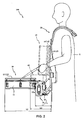
- Fig. 2 illustrates a side view of the electronic percussion instrument system of Fig. 1 viewed from a direction of an arrow II in Fig. 1 ;
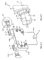
- Fig. 3(a) illustrates an attachment member for an electronic percussion instrument system according to an embodiment of the present invention
- Fig. 3(b) illustrates a cross-section drawing of the attachment member of Fig. 3(a) viewed along a line IIIb-IIIb in Fig. 3(a) ;
- Fig. 4(a) illustrates the attachment member of Fig. 3(a) viewed from a direction of an arrow IVa in Fig. 3(a) ;
- Fig. 4(b) illustrates a locking lever according to an embodiment of the present invention
- Fig. 5(a) illustrates a case according to an embodiment of the present invention
- Fig. 5(b) illustrates a rotating shaft section according to an embodiment of the present invention viewed from a direction of an arrow Vb in Fig. 5(a) ;
- Fig. 5(c) illustrates the case of Fig. 5(a) viewed from a direction of an arrow Vc in Fig. 5(a) ;
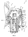
- Fig. 6 is a cross-section drawing of the case of Fig. 5(a) viewed along a line VI-VI in Fig. 5(a) ;
- Fig. 7 is a block diagram showing an electrical configuration of an electronic percussion instrument according to an embodiment of the present invention.
- Fig. 8 illustrates an example of a previous type of electronic percussion instrument and case.
- Figs. 1 and 2 illustrate an electronic percussion instrument system 100 according to an embodiment of the present invention.
- the electronic percussion instrument system 100 may be a percussion instrument for marching, or the like.
- the electronic percussion instrument system 100 may comprise, but is not limited to, an electronic percussion instrument 10, a holding fixture 20, and an operating device 1.
- the electronic percussion instrument 10 may be for example, but not limited to, an electronic drum, or other electronic percussion instrument, which can be played with or otherwise performed upon using a drum stick, or the like.
- the electronic percussion instrument 10 may comprise, but is not limited to, a main body 11 and a pad 12.
- the pad 12 may be arranged on a top surface of the main body 11.
- the electronic percussion instrument 10 may be arranged a specified distance L1 away from a performer-user X such that the pad 12 can be struck easily by the performer-user X.
- the main body 11 may be a body for serving as a frame of the electronic percussion instrument 10.
- the main body 11 may have a cylindrical shape.
- the main body 11 may be formed from a resin material.
- the pad 12 may include a circular head 13.
- the head 13 may be made of a permeable cloth, such as mesh, or the like.
- the pad 12 and the head 13 may be arranged across a top surface of the main body 11.
- a ring-shaped rim 14 may surround the head 13. Vibrations may be produced by striking the head 13 and/or the rim 14.
- the vibrations produced by striking the rim 14 may be detected by a rim sensor 101 (refer to Fig. 7 ).
- the vibrations produced by striking the head 13 may be detected by a head sensor 102 (refer to Fig. 7 ).
- an angle of the striking surface of the pad 12 may be adjustable, for example by turning a knob, or the like (discussed later).
- the operating device 1 may comprise a case 40 and an attachment number 30.
- the main body 11 of the electronic percussion instrument 10 may be operatively connected to the case 40, for example with a bracket 12a, or the like. Accordingly, the main body 11 may be supported by the case 40.
- the bracket 12a may be shaped, for example, like a reversed squared "C" when viewed from a side.
- the holding fixture 20 (or a supporting member) may be configured to support the case 40, and thus the electronic percussion instrument 10.
- the holding fixture 20 may comprise a shoulder section.
- the shoulder section of the holding fixture 20 may be for allowing the performer-user X to wear or otherwise support the holding fixture 20.
- An end of the holding fixture 20 opposite the shoulder section of the holding fixture 20 may be connected to the attachment member 30. Accordingly, the performer-user X may be able to use the holding fixture 20 to hold the electronic percussion instrument 10, the attachment member 30, and the case 40.
- the performer-user X may be able to strike the pad 12 of the electronic percussion instrument 10 while marching, parading, or otherwise performing.
- the shoulder section of the holding fixture 20 may be shaped in a shape of a reverse letter "J" when viewed from a side.
- the end of the holding fixture 20 opposite the shoulder section of the holding fixture 20 may be "J"-shaped and may extend from the shoulder section of the holding fixture 20 and be attached to the attachment member 30.
- the case 40 may be arranged between the holding fixture 20 and the electronic percussion instrument 10.
- the case 40 may have a box-like shape, which may allow for maintaining rigidity of the case 40.
- the case 40 may house an electronic circuit K, which may be for processing the signal generated by striking the pad 12.
- the case 40 may be attached to the electronic percussion instrument 10.
- the case 40 and the attachment member 30 may be configured as a single unit.
- the attachment member 30 may be attached to the holding fixture 20.
- the electronic percussion instrument 10 may be operatively connected to the holding fixture 20 such that a performer-user X wearing the holding fixture 20 may be able to support the attached electronic percussion instrument 10.
- the case 40 and the attachment member 30 are not configured as a single unit, but are connected together.
- the main body 11 and the pad 12 of the electronic percussion instrument 10 may be arranged at a location that allows the performer-user X to easily strike the pad 12.
- a space may be provided between the electronic percussion instrument 10 and the holding fixture 20. If the electronic percussion instrument 10 is too close to the performer-user X, the performer-user X may have difficulty striking the pad 12.
- the case 40 may be provided in the space between the holding fixture 20 and the electronic percussion instrument 10. In such embodiments, because the cause 40 may be arranged closer to the performer-user X than the electronic percussion instrument 10, buttons, switches, or the like provided on the case 40 (discussed later) are easily accessible to the performer-user X.
- portions of the electronic percussion instrument system 100 may be configured to be moveable or otherwise rotatable toward the performer-user X.
- the case 40 and the electronic percussion instrument 10 can be moved above the attachment member 30 by rotating the case 40 (and the electronic percussion instrument 10) upward toward the performer-user X relative to the attachment member 30.
- the case 40 and the electronic percussion instrument 10 may be placed in close proximity to the performer-user X.
- the rotating shaft 41b may serve as a pivoting member to allow the case 40 and the electronic percussion instrument 10 to rotate or pivot up and down.
- the electronic percussion instrument system 100 may protrude in front of the performer-user a distance L2.
- the case 40 and the electronic percussion instrument 10 are rotated upward relative to the attachment member 30 the electronic percussion instrument 10 may protrude in front of the performer a distance L3, which may be less than the distance L2.
- Figs. 3(a), 3(b) , 4(a), and 4(b) illustrate an example of the attachment member 30 and portions thereof according to an embodiment of the present invention.
- the attachment member 30 may be for attaching the case 40 to the holding fixture 20.
- the attachment member 30 may be linked to the end of the holding fixture 20 and may be held on the body of the performer-user X.
- the attachment member 30 may serve as a universal adapter, or the like, to attach the case 40 to the holding fixture 20.
- the attachment member 30 may include, but is not limited to, a pair of holding sections 31, a plate section 32, and locking levers 33.
- the holding sections 31 may be attached to the holding fixture 20.
- the plate section 32 may be provided to connect the pair of holding sections 31.
- the adjusing levers 33 may be supported in the holding sections 31.
- the pair of holding sections 31 and the fixing levers 33 may be identical on the left side and the right side, an explanation will be given regarding the holding section 31 and the locking lever on the left side in Fig. 3(a) and Fig. 3(b) , while an explanation regarding the holding section 31 and the locking lever on the right side in Fig. 3(a) and Fig. 3(b) will be omitted.
- the holding section 31 may be a member of any suitable shape, such as a polygonal member, connected to the plate section 32.
- the holding section 31 may be configured to attach to the holding fixture 20.
- the holding section may include an insertion hole 31a for inserting an end of the holding fixture 20.
- the holding section 31 may be for supporting a rotating shaft 41 b (discussed later).
- the holding section 31 may include a first groove 31b, in a shape of a "U", for supporting the rotating shaft 41 b.
- the holding section 31 may include a second groove 31c adjacent the first groove 31b.
- the second groove 31c may extend further into the holding section 31 than the first groove 31b.
- the second groove 31 c may be for supporting the locking lever 33.
- the plate section 32 may be attached or otherwise fastened to the rear surfaces of the holding sections 31, in any suitable manner, such as, but not limited to, bolts 32b, screws, or the like.
- the plate section 32 may include an adjusting bolt 32a, screw, or the like, to adjust an angle of the striking surface of the pad 12 (refer to Fig. 1 ) by turning the adjusting bolt 32a.
- the adjusting bolt 32a may be inserted through a hole in the plate section 32.
- a shaft portion of the adjusting bolt 32a may be operatively connected to the case 40 such that adjustment of the adjusting bolt 32a changes the angle of the case 40, which changes the angle of the electronic percussion instrument 10 (refer to Fig. 1 ) and the attached pad 12 (refer to Fig. 1 ).
- the shaft portion of the adjusting bolt 32a may be configured and/or selected such that a length of the shaft portion of the adjusting bolt 32a in the axial direction may be adjustable.
- an end of the shaft portion of the adjusting bolt 32a may be in contact with the case 40 to further support the case 40 with the holding fixture 20. In some embodiments, the end of the shaft portion of the adjusting bolt 32a may be in contact with a padding section 49a (refer to Fig. 6 ) of the case 40.
- a bias member such as a spring S or the like, may be configured to provide a bias force upon the locking lever 33.
- the spring S may be housed in a first portion of the insertion hole 31a, while the end of the holding fixture 20 may be fitted in a second portion of the insertion hole 31a opposite the first portion of the insertion hole 31a.
- the locking lever 33 may be supported by the holding section 31, for example in the second groove 31c. A bottom portion of the spring S may be in contact with the bolt 32b. The locking lever 33 may be biased toward a top end of the spring S (the top in Fig. 3(b) ).
- the holding fixture 20 fitted in the insertion hole 31a may be inserted into the insertion hole 31a to a position in which the holding fixture 20 contacts the bolt 32b.
- the holding fixture 20 may be secured in the insertion hole 31a, for example with a screw, bolt, or the like.
- the locking lever 33 may be positioned in the holding section 31.
- the locking lever 33 and/or the holding section 31 may be configured to prevent the locking lever 33 from falling out or out from the second groove 31c.
- the second groove 31c may be further received into the holding section 31 than the first groove 31b. Therefore, the locking lever 33 may be placed in the second groove 31 c (the upper left side in Fig. 3 (a) ) and abutted against the wall in which the first groove 31b is formed to prevent the locking lever 33 from falling out or otherwise passing through the first groove 31b.
- the second groove 31c may have a cross section in a direction perpendicular to an axis O1 of the rotating shaft section 41.
- the second groove 31 c may be formed in a shape of a circular arc that may surround at least half of an outer peripheral surface of the locking lever 33 when the locking lever 33 is in the second groove 31c, which may prevent the locking lever 33 from falling out or being otherwise removed out the top of the second groove 31c (i.e., in the direction perpendicular to the axis O1 of the rotating shaft 41b).
- Fig. 4(b) illustrates the locking lever 33 according to an embodiment of the present invention.
- the locking lever 33 may be configured to retain a portion of the rotating shaft section 41 (refer to Fig. 3 ) in the second groove 31c.
- the locking lever 33 may have a main body 33a.
- the main body 33a may be cylindrically shaped and may have a diameter that is larger than a diameter of the rotating shaft 41 b of the rotating shaft section 41 (refer to Fig. 3 ).
- the locking lever 33 may include a collar 33c attached to an end of the main body 33a.
- the collar 33c may have a diameter that is larger than the diameter of the main body 33a.
- the locking lever 33 may include a protrusion, such as a knob 33d, or the like, attached to an end of the collar 33c, such that the collar 33c is positioned between the main body 33a and the knob 33d.
- the knob 33d may be elliptically shaped, for example, with a short end and a long end.
- the knob 33d may be for allowing the performer-user X to grip the knob 33d and turn it clockwise or counter clockwise at least between a first position and a second position. In the first position, for example, the knob 33d may be perpendicular to the ground with the long end of the knob 33d located above the main body 33a of the locking lever 33 (the left knob 33d of Fig. 3(a) ). In the second position, for example, the knob 33d may be perpendicular to the ground with the long end of the knob 33d located below the main body 33a of the locking lever (the right knob 33d of Fig. 3(a) ).
- the locking lever 33 may be configured to receive at least a portion of the rotating shaft section 41.
- the locking lever 33 may include a receiving portion 33e located on an end of the main body 33a opposite from the end of the main body 33a attached to the collar 33c.
- the receiving portion 33e may be configured to receive a complementing portion 41c of the rotating shaft section 41.
- the complementing portion 41 c of the rotating shaft section 41 may be a pillow block, or the like, configured to be fitted into the receiving portion 33e of the locking lever 33.
- at least one of the receiving portion 33e of the locking lever 33 and the complementing portion 41c of the rotating shaft section 41 may be made of metal, resin, or the like.
- the locking lever 33 can be rotated with respect to the holding section 31 at least between the first position and the second position to lock and/or release the attachment member 30 to the case 40.
- the locking lever 33 When the locking lever 33 is in the first position (e.g., the long end of the knob 33d is above the main body 33a of the locking lever 33), a portion of the rotating shaft section 41 can be inserted into the holding section 31.
- the rotating shaft section 41 In a case where the locking lever 33 is in the second position (e.g., the long end of the knob 33d is below the main body 33a of the locking lever 33) and the rotating shaft section 41 is inserted the holding section 31, the rotating shaft section 41 may be prevented from being removed from the second groove 31c.
- the performer-user X may turn the knob 33d clockwise (or counterclockwise) from the first position to the second position.
- the knob 33d shown on the right side in Fig. 3(a) illustrates a knob 33d in the second position (i.e., a locked position).
- the knob 33d can be maintained in the second position with a bias force provided by the spring S or other suitable bias member.
- the main body 33a may include a spring groove 33f, a positioning groove 33g, and an indicator groove 33b.
- the spring groove 33 f may be a concavity formed on an outer surface of the main body 33a extending a specified length in the direction of the axis 02 of the main body 33a.
- the spring groove 33f may be for receiving the spring S (refer to Fig. 3(b) ).
- the positioning groove 33g may be a semi-circular concavity formed on the outer surface of the main body 33a and may be positioned between the spring groove 33f and the collar 33c.
- the indicator groove 33b may be a semi-circular concavity formed on the outer surface of the main body 33a opposite from the positioning groove 33g with a cross-section that may be perpendicular to the axis of the main body section 33a.
- the locking lever 33 may be configured to be at least partially rotatable within the holding section 31 at least between the first position and the second position.
- a fastener such as a screw 33i, or the like, may be screwed into the rear surface of the holding section 31 to enter the positioning groove 33g of the locking lever 33. Accordingly, the locking lever 33 may be rotatable relative to the screw 33i with the positioning groove 33g moving along the screw 33i.
- the indicator groove 33b may include an indicator, such as a label (not shown) for indicating whether the fixed lever 33 is in the first position (e.g., unlocked position) or the second position (e.g., locked position).
- the indicator groove 33b may come into view allowing the performer-user X to look into the indicator groove 33b and see the now exposed label (not shown) to indicate that the locking lever 33 is locked (or unlocked).
- movement of the knob 33d to the second position may cause the spring S to engage the locking lever 33 to maintain the locking lever 33 in the second position.
- the spring S may be for applying a bias force against the locking lever 33.
- the spring S may be able to expand and engage the locking lever 33 at the spring groove 33f to retain the locking lever 33 in place.
- a sound may be produced, such as a clicking sound or a snapping sound.
- a clicking sensation may be produced when the spring S engages the spring groove 33f. Accordingly, the performer-user X may be able to confirm the locking and releasing of the locking lever 33 (i.e., movement between the first and second positions).
- the case 40 may include a main body 40a.
- the main body 40a of the case 40 may have a cylindrical shape.
- the main body 40a (or the case 40 in its entirety) may be formed from an extruded molded material.
- the material may be a metal, such as aluminum or the like.
- the case 40 may include an upper reinforcing plate 43 and a lower reinforcing plate 44 such that the main body 40a is arranged between the upper reinforcing plate 43 and the lower reinforcing plate 44.
- the upper reinforcing plate 43 and the lower reinforcing plate 43 may be attached or otherwise fastened in any suitable manner to the main body, such as with bolts 40b, screws, or the like.
- the upper reinforcing plate 43 may be a rigid material, made of metal, or the like.
- the upper reinforcing plate 43 may be a metal steel plate, such as a zinc-plated steel plate.
- the upper reinforcing plate 43 may have a flat plate section 43a, which may me formed in approximately a same size and configuration of the main body 40a.
- the upper reinforcing plate 43 may include a rear protrusion 43c, which may protrude from a rear side of the flat plate section 43a (i.e., a side closest to the performer-user X when the performer-user X is wearing the holding fixture 20, for example).
- the upper reinforcing plate 43 may include a front protrusion 43b, which may protrude from a front side of the flat plate section 43a (i.e., a side opposite the rear protrusion 43c).
- the flat plate section 43a, the front protrusion 43b, and the rear protrusion 43c may be formed integral to one another.
- the vibrations due to the striking of the pad 12 may be transmitted or otherwise distributed to the holding fixture 20 through the front protrusion 43b, the flat plate section 43a, and the rear protrusion 43c. This may substantially inhibit the vibrations from being transmitted to the main body 40a of the case 40 and any circuitry housed within the main body 40a.
- the rotating shaft section 41 may be operatively connected to the case 40.
- a pair of support members 41a may extend upward from the rear protrusion 43c of the upper reinforcing plate 43.
- the support members 41a may be integral to the rear protrusion 43c of the upper reinforcing plate 43.
- the rotating shaft 41 b may extend though the support members 41 a such that the rotating shaft 41 b may be able to rotate freely.
- the support members 41a may each have an opening (in the direction of axis O1 of the rotating shaft 41) in which the rotating shaft 41 b can be placed to support the rotating shaft 41 b.
- the flat plate section 43a may have an opening.
- Each end of the rotating shaft 41 b may include the complementing portion 41c, which as discussed may be inserted into the fixing lever 33.
- the portions of the ends of the rotating shaft 41 b that protrude from the support members 41a may be fitted with the complementing portion 41c.
- the complementing portion 41c may be roughly hat shaped (i.e., have a "U"-shaped cross-section). Accordingly, the complementing portion 41c may be supported by the first groove 31b of the holding section 31 and the receiving portion 33e of the locking lever 33 (refer to Fig. 3(a) ).
- An outer covering 41 d may enclose at least a portion of the rotating shaft 41 b, for example the portion of the rotating shaft 41 b between the support members 41a.
- the outer covering 41d may be formed integral to the operating panel 42.
- the operating panel 42 and the outer covering 41d may be attached to the main body 40a of the case 40 as shown in Fig. 5(a) .
- the case 40 may be attached to the electronic percussion instrument, for example with brackets 12a.
- the brackets 12a may be attached to attachment pieces 45, which may be attached to the case 40, in any suitable manner, such as with bolts, screws, or the like.
- the brackets 12a may be arranged such that top surfaces of the attachment pieces 45 are in contact with bottom surfaces of the brackets 12a.
- the brackets 12a for example, may be attached to a top surface of the front protrusion 43b.
- the case 40 may include a circuit board 47 and a battery (not shown) located within the main body 40a of the case 40.
- the battery (not shown) may be supported in a battery housing 48 that is disposed on an inside surface of the main body 40a of the case 40.
- the circuit board 47 may include an electronic circuit K (refer to Fig. 7 ).
- the circuit board 47 may be attached or otherwise fastened in any suitable manner to an inside surface of the case 40, for example with a plurality of bolts 47a, screws, or the like.
- the circuit board 47 may be arranged on the inside surface of the main body 40a of the case 40 such that the circuit board 47 is perpendicular to the striking surface of the rim 14 (the head 13). In such embodiments, the circuit board 47 may be approximately perpendicular to a direction of vibrations produced from striking the pad 12 to mitigate damage to the circuit board 47 from said vibrations.
- the case 40 may include a bottom member 49 that may be fit onto a lower portion of the main body 40a.
- the bottom member 49 may include the padding 49a (refer to Fig. 5(c) ) that may extend away from the bottom member 49 and/or the main body 40a of the case 40.
- the padding 49a may extend toward the performer-user X to prevent the performer-user X from contacting the rigid surface of the case 40.
- the case 40 may have a vertical dimension that is longer than a vertical dimension of the electronic percussion instrument 10 and a vertical dimension of the attachment member 30.
- the case 40 may include an operating panel 42 that may include a plurality of controls, such as, but not limited to, buttons, switches, knobs, sliders, and the like.
- the operating panel 42 may include, but is not limited to, memory buttons 42a, an instrument button 42b, a power button 42c for turning on and off the power, a beat button 42d, a select knob 42e for selecting various parameters and the like, a metronome button 42f for turning on and off a metronome (not shown), a coach button 42g for toggling on and off a "coach" mode, and a display area 42h.
- the plurality of switches 42a to 42g may be arranged on a top surface of an operating panel 42.
- the plurality of switches 42a to 42g may be positioned lower than the top surface of the rim 14 (refer to Fig. 1 ), which may be the highest portion of the pad 12 (refer to Fig. 1 ).
- the plurality of switches 42a to 42g may be positioned lower than the head 13 (refer to Fig. 1 ), which may be arranged below the rim 14 (refer to Fig. 1 ). Accordingly, accidental striking of one of the plurality of switches 42a to 42g may be inhibited.
- the operating panel 42 is configured having one or more memory buttons 42a.
- the memory buttons 42a may be for selecting various parameters, such as pitch, timbres and effects, and the like that correspond to each memory button 42a.
- the various parameters may be set and stored in advance.
- the instrument button 42b may toggle between a live mode and a setting mode.
- the setting mode may be set.
- the timbre and various other parameters may be set using the select knob 42e, for example.
- "live mode" may be initiated.
- the live mode for example, only the memory buttons 42a and the power button 42c may be operable. Accordingly, other functions, such as use of the metronome button 42f, the coach button 42g, or the like may be disabled.
- the beat button 42d may allow for various kinds of parameters (e.g., beat, tempo, and the like) of the metronome mode to be edited.
- parameters e.g., beat, tempo, and the like
- the system edit mode may be initiated.
- various kinds of parameters e.g., pad sensitivity, a threshold value for trigger detection, and the like. These various parameters may be set using the select knob 42e.
- the coach button 42g may be for toggling on and off a coaching mode.
- various parameters may be displayed on the display screen 42h, such as striking force, striking timing matching the metronome, and the like. Accordingly, the performer-user X may be able to practice striking of the pad in conjunction with the coach mode.
- the main body 40a may include a trigger in jack 40h for inputting the striking signal generated from striking the pad 12.
- the main body 40a may include a power supply jack, for example for a DC power supply voltage.
- the main body 40a may include volume controls, such as a headphone volume control 40j.
- the main body 40a may include a headphone jack 40k and/or other output jacks 40m for outputting musical tones to an external speaker or headphone.
- a cable (not shown) for connecting a speaker system with a built-in amplifier (not shown) may be connected to the output jack 40m.
- Fig. 7 is a block diagram that shows an electrical configuration of the electronic percussion instrument 10.
- the electronic percussion instrument 10 may include, but is not limited to, a rim sensor 101 and a head sensor 102.
- the case 40 may include, but is not limited to, an input terminal (not shown), a first waveform producing circuit 104, a second waveform producing circuit 105, an A/D converter 106, a CPU 107, ROM 108, RAM 109, a sound source 110, an amplifier 111, and one or more output jacks 40k, 40m.
- the A/D converter 106, the CPU 107, the ROM 108, the RAM 109, and the sound source 110 may be connected to a bus 120.
- the CPU 107 may be a processor for executing various control programs stored in the ROM 108.
- the ROM 108 may be memory that cannot be rewritten and that stores the various control programs.
- the RAM 109 may be random access memory with a work area for temporarily storing variables and the like when the various control programs are executed by the CPU 107 and the like.
- the case 40 may include a pitch memory for storing pitches, and pitches of stored timbres, and the like that correspond to each of the memory buttons 42a. Incidentally, power may be supplied to the RAM 109 by the battery and the stored contents within may be maintained even when the power has been turned off by the power button 42c.
- the rim sensor 101 and/or the head sensor 102 may be for detecting vibrations created by striking the electronic percussion instrument 10, for example, with a drumstick.
- a musical tone system (not shown) may control a sound source based on detection signals of the rim sensor 101 and/or the head sensor 102. Accordingly, the musical tone system (not shown) may be configured to generate a musical tone in conformance with a striking of the electronic percussion instrument 10. In some embodiments, the musical tone generated by the musical tone system (not shown) may be emitted from a speaker device (not shown) via an amplifier 111.
- Electrical signals detected by each of the sensors 101 and 102 may be input respectively to the first waveform producing circuit 104 and the second waveform producing circuit 105 using a connecting cable, for example.
- the electrical signals may be detected by each of the waveform producing circuits 104 and 105.
- Envelopes may be extracted and the envelopes may be sampled at a specified sampling frequency and output to the A/D converter 106.
- the sampled signals may be each quantized by the A/D (analog-digital) converter 106, and may be converted into digital signals, and output to the CPU 107.
- the CPU 107 may make a determination from the digital signals as to whether or not a striking has occurred.
- the CPU 107 may generate various information, such as velocity information and striking position information, note ON information, etc.
- the CPU 107 may output the various information to instruct a production of a musical tone to the sound source 110.
- the sound source 110 may produce a sound, such as a percussion instrument sound, or the like in conformance with the note ON information, for example, inputted into the sound source 110.
- the musical tone waveforms for each of the percussion instruments and the like may be stored in the memory. The stored waveforms may be read out. In addition, frequency characteristics, amplitude, and the like may be controlled, and accordingly the musical tone may be produced.
- the musical tone signal outputted from the sound source 110 may be amplified by the amplifier 111 and may be outputted from the one or more output jacks 40k, 40m, such as a headphone jack, or the like.
- the attachment member 30 and the case 40 may be configured as separate units. In other embodiments, the attachment member 30 and the case 40 may be formed as a single unit. In such embodiments, for example, the case 40 may be attached to the attachment member 30
- the case 40 may be supported by the holding fixture 20 via the attachment member 30.
- a musical tone may be produced from striking the pad 12.
- the electronic percussion instrument system 100 may include a transmitter (not shown) for transmitting a striking signal produced from striking the pad 12 to a remotely located sound source system (not shown).
- the transmitted signal may be a musical tone signal or a musical tone control digital signal, such as a MIDI, or the like, that is converted into a striking signal.
- the electronic percussion instrument system 100 may include a musical tone generation circuit (not shown), for example inside the pad 12.
- the electronic percussion instrument system 100 may include an effector (not shown) for applying timbre and sound field changes to the musical tone signal from the pad 12.
Landscapes
- Physics & Mathematics (AREA)
- Engineering & Computer Science (AREA)
- Acoustics & Sound (AREA)
- Multimedia (AREA)
- Electrophonic Musical Instruments (AREA)
- Auxiliary Devices For Music (AREA)
Description
- The invention relates to an operating device with an electronic percussion element.
-
US 2006/0272490 A1 discloses an electro-acoustically amplified drum mixer having a drumhead with a drum shell, and having a compressor/limiter attached to the drum via two mounting brackets. - Japanese PCT translation
H11-502640 -
Fig. 8 of the present application illustrates an example of a previous type of electronic percussion instrument and case. As shown inFig. 8 , anelectronic percussion instrument 200 has ahead 213, which is formed with a flexible, permeable material, such as mesh and the like, arim 214, which is arranged surrounding thehead 213, and acase 210 containing an electronic circuit (not shown). - However, the
electronic percussion instrument 200 is meant to be stationary, for example, attached to a snare stand (not shown) and placed on the floor. Furthermore, theelectronic percussion instrument 200 is not adapted to be fastened to a holding fixture worn by a user for marching and the like to allow a musical performance to be conducted while parading and performing. - Embodiments of the present invention relate to an operating device for use with an electronic percussion instrument and, particular embodiments relate to an operating device that can be attached to and used with an electronic percussion instrument, and to a holding fixture supported by a performer-user for marching and the like to allow a musical performance to be conducted while parading and performing.
- An operating device in accordance with an embodiment of the present invention as described in
claim 1. - Because the case is operatively connected to the holding fixture and the electronic percussion instrument, the electronic percussion instrument can be operatively connected to or otherwise supported by the holding fixture as well. Thus, a performer-user can conduct a musical performance with the electronic percussion instrument while parading and performing, for example, while marching and the like.
- In addition, rigidity may be maintained because the case is formed in a box form. Thus, the electronic percussion instrument may be stabilized and fastened to the case and the holding fixture. Moreover, the case may be arranged between the holding fixture supported on the body of the performer-user such that the case may be arranged closer to the performer-user than the electronic percussion instrument.
- Further embodiments of the invention are described in the dependent claims.
- In various embodiments, an operating panel may be provided on the case. The operating panel may have a plurality of controls. In some embodiments, the plurality of controls may be arranged on the operating panel at a position lower than the striking surface of the pad. Therefore, because the operators may be arranged in a place where the performer-user's hand can easily reach, the operability of the operators may be improved. Accordingly, inadvertent striking of the operators may be mitigated. In addition, because the case may include an operating panel comprising a plurality of operators positioned lower than the striking surface of the pad, mistakes due to the performer-user inadvertently striking the case may be mitigated.
- The electronic percussion instrument may be arranged such that a specified space is provided between the electronic percussion instrument and the holding fixture. This may effectively use space between the electronic percussion instrument and the holding fixture.
- Because the printed circuit board is attached to the housing and arranged perpendicular to the striking surface of the pad, damage to the printed circuit board may be mitigated. In other words, because the direction in which the vibrations produced by the striking of the pad and the printed circuit board are roughly perpendicular, the printed circuit board may be less likely to bend or warp, and thus damage to the printed circuit board from the vibrations may be reduced. Additionally, placing the case, which contains the electronic circuit for processing a signal produced by striking the pad, in the specified space may further effectively use the specified space provided between the electronic percussion instrument and the holding fixture. The instrument attachment member, the holding fixture attachment member, and the upper reinforcing plate are formed as a single unit.
- Accordingly, because the instrument attachment member, the holding fixture attachment member, and the upper reinforcing plate may be configured as a single unit, the vibrations due to the striking of the pad may be transmitted to the holding fixture via the instrument attachment member, the upper reinforcing plate, and the holding fixture attachment member. Therefore, the relevant vibrations transmitted to the main body of the case containing the circuit board may be reduced to mitigate damage to the circuit board.
- In various embodiments, the percussion instrument and the casing may be configured to be moveable relative to the supporting member.
- In various embodiments, the casing may comprise an operating panel having a plurality of controls. In some embodiments, the plurality of controls may be positioned at a position lower than the striking surface of the percussion instrument.
- The circuit board may have a longitudinal dimension. The circuit board may be arranged within the casing such that the longitudinal dimension of the circuit board is approximately perpendicular to the striking surface of the percussion instrument.
-
Fig. 1 illustrates an electronic percussion instrument system according to an embodiment of the present invention; -
Fig. 2 illustrates a side view of the electronic percussion instrument system ofFig. 1 viewed from a direction of an arrow II inFig. 1 ; -
Fig. 3(a) illustrates an attachment member for an electronic percussion instrument system according to an embodiment of the present invention; -
Fig. 3(b) illustrates a cross-section drawing of the attachment member ofFig. 3(a) viewed along a line IIIb-IIIb inFig. 3(a) ; -
Fig. 4(a) illustrates the attachment member ofFig. 3(a) viewed from a direction of an arrow IVa inFig. 3(a) ; -
Fig. 4(b) illustrates a locking lever according to an embodiment of the present invention; -
Fig. 5(a) illustrates a case according to an embodiment of the present invention; -
Fig. 5(b) illustrates a rotating shaft section according to an embodiment of the present invention viewed from a direction of an arrow Vb inFig. 5(a) ; -
Fig. 5(c) illustrates the case ofFig. 5(a) viewed from a direction of an arrow Vc inFig. 5(a) ; -
Fig. 6 is a cross-section drawing of the case ofFig. 5(a) viewed along a line VI-VI inFig. 5(a) ; -
Fig. 7 is a block diagram showing an electrical configuration of an electronic percussion instrument according to an embodiment of the present invention; and -
Fig. 8 illustrates an example of a previous type of electronic percussion instrument and case. -
Figs. 1 and2 illustrate an electronicpercussion instrument system 100 according to an embodiment of the present invention. The electronicpercussion instrument system 100 may be a percussion instrument for marching, or the like. The electronicpercussion instrument system 100 may comprise, but is not limited to, anelectronic percussion instrument 10, aholding fixture 20, and anoperating device 1. - In some embodiments, the
electronic percussion instrument 10 may be for example, but not limited to, an electronic drum, or other electronic percussion instrument, which can be played with or otherwise performed upon using a drum stick, or the like. - The
electronic percussion instrument 10 may comprise, but is not limited to, amain body 11 and apad 12. Thepad 12 may be arranged on a top surface of themain body 11. Theelectronic percussion instrument 10 may be arranged a specified distance L1 away from a performer-user X such that thepad 12 can be struck easily by the performer-user X. - The
main body 11 may be a body for serving as a frame of theelectronic percussion instrument 10. In some embodiments, themain body 11 may have a cylindrical shape. In further embodiments, themain body 11 may be formed from a resin material. - The
pad 12 may include acircular head 13. Thehead 13 may be made of a permeable cloth, such as mesh, or the like. Thepad 12 and thehead 13 may be arranged across a top surface of themain body 11. A ring-shaped rim 14 may surround thehead 13. Vibrations may be produced by striking thehead 13 and/or therim 14. The vibrations produced by striking therim 14 may be detected by a rim sensor 101 (refer toFig. 7 ). The vibrations produced by striking thehead 13 may be detected by a head sensor 102 (refer toFig. 7 ). In some embodiments, an angle of the striking surface of the pad 12 (i.e., the angle with respect to the ground, or the angle with respect to the performer-user X) may be adjustable, for example by turning a knob, or the like (discussed later). - The operating
device 1 may comprise acase 40 and anattachment number 30. Themain body 11 of theelectronic percussion instrument 10 may be operatively connected to thecase 40, for example with abracket 12a, or the like. Accordingly, themain body 11 may be supported by thecase 40. In some embodiments, thebracket 12a may be shaped, for example, like a reversed squared "C" when viewed from a side. - The holding fixture 20 (or a supporting member) may be configured to support the
case 40, and thus theelectronic percussion instrument 10. In some embodiments, the holdingfixture 20 may comprise a shoulder section. The shoulder section of the holdingfixture 20 may be for allowing the performer-user X to wear or otherwise support the holdingfixture 20. An end of the holdingfixture 20 opposite the shoulder section of the holdingfixture 20 may be connected to theattachment member 30. Accordingly, the performer-user X may be able to use the holdingfixture 20 to hold theelectronic percussion instrument 10, theattachment member 30, and thecase 40. Thus, for example, allowing the performer-user X to be able to strike thepad 12 of theelectronic percussion instrument 10 while marching, parading, or otherwise performing. - In one exemplary embodiment, the shoulder section of the holding
fixture 20 may be shaped in a shape of a reverse letter "J" when viewed from a side. The end of the holdingfixture 20 opposite the shoulder section of the holdingfixture 20 may be "J"-shaped and may extend from the shoulder section of the holdingfixture 20 and be attached to theattachment member 30. - The
case 40 may be arranged between the holdingfixture 20 and theelectronic percussion instrument 10. In some embodiments, thecase 40 may have a box-like shape, which may allow for maintaining rigidity of thecase 40. Thecase 40 may house an electronic circuit K, which may be for processing the signal generated by striking thepad 12. - In some embodiments, the
case 40 may be attached to theelectronic percussion instrument 10. Thecase 40 and theattachment member 30 may be configured as a single unit. Theattachment member 30 may be attached to the holdingfixture 20. Thus, theelectronic percussion instrument 10 may be operatively connected to the holdingfixture 20 such that a performer-user X wearing the holdingfixture 20 may be able to support the attachedelectronic percussion instrument 10. In other embodiments, thecase 40 and theattachment member 30 are not configured as a single unit, but are connected together. - The
main body 11 and thepad 12 of theelectronic percussion instrument 10 may be arranged at a location that allows the performer-user X to easily strike thepad 12. For example, a space may be provided between theelectronic percussion instrument 10 and the holdingfixture 20. If theelectronic percussion instrument 10 is too close to the performer-user X, the performer-user X may have difficulty striking thepad 12. Thus in some embodiments, thecase 40 may be provided in the space between the holdingfixture 20 and theelectronic percussion instrument 10. In such embodiments, because thecause 40 may be arranged closer to the performer-user X than theelectronic percussion instrument 10, buttons, switches, or the like provided on the case 40 (discussed later) are easily accessible to the performer-user X. - In some embodiments, portions of the electronic
percussion instrument system 100 may be configured to be moveable or otherwise rotatable toward the performer-user X. For example, as shown by the double dotted dashed line inFig. 2 , thecase 40 and theelectronic percussion instrument 10 can be moved above theattachment member 30 by rotating the case 40 (and the electronic percussion instrument 10) upward toward the performer-user X relative to theattachment member 30. Accordingly, thecase 40 and theelectronic percussion instrument 10 may be placed in close proximity to the performer-user X. In some embodiments, therotating shaft 41b may serve as a pivoting member to allow thecase 40 and theelectronic percussion instrument 10 to rotate or pivot up and down. - When the performer-user X is marching with or otherwise performing on the electronic
percussion instrument system 100, the electronicpercussion instrument system 100 may protrude in front of the performer-user a distance L2. When thecase 40 and theelectronic percussion instrument 10 are rotated upward relative to theattachment member 30 theelectronic percussion instrument 10 may protrude in front of the performer a distance L3, which may be less than the distance L2. By reducing the distance L2 to the distance L3, visibility of the performer-user X may be improved. -
Figs. 3(a), 3(b) ,4(a), and 4(b) illustrate an example of theattachment member 30 and portions thereof according to an embodiment of the present invention. As discussed, theattachment member 30 may be for attaching thecase 40 to the holdingfixture 20. For example, theattachment member 30 may be linked to the end of the holdingfixture 20 and may be held on the body of the performer-user X. In some embodiments, because dimensions of the holdingfixture 20 may vary depending on the manufacturer, theattachment member 30 may serve as a universal adapter, or the like, to attach thecase 40 to the holdingfixture 20. - In some embodiments, the
attachment member 30 may include, but is not limited to, a pair of holdingsections 31, aplate section 32, and locking levers 33. The holdingsections 31 may be attached to the holdingfixture 20. Theplate section 32 may be provided to connect the pair of holdingsections 31. The adjusing levers 33 may be supported in the holdingsections 31. - Because the pair of holding
sections 31 and the fixing levers 33 may be identical on the left side and the right side, an explanation will be given regarding the holdingsection 31 and the locking lever on the left side inFig. 3(a) and Fig. 3(b) , while an explanation regarding the holdingsection 31 and the locking lever on the right side inFig. 3(a) and Fig. 3(b) will be omitted. - With reference to
Figs. 3(a), 3(b) , and4(a) , the holdingsection 31 may be a member of any suitable shape, such as a polygonal member, connected to theplate section 32. The holdingsection 31 may be configured to attach to the holdingfixture 20. For example, the holding section may include aninsertion hole 31a for inserting an end of the holdingfixture 20. The holdingsection 31 may be for supporting arotating shaft 41 b (discussed later). For example, the holdingsection 31 may include afirst groove 31b, in a shape of a "U", for supporting therotating shaft 41 b. In further embodiments, the holdingsection 31 may include asecond groove 31c adjacent thefirst groove 31b. Thesecond groove 31c may extend further into the holdingsection 31 than thefirst groove 31b. Thesecond groove 31 c may be for supporting the lockinglever 33. - The
plate section 32 may be attached or otherwise fastened to the rear surfaces of the holdingsections 31, in any suitable manner, such as, but not limited to,bolts 32b, screws, or the like. Theplate section 32 may include an adjustingbolt 32a, screw, or the like, to adjust an angle of the striking surface of the pad 12 (refer toFig. 1 ) by turning the adjustingbolt 32a. For example, the adjustingbolt 32a may be inserted through a hole in theplate section 32. A shaft portion of the adjustingbolt 32a may be operatively connected to thecase 40 such that adjustment of the adjustingbolt 32a changes the angle of thecase 40, which changes the angle of the electronic percussion instrument 10 (refer toFig. 1 ) and the attached pad 12 (refer toFig. 1 ). The shaft portion of the adjustingbolt 32a may be configured and/or selected such that a length of the shaft portion of the adjustingbolt 32a in the axial direction may be adjustable. - In some embodiments, an end of the shaft portion of the adjusting
bolt 32a may be in contact with thecase 40 to further support thecase 40 with the holdingfixture 20. In some embodiments, the end of the shaft portion of the adjustingbolt 32a may be in contact with apadding section 49a (refer toFig. 6 ) of thecase 40. - In some embodiments, a bias member, such as a spring S or the like, may be configured to provide a bias force upon the locking
lever 33. For example, the spring S may be housed in a first portion of theinsertion hole 31a, while the end of the holdingfixture 20 may be fitted in a second portion of theinsertion hole 31a opposite the first portion of theinsertion hole 31a. - The locking
lever 33 may be supported by the holdingsection 31, for example in thesecond groove 31c. A bottom portion of the spring S may be in contact with thebolt 32b. The lockinglever 33 may be biased toward a top end of the spring S (the top inFig. 3(b) ). The holdingfixture 20 fitted in theinsertion hole 31a may be inserted into theinsertion hole 31a to a position in which the holdingfixture 20 contacts thebolt 32b. The holdingfixture 20 may be secured in theinsertion hole 31a, for example with a screw, bolt, or the like. - The locking
lever 33 may be positioned in the holdingsection 31. The lockinglever 33 and/or the holdingsection 31 may be configured to prevent the lockinglever 33 from falling out or out from thesecond groove 31c. For example, thesecond groove 31c may be further received into the holdingsection 31 than thefirst groove 31b. Therefore, the lockinglever 33 may be placed in thesecond groove 31 c (the upper left side inFig. 3 (a) ) and abutted against the wall in which thefirst groove 31b is formed to prevent the lockinglever 33 from falling out or otherwise passing through thefirst groove 31b. - In addition, the
second groove 31c may have a cross section in a direction perpendicular to an axis O1 of therotating shaft section 41. Thesecond groove 31 c may be formed in a shape of a circular arc that may surround at least half of an outer peripheral surface of the lockinglever 33 when the lockinglever 33 is in thesecond groove 31c, which may prevent the lockinglever 33 from falling out or being otherwise removed out the top of thesecond groove 31c (i.e., in the direction perpendicular to the axis O1 of therotating shaft 41b). -
Fig. 4(b) illustrates the lockinglever 33 according to an embodiment of the present invention. The lockinglever 33 may be configured to retain a portion of the rotating shaft section 41 (refer toFig. 3 ) in thesecond groove 31c. The lockinglever 33 may have amain body 33a. Themain body 33a may be cylindrically shaped and may have a diameter that is larger than a diameter of therotating shaft 41 b of the rotating shaft section 41 (refer toFig. 3 ). The lockinglever 33 may include acollar 33c attached to an end of themain body 33a. Thecollar 33c may have a diameter that is larger than the diameter of themain body 33a. - The locking
lever 33 may include a protrusion, such as aknob 33d, or the like, attached to an end of thecollar 33c, such that thecollar 33c is positioned between themain body 33a and theknob 33d. In some embodiments, theknob 33d may be elliptically shaped, for example, with a short end and a long end. Theknob 33d may be for allowing the performer-user X to grip theknob 33d and turn it clockwise or counter clockwise at least between a first position and a second position. In the first position, for example, theknob 33d may be perpendicular to the ground with the long end of theknob 33d located above themain body 33a of the locking lever 33 (theleft knob 33d ofFig. 3(a) ). In the second position, for example, theknob 33d may be perpendicular to the ground with the long end of theknob 33d located below themain body 33a of the locking lever (theright knob 33d ofFig. 3(a) ). - The locking
lever 33 may be configured to receive at least a portion of therotating shaft section 41. For example, the lockinglever 33 may include a receivingportion 33e located on an end of themain body 33a opposite from the end of themain body 33a attached to thecollar 33c. The receivingportion 33e may be configured to receive acomplementing portion 41c of therotating shaft section 41. For example, the complementingportion 41 c of therotating shaft section 41 may be a pillow block, or the like, configured to be fitted into the receivingportion 33e of the lockinglever 33. In some embodiments, at least one of the receivingportion 33e of the lockinglever 33 and the complementingportion 41c of therotating shaft section 41 may be made of metal, resin, or the like. - Accordingly, the locking
lever 33 can be rotated with respect to the holdingsection 31 at least between the first position and the second position to lock and/or release theattachment member 30 to thecase 40. When the lockinglever 33 is in the first position (e.g., the long end of theknob 33d is above themain body 33a of the locking lever 33), a portion of therotating shaft section 41 can be inserted into the holdingsection 31. In a case where the lockinglever 33 is in the second position (e.g., the long end of theknob 33d is below themain body 33a of the locking lever 33) and therotating shaft section 41 is inserted the holdingsection 31, therotating shaft section 41 may be prevented from being removed from thesecond groove 31c. Thus, to lock the lockinglever 33, the performer-user X may turn theknob 33d clockwise (or counterclockwise) from the first position to the second position. Theknob 33d shown on the right side inFig. 3(a) illustrates aknob 33d in the second position (i.e., a locked position). In some embodiments, theknob 33d can be maintained in the second position with a bias force provided by the spring S or other suitable bias member. - With reference to
Fig. 4(b) , in some embodiments, themain body 33a may include aspring groove 33f, apositioning groove 33g, and anindicator groove 33b. Thespring groove 33 f may be a concavity formed on an outer surface of themain body 33a extending a specified length in the direction of theaxis 02 of themain body 33a. Thespring groove 33f may be for receiving the spring S (refer toFig. 3(b) ). Thepositioning groove 33g may be a semi-circular concavity formed on the outer surface of themain body 33a and may be positioned between thespring groove 33f and thecollar 33c. Theindicator groove 33b may be a semi-circular concavity formed on the outer surface of themain body 33a opposite from thepositioning groove 33g with a cross-section that may be perpendicular to the axis of themain body section 33a. - In some embodiments, the locking
lever 33 may be configured to be at least partially rotatable within the holdingsection 31 at least between the first position and the second position. For example, a fastener, such as ascrew 33i, or the like, may be screwed into the rear surface of the holdingsection 31 to enter thepositioning groove 33g of the lockinglever 33. Accordingly, the lockinglever 33 may be rotatable relative to thescrew 33i with thepositioning groove 33g moving along thescrew 33i. - In further embodiments, the
indicator groove 33b may include an indicator, such as a label (not shown) for indicating whether the fixedlever 33 is in the first position (e.g., unlocked position) or the second position (e.g., locked position). For example, as the lockinglever 33 is rotated about the holdingsection 31, theindicator groove 33b may come into view allowing the performer-user X to look into theindicator groove 33b and see the now exposed label (not shown) to indicate that the lockinglever 33 is locked (or unlocked). - In some embodiments, movement of the
knob 33d to the second position may cause the spring S to engage the lockinglever 33 to maintain the lockinglever 33 in the second position. Accordingly, the spring S may be for applying a bias force against the lockinglever 33. When the lockinglever 33 is rotated to allow the spring S to contact thespring groove 33f, the spring S may be able to expand and engage the lockinglever 33 at thespring groove 33f to retain the lockinglever 33 in place. - In some embodiments, when the spring S engages the
spring groove 33f, a sound may be produced, such as a clicking sound or a snapping sound. In further embodiments, a clicking sensation may be produced when the spring S engages thespring groove 33f. Accordingly, the performer-user X may be able to confirm the locking and releasing of the locking lever 33 (i.e., movement between the first and second positions). -
Figs. 5(a)-5(c) and6 illustrate thecase 40 according to an embodiment of the present invention. Thecase 40 may include amain body 40a. In some embodiments, themain body 40a of thecase 40 may have a cylindrical shape. Themain body 40a (or thecase 40 in its entirety) may be formed from an extruded molded material. The material may be a metal, such as aluminum or the like. - In some embodiments, the
case 40 may include an upper reinforcingplate 43 and a lower reinforcingplate 44 such that themain body 40a is arranged between the upper reinforcingplate 43 and the lower reinforcingplate 44. The upper reinforcingplate 43 and the lower reinforcingplate 43 may be attached or otherwise fastened in any suitable manner to the main body, such as withbolts 40b, screws, or the like. - The upper reinforcing
plate 43 may be a rigid material, made of metal, or the like. For example, the upper reinforcingplate 43 may be a metal steel plate, such as a zinc-plated steel plate. The upper reinforcingplate 43 may have aflat plate section 43a, which may me formed in approximately a same size and configuration of themain body 40a. The upper reinforcingplate 43 may include arear protrusion 43c, which may protrude from a rear side of theflat plate section 43a (i.e., a side closest to the performer-user X when the performer-user X is wearing the holdingfixture 20, for example). The upper reinforcingplate 43 may include afront protrusion 43b, which may protrude from a front side of theflat plate section 43a (i.e., a side opposite therear protrusion 43c). - In some embodiments, the
flat plate section 43a, thefront protrusion 43b, and therear protrusion 43c, may be formed integral to one another. In such embodiments, because theflat plate section 43a, therear protrusion 43c, which may be linked to the holdingfixture 20, and thefront protrusion 43b, which may be linked to theelectronic percussion instrument 10, are formed integral to one another, the vibrations due to the striking of thepad 12 may be transmitted or otherwise distributed to the holdingfixture 20 through thefront protrusion 43b, theflat plate section 43a, and therear protrusion 43c. This may substantially inhibit the vibrations from being transmitted to themain body 40a of thecase 40 and any circuitry housed within themain body 40a. - In some embodiments, the
rotating shaft section 41 may be operatively connected to thecase 40. For example, a pair ofsupport members 41a may extend upward from therear protrusion 43c of the upper reinforcingplate 43. In some embodiments thesupport members 41a may be integral to therear protrusion 43c of the upper reinforcingplate 43. The rotatingshaft 41 b may extend though thesupport members 41 a such that the rotatingshaft 41 b may be able to rotate freely. For example, thesupport members 41a may each have an opening (in the direction of axis O1 of the rotating shaft 41) in which therotating shaft 41 b can be placed to support the rotatingshaft 41 b. In some embodiments, theflat plate section 43a may have an opening. - Each end of the
rotating shaft 41 b may include the complementingportion 41c, which as discussed may be inserted into the fixinglever 33. The portions of the ends of therotating shaft 41 b that protrude from thesupport members 41a may be fitted with the complementingportion 41c. In some embodiments, the complementingportion 41c may be roughly hat shaped (i.e., have a "U"-shaped cross-section). Accordingly, the complementingportion 41c may be supported by thefirst groove 31b of the holdingsection 31 and the receivingportion 33e of the locking lever 33 (refer toFig. 3(a) ). - An
outer covering 41 d may enclose at least a portion of therotating shaft 41 b, for example the portion of therotating shaft 41 b between thesupport members 41a. In some embodiments, theouter covering 41d may be formed integral to theoperating panel 42. For example, the operatingpanel 42 and theouter covering 41d may be attached to themain body 40a of thecase 40 as shown inFig. 5(a) . - As discussed in
Fig. 1 , thecase 40 may be attached to the electronic percussion instrument, for example withbrackets 12a. In some embodiments, thebrackets 12a may be attached toattachment pieces 45, which may be attached to thecase 40, in any suitable manner, such as with bolts, screws, or the like. For example, thebrackets 12a may be arranged such that top surfaces of theattachment pieces 45 are in contact with bottom surfaces of thebrackets 12a. In some embodiments, thebrackets 12a, for example, may be attached to a top surface of thefront protrusion 43b. - With reference to
Fig. 6 , thecase 40 may include acircuit board 47 and a battery (not shown) located within themain body 40a of thecase 40. The battery (not shown) may be supported in abattery housing 48 that is disposed on an inside surface of themain body 40a of thecase 40. - The
circuit board 47 may include an electronic circuit K (refer toFig. 7 ). Thecircuit board 47 may be attached or otherwise fastened in any suitable manner to an inside surface of thecase 40, for example with a plurality ofbolts 47a, screws, or the like. In some embodiments, thecircuit board 47 may be arranged on the inside surface of themain body 40a of thecase 40 such that thecircuit board 47 is perpendicular to the striking surface of the rim 14 (the head 13). In such embodiments, thecircuit board 47 may be approximately perpendicular to a direction of vibrations produced from striking thepad 12 to mitigate damage to thecircuit board 47 from said vibrations. - In addition, as is shown in
Fig. 6 , thecase 40 may include abottom member 49 that may be fit onto a lower portion of themain body 40a. Thebottom member 49 may include thepadding 49a (refer toFig. 5(c) ) that may extend away from thebottom member 49 and/or themain body 40a of thecase 40. For example, thepadding 49a may extend toward the performer-user X to prevent the performer-user X from contacting the rigid surface of thecase 40. - In some embodiments, the
case 40 may have a vertical dimension that is longer than a vertical dimension of theelectronic percussion instrument 10 and a vertical dimension of theattachment member 30. - In some embodiments, the
case 40 may include anoperating panel 42 that may include a plurality of controls, such as, but not limited to, buttons, switches, knobs, sliders, and the like. For example, the operatingpanel 42 may include, but is not limited to,memory buttons 42a, aninstrument button 42b, a power button 42c for turning on and off the power, a beat button 42d, aselect knob 42e for selecting various parameters and the like, ametronome button 42f for turning on and off a metronome (not shown), acoach button 42g for toggling on and off a "coach" mode, and adisplay area 42h. - In some embodiments, the plurality of
switches 42a to 42g may be arranged on a top surface of anoperating panel 42. The plurality ofswitches 42a to 42g may be positioned lower than the top surface of the rim 14 (refer toFig. 1 ), which may be the highest portion of the pad 12 (refer toFig. 1 ). In some embodiments, the plurality ofswitches 42a to 42g may be positioned lower than the head 13 (refer toFig. 1 ), which may be arranged below the rim 14 (refer toFig. 1 ). Accordingly, accidental striking of one of the plurality ofswitches 42a to 42g may be inhibited. - In some embodiments, the operating
panel 42 is configured having one ormore memory buttons 42a. Thememory buttons 42a may be for selecting various parameters, such as pitch, timbres and effects, and the like that correspond to eachmemory button 42a. The various parameters may be set and stored in advance. - The
instrument button 42b may toggle between a live mode and a setting mode. In some embodiments, when theinstrument button 42b is pressed for a certain period of time, such as less than three seconds, the setting mode may be set. The timbre and various other parameters may be set using theselect knob 42e, for example. When theinstrument button 42b is pressed for a greater period of time, such as three seconds or more, "live mode" may be initiated. In the live mode, for example, only thememory buttons 42a and the power button 42c may be operable. Accordingly, other functions, such as use of themetronome button 42f, thecoach button 42g, or the like may be disabled. - The beat button 42d may allow for various kinds of parameters (e.g., beat, tempo, and the like) of the metronome mode to be edited. In some embodiments, when the beat button 42d is pressed continuously for a period of time, such as three to five seconds, the system edit mode may be initiated. In the system edit mode, it may be possible to edit various kinds of parameters (e.g., pad sensitivity, a threshold value for trigger detection, and the like). These various parameters may be set using the
select knob 42e. - The
coach button 42g may be for toggling on and off a coaching mode. In some embodiments, when the coach mode is initiated using thecoach button 42g, various parameters may be displayed on thedisplay screen 42h, such as striking force, striking timing matching the metronome, and the like. Accordingly, the performer-user X may be able to practice striking of the pad in conjunction with the coach mode. - With reference to
Fig. 5 , in some embodiment, themain body 40a may include a trigger injack 40h for inputting the striking signal generated from striking thepad 12. Themain body 40a may include a power supply jack, for example for a DC power supply voltage. Themain body 40a may include volume controls, such as a headphone volume control 40j. Themain body 40a may include aheadphone jack 40k and/orother output jacks 40m for outputting musical tones to an external speaker or headphone. A cable (not shown) for connecting a speaker system with a built-in amplifier (not shown) may be connected to theoutput jack 40m. -
Fig. 7 is a block diagram that shows an electrical configuration of theelectronic percussion instrument 10. Theelectronic percussion instrument 10 may include, but is not limited to, arim sensor 101 and ahead sensor 102. Thecase 40 may include, but is not limited to, an input terminal (not shown), a firstwaveform producing circuit 104, a secondwaveform producing circuit 105, an A/D converter 106, aCPU 107, ROM 108,RAM 109, asound source 110, anamplifier 111, and one ormore output jacks - The A/
D converter 106, theCPU 107, the ROM 108, theRAM 109, and thesound source 110 may be connected to abus 120. TheCPU 107 may be a processor for executing various control programs stored in the ROM 108. The ROM 108 may be memory that cannot be rewritten and that stores the various control programs. - The
RAM 109 may be random access memory with a work area for temporarily storing variables and the like when the various control programs are executed by theCPU 107 and the like. In addition, thecase 40 may include a pitch memory for storing pitches, and pitches of stored timbres, and the like that correspond to each of thememory buttons 42a. Incidentally, power may be supplied to theRAM 109 by the battery and the stored contents within may be maintained even when the power has been turned off by the power button 42c. - The
rim sensor 101 and/or thehead sensor 102 may be for detecting vibrations created by striking theelectronic percussion instrument 10, for example, with a drumstick. A musical tone system (not shown) may control a sound source based on detection signals of therim sensor 101 and/or thehead sensor 102. Accordingly, the musical tone system (not shown) may be configured to generate a musical tone in conformance with a striking of theelectronic percussion instrument 10. In some embodiments, the musical tone generated by the musical tone system (not shown) may be emitted from a speaker device (not shown) via anamplifier 111. - Electrical signals detected by each of the
sensors waveform producing circuit 104 and the secondwaveform producing circuit 105 using a connecting cable, for example. The electrical signals may be detected by each of thewaveform producing circuits D converter 106. - The sampled signals may be each quantized by the A/D (analog-digital)
converter 106, and may be converted into digital signals, and output to theCPU 107. TheCPU 107 may make a determination from the digital signals as to whether or not a striking has occurred. TheCPU 107 may generate various information, such as velocity information and striking position information, note ON information, etc. TheCPU 107 may output the various information to instruct a production of a musical tone to thesound source 110. - The
sound source 110 may produce a sound, such as a percussion instrument sound, or the like in conformance with the note ON information, for example, inputted into thesound source 110. The musical tone waveforms for each of the percussion instruments and the like may be stored in the memory. The stored waveforms may be read out. In addition, frequency characteristics, amplitude, and the like may be controlled, and accordingly the musical tone may be produced. - In some embodiments, the musical tone signal outputted from the
sound source 110 may be amplified by theamplifier 111 and may be outputted from the one ormore output jacks - With reference to
Figs. 1 and2 , in various embodiments, theattachment member 30 and thecase 40 may be configured as separate units. In other embodiments, theattachment member 30 and thecase 40 may be formed as a single unit. In such embodiments, for example, thecase 40 may be attached to theattachment member 30 - In various embodiments, the
case 40 may be supported by the holdingfixture 20 via theattachment member 30. - In various embodiments, a musical tone may be produced from striking the
pad 12. In other embodiments, the electronicpercussion instrument system 100 may include a transmitter (not shown) for transmitting a striking signal produced from striking thepad 12 to a remotely located sound source system (not shown). In some embodiments, the transmitted signal may be a musical tone signal or a musical tone control digital signal, such as a MIDI, or the like, that is converted into a striking signal. - In some embodiments, the electronic
percussion instrument system 100 may include a musical tone generation circuit (not shown), for example inside thepad 12. In further embodiments, the electronicpercussion instrument system 100 may include an effector (not shown) for applying timbre and sound field changes to the musical tone signal from thepad 12. - The embodiments disclosed herein are to be considered in all respects as illustrative, and not restrictive of the invention. The present invention is in no way limited to the embodiments described above. The scope of the invention is indicated by the attached claims, rather than the embodiments.
Claims (4)
- An operating device with an electronic percussion instrument, comprising:an electronic percussion instrument (10), the electronic percussion instrument (10) comprising a pad (12);a holding fixture (20) configured to be supported by a user;a case (40) arranged between the holding fixture (20) and the electronic percussion instrument (10), the case (40) having a cylindrical main body (40a) with a top opening and a bottom opening, and having an upper reinforcing plate (43) covering the top opening of the main body (40a), and having a lower reinforcing plate (44) covering the bottom opening of the main body (40a), wherein the upper and lower reinforcing plates (43, 44) extend in parallel to the striking surface of the pad, and wherein the main body (40a) is supported between the upper and lower reinforcing plates (43, 44);a circuit board (47) containing an electronic circuit for processing a signal produced by striking a striking surface of the pad (12) of the electronic percussion instrument (10), and provided within the main body (40a) of the case (40) in a manner to be perpendicular to the striking surface;an instrument attachment member (43b) for operatively connecting the electronic percussion instrument (10) to the case (40); anda holding fixture attachment member (30) for operatively connecting the holding fixture (20) to the case (40), whereinthe upper reinforcing plate (43) includes a rear protrusion (43c) integrally formed therewith and which protrudes from a rear side of the upper reinforcing plate (43) towards the holding fixture (20) and which is linked to the holding fixture (20) by means of the holding fixture attachment member (30), and whereinthe upper reinforcing plate (43) includes a front protrusion (43b) integrally formed therewith and which protrudes from a front side, opposite to the rear side, of the upper reinforcing plate (43) towards the electronic percussion instrument (10) and which is linked to the electronic percussion instrument (10).
- The operating device of claim 1, further comprising an operating panel (42) on the case (40), the operating panel (42) having a plurality of controls, wherein the plurality of controls are preferably arranged on the operating panel at a position lower than the striking surface of the pad.
- The operating device of claim 2, wherein the upper reinforcing plate (43) is arranged between the main body (40a) and the operating panel (42).
- The operating device of anyone of claims 1 to 3, wherein holding fixture attachment member (30) is linked to the upper reinforcing plate (43) by means of a rotating shaft (41b) allowing the case (40) and the electronic percussion instrument (10) to rotate up and down.
Applications Claiming Priority (1)
| Application Number | Priority Date | Filing Date | Title |
|---|---|---|---|
| JP2008086180A JP5210683B2 (en) | 2008-03-28 | 2008-03-28 | Electronic percussion instrument operating device |
Publications (2)
| Publication Number | Publication Date |
|---|---|
| EP2109095A1 EP2109095A1 (en) | 2009-10-14 |
| EP2109095B1 true EP2109095B1 (en) | 2013-01-23 |
Family
ID=40639746
Family Applications (1)
| Application Number | Title | Priority Date | Filing Date |
|---|---|---|---|
| EP09156476A Expired - Fee Related EP2109095B1 (en) | 2008-03-28 | 2009-03-27 | Operating devices and methods for electronic percussion instrument |
Country Status (3)
| Country | Link |
|---|---|
| US (1) | US7795518B2 (en) |
| EP (1) | EP2109095B1 (en) |
| JP (1) | JP5210683B2 (en) |
Families Citing this family (18)
| Publication number | Priority date | Publication date | Assignee | Title |
|---|---|---|---|---|
| US8053655B2 (en) * | 2000-02-03 | 2011-11-08 | Randall L May | Carrier assembly for percussion instruments |
| NL1032483C2 (en) * | 2006-09-12 | 2008-03-21 | Hubertus Georgius Petru Rasker | Percussion assembly, as well as drumsticks and input means for use in the percussion assembly. |
| USD648372S1 (en) * | 2008-08-29 | 2011-11-08 | Roland Corporation | Operating device for electronic percussion instrument |
| JP5428567B2 (en) * | 2009-06-22 | 2014-02-26 | ヤマハ株式会社 | Electronic percussion instrument |
| CN103065613B (en) * | 2011-10-20 | 2016-04-13 | 爱铭科技股份有限公司 | External frame electronic jazz drum |
| US8658876B2 (en) | 2011-11-28 | 2014-02-25 | Pearl Musical Instrument Co. | Musical instrument carrier and related methods |
| JP5735463B2 (en) * | 2012-07-24 | 2015-06-17 | 星野楽器株式会社 | Drum mounting device |
| JP6096493B2 (en) | 2012-12-10 | 2017-03-15 | ローランド株式会社 | Attachment for percussion instruments |
| US9153220B2 (en) | 2013-03-12 | 2015-10-06 | Yamaha Corporation | Electronic percussion instrument |
| US9129585B2 (en) | 2013-03-12 | 2015-09-08 | Yamaha Corporation | Electronic percussion instrument |
| JP6372106B2 (en) | 2013-03-12 | 2018-08-15 | ヤマハ株式会社 | Electronic percussion instrument |
| JP6372104B2 (en) * | 2013-03-12 | 2018-08-15 | ヤマハ株式会社 | Electronic percussion instrument |
| US9053694B2 (en) | 2013-03-12 | 2015-06-09 | Yamaha Corporation | Electronic percussion instrument |
| US9390697B2 (en) * | 2013-12-23 | 2016-07-12 | Pearl Musical Instrument Co. | Removable electronic drum head and hoop for acoustic drum |
| CN106233462B (en) * | 2014-04-14 | 2019-07-19 | 瑞萨电子株式会社 | Semiconductor device and manufacturing method of semiconductor device |
| WO2015157921A1 (en) * | 2014-04-15 | 2015-10-22 | 樊书印 | Electronic percussion stick |
| JP6758042B2 (en) * | 2015-12-02 | 2020-09-23 | ローランド株式会社 | Percussion instruments and cajon |
| WO2023049266A1 (en) | 2021-09-23 | 2023-03-30 | Patterson Matthew T | Wearable music system |
Family Cites Families (24)
| Publication number | Priority date | Publication date | Assignee | Title |
|---|---|---|---|---|
| US4479412A (en) * | 1981-12-30 | 1984-10-30 | Mattel, Inc. | Multiple drum pad isolation |
| GB2135497B (en) * | 1983-02-11 | 1986-10-22 | Neil Brian Tomkinson | Electronic trigger instrument for electrophonic percussion instrument |
| JPS5972489A (en) * | 1983-06-01 | 1984-04-24 | トマス・ア−ル・ラフレイム | Device for carrying percussion instrument |
| US4753146A (en) * | 1984-12-04 | 1988-06-28 | Brock Seiler | Portable electronic drum set |
| US5076131A (en) * | 1990-04-26 | 1991-12-31 | Patterson Matthew T | Portable and mobile electronic percussion music system |
| US5262585A (en) * | 1990-10-31 | 1993-11-16 | Lenny Greene | Electronic cymbal system |
| JPH0650094U (en) * | 1991-01-22 | 1994-07-08 | ヤマハ株式会社 | Musical instrument speaker |
| GB2280981A (en) * | 1993-01-08 | 1995-02-15 | Renato Annicchiarico | Instrument support with shoulder strap. |
| US5453580A (en) * | 1993-11-23 | 1995-09-26 | E-Systems, Inc. | Vibration sensitive isolation for printed circuit boards |
| US5434350A (en) * | 1994-02-10 | 1995-07-18 | Zendrum Corporation | Drum and percussion synthesizer |
| US5691492A (en) * | 1996-01-18 | 1997-11-25 | May; Randall L. | Carrier assembly for percussion instruments |
| JP3228133B2 (en) * | 1996-07-16 | 2001-11-12 | ヤマハ株式会社 | Table type electronic percussion instrument |
| US5841052A (en) * | 1997-05-27 | 1998-11-24 | Francis S. Stanton | Finger playable percussion trigger instrument |
| US6359203B1 (en) * | 2000-11-20 | 2002-03-19 | Arthur Cronos | Method and strap support assembly for holding musical instrument in upright position |
| US6525259B2 (en) * | 2000-11-28 | 2003-02-25 | John Sagastegui | Cadence-providing conga drum practice pad assembly and method |
| US6399869B1 (en) * | 2000-11-28 | 2002-06-04 | John Sagastegui | Cadence-providing drum practice pad assembly and method |
| AU2003210111A1 (en) * | 2002-01-07 | 2003-07-24 | Ronald L. Meyer | Microphone support system |
| JP4042444B2 (en) * | 2002-03-26 | 2008-02-06 | ヤマハ株式会社 | Carrying tool |
| US7060887B2 (en) * | 2003-04-12 | 2006-06-13 | Brian Pangrle | Virtual instrument |
| US6982376B2 (en) * | 2003-07-28 | 2006-01-03 | Wise Johnathan R | Real drum trigger monitor and amplified tone module |
| US7297863B2 (en) * | 2005-06-03 | 2007-11-20 | Randall L May | Electro-acoustically amplified drum mixer |
| JP4177855B2 (en) * | 2006-04-12 | 2008-11-05 | 徳明 熊谷 | Mobile drum |
| JP2008170644A (en) * | 2007-01-10 | 2008-07-24 | Roland Corp | Electronic musical instrument system and electronic musical instrument stand |
| JP5019919B2 (en) * | 2007-03-20 | 2012-09-05 | ローランド株式会社 | Electronic musical instrument stand |
-
2008
- 2008-03-28 JP JP2008086180A patent/JP5210683B2/en not_active Expired - Fee Related
- 2008-11-05 US US12/265,663 patent/US7795518B2/en not_active Expired - Fee Related
-
2009
- 2009-03-27 EP EP09156476A patent/EP2109095B1/en not_active Expired - Fee Related
Also Published As
| Publication number | Publication date |
|---|---|
| JP5210683B2 (en) | 2013-06-12 |
| JP2009237458A (en) | 2009-10-15 |
| US7795518B2 (en) | 2010-09-14 |
| US20090241755A1 (en) | 2009-10-01 |
| EP2109095A1 (en) | 2009-10-14 |
Similar Documents
| Publication | Publication Date | Title |
|---|---|---|
| US7795518B2 (en) | Operating devices and methods for electronic percussion instrument | |
| JP2009237458A5 (en) | ||
| US6441293B1 (en) | System for generating percussion sounds from stringed instruments | |
| US4584923A (en) | Self tuning tail piece for string instruments | |
| CN102270446B (en) | Performance apparatus and electronic musical instrument | |
| CN102290044B (en) | Performance apparatus and electronic musical instrument | |
| US8003873B2 (en) | Percussion assembly, as well as drumsticks and input means for use in said percussion assembly | |
| CN102314866A (en) | Music performance apparatus and electronic musical instrument | |
| JP2008500565A (en) | Improved drum | |
| JP2008170644A (en) | Electronic musical instrument system and electronic musical instrument stand | |
| JP6758042B2 (en) | Percussion instruments and cajon | |
| US11145280B2 (en) | Electric string instrument | |
| US8975502B1 (en) | Guitar with body-mounted tuning system | |
| CN107438880A (en) | Electronic percussion instrument | |
| US20120240749A1 (en) | Instrument Tuner for Drums | |
| US11900905B2 (en) | Signal output device | |
| JP2007256736A (en) | Electric musical instrument | |
| US7501570B2 (en) | Electric wind instrument and key detection structure thereof | |
| JP5088398B2 (en) | Performance device and electronic musical instrument | |
| JP4654291B2 (en) | Automatic tuning device for guitar or bass | |
| JP4331878B2 (en) | Tuner | |
| JP2001228871A (en) | Sound output device | |
| JP3855986B2 (en) | Stringed electronic musical instrument | |
| JP2006208557A (en) | Electronic percussion instrument | |
| JP3938119B2 (en) | Stringed electronic musical instrument |
Legal Events
| Date | Code | Title | Description |
|---|---|---|---|
| PUAI | Public reference made under article 153(3) epc to a published international application that has entered the european phase |
Free format text: ORIGINAL CODE: 0009012 |
|
| AK | Designated contracting states |
Kind code of ref document: A1 Designated state(s): AT BE BG CH CY CZ DE DK EE ES FI FR GB GR HR HU IE IS IT LI LT LU LV MC MK MT NL NO PL PT RO SE SI SK TR |
|
| AX | Request for extension of the european patent |
Extension state: AL BA RS |
|
| 17P | Request for examination filed |
Effective date: 20100308 |
|
| AKX | Designation fees paid |
Designated state(s): FR GB |
|
| REG | Reference to a national code |
Ref country code: DE Ref legal event code: 8566 |
|
| REG | Reference to a national code |
Ref country code: DE Ref legal event code: R079 Free format text: PREVIOUS MAIN CLASS: G10D0013020000 Ipc: G10G0005000000 |
|
| GRAC | Information related to communication of intention to grant a patent modified |
Free format text: ORIGINAL CODE: EPIDOSCIGR1 |
|
| RIC1 | Information provided on ipc code assigned before grant |
Ipc: G10G 5/00 20060101AFI20120312BHEP |
|
| GRAP | Despatch of communication of intention to grant a patent |
Free format text: ORIGINAL CODE: EPIDOSNIGR1 |
|
| GRAC | Information related to communication of intention to grant a patent modified |
Free format text: ORIGINAL CODE: EPIDOSCIGR1 |
|
| GRAP | Despatch of communication of intention to grant a patent |
Free format text: ORIGINAL CODE: EPIDOSNIGR1 |
|
| GRAJ | Information related to disapproval of communication of intention to grant by the applicant or resumption of examination proceedings by the epo deleted |
Free format text: ORIGINAL CODE: EPIDOSDIGR1 |
|
| GRAP | Despatch of communication of intention to grant a patent |
Free format text: ORIGINAL CODE: EPIDOSNIGR1 |
|
| GRAJ | Information related to disapproval of communication of intention to grant by the applicant or resumption of examination proceedings by the epo deleted |
Free format text: ORIGINAL CODE: EPIDOSDIGR1 |
|
| GRAP | Despatch of communication of intention to grant a patent |
Free format text: ORIGINAL CODE: EPIDOSNIGR1 |
|
| GRAS | Grant fee paid |
Free format text: ORIGINAL CODE: EPIDOSNIGR3 |
|
| GRAA | (expected) grant |
Free format text: ORIGINAL CODE: 0009210 |
|
| AK | Designated contracting states |
Kind code of ref document: B1 Designated state(s): FR GB |
|
| REG | Reference to a national code |
Ref country code: GB Ref legal event code: FG4D |
|
| PGFP | Annual fee paid to national office [announced via postgrant information from national office to epo] |
Ref country code: GB Payment date: 20130318 Year of fee payment: 5 Ref country code: FR Payment date: 20130329 Year of fee payment: 5 |
|
| PLBE | No opposition filed within time limit |
Free format text: ORIGINAL CODE: 0009261 |
|
| STAA | Information on the status of an ep patent application or granted ep patent |
Free format text: STATUS: NO OPPOSITION FILED WITHIN TIME LIMIT |
|
| 26N | No opposition filed |
Effective date: 20131024 |
|
| GBPC | Gb: european patent ceased through non-payment of renewal fee |
Effective date: 20140327 |
|
| REG | Reference to a national code |
Ref country code: FR Ref legal event code: ST Effective date: 20141128 |
|
| PG25 | Lapsed in a contracting state [announced via postgrant information from national office to epo] |
Ref country code: FR Free format text: LAPSE BECAUSE OF NON-PAYMENT OF DUE FEES Effective date: 20140331 Ref country code: GB Free format text: LAPSE BECAUSE OF NON-PAYMENT OF DUE FEES Effective date: 20140327 |