EP2108834A2 - Wind turbine maintenance system - Google Patents
Wind turbine maintenance system Download PDFInfo
- Publication number
- EP2108834A2 EP2108834A2 EP08170068A EP08170068A EP2108834A2 EP 2108834 A2 EP2108834 A2 EP 2108834A2 EP 08170068 A EP08170068 A EP 08170068A EP 08170068 A EP08170068 A EP 08170068A EP 2108834 A2 EP2108834 A2 EP 2108834A2
- Authority
- EP
- European Patent Office
- Prior art keywords
- wind turbine
- monitoring device
- visual signals
- central monitoring
- camera
- Prior art date
- Legal status (The legal status is an assumption and is not a legal conclusion. Google has not performed a legal analysis and makes no representation as to the accuracy of the status listed.)
- Withdrawn
Links
- 238000012423 maintenance Methods 0.000 title claims abstract description 37
- 230000000007 visual effect Effects 0.000 claims abstract description 48
- 238000012806 monitoring device Methods 0.000 claims abstract description 44
- 238000012544 monitoring process Methods 0.000 claims abstract description 7
- 238000000034 method Methods 0.000 description 20
- 238000004458 analytical method Methods 0.000 description 6
- 239000011295 pitch Substances 0.000 description 5
- 230000004044 response Effects 0.000 description 5
- 230000005540 biological transmission Effects 0.000 description 4
- 230000006378 damage Effects 0.000 description 4
- 230000008439 repair process Effects 0.000 description 3
- 230000009471 action Effects 0.000 description 2
- 230000008901 benefit Effects 0.000 description 2
- 238000001514 detection method Methods 0.000 description 2
- 238000004891 communication Methods 0.000 description 1
- 230000008878 coupling Effects 0.000 description 1
- 238000010168 coupling process Methods 0.000 description 1
- 238000005859 coupling reaction Methods 0.000 description 1
- 238000007405 data analysis Methods 0.000 description 1
- 238000013500 data storage Methods 0.000 description 1
- 230000001419 dependent effect Effects 0.000 description 1
- 230000009977 dual effect Effects 0.000 description 1
- 239000000463 material Substances 0.000 description 1
- 238000012986 modification Methods 0.000 description 1
- 230000004048 modification Effects 0.000 description 1
- 239000003973 paint Substances 0.000 description 1
- 230000000391 smoking effect Effects 0.000 description 1
- 238000001228 spectrum Methods 0.000 description 1
- 239000007921 spray Substances 0.000 description 1
- 238000011179 visual inspection Methods 0.000 description 1
Images


Classifications
-
- H—ELECTRICITY
- H04—ELECTRIC COMMUNICATION TECHNIQUE
- H04N—PICTORIAL COMMUNICATION, e.g. TELEVISION
- H04N7/00—Television systems
- H04N7/18—Closed-circuit television [CCTV] systems, i.e. systems in which the video signal is not broadcast
- H04N7/181—Closed-circuit television [CCTV] systems, i.e. systems in which the video signal is not broadcast for receiving images from a plurality of remote sources
-
- F—MECHANICAL ENGINEERING; LIGHTING; HEATING; WEAPONS; BLASTING
- F03—MACHINES OR ENGINES FOR LIQUIDS; WIND, SPRING, OR WEIGHT MOTORS; PRODUCING MECHANICAL POWER OR A REACTIVE PROPULSIVE THRUST, NOT OTHERWISE PROVIDED FOR
- F03D—WIND MOTORS
- F03D17/00—Monitoring or testing of wind motors, e.g. diagnostics
-
- F—MECHANICAL ENGINEERING; LIGHTING; HEATING; WEAPONS; BLASTING
- F03—MACHINES OR ENGINES FOR LIQUIDS; WIND, SPRING, OR WEIGHT MOTORS; PRODUCING MECHANICAL POWER OR A REACTIVE PROPULSIVE THRUST, NOT OTHERWISE PROVIDED FOR
- F03D—WIND MOTORS
- F03D80/00—Details, components or accessories not provided for in groups F03D1/00 - F03D17/00
- F03D80/50—Maintenance or repair
-
- F—MECHANICAL ENGINEERING; LIGHTING; HEATING; WEAPONS; BLASTING
- F05—INDEXING SCHEMES RELATING TO ENGINES OR PUMPS IN VARIOUS SUBCLASSES OF CLASSES F01-F04
- F05B—INDEXING SCHEME RELATING TO WIND, SPRING, WEIGHT, INERTIA OR LIKE MOTORS, TO MACHINES OR ENGINES FOR LIQUIDS COVERED BY SUBCLASSES F03B, F03D AND F03G
- F05B2270/00—Control
- F05B2270/80—Devices generating input signals, e.g. transducers, sensors, cameras or strain gauges
- F05B2270/804—Optical devices
- F05B2270/8041—Cameras
-
- Y—GENERAL TAGGING OF NEW TECHNOLOGICAL DEVELOPMENTS; GENERAL TAGGING OF CROSS-SECTIONAL TECHNOLOGIES SPANNING OVER SEVERAL SECTIONS OF THE IPC; TECHNICAL SUBJECTS COVERED BY FORMER USPC CROSS-REFERENCE ART COLLECTIONS [XRACs] AND DIGESTS
- Y02—TECHNOLOGIES OR APPLICATIONS FOR MITIGATION OR ADAPTATION AGAINST CLIMATE CHANGE
- Y02E—REDUCTION OF GREENHOUSE GAS [GHG] EMISSIONS, RELATED TO ENERGY GENERATION, TRANSMISSION OR DISTRIBUTION
- Y02E10/00—Energy generation through renewable energy sources
- Y02E10/70—Wind energy
- Y02E10/72—Wind turbines with rotation axis in wind direction
Definitions
- the invention is directed generally to wind turbine monitoring and maintenance.
- a wind turbine includes a rotor having multiple blades.
- the rotor is mounted to a housing or nacelle, which is positioned on top of a truss or tubular tower.
- Utility grade wind turbines i.e., wind turbines designed to provide electrical power to a utility grid
- the wind turbines are typically mounted on towers that are at least 60 meters in height. Blades on these rotors transform wind energy into a rotational torque or force that drives one or more generators. As the blades are rotated by the wind, noise is inherently generated.
- Wind turbines may be installed in remote locations that are generally difficult to monitor or service on a regular basis.
- the cost of deploying personnel to the remote locations for service and maintenance is expensive and inefficient.
- the wind turbine facilities are subject to vandalism or burglary.
- As wind turbines are damaged, such as by vandalism, additional maintenance is required increasing the operating costs of the wind turbine.
- the wind turbine including the components of the wind turbine, such as the tower, and the electronic and structural components and equipment includes no protection against vandalism and burglary.
- What is needed is a method and system for providing efficient maintenance and emergency response to wind turbine facilities.
- a method and system is needed for detecting burglary and/or vandalism and notifying wind turbine operators to permit efficient maintenance, such as repair of damage caused by the burglary or vandalism.
- One aspect of the present invention includes a wind turbine monitoring system having a central monitoring device and one or more wind turbines.
- the central monitoring device is capable of receiving signals from one or more wind turbines.
- the wind turbines each include one or more cameras arranged and disposed to provide visual signals transmittable to the central monitoring device. The visual signals generated by the cameras provide sufficient information to the central monitoring device to determine whether maintenance to the wind turbine is required.
- Another aspect of the present invention includes a method for providing maintenance to a wind turbine.
- the method includes providing a central monitoring device and one or more wind turbines.
- the central monitoring device is capable of receiving signals from the wind turbines.
- the wind turbines each include one or more cameras arranged and disposed to provide visual signals transmittable to the central monitoring device.
- the visual signals generated by the one or more cameras provide sufficient information to the central monitoring device to determine whether maintenance to the wind turbine is required.
- the visual signals are transmitted to the central monitoring device and are analyzed. A determination of whether maintenance is required is then made in response to the visual signals.
- An advantage of the present disclosure is that the monitoring system is capable of increasing safety at the wind turbine.
- a wind turbine 100 generally comprises a nacelle 102 housing a generator (not shown in FIG. 1 ).
- Nacelle 102 is a housing mounted atop a tower 104, only a portion of which is shown in FIG. 1 .
- the height of tower 104 is selected based upon factors and conditions known in the art, and may extend to heights up to 60 meters or more.
- the wind turbine 100 may be installed on any terrain providing access to areas having desirable wind conditions. The terrain may vary greatly and may include, but is not limited to, mountainous terrain or off-shore locations.
- Wind turbine 100 also comprises a rotor 106 that includes one or more rotor blades 108 attached to a rotating hub 110.
- wind turbine 100 illustrated in FIG. 1 includes three rotor blades 108, there are no specific limits on the number of rotor blades 108 required by various embodiments of the present invention. As the blades 108 rotate, noise is generated.
- the wind turbine 100 and tower 104 includes a large variety of equipment and components that are susceptible to vandalism and/or burglary, particularly in wind turbines 100 installed in more remote locations. Certain components are susceptible to theft, while others are subject to damage or destruction from access. In addition, exterior surfaces of the tower 104 may be damaged, requiring repair or servicing.
- the present disclosure utilizes one or more cameras 301 (see e.g., FIGS. 3-4 ) to generate a visual signal 203 (see e.g., FIG. 2 ) that can be analyzed to determine whether components are missing, damaged or otherwise require maintenance. In addition, if unauthorized personnel are detected, authorities or emergency services may be contacted and/or dispatched to the wind turbine 100 and tower 104.
- FIG. 2 shows a wind turbine maintenance system 200 according to an embodiment of the present disclosure.
- the system 200 includes a central monitoring device 201 and a plurality of wind turbines 100.
- the number of wind turbines 100 in the system 200 is not limited and may include one or a large number of wind turbines 100.
- a camera 301 (not shown in FIG. 2 ) is mounted on or within the wind turbine 100 and tower 104 and generates a visual signal 203.
- the visual signal 203 may be a digital, analog or other type of signal that provides an image, series of images or video that is viewable by the central monitoring device 201.
- the visual signal 203 is preferably includes images within the visible light, but may also include signals or images corresponding to other wavelengths or spectrums of light and may be varied and dependent upon the area or equipment being monitored.
- the central monitoring device 201 may be a data acquisition device such as a microprocessor, a data storage device or other analysis tool. In another embodiment, the central monitoring device 201 may be personnel or a communication device usable by personnel. In another embodiment the central monitoring device 201 is the power control for a wind turbine farm or a utility operating the wind turbine farm. The central monitoring device 201 may be autonomous or may be integrated within the wind farm control.
- the visual signals 203 may be transmitted to and/or from the wind turbine 100 and tower 104 in order to provide control or otherwise communicate with the wind turbine 100 in response to a condition requiring maintenance in response to the visual signals. In certain embodiments, equipment or other operational parameters.
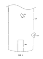
- FIG. 3 shows a camera arrangement according to one embodiment of the present disclosure.
- the wind turbine tower 104 typically includes a door 303 or similar access point that may permit access to stairs or ladders, which may provide access to the nacelle 102.
- the camera 301 is mounted at or in close proximity to the door 303.
- a camera 301 may be mounted in a location to monitor the area adjacent or in close proximity to access to door 303.
- Visual signals 203 provided to the central monitoring device 201 may be monitored, stored and/or analyzed to determine whether unauthorized personnel are attempting to gain access to the wind turbine 100 or are in close proximity to the wind turbine 100.
- cameras 301 may be mounted in locations to view the surrounding terrain to monitor terrain conditions and to detect unauthorized personnel.
- the visual signals 203 permit the central monitoring device 201 to determine whether maintenance is required.
- the visual signals 203 may indicate that unauthorized personnel, undesired terrain conditions or other undesired conditions surrounding the wind turbine 100 exists, and the central monitoring device 201 may take appropriate action.
- the central monitoring device 201 notifies local authorities or emergency services.
- the central monitoring device 201 dispatches maintenance personnel to service the wind turbine 100. Notifications and/or dispatching may be accomplished directly or indirectly by the central monitoring device 201 via a signal, notification or other indicia. "Maintenance" as utilized herein includes repair, restoring, replacing, removing or otherwise servicing wind turbine components or equipment.
- While not so limited maintenance may include removing spray paint, repairing damaged components, replacing stolen components or otherwise removing unauthorized personnel or unauthorized equipment from the wind turbine.
- the camera 301 may be any suitable type of camera 301 capable of converting images into visual signals.
- a still camera, a web camera or a video camera may be utilized to generate the visual signals.
- the camera 301 may be a still-camera or may take continuous images or video.
- the resolution or image density of the camera 301 may be any suitable resolution that provides ease of transmission, while permitting analysis to determine whether maintenance is required.
- the camera 301 may be an internet protocol (IP) camera. In this embodiment, the camera 301 uses IP address and sends information to a computer or other device in the central monitoring device 201.
- IP internet protocol
- the camera 301 may also include additional features, such as motion detection, lighting, actuation or other features known for use in providing image acquisition.
- a motion detector may be provided with the camera 301 to activate the camera 301 selectively, such as when unauthorized personnel pass in close proximity to the camera 301.
- the ability to selectively activate the camera 301 desirably permits reduced camera operation to reduce power requirements and to reduce the volume of undesired (e.g., wherein no action by the central monitoring device 201 is required) visual signals 203.
- a camera may be mounted on a rotational and/or linear actuator that can be locally or remotely controlled to obtain various desired views to reduce the number of cameras 301 required to monitor a plurality of components.
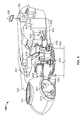
- a variable blade pitch drive 414 may control the pitch of blades 108 (not shown in FIG. 4 ) that drive hub 110 as a result of wind.
- the pitches of blades 108 are individually controlled by blade pitch drive 414.
- the drive train of the wind turbine 100 includes a main rotor shaft 416 connected to hub 110 via main bearing 430 and (in some configurations), at an opposite end of shaft 416 to a gear box 418.
- Gear box 418 in some configurations, utilizes a dual path geometry to drive an enclosed high speed shaft.
- the high speed shaft (not shown in FIG.
- ⁇ generator 4 is used to drive generator 420, which is mounted on main frame 432.
- rotor torque is transmitted via coupling 422.
- Yaw drive 424 and yaw deck 426 provide a yaw orientation system for wind turbine 100 to rotate the wind turbine to a position that faces the wind.
- Meterological boom 428 provides information for a turbine control system, including wind direction and/or wind speed.
- Cameras 301 may be mounted at various locations within or on the nacelle 102 to monitor equipment condition, status and/or operating conditions. For example, a camera 301 may be mounted to monitor the generator 420 and determine whether maintenance is required or if vandalism or burglary has occurred. In addition, if components are worn, if conditions are dangerous or outside acceptable operational parameters (i.e.
- the visual signals 203 provided to the central monitoring device 201 may determine that the wind turbine requires maintenance.
- the cameras 301 may be mounted to monitor components, such as the gear box 418, the pitch drive 414, the generator 420 or other components that may be damaged via operation, vandalism or burglary.
- An embodiment of the present disclosure includes a method for providing maintenance to a wind turbine.
- the method permits a central monitoring device 201 to obtain and analyze visual signals from one or more wind turbines.
- the visual signals 203 are generated from cameras 301 mounted in various locations on or within the wind turbine.
- the visual signals 203 are transmitted to the central monitoring device 201.
- the transmission may take place using any suitable transmission method including wired or wireless transmission.
- the visual signals are analyzed by the central monitoring device 201 to determine whether maintenance of the wind turbine is required.
- the analysis may be accomplished using any suitable technique including visual inspection, data analysis, color analysis, motion detection or any other technique that is capable of determining the presence of unauthorized personnel and/or whether wind turbine, components and/or equipment require maintenance.
- the analysis may result in dispatching emergency services to service the wind turbine if maintenance is determined to be required.
- the analysis may result in dispatching maintenance personnel to service the wind turbine if maintenance is determined to be required.
Landscapes
- Engineering & Computer Science (AREA)
- Life Sciences & Earth Sciences (AREA)
- Sustainable Development (AREA)
- Sustainable Energy (AREA)
- Chemical & Material Sciences (AREA)
- Combustion & Propulsion (AREA)
- Mechanical Engineering (AREA)
- General Engineering & Computer Science (AREA)
- Multimedia (AREA)
- Signal Processing (AREA)
- Wind Motors (AREA)
Abstract
A wind turbine monitoring system (200) having a central monitoring device 201 and one or more wind turbines. The central monitoring device (201) is capable of receiving signals (203) from one or more wind turbines (100). The wind turbines (100) each include one or more cameras (301) arranged and disposed to provide visual signals (203) transmittable to the central monitoring device (201). The visual signals (203) generated by the cameras (301) provide sufficient information to the central monitoring device (201) to determine whether maintenance to the wind turbine (100) is required.
Description
- The invention is directed generally to wind turbine monitoring and maintenance.
- Recently, wind turbines have received increased attention as environmentally safe and relatively inexpensive alternative energy sources. With this growing interest, considerable efforts have been made to develop wind turbines that are reliable and efficient.
- Generally, a wind turbine includes a rotor having multiple blades. The rotor is mounted to a housing or nacelle, which is positioned on top of a truss or tubular tower. Utility grade wind turbines (i.e., wind turbines designed to provide electrical power to a utility grid) can have large rotors (e.g., 30 or more meters in length). In addition, the wind turbines are typically mounted on towers that are at least 60 meters in height. Blades on these rotors transform wind energy into a rotational torque or force that drives one or more generators. As the blades are rotated by the wind, noise is inherently generated.
- Wind turbines may be installed in remote locations that are generally difficult to monitor or service on a regular basis. The cost of deploying personnel to the remote locations for service and maintenance is expensive and inefficient. In some locations, the wind turbine facilities are subject to vandalism or burglary. As wind turbines are damaged, such as by vandalism, additional maintenance is required increasing the operating costs of the wind turbine. At present, the wind turbine including the components of the wind turbine, such as the tower, and the electronic and structural components and equipment, includes no protection against vandalism and burglary.
- What is needed is a method and system for providing efficient maintenance and emergency response to wind turbine facilities. In addition, a method and system is needed for detecting burglary and/or vandalism and notifying wind turbine operators to permit efficient maintenance, such as repair of damage caused by the burglary or vandalism.
- One aspect of the present invention includes a wind turbine monitoring system having a central monitoring device and one or more wind turbines. The central monitoring device is capable of receiving signals from one or more wind turbines. The wind turbines each include one or more cameras arranged and disposed to provide visual signals transmittable to the central monitoring device. The visual signals generated by the cameras provide sufficient information to the central monitoring device to determine whether maintenance to the wind turbine is required.
- Another aspect of the present invention includes a method for providing maintenance to a wind turbine. The method includes providing a central monitoring device and one or more wind turbines. The central monitoring device is capable of receiving signals from the wind turbines. The wind turbines each include one or more cameras arranged and disposed to provide visual signals transmittable to the central monitoring device. The visual signals generated by the one or more cameras provide sufficient information to the central monitoring device to determine whether maintenance to the wind turbine is required. The visual signals are transmitted to the central monitoring device and are analyzed. A determination of whether maintenance is required is then made in response to the visual signals.
- An advantage of the present disclosure is that the monitoring system is capable of increasing safety at the wind turbine.
- Other features and advantages of the present invention will be apparent from the following more detailed description of the preferred embodiment, taken in conjunction with the accompanying drawings which illustrate, by way of example, the principles of the invention, and in which:
-
FIG. 1 shows a side elevational view of a wind turbine. -
FIG. 2 shows a wind turbine monitoring system according to an embodiment of the present disclosure. -
FIG. 3 shows a camera arrangement on the exterior of the wind turbine according to an embodiment of the present disclosure. -
FIG. 4 shows a cutaway view of a nacelle having a camera arrangement in the wind turbine according to an embodiment of the present invention. - Wherever possible, the same reference numbers will be used throughout the drawings to refer to the same or like parts.
- As shown in
FIG. 1 , awind turbine 100 generally comprises anacelle 102 housing a generator (not shown inFIG. 1 ). Nacelle 102 is a housing mounted atop atower 104, only a portion of which is shown inFIG. 1 . The height oftower 104 is selected based upon factors and conditions known in the art, and may extend to heights up to 60 meters or more. Thewind turbine 100 may be installed on any terrain providing access to areas having desirable wind conditions. The terrain may vary greatly and may include, but is not limited to, mountainous terrain or off-shore locations.Wind turbine 100 also comprises arotor 106 that includes one ormore rotor blades 108 attached to arotating hub 110. Althoughwind turbine 100 illustrated inFIG. 1 includes threerotor blades 108, there are no specific limits on the number ofrotor blades 108 required by various embodiments of the present invention. As theblades 108 rotate, noise is generated. - The
wind turbine 100 andtower 104 includes a large variety of equipment and components that are susceptible to vandalism and/or burglary, particularly inwind turbines 100 installed in more remote locations. Certain components are susceptible to theft, while others are subject to damage or destruction from access. In addition, exterior surfaces of thetower 104 may be damaged, requiring repair or servicing. - The present disclosure utilizes one or more cameras 301 (see e.g.,
FIGS. 3-4 ) to generate a visual signal 203 (see e.g.,FIG. 2 ) that can be analyzed to determine whether components are missing, damaged or otherwise require maintenance. In addition, if unauthorized personnel are detected, authorities or emergency services may be contacted and/or dispatched to thewind turbine 100 andtower 104. -
FIG. 2 shows a windturbine maintenance system 200 according to an embodiment of the present disclosure. Thesystem 200 includes acentral monitoring device 201 and a plurality ofwind turbines 100. The number ofwind turbines 100 in thesystem 200 is not limited and may include one or a large number ofwind turbines 100. A camera 301 (not shown inFIG. 2 ) is mounted on or within thewind turbine 100 andtower 104 and generates avisual signal 203. Thevisual signal 203 may be a digital, analog or other type of signal that provides an image, series of images or video that is viewable by thecentral monitoring device 201. Thevisual signal 203 is preferably includes images within the visible light, but may also include signals or images corresponding to other wavelengths or spectrums of light and may be varied and dependent upon the area or equipment being monitored. Thecentral monitoring device 201 may be a data acquisition device such as a microprocessor, a data storage device or other analysis tool. In another embodiment, thecentral monitoring device 201 may be personnel or a communication device usable by personnel. In another embodiment thecentral monitoring device 201 is the power control for a wind turbine farm or a utility operating the wind turbine farm. Thecentral monitoring device 201 may be autonomous or may be integrated within the wind farm control. Thevisual signals 203 may be transmitted to and/or from thewind turbine 100 andtower 104 in order to provide control or otherwise communicate with thewind turbine 100 in response to a condition requiring maintenance in response to the visual signals. In certain embodiments, equipment or other operational parameters. -
FIG. 3 shows a camera arrangement according to one embodiment of the present disclosure. Thewind turbine tower 104 typically includes adoor 303 or similar access point that may permit access to stairs or ladders, which may provide access to thenacelle 102. In one preferred embodiment, thecamera 301 is mounted at or in close proximity to thedoor 303. - A
camera 301 may be mounted in a location to monitor the area adjacent or in close proximity to access todoor 303.Visual signals 203 provided to thecentral monitoring device 201 may be monitored, stored and/or analyzed to determine whether unauthorized personnel are attempting to gain access to thewind turbine 100 or are in close proximity to thewind turbine 100. Inaddition cameras 301 may be mounted in locations to view the surrounding terrain to monitor terrain conditions and to detect unauthorized personnel. As discussed above, thevisual signals 203 permit thecentral monitoring device 201 to determine whether maintenance is required. For example, thevisual signals 203 may indicate that unauthorized personnel, undesired terrain conditions or other undesired conditions surrounding thewind turbine 100 exists, and thecentral monitoring device 201 may take appropriate action. In one embodiment, thecentral monitoring device 201 notifies local authorities or emergency services. In another embodiment, thecentral monitoring device 201 dispatches maintenance personnel to service thewind turbine 100. Notifications and/or dispatching may be accomplished directly or indirectly by thecentral monitoring device 201 via a signal, notification or other indicia. "Maintenance" as utilized herein includes repair, restoring, replacing, removing or otherwise servicing wind turbine components or equipment. - While not so limited maintenance may include removing spray paint, repairing damaged components, replacing stolen components or otherwise removing unauthorized personnel or unauthorized equipment from the wind turbine.
- The
camera 301 may be any suitable type ofcamera 301 capable of converting images into visual signals. In one embodiment, a still camera, a web camera or a video camera may be utilized to generate the visual signals. In addition, thecamera 301 may be a still-camera or may take continuous images or video. The resolution or image density of thecamera 301 may be any suitable resolution that provides ease of transmission, while permitting analysis to determine whether maintenance is required. In one embodiment, thecamera 301 may be an internet protocol (IP) camera. In this embodiment, thecamera 301 uses IP address and sends information to a computer or other device in thecentral monitoring device 201. - The
camera 301 may also include additional features, such as motion detection, lighting, actuation or other features known for use in providing image acquisition. For example, a motion detector may be provided with thecamera 301 to activate thecamera 301 selectively, such as when unauthorized personnel pass in close proximity to thecamera 301. The ability to selectively activate thecamera 301 desirably permits reduced camera operation to reduce power requirements and to reduce the volume of undesired (e.g., wherein no action by thecentral monitoring device 201 is required)visual signals 203. In addition, a camera may be mounted on a rotational and/or linear actuator that can be locally or remotely controlled to obtain various desired views to reduce the number ofcameras 301 required to monitor a plurality of components. - As shown in
FIG. 4 , various components are housed innacelle 102 atoptower 104 ofwind turbine 100. For example, a variableblade pitch drive 414 may control the pitch of blades 108 (not shown inFIG. 4 ) that drivehub 110 as a result of wind. In some configurations, the pitches ofblades 108 are individually controlled byblade pitch drive 414. The drive train of thewind turbine 100 includes amain rotor shaft 416 connected tohub 110 viamain bearing 430 and (in some configurations), at an opposite end ofshaft 416 to agear box 418.Gear box 418, in some configurations, utilizes a dual path geometry to drive an enclosed high speed shaft. The high speed shaft (not shown inFIG. 4 ) is used to drivegenerator 420, which is mounted onmain frame 432. In some configurations, rotor torque is transmitted viacoupling 422. Yaw drive 424 andyaw deck 426 provide a yaw orientation system forwind turbine 100 to rotate the wind turbine to a position that faces the wind. Meterological boom 428 provides information for a turbine control system, including wind direction and/or wind speed.Cameras 301 may be mounted at various locations within or on thenacelle 102 to monitor equipment condition, status and/or operating conditions. For example, acamera 301 may be mounted to monitor thegenerator 420 and determine whether maintenance is required or if vandalism or burglary has occurred. In addition, if components are worn, if conditions are dangerous or outside acceptable operational parameters (i.e. smoking, on fire, dislodged, discolored or otherwise damaged from operation), thevisual signals 203 provided to thecentral monitoring device 201 may determine that the wind turbine requires maintenance. In addition, thecameras 301 may be mounted to monitor components, such as thegear box 418, thepitch drive 414, thegenerator 420 or other components that may be damaged via operation, vandalism or burglary. - An embodiment of the present disclosure includes a method for providing maintenance to a wind turbine. The method permits a
central monitoring device 201 to obtain and analyze visual signals from one or more wind turbines. Thevisual signals 203 are generated fromcameras 301 mounted in various locations on or within the wind turbine. Thevisual signals 203 are transmitted to thecentral monitoring device 201. The transmission may take place using any suitable transmission method including wired or wireless transmission. The visual signals are analyzed by thecentral monitoring device 201 to determine whether maintenance of the wind turbine is required. The analysis may be accomplished using any suitable technique including visual inspection, data analysis, color analysis, motion detection or any other technique that is capable of determining the presence of unauthorized personnel and/or whether wind turbine, components and/or equipment require maintenance. The analysis may result in dispatching emergency services to service the wind turbine if maintenance is determined to be required. The analysis may result in dispatching maintenance personnel to service the wind turbine if maintenance is determined to be required. - While the invention has been described with reference to a preferred embodiment, it will be understood by those skilled in the art that various changes may be made and equivalents may be substituted for elements thereof without departing from the scope of the invention. In addition, many modifications may be made to adapt a particular situation or material to the teachings of the invention without departing from the essential scope thereof. Therefore, it is intended that the invention not be limited to the particular embodiment disclosed as the preferred mode contemplated for carrying out this invention, but that the invention will include all embodiments falling within the scope of the appended claims.
- Various aspects and embodiments of the present invention will now be defined in the following numbered clauses:
- 1. A wind turbine monitoring system comprising:
- a central monitoring device, the central monitoring device being capable of receiving signals from one or more wind turbines, the one or more wind turbines each comprising:
- one or more cameras arranged and disposed to provide visual signals transmittable to the central monitoring device;
wherein the visual signals generated by the one or more cameras provide sufficient information to the central monitoring device to determine whether maintenance to the wind turbine is required.
- one or more cameras arranged and disposed to provide visual signals transmittable to the central monitoring device;
- a central monitoring device, the central monitoring device being capable of receiving signals from one or more wind turbines, the one or more wind turbines each comprising:
- 2. The system of clause 1, wherein the visual signals include images wherein vandalism is visible.
- 3. The system of any preceding clause, wherein the visual signals include images of equipment wherein the conditions of the equipment is visible.
- 4. The system of any preceding clause, wherein the visual signals include images of surrounding terrain.
- 5. The system of any preceding clause, wherein the visual signals include images of wind turbine structures wherein the conditions of the wind turbine structures is visible.
- 6. The system of any preceding clause, wherein the visual signals are real-time images.
- 7. The system of any preceding clause, wherein the visual signals are stored images.
- 8. The system of any preceding clause, wherein the camera is a web camera.
- 9. The system of any preceding clause, wherein the camera is activated by a motion sensor.
- 10. A method for providing maintenance to a wind turbine comprising:
- providing a central monitoring device, the central monitoring device being capable of receiving signals from one or more wind turbines, the one or more wind turbines each comprising:
- one or more cameras arranged and disposed to provide visual signals transmittable to the central monitoring device;
wherein the visual signals generated by the one or more cameras provide sufficient information to the central monitoring device to determine whether maintenance to the wind turbine is required;
- one or more cameras arranged and disposed to provide visual signals transmittable to the central monitoring device;
- transmitting the visual signals to the central monitoring device;
- analyzing the visual signals; and
- determining whether maintenance of the wind turbine is required in response to the visual signals.
- providing a central monitoring device, the central monitoring device being capable of receiving signals from one or more wind turbines, the one or more wind turbines each comprising:
- 11. The method of clause 10, wherein the analyzing includes inspecting the images for unauthorized personnel.
- 12. The method of clause 10 or 11, further comprising dispatching emergency services to service the wind turbine if maintenance is determined to be required.
- 13.The method of any of clauses 10 to 12, wherein the analyzing includes inspecting wind turbine equipment for damage or vandalism.
- 14. The method of any of clauses 10 to 13, further comprising dispatching maintenance personnel to service the wind turbine if maintenance is determined to be required.
- 15. The method of any of clauses 10 to 14, further comprising replacing wind turbine components if maintenance is determined to be required.
- 16. The method of any of clauses 10 to 15, further comprising repairing wind turbine components if maintenance is determined to be required.
- 17. The method of any of clauses 10 to 16, wherein the visual signals are real-time images.
- 18. The method of any of clauses 10 to 17, wherein the visual signals are stored images.
- 19. The method of any of clauses 10 to 18, wherein the camera is a web camera.
- 20. The method of any of clauses 10 to 19, wherein the camera is activated by motion sensor.
Claims (9)
- A wind turbine monitoring system (200) comprising:a central monitoring device (201), the central monitoring device (201) being capable of receiving signals (203) from one or more wind turbines (100), the one or more wind turbines (100) each comprising:one or more cameras (301) arranged and disposed to provide visual signals (203) transmittable to the central monitoring device (201);
wherein the visual signals (203) generated by the one or more cameras (301) provide sufficient information to the central monitoring device (201) to determine whether maintenance to the wind turbine (100) is required. - The system of claim 1, wherein the visual signals (203) include images wherein vandalism is visible.
- The system of claim 1 or claim 2, wherein the visual signals (203) include images of equipment wherein the conditions of the equipment is visible.
- The system of any preceding claim, wherein the visual signals (203) include images of surrounding terrain.
- The system of any preceding claim, wherein the visual signals (203) include images of wind turbine structures wherein the conditions of the wind turbine structures is visible.
- The system of any preceding claim, wherein the visual signals (203) are real-time images.
- The system of any preceding claim, wherein the visual signals (203) are stored images.
- The system of any preceding claim, wherein the camera (301) is a web camera.
- The system of any preceding claim, wherein the camera (301) is activated by a motion sensor.
Applications Claiming Priority (1)
| Application Number | Priority Date | Filing Date | Title |
|---|---|---|---|
| US11/954,959 US20090153656A1 (en) | 2007-12-12 | 2007-12-12 | Wind turbine maintenance system |
Publications (1)
| Publication Number | Publication Date |
|---|---|
| EP2108834A2 true EP2108834A2 (en) | 2009-10-14 |
Family
ID=40752656
Family Applications (1)
| Application Number | Title | Priority Date | Filing Date |
|---|---|---|---|
| EP08170068A Withdrawn EP2108834A2 (en) | 2007-12-12 | 2008-11-27 | Wind turbine maintenance system |
Country Status (3)
| Country | Link |
|---|---|
| US (1) | US20090153656A1 (en) |
| EP (1) | EP2108834A2 (en) |
| CN (1) | CN101459830A (en) |
Families Citing this family (21)
| Publication number | Priority date | Publication date | Assignee | Title |
|---|---|---|---|---|
| CN102705162B (en) * | 2003-08-12 | 2014-10-22 | 纳博特斯克株式会社 | Yaw drive device for wind power generator |
| US20100103260A1 (en) * | 2008-10-27 | 2010-04-29 | Williams Scot I | Wind turbine inspection |
| US8275489B1 (en) * | 2009-04-21 | 2012-09-25 | Devine Timothy J | Systems and methods for deployment of wind turbines |
| US8577509B2 (en) * | 2009-06-24 | 2013-11-05 | Vestas Wind Systems A/S | Method and a system for controlling operation of a wind turbine |
| US8277183B2 (en) * | 2009-09-30 | 2012-10-02 | General Electric Company | Systems and methods for monitoring wind turbine operation |
| US20110135466A1 (en) * | 2010-01-14 | 2011-06-09 | General Electric Company | System and method for monitoring and controlling wind turbine blade deflection |
| US8771544B2 (en) * | 2010-05-10 | 2014-07-08 | Larry James Hopper | Stair tower module |
| CN102434403B (en) * | 2010-09-29 | 2015-09-09 | 通用电气公司 | For the system and method for wind turbine machine check |
| US8433425B2 (en) | 2011-04-29 | 2013-04-30 | General Electric Company | Method, system and computer program product for dynamic rule engine for a wind turbine farm |
| US20130050400A1 (en) * | 2011-08-31 | 2013-02-28 | Henrik Stiesdal | Arrangement and Method to Prevent a Collision of a Flying Animal with a Wind Turbine |
| DE102011082249A1 (en) * | 2011-09-07 | 2013-03-07 | Repower Systems Se | Method and system for de-icing a wind turbine |
| JP5619798B2 (en) * | 2012-02-24 | 2014-11-05 | 三菱重工業株式会社 | Wear management device, wear management method, wind power generator equipped with the same, and wind turbine blade monitoring system |
| US20130309088A1 (en) * | 2012-05-15 | 2013-11-21 | Clipper Windpower, Llc | Method for Protecting Wind Turbine Equipment in Fire Event |
| CA2875266C (en) | 2012-06-18 | 2022-01-11 | Collineo Inc. | Remote visual inspection system and method |
| JP2016017423A (en) * | 2014-07-07 | 2016-02-01 | 株式会社日立製作所 | Wind turbine monitoring system |
| DE102015007649A1 (en) * | 2015-06-17 | 2016-12-22 | Senvion Gmbh | Method and system for monitoring wind turbines of a wind farm |
| US12180931B2 (en) | 2019-10-11 | 2024-12-31 | The Aes Corporation | System and method for determining an operating condition of a wind turbine |
| EP3879359A1 (en) * | 2020-03-11 | 2021-09-15 | Siemens Gamesa Renewable Energy A/S | A method for computer-implemented identifying an unauthorized access to a wind farm |
| CN112258769A (en) * | 2020-11-09 | 2021-01-22 | 华能通辽风力发电有限公司 | Automatic identification and management control system for dangerous source points of fan |
| EP4281666B1 (en) | 2021-01-20 | 2025-05-14 | Vestas Wind Systems A/S | Controlling operation in different zones of a wind turbine |
| SE2330460A1 (en) * | 2023-10-15 | 2025-03-18 | Elevated Launch AB | A wind power plant configured to enable an electronic warfare system to be mounted to said wind power plant |
Family Cites Families (7)
| Publication number | Priority date | Publication date | Assignee | Title |
|---|---|---|---|---|
| KR100337601B1 (en) * | 1999-09-27 | 2002-05-22 | 윤종용 | The semiconductor integrated circuit having internal state monitoring circuit and a method for monitoring internal state using the same |
| DE19948194C2 (en) * | 1999-10-06 | 2001-11-08 | Aloys Wobben | Process for monitoring wind turbines |
| AU2003258492A1 (en) * | 2002-09-04 | 2004-03-29 | Pp Energy Aps | A method and a device for lifting and/or lowering of objects at a wind turbine or the like and uses hereof |
| US7217091B2 (en) * | 2004-07-20 | 2007-05-15 | General Electric Company | Methods and apparatus for deicing airfoils or rotor blades |
| US7688544B1 (en) * | 2005-05-23 | 2010-03-30 | Seagate Technology Llc | Magnetic heads disk drives and methods with floating pole tip or shunted pole tip for reduced pole tip erasure |
| DE102006034251B8 (en) * | 2006-07-21 | 2014-08-21 | Senvion Se | Method for operating a wind energy plant |
| US20090110539A1 (en) * | 2007-10-30 | 2009-04-30 | Ulrich Uphues | Wind farm and method for controlling same |
-
2007
- 2007-12-12 US US11/954,959 patent/US20090153656A1/en not_active Abandoned
-
2008
- 2008-11-27 EP EP08170068A patent/EP2108834A2/en not_active Withdrawn
- 2008-12-11 CN CNA200810187163XA patent/CN101459830A/en active Pending
Also Published As
| Publication number | Publication date |
|---|---|
| CN101459830A (en) | 2009-06-17 |
| US20090153656A1 (en) | 2009-06-18 |
Similar Documents
| Publication | Publication Date | Title |
|---|---|---|
| EP2108834A2 (en) | Wind turbine maintenance system | |
| KR100954090B1 (en) | Health and usage monitoring system for wind turbine | |
| US8764393B2 (en) | Method for the operation of a wind power plant | |
| CN101490411B (en) | Method for operating a wind energy installation | |
| US8757003B1 (en) | Multi-frequency-band blade condition monitoring system | |
| DK177922B1 (en) | Method and system for monitoring wind turbine | |
| US8511177B1 (en) | Blade condition monitoring system | |
| EP2889472B1 (en) | Wind farm, control method thereof and wind power generation unit | |
| US20110316278A1 (en) | Locking Device for the Rotor of Wind Turbines | |
| EP2075465B1 (en) | Individual blade noise measurement system and method for wind turbines | |
| EP2440781B1 (en) | A wind power plant and a method of operating a wind power plant | |
| EP3163071A1 (en) | Automatic tightening of bolts | |
| US20190048851A1 (en) | Method for controlling a wind turbine with access hatch interlocks, and associated wind turbine | |
| DK2343453T3 (en) | A method of operating a wind power installation | |
| CN116816613A (en) | Wind generating set blade form monitoring system | |
| JP7621920B2 (en) | Wind turbine monitoring device, method, and program | |
| CN119042087B (en) | Safety early warning protection system for offshore wind power equipment and use method | |
| CN110905736A (en) | A fan operation monitoring system | |
| KR20210033202A (en) | A system for forecasting of break of industrial machinery/equipment | |
| Giebel et al. | CleverFarm-A SuperSCADA system for wind farms | |
| CN118148831A (en) | Remote monitoring system and method for wind power generation | |
| KR101400150B1 (en) | Rotor lock control system and method of wind turbine | |
| JP2008025993A (en) | Lightning detection device for blade | |
| JP7421828B1 (en) | Wind power generator monitoring system, wind power generation equipment, and wind power generator monitoring method | |
| US12012927B2 (en) | System and method for detecting a failure condition in a component of a wind turbine |
Legal Events
| Date | Code | Title | Description |
|---|---|---|---|
| PUAI | Public reference made under article 153(3) epc to a published international application that has entered the european phase |
Free format text: ORIGINAL CODE: 0009012 |
|
| AK | Designated contracting states |
Kind code of ref document: A2 Designated state(s): AT BE BG CH CY CZ DE DK EE ES FI FR GB GR HR HU IE IS IT LI LT LU LV MC MT NL NO PL PT RO SE SI SK TR |
|
| AX | Request for extension of the european patent |
Extension state: AL BA MK RS |
|
| STAA | Information on the status of an ep patent application or granted ep patent |
Free format text: STATUS: THE APPLICATION IS DEEMED TO BE WITHDRAWN |
|
| 18D | Application deemed to be withdrawn |
Effective date: 20130601 |