EP2108730A1 - Washer/dryer and relevant operating cycle - Google Patents
Washer/dryer and relevant operating cycle Download PDFInfo
- Publication number
- EP2108730A1 EP2108730A1 EP08425240A EP08425240A EP2108730A1 EP 2108730 A1 EP2108730 A1 EP 2108730A1 EP 08425240 A EP08425240 A EP 08425240A EP 08425240 A EP08425240 A EP 08425240A EP 2108730 A1 EP2108730 A1 EP 2108730A1
- Authority
- EP
- European Patent Office
- Prior art keywords
- temperature
- condensing
- resistor
- sensor
- turning
- Prior art date
- Legal status (The legal status is an assumption and is not a legal conclusion. Google has not performed a legal analysis and makes no representation as to the accuracy of the status listed.)
- Granted
Links
Images


Classifications
-
- D—TEXTILES; PAPER
- D06—TREATMENT OF TEXTILES OR THE LIKE; LAUNDERING; FLEXIBLE MATERIALS NOT OTHERWISE PROVIDED FOR
- D06F—LAUNDERING, DRYING, IRONING, PRESSING OR FOLDING TEXTILE ARTICLES
- D06F34/00—Details of control systems for washing machines, washer-dryers or laundry dryers
- D06F34/08—Control circuits or arrangements thereof
-
- D—TEXTILES; PAPER
- D06—TREATMENT OF TEXTILES OR THE LIKE; LAUNDERING; FLEXIBLE MATERIALS NOT OTHERWISE PROVIDED FOR
- D06F—LAUNDERING, DRYING, IRONING, PRESSING OR FOLDING TEXTILE ARTICLES
- D06F33/00—Control of operations performed in washing machines or washer-dryers
- D06F33/30—Control of washing machines characterised by the purpose or target of the control
- D06F33/32—Control of operational steps, e.g. optimisation or improvement of operational steps depending on the condition of the laundry
-
- D—TEXTILES; PAPER
- D06—TREATMENT OF TEXTILES OR THE LIKE; LAUNDERING; FLEXIBLE MATERIALS NOT OTHERWISE PROVIDED FOR
- D06F—LAUNDERING, DRYING, IRONING, PRESSING OR FOLDING TEXTILE ARTICLES
- D06F2103/00—Parameters monitored or detected for the control of domestic laundry washing machines, washer-dryers or laundry dryers
- D06F2103/28—Air properties
- D06F2103/32—Temperature
-
- D—TEXTILES; PAPER
- D06—TREATMENT OF TEXTILES OR THE LIKE; LAUNDERING; FLEXIBLE MATERIALS NOT OTHERWISE PROVIDED FOR
- D06F—LAUNDERING, DRYING, IRONING, PRESSING OR FOLDING TEXTILE ARTICLES
- D06F2105/00—Systems or parameters controlled or affected by the control systems of washing machines, washer-dryers or laundry dryers
- D06F2105/28—Electric heating
Definitions
- the present invention relates to washers/dryers, and in particular to a washer/dryer in which the drying system includes a feedback loop that allows an operation suitable to optimize time and consumptions of the laundry drying phase at the end of the washing cycle.
- a fan creates an air stream in the circuit and a resistor heats the air circulating in said circuit.
- an electrovalve is opened to admit condensing water into a condensing duct, where the condensing water is kept in suspension by the suction created by the fan.
- the fan receives partially cooled and dried air that is heated again by the resistor and returned to the tank.
- the air heating resistor is turned off during the last minutes of the drying cycle, whereas the fan keeps on working so as to perform a laundry cooling step otherwise the laundry would be too hot for the user to remove it safely from the drum.
- the object of the present invention is to provide a washer/dryer which overcomes said drawbacks, and a relevant operating cycle.
- This object is achieved by means of a washer/dryer including at least three temperature sensors to detect the air temperature respectively in the tank, at the outlet of the condensing unit and downstream from the heating resistor.
- Other advantageous features of the present washer/dryer are disclosed in the dependent claims.
- the main advantage of this washer/dryer is that of carrying out the drying cycle while maintaining the optimum temperature conditions at the various points in the circuit, so as to increase the condensing effectiveness and decrease the drying time, with a subsequently lower consumption of power and condensing fluid.
- a second important advantage of the present machine is that of optimizing the consumption of power and condensing fluid by adapting it to the extent of the laundry load to be dried.
- Another significant advantage of this arrangement comes from its structural simplicity that allows to achieve the above-mentioned improvement in effectiveness without affecting the overall size of the machine and with only a minimum increase in manufacturing cost.
- the drying circuit conventionally includes a centrifugal fan F connected to a condensing duct C where the stream of moist air, coming from the tank through an air entrance AE, flows in a direction opposite to the condensing water CW introduced in duct C through a relevant water entrance WE.
- the moisture condensed in duct C is conveyed to the drain pump through a bottom drain D.
- a resistor R with a relevant safety thermostat T, is arranged downstream from fan F in a return duct H to heat air prior to returning it to the tank.
- the air temperature downstream from fan F is detected by a temperature sensor S3, in order to prevent the introduction into the tank of excessively hot air.
- the novel aspect of the present invention is the presence of other two temperature sensors, namely a sensor S1 (not shown) detecting the air temperature in the tank and a sensor S2 arranged at the top of the condensing duct C, i.e. at the outlet of the condensing unit prior to the entrance of the air into fan F. Thanks to these two sensors S1, S2 it is possible to achieve a feedback loop that controls the operation of the condensing unit, as it will be explained hereunder with reference to Figs.2-4 .
- the first time/temperature chart illustrated in Fig.2 shows the course of temperatures TS1 and TS2, i.e. the temperatures detected by sensors S1 and S2 respectively, and indicates three temperature thresholds Z0, W and Z1 at which different steps of the drying cycle take place. There is also indicated a time tr at which there is performed a preliminary "sensor reset" step required to take into account the inevitable manufacturing tolerances of the sensors.
- the "sensor reset" step implies that, called ⁇ T the difference detected at time tr, the values of TS1 and TS2 will be corrected by ⁇ ⁇ T/2 or one of the two values will be used as a reference and the other one will be corrected by ⁇ ⁇ T, the sign of the correction depending on which sensor detects the higher temperature at time tr and/or is used as a reference.
- said "sensor reset" step could be performed even only once, as long as one of the two sensors S1 or S2 is not replaced, since the detected difference depends on the manufacturing tolerances. However, since the sensors may get dirty or deteriorate during the machine life, without having to be replaced for this reason, in order to guarantee a correct operation of the machine it is preferable to perform this step at each operating cycle or at least periodically.
- the second time/temperature chart illustrated in Fig.3 shows the course of temperatures TS3 detected by sensor S3 in the duct that introduces the air heated by resistor R into the tank. Furthermore, there are indicated the two temperature thresholds U3 and V3 representing respectively the maximum temperature at which resistor R is turned off and the minimum temperature at which the latter is turned back on.
- the hot air introduced in the tank increases temperature TS1 detected by sensor S1, which controls the performing of a centrifugation that lasts a few minutes upon reaching the first threshold Z0.
- said centrifugation is present also in the conventional drying cycle, but it is carried out at a fixed moment in the cycle regardless of the laundry conditions. On the contrary, in the present machine this step is performed at the precise time when the tank reaches a preset temperature Z0, detected by S1, of maximum yield for extracting the residual moisture from the laundry.
- the feedback provided by sensor S1 therefore allows to control the time of centrifugation in order to achieve the maximum power and performance yield.
- the step following the centrifugation is that of turning on the condensing unit, i.e. admitting the condensing water CW into duct C through entrance WE in the case of the embodiment illustrated in Fig.1 .
- Said turning on takes place only when sensor S1 detects that temperature TS1 in the tank has reached a second threshold Z1.
- the time of turning off the condensing unit is determined by sensor S2 that detects when temperature TS2 decreases below the temperature threshold W, in order to prevent an excessive decrease in temperature of the air reaching resistor R.
- the feedback provided by the pair of sensors S1, S2 allows to optimize both the consumption of condensing fluid in duct C and the power consumption by resistor R.
- the "sensor reset" step not only allows to use as temperature sensors even inexpensive components such as NTC thermistors rather than other more expensive types of sensors, but it also serves to prevent machine malfunctionings in case of "converging" manufacturing tolerances of sensors S1 and S2.
- the temperature thresholds W and Z1 are very close it could happen that with a sensor S1 erring by excess and a sensor S2 erring by defect the operation of the condensing unit is immediately stopped because the tolerance ranges of sensors S1, S2 overlap.
- steps f)-h) depends on the value of thresholds W, U3, V3 since the operating periods of the condensing unit and resistor R depend respectively on the sensor pair S1, S2 and on sensor S3 that operate independently of each other.
Landscapes
- Engineering & Computer Science (AREA)
- Textile Engineering (AREA)
- Control Of Washing Machine And Dryer (AREA)
- Detail Structures Of Washing Machines And Dryers (AREA)
- Meat, Egg Or Seafood Products (AREA)
- Medicines Containing Material From Animals Or Micro-Organisms (AREA)
- Beans For Foods Or Fodder (AREA)
Abstract
Description
- The present invention relates to washers/dryers, and in particular to a washer/dryer in which the drying system includes a feedback loop that allows an operation suitable to optimize time and consumptions of the laundry drying phase at the end of the washing cycle.
- It is known that in washing machines that also perform the drying of the washed laundry there is provided a circuit to circulate air between the laundry-containing drum and a condensing unit, in which the moisture removed from the laundry is condensed and discharged by means of the drain pump of the machine. Specific reference will be made hereafter to a condensing unit that consists of a simple condensing duct into which water is admitted through an electrovalve, but it is clear that what is being said applies to a washer/dryer provided with a condensing unit of any kind that can even use a condensing fluid different from water.
- During the drying step a fan creates an air stream in the circuit and a resistor heats the air circulating in said circuit. After this initial phase, an electrovalve is opened to admit condensing water into a condensing duct, where the condensing water is kept in suspension by the suction created by the fan.
- In this way, the vapor sucked in from the tank encounters the suspended water and partially condenses toward the drain pump through a suitable drain pipe. Therefore, the fan receives partially cooled and dried air that is heated again by the resistor and returned to the tank. The air heating resistor is turned off during the last minutes of the drying cycle, whereas the fan keeps on working so as to perform a laundry cooling step otherwise the laundry would be too hot for the user to remove it safely from the drum.
- The most serious drawback of this known arrangement is that the fluid used to condense the moisture is continuously introduced into the condensing unit during the whole drying step without any feedback control. In this way it is not possible to maintain the optimum drying conditions, that are found only within a specific temperature range.
- In fact since the process of condensing the moisture removed from the laundry is not monitored and controlled as far as temperature is concerned, using too much condensing fluid results in cooling down too much the system that has then to be taken back to the correct temperature with a waste of energy, whereas using too little condensing fluid results in condensing little moisture and therefore extending the drying time.
- This results in a poor condensing effectiveness and/or a long drying time, with a subsequently high power consumption due to the long operating period of the fan and resistor and possibly even a waste of condensing fluid.
- Therefore the object of the present invention is to provide a washer/dryer which overcomes said drawbacks, and a relevant operating cycle. This object is achieved by means of a washer/dryer including at least three temperature sensors to detect the air temperature respectively in the tank, at the outlet of the condensing unit and downstream from the heating resistor. Other advantageous features of the present washer/dryer are disclosed in the dependent claims.
- The main advantage of this washer/dryer is that of carrying out the drying cycle while maintaining the optimum temperature conditions at the various points in the circuit, so as to increase the condensing effectiveness and decrease the drying time, with a subsequently lower consumption of power and condensing fluid.
- A second important advantage of the present machine is that of optimizing the consumption of power and condensing fluid by adapting it to the extent of the laundry load to be dried.
- Another significant advantage of this arrangement comes from its structural simplicity that allows to achieve the above-mentioned improvement in effectiveness without affecting the overall size of the machine and with only a minimum increase in manufacturing cost.
- These and other advantages and characteristics of the washer/dryer according to the present invention will be clear to those skilled in the art from the following detailed description of an embodiment thereof, with reference to the annexed drawings wherein:
-
Fig.1 is a front perspective view showing the drying circuit, where the wash tank is omitted for the sake of clarity; -
Fig.2 is a time/temperature chart showing the course of the air temperature in the tank and at the outlet of the condensing unit; -
Fig.3 is a time/temperature chart showing the course of the air temperature downstream from the resistor; and -
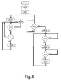
Fig.4 is a flow chart showing the feedback operation of the drying system. - Referring to
Fig.1 , there is seen that in a washer/dryer according to the present invention the drying circuit conventionally includes a centrifugal fan F connected to a condensing duct C where the stream of moist air, coming from the tank through an air entrance AE, flows in a direction opposite to the condensing water CW introduced in duct C through a relevant water entrance WE. The moisture condensed in duct C is conveyed to the drain pump through a bottom drain D. - A resistor R, with a relevant safety thermostat T, is arranged downstream from fan F in a return duct H to heat air prior to returning it to the tank. The air temperature downstream from fan F is detected by a temperature sensor S3, in order to prevent the introduction into the tank of excessively hot air.
- The novel aspect of the present invention is the presence of other two temperature sensors, namely a sensor S1 (not shown) detecting the air temperature in the tank and a sensor S2 arranged at the top of the condensing duct C, i.e. at the outlet of the condensing unit prior to the entrance of the air into fan F. Thanks to these two sensors S1, S2 it is possible to achieve a feedback loop that controls the operation of the condensing unit, as it will be explained hereunder with reference to
Figs.2-4 . - The first time/temperature chart illustrated in
Fig.2 shows the course of temperatures TS1 and TS2, i.e. the temperatures detected by sensors S1 and S2 respectively, and indicates three temperature thresholds Z0, W and Z1 at which different steps of the drying cycle take place. There is also indicated a time tr at which there is performed a preliminary "sensor reset" step required to take into account the inevitable manufacturing tolerances of the sensors. - In fact since sensors S1 and S2 at the beginning of the cycle, or in any case prior to turning on the condensing unit, should detect the same temperature, at time tr the difference between the temperatures detected by the two sensors is read and stored by the control unit, that will then use it as a correction factor for the temperatures detected during the condensing step.
- In other words, the "sensor reset" step implies that, called ΔT the difference detected at time tr, the values of TS1 and TS2 will be corrected by ± ΔT/2 or one of the two values will be used as a reference and the other one will be corrected by ± ΔT, the sign of the correction depending on which sensor detects the higher temperature at time tr and/or is used as a reference.
- It should be noted that said "sensor reset" step could be performed even only once, as long as one of the two sensors S1 or S2 is not replaced, since the detected difference depends on the manufacturing tolerances. However, since the sensors may get dirty or deteriorate during the machine life, without having to be replaced for this reason, in order to guarantee a correct operation of the machine it is preferable to perform this step at each operating cycle or at least periodically.
- The second time/temperature chart illustrated in
Fig.3 shows the course of temperatures TS3 detected by sensor S3 in the duct that introduces the air heated by resistor R into the tank. Furthermore, there are indicated the two temperature thresholds U3 and V3 representing respectively the maximum temperature at which resistor R is turned off and the minimum temperature at which the latter is turned back on. - With reference now also to the flow chart illustrated in
Fig.4 , there is described the simple and effective operation of the washer/dryer according to the present invention. - At the start of the operating cycle there is first turned on fan F to create an air stream, and then the "sensor reset" step is performed at time tr as explained above. Whereafter, resistor R is turned on for a period of operation defined by sensor S3 that achieves a feedback loop such that temperature TS3 remains within the U3-V3 range as previously mentioned.
- The hot air introduced in the tank increases temperature TS1 detected by sensor S1, which controls the performing of a centrifugation that lasts a few minutes upon reaching the first threshold Z0. It should be noted that said centrifugation is present also in the conventional drying cycle, but it is carried out at a fixed moment in the cycle regardless of the laundry conditions. On the contrary, in the present machine this step is performed at the precise time when the tank reaches a preset temperature Z0, detected by S1, of maximum yield for extracting the residual moisture from the laundry. The feedback provided by sensor S1 therefore allows to control the time of centrifugation in order to achieve the maximum power and performance yield.
- The step following the centrifugation is that of turning on the condensing unit, i.e. admitting the condensing water CW into duct C through entrance WE in the case of the embodiment illustrated in
Fig.1 . Said turning on takes place only when sensor S1 detects that temperature TS1 in the tank has reached a second threshold Z1. - Subsequently, the time of turning off the condensing unit is determined by sensor S2 that detects when temperature TS2 decreases below the temperature threshold W, in order to prevent an excessive decrease in temperature of the air reaching resistor R. In this way, the feedback provided by the pair of sensors S1, S2 allows to optimize both the consumption of condensing fluid in duct C and the power consumption by resistor R.
- The iterative operation of the resistor and condensing unit continues as illustrated in
Fig.4 until the drying system determines that the laundry is dry, through a moisture sensor and/or according to the operating time. Whereafter, fan F continues to operate for some minutes to perform the final laundry cooling step and finally the drying cycle ends (these last cycle steps are omitted inFig.4 ). - It should be noted that the "sensor reset" step not only allows to use as temperature sensors even inexpensive components such as NTC thermistors rather than other more expensive types of sensors, but it also serves to prevent machine malfunctionings in case of "converging" manufacturing tolerances of sensors S1 and S2. In fact, since the temperature thresholds W and Z1 are very close it could happen that with a sensor S1 erring by excess and a sensor S2 erring by defect the operation of the condensing unit is immediately stopped because the tolerance ranges of sensors S1, S2 overlap.
- The operating cycle of the washer/dryer according to the present invention can therefore be summarized in the following steps:
- a) turning on fan F;
- b) "resetting" the temperature sensors S1, S2;
- c) turning on resistor R;
- d) performing a centrifugation when temperature TS1 detected by sensor S1 reaches a first temperature threshold Z0;
- e) turning on the condensing unit when temperature TS1 reaches a second temperature threshold Z1;
- f) turning off the condensing unit when temperature TS2 detected by sensor S2 reaches a third temperature threshold W;
- g) iterating steps e) and f);
- h) turning off and turning back on resistor R so as to maintain the temperature TS3 detected by sensor S3 within a range U3-V3;
- i) iterating steps g) and h) until the laundry is deemed dry;
- j) turning off resistor R and the condensing unit;
- k) turning off fan F after a period of air circulation suitable to cool the laundry.
- It should be noted that the exact sequence of steps f)-h) depends on the value of thresholds W, U3, V3 since the operating periods of the condensing unit and resistor R depend respectively on the sensor pair S1, S2 and on sensor S3 that operate independently of each other.
- It is clear that the above-described and illustrated embodiment of the washer/dryer according to the invention is just an example susceptible of various modifications. In particular, the exact type and arrangement of the temperature sensors can change according to specific manufacturing needs, and the "sensor reset" step can take place even before turning on the fan or after the centrifugation as long as it is set prior to turning on the condensing unit.
Claims (8)
- Washer/dryer having a drying circuit in which air circulates between a wash tank and a condensing unit under the action of a fan (F), is heated by a resistor (R) and the air temperature downstream from said resistor (R) is detected by at least a first temperature sensor (S3) prior to introducing it into said tank, characterized in that it includes at least a second temperature sensor (S1) suitable to detect the air temperature in the tank and a third temperature sensor (S2) suitable to detect the air temperature at the outlet of said condensing unit, all three temperature sensors (S1, S2, S3) being operatively connected to a control unit that controls the operation of the resistor (R) and of the condensing unit.
- Washer/dryer according to claim 1, characterized in that one or more temperature sensors (S1, S2, S3) are NTC thermistors.
- Washer/dryer according to claim 1 or 2, characterized in that it further includes a laundry moisture sensor.
- Washer/dryer according to one of the preceding claims, characterized in that the condensing unit comprises a condensing duct (C) where the stream of moist air coming from the tank through an air entrance (AE) flows in the opposite direction with respect to condensing water (CW) introduced into said condensing duct (C) through a relevant water entrance (WE), the moisture condensed in the duct (C) being conveyed to a drain pump through a bottom drain (D).
- Operating cycle for a washer/dryer according to one of the preceding claims, characterized in that it includes the following steps:a) turning on the fan (F);b) "resetting" the second (S1) and third (S2) temperature sensors;c) turning on the resistor (R);d) performing a centrifugation when the temperature (TS1) detected by the second sensor (S1) reaches a first threshold (Z0);e) turning on the condensing unit when said temperature (TS1) reaches a second threshold (Z1);f) turning off the condensing unit when the temperature (TS2) detected by the third sensor (S2) reaches a third threshold (W);g) iterating steps e) and f);h) turning off and turning back on the resistor (R) so as to maintain the temperature (TS3) detected by the first sensor (S3) within a preset range (U3-V3);i) iterating steps g) and h) until the laundry is deemed dry;j) turning off the resistor (R) and stopping the introduction of condensing fluid in the condensing duct (C);k) turning off the fan (F) after a period of air circulation suitable to cool the laundry.
- Operating cycle according to claim 5, characterized in that in step i) the laundry is deemed dry according to the moisture level detected by a suitable sensor.
- Operating cycle according to claim 5 or 6, characterized in that step b) can be performed at any time prior to step e).
- Operating cycle according to one of claims 5 to 7, characterized in that step b) can be performed only on the occasion of the first cycle or only periodically.
Priority Applications (5)
| Application Number | Priority Date | Filing Date | Title |
|---|---|---|---|
| AT08425240T ATE475740T1 (en) | 2008-04-10 | 2008-04-10 | WASHING/DRYING DEVICE AND APPROPRIATE OPERATING CYCLE |
| PL08425240T PL2108730T3 (en) | 2008-04-10 | 2008-04-10 | Washer/dryer and relevant operating cycle |
| DE602008001966T DE602008001966D1 (en) | 2008-04-10 | 2008-04-10 | Washing / drying device and corresponding operating cycle |
| ES08425240T ES2348351T3 (en) | 2008-04-10 | 2008-04-10 | WASHER / DRYER AND CORRESPONDING OPERATING CYCLE. |
| EP08425240A EP2108730B1 (en) | 2008-04-10 | 2008-04-10 | Washer/dryer and relevant operating cycle |
Applications Claiming Priority (1)
| Application Number | Priority Date | Filing Date | Title |
|---|---|---|---|
| EP08425240A EP2108730B1 (en) | 2008-04-10 | 2008-04-10 | Washer/dryer and relevant operating cycle |
Publications (2)
| Publication Number | Publication Date |
|---|---|
| EP2108730A1 true EP2108730A1 (en) | 2009-10-14 |
| EP2108730B1 EP2108730B1 (en) | 2010-07-28 |
Family
ID=39739787
Family Applications (1)
| Application Number | Title | Priority Date | Filing Date |
|---|---|---|---|
| EP08425240A Active EP2108730B1 (en) | 2008-04-10 | 2008-04-10 | Washer/dryer and relevant operating cycle |
Country Status (5)
| Country | Link |
|---|---|
| EP (1) | EP2108730B1 (en) |
| AT (1) | ATE475740T1 (en) |
| DE (1) | DE602008001966D1 (en) |
| ES (1) | ES2348351T3 (en) |
| PL (1) | PL2108730T3 (en) |
Cited By (4)
| Publication number | Priority date | Publication date | Assignee | Title |
|---|---|---|---|---|
| EP2570548A1 (en) * | 2011-09-19 | 2013-03-20 | Electrolux Home Products Corporation N.V. | A washer-dryer with at least one condenser |
| EP2554740A3 (en) * | 2011-08-01 | 2013-07-31 | Samsung Electronics Co., Ltd. | Drying apparatus and washing machine having the same and control method thereof |
| US9080283B2 (en) | 2011-10-06 | 2015-07-14 | Whirlpool Corporation | Method to control a drying cycle of a laundry treating appliance |
| CN114775216A (en) * | 2022-04-29 | 2022-07-22 | 珠海格力电器股份有限公司 | Clothes treatment device and method and washing and drying machine |
Families Citing this family (1)
| Publication number | Priority date | Publication date | Assignee | Title |
|---|---|---|---|---|
| CN113417123A (en) * | 2021-07-23 | 2021-09-21 | 珠海格力电器股份有限公司 | Clothes drying control method, clothes dryer and storage medium |
Citations (2)
| Publication number | Priority date | Publication date | Assignee | Title |
|---|---|---|---|---|
| EP1666655A2 (en) * | 2004-12-02 | 2006-06-07 | Samsung Electronics Co., Ltd. | Eliminating wrinkles in laundry |
| EP1852533A1 (en) * | 2006-05-02 | 2007-11-07 | Electrolux Home Products Corporation N.V. | Steam supplying method and treatment apparatus |
-
2008
- 2008-04-10 AT AT08425240T patent/ATE475740T1/en not_active IP Right Cessation
- 2008-04-10 DE DE602008001966T patent/DE602008001966D1/en active Active
- 2008-04-10 PL PL08425240T patent/PL2108730T3/en unknown
- 2008-04-10 ES ES08425240T patent/ES2348351T3/en active Active
- 2008-04-10 EP EP08425240A patent/EP2108730B1/en active Active
Patent Citations (2)
| Publication number | Priority date | Publication date | Assignee | Title |
|---|---|---|---|---|
| EP1666655A2 (en) * | 2004-12-02 | 2006-06-07 | Samsung Electronics Co., Ltd. | Eliminating wrinkles in laundry |
| EP1852533A1 (en) * | 2006-05-02 | 2007-11-07 | Electrolux Home Products Corporation N.V. | Steam supplying method and treatment apparatus |
Cited By (6)
| Publication number | Priority date | Publication date | Assignee | Title |
|---|---|---|---|---|
| EP2554740A3 (en) * | 2011-08-01 | 2013-07-31 | Samsung Electronics Co., Ltd. | Drying apparatus and washing machine having the same and control method thereof |
| US9657432B2 (en) | 2011-08-01 | 2017-05-23 | Samsung Electronics Co., Ltd. | Drying apparatus and washing machine having the same and control method thereof |
| EP2570548A1 (en) * | 2011-09-19 | 2013-03-20 | Electrolux Home Products Corporation N.V. | A washer-dryer with at least one condenser |
| US10407818B2 (en) | 2011-09-19 | 2019-09-10 | Electrolux Home Products Corporation N.V. | Washer-dryer with at least one condenser |
| US9080283B2 (en) | 2011-10-06 | 2015-07-14 | Whirlpool Corporation | Method to control a drying cycle of a laundry treating appliance |
| CN114775216A (en) * | 2022-04-29 | 2022-07-22 | 珠海格力电器股份有限公司 | Clothes treatment device and method and washing and drying machine |
Also Published As
| Publication number | Publication date |
|---|---|
| ES2348351T3 (en) | 2010-12-03 |
| DE602008001966D1 (en) | 2010-09-09 |
| ATE475740T1 (en) | 2010-08-15 |
| EP2108730B1 (en) | 2010-07-28 |
| PL2108730T3 (en) | 2010-12-31 |
Similar Documents
| Publication | Publication Date | Title |
|---|---|---|
| EP2920356B1 (en) | Method of operating a heat pump laundry dryer and heat pump laundry dryer or heat pump washing machine having drying function | |
| EP2390404B1 (en) | Laundry treatment apparatus having heat pump system | |
| EP2935687B1 (en) | A method for controlling a laundry drying machine and a corresponding laundry drying machine | |
| EP2108730B1 (en) | Washer/dryer and relevant operating cycle | |
| EP3124680B1 (en) | Method for adapting operation parameters during drying in a heat pump dryer | |
| EP1852534B1 (en) | Washer/dryer with additional condensing circuit | |
| US9109320B2 (en) | Method for sterilizing laundry, and washing-drying unit | |
| US20170130389A1 (en) | Laundry Drying Apparatus and Method of Controlling a Drying Cycle in a Laundry Drying Apparatus | |
| EP3124689B1 (en) | Method of operating a heat-pump dryer | |
| CN107208350A (en) | Method and the condenser dryer suitable for this for asking for washings characteristic | |
| EP2241663B1 (en) | Washing-drying machine and method for operating the same | |
| EP0800786A1 (en) | Improvement in the washload drying arrangement of dishwashing machines | |
| KR100510684B1 (en) | Drying Machine of Drum Type Washer and Control Method of The Same | |
| JP5979434B2 (en) | Clothes dryer | |
| EP3124686B1 (en) | Laundry dryer having a condensing apparatus and control method for said condensing apparatus | |
| KR100606720B1 (en) | Drying Machine and Method for Controlling Drying Process of the Same | |
| KR100208171B1 (en) | Drying method of drum type washing machine | |
| EP1852535B1 (en) | Washer/dryer with secondary condensing unit | |
| KR0141547B1 (en) | Drying apparatus and method thereof in a drum type washing machine | |
| CN107245864B (en) | Control method of clothes dryer and clothes dryer | |
| KR101155486B1 (en) | Drying method of drying and washing machine | |
| JP2013202159A (en) | Clothes dryer | |
| KR101181770B1 (en) | dry method for dryer | |
| EP1199397A2 (en) | Improved clothes drying machine | |
| EP3138953A1 (en) | A laundry dryer comprising a filter |
Legal Events
| Date | Code | Title | Description |
|---|---|---|---|
| PUAI | Public reference made under article 153(3) epc to a published international application that has entered the european phase |
Free format text: ORIGINAL CODE: 0009012 |
|
| 17P | Request for examination filed |
Effective date: 20081104 |
|
| AK | Designated contracting states |
Kind code of ref document: A1 Designated state(s): AT BE BG CH CY CZ DE DK EE ES FI FR GB GR HR HU IE IS IT LI LT LU LV MC MT NL NO PL PT RO SE SI SK TR |
|
| AX | Request for extension of the european patent |
Extension state: AL BA MK RS |
|
| GRAP | Despatch of communication of intention to grant a patent |
Free format text: ORIGINAL CODE: EPIDOSNIGR1 |
|
| RIN1 | Information on inventor provided before grant (corrected) |
Inventor name: TENERO, ALBERTO Inventor name: GASTALDELLI, LUCIO Inventor name: TOSI, MAURO Inventor name: OLIVIERI, ANDREA |
|
| GRAS | Grant fee paid |
Free format text: ORIGINAL CODE: EPIDOSNIGR3 |
|
| AKX | Designation fees paid |
Designated state(s): AT BE BG CH CY CZ DE DK EE ES FI FR GB GR HR HU IE IS IT LI LT LU LV MC MT NL NO PL PT RO SE SI SK TR |
|
| GRAA | (expected) grant |
Free format text: ORIGINAL CODE: 0009210 |
|
| AK | Designated contracting states |
Kind code of ref document: B1 Designated state(s): AT BE BG CH CY CZ DE DK EE ES FI FR GB GR HR HU IE IS IT LI LT LU LV MC MT NL NO PL PT RO SE SI SK TR |
|
| REG | Reference to a national code |
Ref country code: GB Ref legal event code: FG4D |
|
| REG | Reference to a national code |
Ref country code: CH Ref legal event code: EP |
|
| REG | Reference to a national code |
Ref country code: IE Ref legal event code: FG4D |
|
| REF | Corresponds to: |
Ref document number: 602008001966 Country of ref document: DE Date of ref document: 20100909 Kind code of ref document: P |
|
| REG | Reference to a national code |
Ref country code: ES Ref legal event code: FG2A Effective date: 20101123 |
|
| REG | Reference to a national code |
Ref country code: NL Ref legal event code: VDEP Effective date: 20100728 |
|
| LTIE | Lt: invalidation of european patent or patent extension |
Effective date: 20100728 |
|
| PG25 | Lapsed in a contracting state [announced via postgrant information from national office to epo] |
Ref country code: NO Free format text: LAPSE BECAUSE OF FAILURE TO SUBMIT A TRANSLATION OF THE DESCRIPTION OR TO PAY THE FEE WITHIN THE PRESCRIBED TIME-LIMIT Effective date: 20101028 Ref country code: LT Free format text: LAPSE BECAUSE OF FAILURE TO SUBMIT A TRANSLATION OF THE DESCRIPTION OR TO PAY THE FEE WITHIN THE PRESCRIBED TIME-LIMIT Effective date: 20100728 Ref country code: AT Free format text: LAPSE BECAUSE OF FAILURE TO SUBMIT A TRANSLATION OF THE DESCRIPTION OR TO PAY THE FEE WITHIN THE PRESCRIBED TIME-LIMIT Effective date: 20100728 Ref country code: NL Free format text: LAPSE BECAUSE OF FAILURE TO SUBMIT A TRANSLATION OF THE DESCRIPTION OR TO PAY THE FEE WITHIN THE PRESCRIBED TIME-LIMIT Effective date: 20100728 Ref country code: FI Free format text: LAPSE BECAUSE OF FAILURE TO SUBMIT A TRANSLATION OF THE DESCRIPTION OR TO PAY THE FEE WITHIN THE PRESCRIBED TIME-LIMIT Effective date: 20100728 |
|
| PG25 | Lapsed in a contracting state [announced via postgrant information from national office to epo] |
Ref country code: SI Free format text: LAPSE BECAUSE OF FAILURE TO SUBMIT A TRANSLATION OF THE DESCRIPTION OR TO PAY THE FEE WITHIN THE PRESCRIBED TIME-LIMIT Effective date: 20100728 Ref country code: IS Free format text: LAPSE BECAUSE OF FAILURE TO SUBMIT A TRANSLATION OF THE DESCRIPTION OR TO PAY THE FEE WITHIN THE PRESCRIBED TIME-LIMIT Effective date: 20101128 Ref country code: HR Free format text: LAPSE BECAUSE OF FAILURE TO SUBMIT A TRANSLATION OF THE DESCRIPTION OR TO PAY THE FEE WITHIN THE PRESCRIBED TIME-LIMIT Effective date: 20100728 Ref country code: BG Free format text: LAPSE BECAUSE OF FAILURE TO SUBMIT A TRANSLATION OF THE DESCRIPTION OR TO PAY THE FEE WITHIN THE PRESCRIBED TIME-LIMIT Effective date: 20101028 Ref country code: CY Free format text: LAPSE BECAUSE OF FAILURE TO SUBMIT A TRANSLATION OF THE DESCRIPTION OR TO PAY THE FEE WITHIN THE PRESCRIBED TIME-LIMIT Effective date: 20100728 |
|
| PG25 | Lapsed in a contracting state [announced via postgrant information from national office to epo] |
Ref country code: BE Free format text: LAPSE BECAUSE OF FAILURE TO SUBMIT A TRANSLATION OF THE DESCRIPTION OR TO PAY THE FEE WITHIN THE PRESCRIBED TIME-LIMIT Effective date: 20100728 Ref country code: GR Free format text: LAPSE BECAUSE OF FAILURE TO SUBMIT A TRANSLATION OF THE DESCRIPTION OR TO PAY THE FEE WITHIN THE PRESCRIBED TIME-LIMIT Effective date: 20101029 Ref country code: LV Free format text: LAPSE BECAUSE OF FAILURE TO SUBMIT A TRANSLATION OF THE DESCRIPTION OR TO PAY THE FEE WITHIN THE PRESCRIBED TIME-LIMIT Effective date: 20100728 Ref country code: SE Free format text: LAPSE BECAUSE OF FAILURE TO SUBMIT A TRANSLATION OF THE DESCRIPTION OR TO PAY THE FEE WITHIN THE PRESCRIBED TIME-LIMIT Effective date: 20100728 |
|
| PG25 | Lapsed in a contracting state [announced via postgrant information from national office to epo] |
Ref country code: DK Free format text: LAPSE BECAUSE OF FAILURE TO SUBMIT A TRANSLATION OF THE DESCRIPTION OR TO PAY THE FEE WITHIN THE PRESCRIBED TIME-LIMIT Effective date: 20100728 |
|
| PG25 | Lapsed in a contracting state [announced via postgrant information from national office to epo] |
Ref country code: CZ Free format text: LAPSE BECAUSE OF FAILURE TO SUBMIT A TRANSLATION OF THE DESCRIPTION OR TO PAY THE FEE WITHIN THE PRESCRIBED TIME-LIMIT Effective date: 20100728 Ref country code: RO Free format text: LAPSE BECAUSE OF FAILURE TO SUBMIT A TRANSLATION OF THE DESCRIPTION OR TO PAY THE FEE WITHIN THE PRESCRIBED TIME-LIMIT Effective date: 20100728 Ref country code: EE Free format text: LAPSE BECAUSE OF FAILURE TO SUBMIT A TRANSLATION OF THE DESCRIPTION OR TO PAY THE FEE WITHIN THE PRESCRIBED TIME-LIMIT Effective date: 20100728 Ref country code: SK Free format text: LAPSE BECAUSE OF FAILURE TO SUBMIT A TRANSLATION OF THE DESCRIPTION OR TO PAY THE FEE WITHIN THE PRESCRIBED TIME-LIMIT Effective date: 20100728 |
|
| PLBE | No opposition filed within time limit |
Free format text: ORIGINAL CODE: 0009261 |
|
| STAA | Information on the status of an ep patent application or granted ep patent |
Free format text: STATUS: NO OPPOSITION FILED WITHIN TIME LIMIT |
|
| 26N | No opposition filed |
Effective date: 20110429 |
|
| REG | Reference to a national code |
Ref country code: DE Ref legal event code: R097 Ref document number: 602008001966 Country of ref document: DE Effective date: 20110429 |
|
| PG25 | Lapsed in a contracting state [announced via postgrant information from national office to epo] |
Ref country code: MC Free format text: LAPSE BECAUSE OF NON-PAYMENT OF DUE FEES Effective date: 20110430 |
|
| PG25 | Lapsed in a contracting state [announced via postgrant information from national office to epo] |
Ref country code: MT Free format text: LAPSE BECAUSE OF FAILURE TO SUBMIT A TRANSLATION OF THE DESCRIPTION OR TO PAY THE FEE WITHIN THE PRESCRIBED TIME-LIMIT Effective date: 20100728 |
|
| REG | Reference to a national code |
Ref country code: IE Ref legal event code: MM4A |
|
| PG25 | Lapsed in a contracting state [announced via postgrant information from national office to epo] |
Ref country code: IE Free format text: LAPSE BECAUSE OF NON-PAYMENT OF DUE FEES Effective date: 20110410 |
|
| REG | Reference to a national code |
Ref country code: CH Ref legal event code: PL |
|
| PG25 | Lapsed in a contracting state [announced via postgrant information from national office to epo] |
Ref country code: LI Free format text: LAPSE BECAUSE OF NON-PAYMENT OF DUE FEES Effective date: 20120430 Ref country code: CH Free format text: LAPSE BECAUSE OF NON-PAYMENT OF DUE FEES Effective date: 20120430 |
|
| PG25 | Lapsed in a contracting state [announced via postgrant information from national office to epo] |
Ref country code: LU Free format text: LAPSE BECAUSE OF NON-PAYMENT OF DUE FEES Effective date: 20110410 |
|
| PG25 | Lapsed in a contracting state [announced via postgrant information from national office to epo] |
Ref country code: PT Free format text: LAPSE BECAUSE OF NON-PAYMENT OF DUE FEES Effective date: 20100728 |
|
| PGFP | Annual fee paid to national office [announced via postgrant information from national office to epo] |
Ref country code: IT Payment date: 20130426 Year of fee payment: 6 Ref country code: PL Payment date: 20130405 Year of fee payment: 6 Ref country code: FR Payment date: 20130515 Year of fee payment: 6 |
|
| PG25 | Lapsed in a contracting state [announced via postgrant information from national office to epo] |
Ref country code: TR Free format text: LAPSE BECAUSE OF FAILURE TO SUBMIT A TRANSLATION OF THE DESCRIPTION OR TO PAY THE FEE WITHIN THE PRESCRIBED TIME-LIMIT Effective date: 20100728 |
|
| PG25 | Lapsed in a contracting state [announced via postgrant information from national office to epo] |
Ref country code: HU Free format text: LAPSE BECAUSE OF FAILURE TO SUBMIT A TRANSLATION OF THE DESCRIPTION OR TO PAY THE FEE WITHIN THE PRESCRIBED TIME-LIMIT Effective date: 20100728 |
|
| REG | Reference to a national code |
Ref country code: FR Ref legal event code: ST Effective date: 20141231 |
|
| PG25 | Lapsed in a contracting state [announced via postgrant information from national office to epo] |
Ref country code: FR Free format text: LAPSE BECAUSE OF NON-PAYMENT OF DUE FEES Effective date: 20140430 |
|
| PG25 | Lapsed in a contracting state [announced via postgrant information from national office to epo] |
Ref country code: IT Free format text: LAPSE BECAUSE OF NON-PAYMENT OF DUE FEES Effective date: 20140410 |
|
| REG | Reference to a national code |
Ref country code: PL Ref legal event code: LAPE |
|
| PG25 | Lapsed in a contracting state [announced via postgrant information from national office to epo] |
Ref country code: PL Free format text: LAPSE BECAUSE OF NON-PAYMENT OF DUE FEES Effective date: 20140410 |
|
| PGFP | Annual fee paid to national office [announced via postgrant information from national office to epo] |
Ref country code: ES Payment date: 20210621 Year of fee payment: 14 |
|
| REG | Reference to a national code |
Ref country code: ES Ref legal event code: FD2A Effective date: 20230526 |
|
| P01 | Opt-out of the competence of the unified patent court (upc) registered |
Effective date: 20230606 |
|
| PG25 | Lapsed in a contracting state [announced via postgrant information from national office to epo] |
Ref country code: ES Free format text: LAPSE BECAUSE OF NON-PAYMENT OF DUE FEES Effective date: 20220411 |
|
| PGFP | Annual fee paid to national office [announced via postgrant information from national office to epo] |
Ref country code: DE Payment date: 20230420 Year of fee payment: 16 |
|
| PGFP | Annual fee paid to national office [announced via postgrant information from national office to epo] |
Ref country code: GB Payment date: 20230419 Year of fee payment: 16 |