EP2108393A1 - Administration device having patient state monitor - Google Patents
Administration device having patient state monitor Download PDFInfo
- Publication number
- EP2108393A1 EP2108393A1 EP08007186A EP08007186A EP2108393A1 EP 2108393 A1 EP2108393 A1 EP 2108393A1 EP 08007186 A EP08007186 A EP 08007186A EP 08007186 A EP08007186 A EP 08007186A EP 2108393 A1 EP2108393 A1 EP 2108393A1
- Authority
- EP
- European Patent Office
- Prior art keywords
- motion
- patient
- unit
- administration
- signal
- Prior art date
- Legal status (The legal status is an assumption and is not a legal conclusion. Google has not performed a legal analysis and makes no representation as to the accuracy of the status listed.)
- Granted
Links
Images


Classifications
-
- A—HUMAN NECESSITIES
- A61—MEDICAL OR VETERINARY SCIENCE; HYGIENE
- A61M—DEVICES FOR INTRODUCING MEDIA INTO, OR ONTO, THE BODY; DEVICES FOR TRANSDUCING BODY MEDIA OR FOR TAKING MEDIA FROM THE BODY; DEVICES FOR PRODUCING OR ENDING SLEEP OR STUPOR
- A61M5/00—Devices for bringing media into the body in a subcutaneous, intra-vascular or intramuscular way; Accessories therefor, e.g. filling or cleaning devices, arm-rests
- A61M5/14—Infusion devices, e.g. infusing by gravity; Blood infusion; Accessories therefor
- A61M5/168—Means for controlling media flow to the body or for metering media to the body, e.g. drip meters, counters ; Monitoring media flow to the body
- A61M5/172—Means for controlling media flow to the body or for metering media to the body, e.g. drip meters, counters ; Monitoring media flow to the body electrical or electronic
- A61M5/1723—Means for controlling media flow to the body or for metering media to the body, e.g. drip meters, counters ; Monitoring media flow to the body electrical or electronic using feedback of body parameters, e.g. blood-sugar, pressure
-
- A—HUMAN NECESSITIES
- A61—MEDICAL OR VETERINARY SCIENCE; HYGIENE
- A61M—DEVICES FOR INTRODUCING MEDIA INTO, OR ONTO, THE BODY; DEVICES FOR TRANSDUCING BODY MEDIA OR FOR TAKING MEDIA FROM THE BODY; DEVICES FOR PRODUCING OR ENDING SLEEP OR STUPOR
- A61M5/00—Devices for bringing media into the body in a subcutaneous, intra-vascular or intramuscular way; Accessories therefor, e.g. filling or cleaning devices, arm-rests
- A61M5/14—Infusion devices, e.g. infusing by gravity; Blood infusion; Accessories therefor
- A61M5/142—Pressure infusion, e.g. using pumps
- A61M5/14244—Pressure infusion, e.g. using pumps adapted to be carried by the patient, e.g. portable on the body
-
- A—HUMAN NECESSITIES
- A61—MEDICAL OR VETERINARY SCIENCE; HYGIENE
- A61M—DEVICES FOR INTRODUCING MEDIA INTO, OR ONTO, THE BODY; DEVICES FOR TRANSDUCING BODY MEDIA OR FOR TAKING MEDIA FROM THE BODY; DEVICES FOR PRODUCING OR ENDING SLEEP OR STUPOR
- A61M2205/00—General characteristics of the apparatus
- A61M2205/18—General characteristics of the apparatus with alarm
-
- A—HUMAN NECESSITIES
- A61—MEDICAL OR VETERINARY SCIENCE; HYGIENE
- A61M—DEVICES FOR INTRODUCING MEDIA INTO, OR ONTO, THE BODY; DEVICES FOR TRANSDUCING BODY MEDIA OR FOR TAKING MEDIA FROM THE BODY; DEVICES FOR PRODUCING OR ENDING SLEEP OR STUPOR
- A61M2205/00—General characteristics of the apparatus
- A61M2205/33—Controlling, regulating or measuring
- A61M2205/332—Force measuring means
-
- A—HUMAN NECESSITIES
- A61—MEDICAL OR VETERINARY SCIENCE; HYGIENE
- A61M—DEVICES FOR INTRODUCING MEDIA INTO, OR ONTO, THE BODY; DEVICES FOR TRANSDUCING BODY MEDIA OR FOR TAKING MEDIA FROM THE BODY; DEVICES FOR PRODUCING OR ENDING SLEEP OR STUPOR
- A61M2205/00—General characteristics of the apparatus
- A61M2205/33—Controlling, regulating or measuring
- A61M2205/3327—Measuring
-
- A—HUMAN NECESSITIES
- A61—MEDICAL OR VETERINARY SCIENCE; HYGIENE
- A61M—DEVICES FOR INTRODUCING MEDIA INTO, OR ONTO, THE BODY; DEVICES FOR TRANSDUCING BODY MEDIA OR FOR TAKING MEDIA FROM THE BODY; DEVICES FOR PRODUCING OR ENDING SLEEP OR STUPOR
- A61M2205/00—General characteristics of the apparatus
- A61M2205/50—General characteristics of the apparatus with microprocessors or computers
-
- A—HUMAN NECESSITIES
- A61—MEDICAL OR VETERINARY SCIENCE; HYGIENE
- A61M—DEVICES FOR INTRODUCING MEDIA INTO, OR ONTO, THE BODY; DEVICES FOR TRANSDUCING BODY MEDIA OR FOR TAKING MEDIA FROM THE BODY; DEVICES FOR PRODUCING OR ENDING SLEEP OR STUPOR
- A61M2230/00—Measuring parameters of the user
- A61M2230/63—Motion, e.g. physical activity
Definitions
- the present invention is related to an administration device for the continuous or quasi-continuous administration of a liquid drug over an extended time period and to a method for supervising such an administration device.
- Continuous Subcutaneous Insulin Infusion is the basis for a state-of-the-art therapy of insulin-dependent diabetes mellitus.
- a diabetic patient carries a miniaturized infusion pump night and day and preferably concealed from view.
- the infusion pump administers insulin by a cannula, the cannula being, e.g., made from medical-grade stainless steel or Teflon, into the subcutaneous tissue.
- the insulin pump administers insulin in a continuous or quasi-continuous way according to a patient-specific and time-of-day dependent basal profile in order to cover the patient's basal (i.e., meal-independent) insulin need.
- the pump is adapted to administer comparatively large insulin boli on demand which are required for covering the intake of food, namely carbohydrates, and to correct for undesirably high blood glucose values.
- Infusion devices which are adapted fort the CSII therapy of diabetes mellitus are disclosed, e.g., in US 6878132 .
- hypoglycemia A general concern associated with the diabetes therapy based on insulin administration is the danger of hypoglycemia. While the number of potential reasons for this phenomenon is high, it is usually associated with a mismatch between blood glucose level and blood insulin level, with the blood insulin level being too high.
- the effect of hypoglycemic conditions may vary from a lack of concentration to severe perceptual disturbances, to coma and finally to death. Under normal circumstances, the immediate intake of fast-acting carbohydrates is a sufficient measure. However, in some cases, a diabetic may fall into a hypoglycemic coma very fast without having a chance to act properly.
- state-of-the-art insulin pumps may comprise a 'dead man's control' which automatically triggers the generation of an audible alarm signal and stops insulin administration if no user interaction with the pump has occurred for a given alarming time in which a user interaction, such as a bolus administration, can be assumed to occur.
- the alarming time may, for example, be as along as 12 hours.
- the alarming time may be too short: When sleeping long, e.g. at a weekend, even a rather long alarming time may be too short and cause 'false alarms'. Such false alarms are generally inconvenient and are even found to be dangerous if insulin administration is stopped due to a false alarm.
- the alarming time may be too long: If the situation of a hypoglycemic coma occurs shortly after a user interaction, alarming and potentially stopping the insulin administration are triggered only with a delay of many hours.
- liquid drugs such as insulin
- the term 'motion-sensitive sensor unit' refers to sensor units which are reactive on motion.
- a motion-sensitive sensor unit may temporarily generate a sensor signal SS as a direct consequence of motion and/or change of motion, such as an acceleration sensor.
- the motion sensitive may continuously generate a sensor signal SS which is changed or modified by motion, such as tilt sensor, the tilt sensor generating a sensor signal SS in dependence of the orientation of a measurement vector with respect to gravity.
- the term 'sensor unit' refers to both a single sensor as well as to an arrangement of multiple sensors, such as an arrangement of at least two single acceleration sensors, each single sensor being associated with a different measurement vector.
- the single sensors may operate according to one or more than one physical principle.
- the sensor signal SS may be a single signal or a vector of multiple signals.
- 'derived' in the context of a signal generally refers to a signal which is obtained from another primary signal by processing means such as amplifying, threshold detection, analogue to digital conversion, filtering, or the like.
- a derived signal may also be identical with the corresponding primary signal.
- patient motion level' refers to the general amount of patient motion over time. Patient motion may be assessed based on diverse criteria such peak acceleration values, average acceleration values, mean time between consecutive patient motions, duration of continuous patient motions, duration of time intervals without patient motion, or the like.
- An administration device for the administration of a liquid drug over an extended time period comprises:
- the administration device comprises further elements known in the art such as a drug reservoir, a user interface, a power supply, at least one data interface.
- the controller unit typically comprises elements which are obvious for the man skilled in the art, such as such as ASICS, micro controllers, memory circuits, clock and timer circuits, general digital and analogue circuity, and the like.
- the controller unit comprises at least one micro controller.
- the alarming unit comprises at least one of an audio alarm generator, such as a buzzer or loud speaker, and a tactile alarm generator, such as a pager vibrator.
- the at least one alarming unit is comprised by the housing.
- the alarming unit may comprise remote alarm generators, such as dedicated alarming devices carried by a third person.
- the at least one alarming unit further serves as indication unit for general control and operation feedback purposes.
- all components of the administration device are comprised by and/or coupled to the housing.
- some components are comprised by and/or coupled to a least one further housing.
- the controller unit may, totally or in part, be comprised by an additional controller housing, wherein the controller unit and the administration unit are adapted for preferably wireless communication.
- a preferably present user interface may, totally or in part, be comprised by a user interface housing, the user interface housing being separate from the housing, in order to enable convenient and discrete operation.
- Providing further housings is especially favorable if the housing is adapted to be attached substantially directly at the infusion site, e.g., as a patch or further locations which can not guaranteed to be accessible in an easy and discrete way for user interaction purposes.
- the patient state monitor consists of a motion-sensitive sensor unit.
- the patient state monitor comprises further elements such as signal conditioning circuity, counters, timers, shift registers, energy storages, or the like as described in grater detail below in the framework of exemplary embodiments.
- the patient state monitor may, at least in part, be integral with the controller unit.
- the motion-sensitive sensor unit is rigidly coupled to the housing.
- any motion of the housing is directly transferred to the motion-sensitive sensor unit.
- the motion-sensitive sensor unit is comprised by and/or coupled to a motion sensor unit housing, the motion sensor unit housing being separate from the housing.
- the motion-sensitive sensor unit may be comprised by and/or rigidly coupled to a dedicated motion sensor unit housing, the motion sensor unit housing being adapted to be carried, e.g., like a wrist watch.
- the motion sensor unit housing may comprise further elements of the patient state monitor.
- the motion sensor unit housing may especially comprise a preferably wireless motion sensor unit data interface, the motion sensor unit data interface being operatively coupled to the motion-sensitive sensor unit, the motion sensor unit data interface being adapted to transmit the sensor signal SS and/or at least one signal derived from the sensor signal SS.
- the motion-sensitive sensor unit comprises at least one of a tilt sensor, a vibration sensor, a shock sensor, and an acceleration sensor.
- a tilt sensor a vibration sensor
- a shock sensor a shock sensor
- an acceleration sensor a sensor that detects the acceleration of the motion-sensitive sensor unit.
- other kinds of motion-sensitive sensors such as gyroscopic sensors, are used.
- the motion-sensitive sensor unit comprises at least one binary switching sensor such as an acceleration switch, a vibration switch or a tilt switch.
- the corresponding sensor signal SS reflects the state of the sensor, i.e., 'open' or closed'.
- the motion-sensitive sensor unit comprises at least two binary switching sensors, the at least two binary switching sensors having different measurement axes. The measurement axes may especially be substantially perpendicular to each other.
- the at least two binary switching sensors may be electrically parallel to form a resulting switch, the resulting switch being closed if at least one of the binary switching sensors is closed.
- the motion-sensitive sensor unit comprises at least one sensor generating a quantitative sensor signal SS, such as a piezo acceleration sensor, a capacitive acceleration sensor or a gyroscopic sensor.
- a piezo electric acceleration sensor a charge amplifier circuit as known in the art may be used for charge-to-voltage conversion purposes, allowing the quantitative evaluation of acceleration in addition to the qualitative detection of patient motion. Since the goal, however, is to detect the occurrence of substantial patient motion, a charge-generating piezo electric sensor may also be directly coupled to an analogue to digital conversion circuit such as a Schmitt trigger, or the like, in order to obtain a binary signal.
- the signals generated by the at least two motion-sensitive sensors are, at least in part, evaluated independently.
- Providing a motion-sensitive sensor unit comprising at least two single motion-sensitive sensors is especially advantageous in order to avoid false alarms because of patient motions not being detected by a motion-sensitive sensor having one fixed measurement axis.
- the patient state monitor comprises an energy storage and the motion-sensitive sensor unit is adapted to modify an energy E stored by the energy storage.
- the energy storage is a capacitor and the energy E is stored in the electrical field of the capacitor.
- other types of energy storages such as coils or mechanical springs may be used as energy storage.
- the motion-sensitive sensor unit comprises at least one binary switching sensor, wherein closing the at least one binary switching sensor results in fully or partly charging or discharging the capacitor.
- the controller unit is adapted to control the administration unit to stop drug administration on reception of the alarm triggering signal. Stopping drug administration is desirably, e.g. in the framework of diabetes therapy by CSII in order not to worsen the situation in case of a hypoglycemic coma.
- the patient state monitor is adapted to be selectively deactivated.
- the patient state monitor may be automatically deactivated for given periods of time per day and/or for given days of a week.
- the patient state monitor may be automatically deactivated during night time in order to avoid false alarms.
- the patient state monitor is adapted to be manually deactivated by the patient for a given time interval and/or until a given time of day.
- the patient state monitor is further adapted to be fully deactivated by the patient and/or a healthcare professional.
- the administration device further comprises a dead man's control unit, the dead man's control unit being adapted to be activated upon deactivation of the patient state monitor.
- a dead man's control unit may further be provided in addition to the patient state monitor for safety and redundancy purposes.
- the patient state monitor is, at least in part, adapted to be discontinuously energized.
- power consumption is generally critical as the power supply is one of the major components determining the administration device size.
- the patient state monitor is, at least in part, adapted to be energized only for defined sampling points in time and/or during given sampling intervals and may be disenergized otherwise.
- the sensor signal generated by the motion-sensitive sensor unit is preferably not processed if the patient-state monitor is, at least in part, disenergized.
- Discontinously energizing may affect the patient state monitor as a whole or may affect only some especially power consuming components of the patient state monitor, such as the motion-sensitive senor and signal condition circuity, while not affecting other components such as counters.
- a method for detecting a patient motion level below a predefined motion level in accordance with the present invention may especially be used for supervising an administration device according to the present invention as described above.
- a method for detecting a patient motion level below a pre-defined motion level comprises the steps of:
- the pre-defined motion level is given by a minimum motion level that can be expected by a conscious human.
- a pre-defined motion level may be different for different patients, for different situations, for different times of day (e.g., for daytime and nighttime), and so on.
- the pre-defined motion level is defined by length of time periods without patient motion and the method comprises generating an alarm triggering signal if processing of the sensor signal SS indicates no patient motion for a given alarming time interval AT.
- the pre-defined motion level is given by the alarming time period AT.
- the method further comprises the step of generating at least one alarm signal upon generation of the alarm triggering signal.
- the at least one alarm signal comprises at least one of an audible alarm signal and a tactile alarm signal.
- the at least one alarm signal is generated by at least one alarming unit, the at least one alarming unit being comprised by and/or coupled to the administration device.
- the alarm signal may be generated remotely, e.g., by an alarming unit comprised by a remote controller.
- the alarm signal may be generated by commercial devices such as a cell phone carried by a health care professional and/or a person other than the patient.
- the method comprises modifying the pre-defined motion level.
- the method comprises modifying the alarming time interval AT by a patient and/or a healthcare professional in order to adopt the alarming time interval AT to the patient's individual situation and life style. For example, for a patient being a craftsman a much shorter alarming time interval AT may be appropriate as compared to an office worker who typically spends several hours sitting at a desk with very little motion.
- a set of at least two different pre-defined motion levels is provided and the method comprises manually or automatically selecting either of the at least two motion pre-defined levels.
- the method comprises modifying the pre-defined motion level based on at least one of time of day, day of week, and past patient motion.
- the method involves an alarming time interval AT
- the method comprise automatically switching the alarming time interval AT between a first alarming time during daytime and a second alarming time during night time, the second alarming time being larger than the first alarming time.
- a short alarming delay may be achieved during daytime where a lot of patient motion is typical to occur without causing false alarms during night time and especially during sleep where less patient motion is typical to occur.
- the alarming time interval AT may be automatically modified to be different for working days and weekend days.
- the pre-defined motion level may be modified based on past patient motion.
- the alarming time interval AT may first be set to a comparatively long default value, of, e.g., 6h.
- the sensor signal SS may be processed and evaluated for an adoption time interval of, e.g., 1 month in order to determine the patient's individual motion habits and motion level.
- the initial alarming time may subsequently be modified based on the longest time interval without substantial patient motion within the adoption time interval or based on a quantile, such as the 95% quantile of all periods of time without substantial patient motion within the adoption time interval.
- the patient motion level may be monitored and the pre-defined motion level may be adapted to automatically adapt the pre-defined motion level to change in circumstances such as a change from work to holidays and vice versa and/or changes in habits or lifestyle of the patient.
- the method comprises sampling a patient state signal, the patient state signal being identical with or being derived from the sensor signal SS at defined sampling points in times, the sampling points in time defining monitoring intervals.
- an alarming time interval AT is defined by the product of the monitoring interval length MT and a threshold number TN, such that an alarm triggering signal is generated if the patient has not moved for TN consecutive monitoring intervals.
- the sensor signal SS is continuous and is changed or modified as a result of patient motion, such as the signal generated by a tilt sensor.
- the method preferably comprises assuming that the patient has not moved within a given monitoring interval if the patient state signal PS is substantially identical at the two consecutive sampling points in time bordering the given monitoring interval.
- the motion-sensitive sensor unit comprises a tilt switch
- the method preferably comprises assuming that the patient has not moved within a given monitoring interval if the tilt switch is open at both of the two consecutive sampling points in time bordering the given monitoring interval or is closed at both of the consecutive sampling points in time bordering the given monitoring interval.
- the sensor signal SS is generated temporarily as a direct consequence of patient motion and/or change of patient motion, such as the signal generated by an acceleration sensor.
- the method preferably comprises modifying the patient state signal PS based on the sensor signal SS during a monitoring period and sampling the patient stat signal PS at the monitoring points in time.
- Sampling a patient state signal PS at defined monitoring points in time, the monitoring points in time defining monitoring intervals, is especially advantageous with respect to energy consumption in contrast to sampling a patient state signal PS continuously.
- the method comprises modifying the energy E stored in an energy storage 125, wherein modifying the energy E is, at least in part, triggered by patient motion.
- the patient state signal PS is preferably correlated with the energy E.
- the method comprises modifying the energy E to change between a first energy E_1 and a second energy E_2, the first energy E_1 being different from the second energy.
- the method comprises modifying the energy E stored by a capacitor, the capacitor making up the energy storage and the capacitor voltage U_C making up the patient state signal PS.
- the motion-sensitive sensor comprises an acceleration switch and the method comprises performing the steps of:
- the method comprises sampling a patient state signal PS, the patient state signal PS being identical with or being derived from the sensor signal SS, during sampling intervals, the sampling intervals alternating with non-sampling intervals.
- the method preferably comprises sampling the patient state signal PS continuously or quasi-continously.
- the sampling interval length ST is not constant but is limited not to exceed a maximum sampling interval length ST_max while the non-sampling interval length NST is constant.
- the method comprises performing the steps of
- the pre-defined motion level is defined by a maximum time without patient motion and an alarming time interval AT is given by the sum of the maximum sampling interval length ST_max and the non sampling interval length NST.
- the maximum sampling interval length ST_max is chosen such that at least one patient motion occurs during a sampling interval if the patient is not in a coma.
- the non-sampling interval length NST may be chosen to 15 min and the maximum sampling interval length ST_max may be chosen to 45 min, resulting in a an alarming time interval AT of 1h.
- Non-sampling intervals are especially preferable with respect to energy consumption.
- the method comprises energizing a patient state monitor, at least in part, discontinuously.
- a motion-sensitive sensor unit and additional signal conditioning circuity may not be energized during non-sampling intervals.
- the method further comprises controlling an administration unit (70), the administration unit (70) being comprised by the administration device, to stop drug administration along with generation of the alarm triggering signal.
- Figure 1 shows an administration device according to exemplary embodiments of the invention
- Figure 2 reflects the internal structure of the administration device in a schematic way.
- Such an embodiment is especially suited and designed for the insulin administration in the framework of diabetes therapy using CSII and the following description of exemplary embodiments refers to diabetes therapy.
- Figure 1 and to Figure 2 reference is first made to Figure 1 and to Figure 2 .
- the administration device comprises a housing 10, the housing 10 enclosing the other device components.
- the housing 10 is adapted to be worn by a patient both night and day and to be carried without attracting attention, e.g., in a belt holster. It may further be carried concealed from view, e.g., in a trousers pocket, like a necklace, or the like.
- the administration device comprises a drug reservoir 20, an infusion line 29 and an infusion line adapter 25, the infusion line adapter coupling the infusion line 29 to the drug reservoir 20.
- the housing 10, the drug reservoir 20 and the infusion line adapter 25 are designed to form a sealed and watertight unit in the assembled state shown in Figure 1 .
- the infusion line 29 is connected to an infusion cannula (not visible in the figures).
- the infusion cannula is placed in the subcutaneous tissue and is replaced by the patient every few days.
- the drug reservoir 20 may, for example, comprise 3.15ml of insulin, with each ml of insulin corresponding to 100 International Units (IU) of insulin.
- the exemplary administration devices comprises a user interface 50, the user interface 50 comprising four pushbuttons 42, 44, 46, 48, a display 30, an acoustic indicator 33 in form of a buzzer and a tactile indicator 35 in form of a pager vibrator.
- the display 30 is a graphical Liquid Chrystal Display (LCD) and is used to provide multiple information well known for this kind of device, such as operation mode information, time and date, drug bolus information, current basal infusion rate information, menu items for programming the administration device, alerts and error messages, and the like.
- the acoustic indicator 33 and the tactile indicator 35 are provided for generating non-visual user feedback signals and further serve as alarming unit.
- a pump unit 60 and a supervision unit 63 are provided.
- the pump unit 60 comprises a motor-driven spindle drive and the supervision unit 63 comprises a force sensor and a rotary encoder.
- the drug reservoir 20, the pump unit 60 and the supervision unit 63 form the administration unit 70.
- suitable designs for the administration unit 60 are known in art and may be designed, for example according to the disclosure of EP1124600B1 or EP0991440B1 .
- the operation of the administration device is controlled by the controller unit 80.
- the Controller unit 80 is realized as an electronics circuit and comprises all the elements typically comprised by the control circuit of this kind of administration devices, such as one or multiple micro controllers, static and dynamic memory, a clock circuit, a power circuit for controlling the pump unit 60, safety circuits, and the like.
- the controller unit 80 is connected to a power supply such as a rechargeable or non-rechargeable battery.
- the administration device further comprises two bidirectional data interfaces, namely an Infra Red IR data interface 90 and an Radio Frequency RF data interface 95, according, e.g, to the BLUETOOTH standard for multiple configuration, remote control and data exchange purposes which are typical for this kind of device.
- the exemplary administration device further comprises a patient state monitor 100, 100', 100". While both the structure of the patient state monitor 100, 100', 100" and the method detecting a patient-motion level below a pre-defined motion level are in part dependent on the specific embodiment of the patient state monitor 100, 100', 100", the general design of the administration device as shown in Figure 1 and Figure 2 and as described above may be identical for all exemplary embodiments of the invention. In addition, it has to be understood that the exemplary embodiments of the patient state monitor 100, 100' and the exemplary methods for controlling the operation of the administration device are not limited to administration devices of this specific structure.
- the patient state monitor 100, 100', 100" is shown separated from the controller unit 80, while the patient state monitor 100, 100', 100" may be partly integral with the controller unit 80 in the technical implementation.
- the program flow for the operation of the patient state monitor 100, 100', 100" and the program flow for supervising the administration device according to the present invention may be considered as part of the general program flow for controlling the administration device.
- timing and program flow are generally controlled by the controller unit 80 for all exemplary embodiments described below in greater detail.
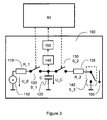
- Figure 3 shows the schematic structure of a patient monitor 100 according to an exemplary embodiment.
- alpha numeric reference signs such as 'R_1', 'S_2', are used to refer to the value of an element such as a resistor, or a state of an element such as a switch.
- the patient state monitor 100 comprises a constant voltage supply 100 of voltage U_0, a charging resistor 115 of resistance R_1, a capacitor 125 of capacity C, the capacitor 125 serving as energy storage, a discharging resistor 135 of resistance R2, and an acceleration switch 140, the acceleration switch 140 acting as motion-sensitive sensor unit.
- an acceleration switch other kinds of switches may be used which are normally open and close temporarily due to motion, such as vibration switch or shock switch.
- the design may further be modified to use switches which are normally closed and open temporarily due to motion.
- the patient state monitor 100 further comprises a charging switch 120 and a coupling switch 130.
- the charging switch 120 as well as the coupling switch 130 are controlled by the controller unit 80 and are typically realized as solid state semiconductor switches, but may also be realized as electromechanical switches such as micro reed relays.
- the patient state monitor 100 further comprises a voltage threshold detector 145, the voltage threshold detector 145 being operatively coupled to the capacitor 125 and to a counter unit 150.
- the voltage threshold detector 145 may, e.g., be realized as a Schmitt trigger or may be realized by a quantitative analogue-to-digital converter, wherein the digital output of the converter is compared to a corresponding threshold number.
- the threshold detector 145 may further comprise additional signal conditioning components such as voltage level converters, filters, or the like.
- the acceleration switch 140 is normally open and is closed if it is exposed to an acceleration a in the direction defined by the measurement vector 160, the acceleration a exceeding a given threshold acceleration.
- Such acceleration switches are, among others, supplied by Assemtech Europe Ltd, UK.
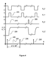
- Figure 4 qualitatively reflects major signals as may be probed in a patient state monitor 100 according to Figure 3 as a function of time t.
- 'o' indicates an open switch while 'c' indicates a closed switch.
- the capacitor 125 is assumed to be fully discharged in an initial state, resulting in the capacitor voltage U_C to be substantially zero.
- the sensor signal SS is made up by the status of the acceleration switch 140 while the patient state signal PS is made up be the capacitor voltage U_C.
- the charging switch 120 is closed periodically, the period defining the monitoring interval 210 of monitoring interval length MT.
- small values are preferable for both the charging resistor 115 and the capacitor 125 in order to achieve a small charging time constant ⁇ _1.
- a small charging current is desirable, resulting in a lower limit for the value R_1 of the charging resistor 115.
- the value R_2 of the discharging resistor 135 may be chosen to 1k ⁇ .
- the purpose of the discharging resistor 135 is to limit the discharging current of the capacitor 125 and may not be required at all if the capacity C of the capacitor 125 is sufficiently small and the acceleration switch 140 is designed for the resulting discharging current.
- curve 215 showing the state of the acceleration switch 140 and the pulse 220 indicates a patient motion. If the patient has not moved within the monitoring interval 210, the capacitor voltage U_C does not substantially change within the corresponding monitoring interval 210, i.e., it substantially stays at the level U_0.
- the capacitor voltage U_C is sampled at the beginning of each monitoring interval 210 virtually immediately prior to closing the charging switch 120 and is compared with a threshold voltage U_T by the threshold detector 145.
- the threshold voltage U_T is chosen such that the capacitor voltage U_C does not fall below the threshold voltage U_T due to leakage of the capacitor 125 but does certainly fall below the threshold voltage U_T if at least one patient motion resulting in closing the acceleration switch 140 occurs in the monitoring interval 210.
- the threshold voltage U_T may be fixed to, e.g., (0.8...0.9) * U_0.
- the binary output of the threshold detector 145 is fed into the counter unit 150.
- the counter unit 150 comprises a counter counting the number N of consecutive monitoring intervals without substantial patient motion and a comparator to compare the counter state N with a threshold number TN. If the patient has moved within the past monitoring interval 210, i.e., if the capacitor voltage U_C is below the threshold voltage U_T, the counter is reset to zero, otherwise the number N is incremented by one.
- the alarming time interval AT is given by the product of the monitoring interval length MT and the threshold number TN. If no patient motion has occurred for TN consecutive monitoring periods 210, an alarm triggering signal is generated by the comparator comprised by the counter unit 150 and is transmitted to the controller unit 80. Along with controlling the acoustical indicator 33 and/or the tactile indicator 35 to generate alarm signals, a corresponding alarm message is displayed on the display 30 and the administration unit 70 is commanded to stop drug administration.
- the capacitor 125 While charging the capacitor 125, the capacitor 125 is decoupled from the acceleration switch 140 via the coupling switch 130 in order to prevent the capacitor 125 to be charged improperly or incompletely due to a patient motion which may occur during charging.
- the alarming time interval AT may, e.g., be set to a typical value of 1h.
- the capacitor voltage U_C typically falls from U_0 below U_T due to leakage even if the acceleration switch is permanently open.
- the length MT of the monitoring interval 210 is therefore chosen to be substantially shorter than the alarming time interval AT.
- capacitor leakage is taken into account by successively lowering the threshold voltage U_T within a monitoring interval such that the capacitor voltage U_C does not fall below the threshold voltage U_T within a monitoring interval because of capacitor leakage.
- the exemplary embodiment of the patient state monitor 100 as described above may be slightly modified for energy efficiency purposes. Instead of closing the charging switch 120 at the beginning of each monitoring period 210, it may be closed in order to recharge the capacitor 125 only if the capacitor voltage U_C has fallen below a charging threshold voltage U_CT.
- the charging threshold voltage U_T is selected such that the capacitor voltage U_C will not fall below the threshold voltage U_T within the following monitoring interval 210 due to capacitor leakage, with U_T ⁇ U_CT ⁇ U_0.
- the patient state monitor 100 of this exemplary embodiment is not designed for providing quantitative information with respect to patient motion but to detect if the patient has moved within a monitoring interval 210.
- the capacity C of the capacitor 125 is considerably larger such that the capacitor is typically not fully discharged if the acceleration switch is temporarily closed due to a patient motion and the capacitor voltage U_C is evaluated quantitatively at the beginning of each monitoring interval.
- the capacitor voltage U_C prior to charging is typically either substantially equal to voltage U_0 nor to substantially equal to zero, but may take any value between zero and U_C, dependent on how often and how long the acceleration switch 140 was closed during the past monitoring interval due to acceleration.
- the capacitor voltage U_C the patient motion level can be assessed quantitatively besides detecting if a patient motion has occurred.
- the charging switch 120 is not closed for fixed periods of time for charging the capacitor 125, but the capacitor voltage U_C is sampled during charging and the charging switch 125 is opened when the capacitor 125 is substantially fully charged.
- Figure 5 shows the schematic structure of a patient monitor 100' according to a further exemplary embodiment.
- the motion-sensitive sensor unit 140' is a switch which may be both statically open or statically closed as long as the patient does not substantially move and may change from 'open' to 'closed' and vice versa due to patient motion.
- the motion-sensitive sensor unit 140' may especially be a tilt switch which is open or closed in dependence of the orientation of a measurement vector 160' with respect to gravity. The state of the tilt switch 140' makes up the sensor signal SS.
- the patient state monitor 100' comprises a resistor 165 serving as a pull-up resistor, resulting in the switch voltage U_S being substantially equal to voltage U_0 with respect to ground if the tilt switch 140' is open and to be substantially zero with respect to ground if the tilt switch 140' is closed.
- the patient monitor 100' further comprises a comparison unit 170, the comparison unit 170 comprising a two-stage 1 Bit shift register for storing the state of the tilt switch 140' and an XOR-logic.
- the patient state monitor 100' further comprises a counter unit 150'.
- the patient state monitor 100' may comprise further supplementary components such as a Schmitt trigger for converting the switch voltage U_S into a binary signal.
- step 400 the state of the tilt switch 140' is stored in the first register Reg_1 of the shift register of comparison unit 170.
- the monitoring interval having a monitoring interval length MT in step 405 the contents of the first register Reg_1 is shifted to the second register Reg 2 and while the current state of the tilt switch 140' is stored in the first register Reg_1 in step 410.
- step 415 the contents of the first register Reg_1 and the second register Reg_2 are compared by an XOR-Logic comprised by the comparison unit 170. If the contents of both registers Reg_1 and Reg_2 is different, i.e., either of the registers comprise a 'Boolean 0' while the other of the registers comprises a Boolean '1', it can be assumed that the patient has moved in the past monitoring interval. In this case, a counter counting the number N of consecutive monitoring intervals without substantial patient motion, the counter being comprised by the counter unit 150', is reset in step 420 and a new monitoring interval is started with step 405.
- both registers Reg_1 and Reg_2 are identical, i.e. both of the registers either comprise a 'Boolean 1' or a 'Boolean 0', the patient may not have moved within the past monitoring interval, or the patient may have moved such that the state of the tilt switch 140' in step 410 is identical to the state of the tilt switch 140' in step 400.
- the counter comprised by the counter unit 150' is incremented by one in step 425 and the counter state N is compared with a threshold number TN in step 430 by a comparator comprised by the counter unit 150'. If the counter state equals the threshold number TN, an alarm triggering signal is generated by the counter unit 150' and transmitted to the controller unit in step 435. Otherwise a new monitoring interval is started with step 405.
- a patient motion within a monitoring interval is not necessarily detected according to this type of exemplary embodiment.
- the threshold number TN is preferably selected such that the probability of only undetected patient motion within TN consecutive monitoring intervals is virtually zero. For example, assuming a monitoring interval length MT of 3min, the threshold number TN may be chosen to 40.
- Figure 7 shows the schematic structure of a patient monitor 100" according to a further exemplary embodiment.
- the motion-sensitive sensor unit is a piezo electric acceleration sensor 200 generating a charge Q when being accelerated, the charge Q being proportional to the acceleration.
- the patient state monitor 100" comprises a charge amplifier 205, the charge amplifier 205 converting the charge Q into a charge proportional voltage U_Q.
- the charge Q makes up the sensor signal SS.
- the patient state monitor 100" further comprises a pulse former 210, the pulse former 210 generating a triggering pulse upon a falling edge or rising edge of the charge proportional voltage Q_C.
- the output of the pulse former 210 makes up the patient state signal PS.
- the patient state monitor 100" further comprises a sampling timer 220, and a hold off-timer 225.
- the hold-off timer 225 is adapted to selectively energize the charge amplifier 205 and the pulse former 210.
- Both the sampling timer 220 and the hold-off timer comprises a timer and a comparator to compare the timer state with a threshold time and to generate an output signal resulting from the comparison.
- the corresponding threshold time is made up by the maximum sampling interval length ST_max
- the hold-off timer the corresponding threshold time is made up by the non-sampling interval length NST.
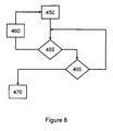
- step 450 a sampling interval is started by resetting and starting the sampling timer 200, the sampling timer 200 counting the sampling time t.
- step 455 the output of the pulse former 210 is sampled.
- a pulse generated by the pulse former 210 is indicative for either of a positive or negative pulse of the charge proportional voltage U_Q as a consequence from an acceleration pulse measured by the piezo electric acceleration sensor 200.
- the hold-off timer disenergizes the charge amplifier 205 and the pulse former 210 and stops the sampling timer 220, followed by waiting for a non- sampling interval having a non sampling interval length NST in step 460.
- the charge amplifier 205 and the pulse former 205 are reenergized and a new sampling interval is started with step 450.
- the sampling time t as measured by the sampling timer 220 is compared to the maximum sampling interval length ST_max in step 465. If the sampling time t equals the maximum sampling interval length ST_max, an alarm triggering signal is generated in step 470. Otherwise, the output of the pulse former 210 is sampled again in step 455.
- the non sampling interval length NST is chosen such that at least one patient motion occurs during the sampling interval if the patient is not in a coma.
- the non-sampling interval length NST may be chosen to 15 min and the maximum sampling interval length ST_max may be chosen to 45min, resulting in an alarming time interval AT of 1h.
- the non sampling interval length NST may further be adaptive and may especially be shorter during night time as compared to daytime or may not be present at all.
- the sensor signal is evaluated quantitatively and the patient state signal PS is given by the average acceleration level within a sampling interval and the pre-defined motion level is given by a threshold average acceleration level.
- the alarming time interval AT is initially set to a long time of e.g., 6 hours according to the configuration of a health care professional. Subsequently, the sensor signal SS is processed and evaluated for an adoption time interval of, e.g., 1 month in order to determine the patient's individual motion habits and amount of motion. An appropriate value for the alarming time interval AT is subsequently be determined as the longest time interval LT without substantial patient motion within the adoption time interval. An additional safety margin is added to this value to make up the alarming time in order avoid false alarms.
- the safety margin may be a fixed amount of time of, e.g., 30 min, which is added to longest time interval LT without substantial patient motion within the adoption time interval or may be defined in dependence of the longest time interval LT without substantial patient motion within the adoption time interval by multiplying it with a safety factor of, e.g., 1.1, the safety factor being larger than one.
- the alarm triggering signal may further or alternatively be transmitted to a separate user interface, to a cell phone, or the like.
Abstract
Method for detecting patient motion below a pre-defined motion level.
Description
- The present invention is related to an administration device for the continuous or quasi-continuous administration of a liquid drug over an extended time period and to a method for supervising such an administration device.
- Continuous Subcutaneous Insulin Infusion (CSII) is the basis for a state-of-the-art therapy of insulin-dependent diabetes mellitus. In this therapy, a diabetic patient carries a miniaturized infusion pump night and day and preferably concealed from view. The infusion pump administers insulin by a cannula, the cannula being, e.g., made from medical-grade stainless steel or Teflon, into the subcutaneous tissue. The insulin pump administers insulin in a continuous or quasi-continuous way according to a patient-specific and time-of-day dependent basal profile in order to cover the patient's basal (i.e., meal-independent) insulin need. In addition, the pump is adapted to administer comparatively large insulin boli on demand which are required for covering the intake of food, namely carbohydrates, and to correct for undesirably high blood glucose values. Infusion devices which are adapted fort the CSII therapy of diabetes mellitus are disclosed, e.g., in
US 6878132 . - A general concern associated with the diabetes therapy based on insulin administration is the danger of hypoglycemia. While the number of potential reasons for this phenomenon is high, it is usually associated with a mismatch between blood glucose level and blood insulin level, with the blood insulin level being too high. The effect of hypoglycemic conditions may vary from a lack of concentration to severe perceptual disturbances, to coma and finally to death. Under normal circumstances, the immediate intake of fast-acting carbohydrates is a sufficient measure. However, in some cases, a diabetic may fall into a hypoglycemic coma very fast without having a chance to act properly.
- In a situation of hypoglycemic coma, it is highly desirable to provide an alarm signal in order to get emergency support as fast as possible. It is further desirable to stop drug administration almost immediately in order not to worsen the situation. Therefore, state-of-the-art insulin pumps may comprise a 'dead man's control' which automatically triggers the generation of an audible alarm signal and stops insulin administration if no user interaction with the pump has occurred for a given alarming time in which a user interaction, such as a bolus administration, can be assumed to occur. In order to avoid false alarms, the alarming time may, for example, be as along as 12 hours. This is, however, often found to be inappropriate in different ways: On the one hand the alarming time may be too short: When sleeping long, e.g. at a weekend, even a rather long alarming time may be too short and cause 'false alarms'. Such false alarms are generally inconvenient and are even found to be dangerous if insulin administration is stopped due to a false alarm. On the other hand, the alarming time may be too long: If the situation of a hypoglycemic coma occurs shortly after a user interaction, alarming and potentially stopping the insulin administration are triggered only with a delay of many hours.
- It is an objective of the present invention to provide administration devices for the continuous or quasi-continuous administration of liquid drugs, such as insulin, which improve the state-of-the-art by ensuring a short delay time for alarming in case of the patient being in a coma while avoiding false alarms by considering patient motion and assuming that a patient is likely to be in a coma if patient motion is below a predefined motion level.
- In the following, some terms are defined as they are used in the context of the present invention.
- The term 'motion-sensitive sensor unit' refers to sensor units which are reactive on motion. A motion-sensitive sensor unit may temporarily generate a sensor signal SS as a direct consequence of motion and/or change of motion, such as an acceleration sensor. Alternatively or additionally, the motion sensitive may continuously generate a sensor signal SS which is changed or modified by motion, such as tilt sensor, the tilt sensor generating a sensor signal SS in dependence of the orientation of a measurement vector with respect to gravity.
- The term 'sensor unit' refers to both a single sensor as well as to an arrangement of multiple sensors, such as an arrangement of at least two single acceleration sensors, each single sensor being associated with a different measurement vector. In such an arrangement, the single sensors may operate according to one or more than one physical principle. Accordingly, the sensor signal SS may be a single signal or a vector of multiple signals.
- The term 'derived' in the context of a signal generally refers to a signal which is obtained from another primary signal by processing means such as amplifying, threshold detection, analogue to digital conversion, filtering, or the like. A derived signal may also be identical with the corresponding primary signal.
- The term 'patient motion level' refers to the general amount of patient motion over time. Patient motion may be assessed based on diverse criteria such peak acceleration values, average acceleration values, mean time between consecutive patient motions, duration of continuous patient motions, duration of time intervals without patient motion, or the like.
- An administration device for the administration of a liquid drug over an extended time period according to the present invention comprises:
- a) an administration unit (70),
- b) a housing (10), the housing (10) comprising the administration unit (70), the housing (10) being adapted to be carried by a patient over an extend time period,
- c) a controller unit (80), the controller unit (80) controlling operation of the administration unit (70), the controller unit (80) being adapted to receive an alarm triggering signal,
- d) at least one alarming unit (33, 35), the at least one alarming unit (33, 35) being coupled to the controller unit (80), the at least one alarming unit (33, 35) being adapted to generate at least one alarm signal on reception of the alarm triggering signal by the controller unit (80), and
- e) a patient state monitor (100, 100', 100"), the patient state monitor (100, 100', 100") comprising a motion-sensitive sensor unit (140, 140', 200), the motion-sensitive senor unit (140, 140', 200) being reactive on patient motion, the patient state monitor (100, 100', 100") being adapted to process a sensor signal (SS) generated by the motion-sensitive sensor unit (140, 140', 200), the patient state monitor (100, 100', 100") being adapted to generate an alarm triggering signal and to transmit the alarm triggering signal to the controller unit (80) if processing of the sensor signal (SS) indicates a patient motion level below a pre-defined motion level.
- In preferred embodiments, the administration device comprises further elements known in the art such as a drug reservoir, a user interface, a power supply, at least one data interface.
- The controller unit typically comprises elements which are obvious for the man skilled in the art, such as such as ASICS, micro controllers, memory circuits, clock and timer circuits, general digital and analogue circuity, and the like. Typically, the controller unit comprises at least one micro controller.
- In preferred embodiments, the alarming unit comprises at least one of an audio alarm generator, such as a buzzer or loud speaker, and a tactile alarm generator, such as a pager vibrator. In especially preferred embodiments, the at least one alarming unit is comprised by the housing. Alternatively or additionally, the alarming unit may comprise remote alarm generators, such as dedicated alarming devices carried by a third person. In preferred embodiments, the at least one alarming unit further serves as indication unit for general control and operation feedback purposes.
- In some preferred embodiments, all components of the administration device are comprised by and/or coupled to the housing. In alternatively preferred embodiments, however, some components are comprised by and/or coupled to a least one further housing. For example, the controller unit may, totally or in part, be comprised by an additional controller housing, wherein the controller unit and the administration unit are adapted for preferably wireless communication. Similarly, a preferably present user interface may, totally or in part, be comprised by a user interface housing, the user interface housing being separate from the housing, in order to enable convenient and discrete operation. Providing further housings is especially favorable if the housing is adapted to be attached substantially directly at the infusion site, e.g., as a patch or further locations which can not guaranteed to be accessible in an easy and discrete way for user interaction purposes.
- According to some preferred embodiments, the patient state monitor consists of a motion-sensitive sensor unit. According to alternatively preferred embodiments, the patient state monitor comprises further elements such as signal conditioning circuity, counters, timers, shift registers, energy storages, or the like as described in grater detail below in the framework of exemplary embodiments. The patient state monitor may, at least in part, be integral with the controller unit.
- In some preferred embodiments, the motion-sensitive sensor unit is rigidly coupled to the housing. For this kind of design, any motion of the housing is directly transferred to the motion-sensitive sensor unit.
- In alternatively preferred embodiments, the motion-sensitive sensor unit is comprised by and/or coupled to a motion sensor unit housing, the motion sensor unit housing being separate from the housing. For example, the motion-sensitive sensor unit may be comprised by and/or rigidly coupled to a dedicated motion sensor unit housing, the motion sensor unit housing being adapted to be carried, e.g., like a wrist watch. Besides the motion-sensitive sensor unit, the motion sensor unit housing may comprise further elements of the patient state monitor. The motion sensor unit housing may especially comprise a preferably wireless motion sensor unit data interface, the motion sensor unit data interface being operatively coupled to the motion-sensitive sensor unit, the motion sensor unit data interface being adapted to transmit the sensor signal SS and/or at least one signal derived from the sensor signal SS. Providing a dedicated motion sensor unit housing such as a wrist watch like motion sensor unit housing allows to couple the motion-sensitive sensor unit to a patient's arm or leg which are typically more likely to move than the patient's body, especially while sleeping.
- In preferred embodiments, the motion-sensitive sensor unit comprises at least one of a tilt sensor, a vibration sensor, a shock sensor, and an acceleration sensor. In further embodiments, other kinds of motion-sensitive sensors, such as gyroscopic sensors, are used.
- In preferred embodiments, the motion-sensitive sensor unit comprises at least one binary switching sensor such as an acceleration switch, a vibration switch or a tilt switch. The corresponding sensor signal SS reflects the state of the sensor, i.e., 'open' or closed'. In especially preferred embodiments comprising at least one binary switching sensor, the motion-sensitive sensor unit comprises at least two binary switching sensors, the at least two binary switching sensors having different measurement axes. The measurement axes may especially be substantially perpendicular to each other. The at least two binary switching sensors may be electrically parallel to form a resulting switch, the resulting switch being closed if at least one of the binary switching sensors is closed.
- In alternatively preferred embodiments, the motion-sensitive sensor unit comprises at least one sensor generating a quantitative sensor signal SS, such as a piezo acceleration sensor, a capacitive acceleration sensor or a gyroscopic sensor. If the motion-sensitive sensor unit especially comprises a piezo electric acceleration sensor, a charge amplifier circuit as known in the art may be used for charge-to-voltage conversion purposes, allowing the quantitative evaluation of acceleration in addition to the qualitative detection of patient motion. Since the goal, however, is to detect the occurrence of substantial patient motion, a charge-generating piezo electric sensor may also be directly coupled to an analogue to digital conversion circuit such as a Schmitt trigger, or the like, in order to obtain a binary signal.
- According to some preferred embodiments comprising a motion-sensitive sensor unit comprising at least two single motion-sensitive sensors, the signals generated by the at least two motion-sensitive sensors are, at least in part, evaluated independently. Providing a motion-sensitive sensor unit comprising at least two single motion-sensitive sensors is especially advantageous in order to avoid false alarms because of patient motions not being detected by a motion-sensitive sensor having one fixed measurement axis.
- In preferred embodiments, the patient state monitor comprises an energy storage and the motion-sensitive sensor unit is adapted to modify an energy E stored by the energy storage. In especially preferred embodiments, the energy storage is a capacitor and the energy E is stored in the electrical field of the capacitor. In alternative embodiments, other types of energy storages such as coils or mechanical springs may be used as energy storage.
- In especially preferred embodiments comprising a capacitor as energy storage, the motion-sensitive sensor unit comprises at least one binary switching sensor, wherein closing the at least one binary switching sensor results in fully or partly charging or discharging the capacitor.
- In preferred embodiments, the controller unit is adapted to control the administration unit to stop drug administration on reception of the alarm triggering signal. Stopping drug administration is desirably, e.g. in the framework of diabetes therapy by CSII in order not to worsen the situation in case of a hypoglycemic coma.
- In preferred embodiments, the patient state monitor is adapted to be selectively deactivated. In especially preferred embodiments, the patient state monitor may be automatically deactivated for given periods of time per day and/or for given days of a week. For example, the patient state monitor may be automatically deactivated during night time in order to avoid false alarms. In especially preferred embodiments, the patient state monitor is adapted to be manually deactivated by the patient for a given time interval and/or until a given time of day. In especially preferred embodiments, the patient state monitor is further adapted to be fully deactivated by the patient and/or a healthcare professional. In especially preferred embodiments comprising a patient state monitor that is adapted to be selectively deactivated, the administration device further comprises a dead man's control unit, the dead man's control unit being adapted to be activated upon deactivation of the patient state monitor. A dead man's control unit may further be provided in addition to the patient state monitor for safety and redundancy purposes.
- In preferred embodiments, the patient state monitor is, at least in part, adapted to be discontinuously energized. In the context of applications such as diabetes therapy by CSII, power consumption is generally critical as the power supply is one of the major components determining the administration device size.In some especially preferred embodiments, the patient state monitor is, at least in part, adapted to be energized only for defined sampling points in time and/or during given sampling intervals and may be disenergized otherwise. The sensor signal generated by the motion-sensitive sensor unit is preferably not processed if the patient-state monitor is, at least in part, disenergized.
- Discontinously energizing may affect the patient state monitor as a whole or may affect only some especially power consuming components of the patient state monitor, such as the motion-sensitive senor and signal condition circuity, while not affecting other components such as counters.
- It is another objective of the present invention to provide a method for detecting a patient motion level below a pre-defined motion level. A method for detecting a patient motion level below a predefined motion level in accordance with the present invention may especially be used for supervising an administration device according to the present invention as described above.
- A method for detecting a patient motion level below a pre-defined motion level according to the present invention comprises the steps of:
- a) providing an administration device, the administration device being adapted to be carried by a patient and being adapted for drug administration over an extended period of time, the administration device comprising a motion-sensitive senor unit (140, 140', 200), the motion sensitive sensor unit (140, 140,', 200) being reactive on patient motion,
- b) processing a sensor signal (SS) generated by the motion-sensitive sensor unit (140, 140', 200) and generating an alarm triggering signal if processing of the sensor signal (SS) indicates a patient motion level below a pre-defined motion level.
- The pre-defined motion level is given by a minimum motion level that can be expected by a conscious human. A pre-defined motion level may be different for different patients, for different situations, for different times of day (e.g., for daytime and nighttime), and so on.
- In preferred embodiments, the pre-defined motion level is defined by length of time periods without patient motion and the method comprises generating an alarm triggering signal if processing of the sensor signal SS indicates no patient motion for a given alarming time interval AT. For this kind of embodiment, the pre-defined motion level is given by the alarming time period AT.
- In preferred embodiments, the method further comprises the step of generating at least one alarm signal upon generation of the alarm triggering signal.
- In especially preferred embodiments comprising the generation of at least one alarm signal, the at least one alarm signal comprises at least one of an audible alarm signal and a tactile alarm signal. In especially preferred embodiments, the at least one alarm signal is generated by at least one alarming unit, the at least one alarming unit being comprised by and/or coupled to the administration device. In preferred embodiments, the alarm signal may be generated remotely, e.g., by an alarming unit comprised by a remote controller. In especially preferred embodiments, the alarm signal may be generated by commercial devices such as a cell phone carried by a health care professional and/or a person other than the patient.
- In preferred embodiments, the method comprises modifying the pre-defined motion level. In especially preferred embodiments involving an alarming time interval AT, the method comprises modifying the alarming time interval AT by a patient and/or a healthcare professional in order to adopt the alarming time interval AT to the patient's individual situation and life style. For example, for a patient being a craftsman a much shorter alarming time interval AT may be appropriate as compared to an office worker who typically spends several hours sitting at a desk with very little motion.
- In preferred embodiments, a set of at least two different pre-defined motion levels is provided and the method comprises manually or automatically selecting either of the at least two motion pre-defined levels.
- In especially preferred embodiments comprising modifying the pre-defined motion level, the method comprises modifying the pre-defined motion level based on at least one of time of day, day of week, and past patient motion. For example, the method involves an alarming time interval AT, the method comprise automatically switching the alarming time interval AT between a first alarming time during daytime and a second alarming time during night time, the second alarming time being larger than the first alarming time. In this way, a short alarming delay may be achieved during daytime where a lot of patient motion is typical to occur without causing false alarms during night time and especially during sleep where less patient motion is typical to occur. Similarly, the alarming time interval AT may be automatically modified to be different for working days and weekend days.
- In especially preferred embodiments, the pre-defined motion level may be modified based on past patient motion. For example, if a diabetic person is newly equipped with an administration device according to the present invention and the method involves an alarming time interval AT, the alarming time interval AT may first be set to a comparatively long default value, of, e.g., 6h. Subsequently, the sensor signal SS may be processed and evaluated for an adoption time interval of, e.g., 1 month in order to determine the patient's individual motion habits and motion level. The initial alarming time may subsequently be modified based on the longest time interval without substantial patient motion within the adoption time interval or based on a quantile, such as the 95% quantile of all periods of time without substantial patient motion within the adoption time interval.
- In addition to or alternatively to providing a dedicated adoption time interval, the patient motion level may be monitored and the pre-defined motion level may be adapted to automatically adapt the pre-defined motion level to change in circumstances such as a change from work to holidays and vice versa and/or changes in habits or lifestyle of the patient.
- In preferred embodiments, the method comprises sampling a patient state signal, the patient state signal being identical with or being derived from the sensor signal SS at defined sampling points in times, the sampling points in time defining monitoring intervals. In especially preferred embodiments, an alarming time interval AT is defined by the product of the monitoring interval length MT and a threshold number TN, such that an alarm triggering signal is generated if the patient has not moved for TN consecutive monitoring intervals.
- In some especially preferred embodiments, the sensor signal SS is continuous and is changed or modified as a result of patient motion, such as the signal generated by a tilt sensor. In this case, the method preferably comprises assuming that the patient has not moved within a given monitoring interval if the patient state signal PS is substantially identical at the two consecutive sampling points in time bordering the given monitoring interval. If for example, the motion-sensitive sensor unit comprises a tilt switch, the method preferably comprises assuming that the patient has not moved within a given monitoring interval if the tilt switch is open at both of the two consecutive sampling points in time bordering the given monitoring interval or is closed at both of the consecutive sampling points in time bordering the given monitoring interval.
- In alternatively preferred embodiments, the sensor signal SS is generated temporarily as a direct consequence of patient motion and/or change of patient motion, such as the signal generated by an acceleration sensor. In this case, the method preferably comprises modifying the patient state signal PS based on the sensor signal SS during a monitoring period and sampling the patient stat signal PS at the monitoring points in time.
- Sampling a patient state signal PS at defined monitoring points in time, the monitoring points in time defining monitoring intervals, is especially advantageous with respect to energy consumption in contrast to sampling a patient state signal PS continuously.
- In preferred embodiments, the method comprises modifying the energy E stored in an
energy storage 125, wherein modifying the energy E is, at least in part, triggered by patient motion. The patient state signal PS is preferably correlated with the energy E. In especially preferred embodiments, the method comprises modifying the energy E to change between a first energy E_1 and a second energy E_2, the first energy E_1 being different from the second energy. In especially preferred embodiments, the method comprises modifying the energy E stored by a capacitor, the capacitor making up the energy storage and the capacitor voltage U_C making up the patient state signal PS. In especially performed embodiments involving an alarming time interval AT, the alarming time interval AT being defined by the product of a monitoring interval length and a threshold number TN, the motion-sensitive sensor comprises an acceleration switch and the method comprises performing the steps of: - a) sampling the capacitor voltage U_C
- b) comparing the capacitor voltage U_C with a threshold voltage U_T
- c1) if the capacitor voltage U_C is below the threshold voltage U_T
- c11) resetting a counter, the counter counting the number N of consecutive monitoring intervals without substantial patient motion
- c11) charging the capacitor to a capacitor voltage U_C = U_0, followed by starting a new monitoring interval
- c12) during the monitoring interval, discharging the capacitor to a voltage U_C = 0 if the acceleration switch is closed.
- c13) continuing with step (a) at the end of the monitoring interval
- c2) if the capacitor voltage U_C is above the threshold voltage U_T
- c21) incrementing the counter state N of the counter by one
- c22) if the counter state N equals a threshold number TN, generating an alarm triggering signal
- c23) if the counter state N is lower than the threshold number TN, continuing with step c11)
- In preferred embodiments, the method comprises sampling a patient state signal PS, the patient state signal PS being identical with or being derived from the sensor signal SS, during sampling intervals, the sampling intervals alternating with non-sampling intervals. During sampling interval, the method preferably comprises sampling the patient state signal PS continuously or quasi-continously.
- In especially preferred embodiments, the sampling interval length ST is not constant but is limited not to exceed a maximum sampling interval length ST_max while the non-sampling interval length NST is constant. In especially preferred embodiments, the method comprises performing the steps of
- a) resetting and starting a sampling timer, the sampling timer measuring the sampling time t during a sampling interval
- b) continuously or quasi continuously sampling the patient state signal PS until
- b1) the sampling time t equals the maximum sampling interval length ST_max or
- b2) the patient state signal PS indicates a substantial patient motion
- c1) if the sampling time t does not equal the maximum sampling interval length ST_max
- c11) stopping the sampling timer and waiting for a non-sampling interval, the non sampling interval having a given non sampling interval length NST, followed by
- c12) continuing with step (a)
- c2) if the sampling time t equals the maximum sampling interval length ST_max, generating an alarm triggering signal.
- For this embodiment, the pre-defined motion level is defined by a maximum time without patient motion and an alarming time interval AT is given by the sum of the maximum sampling interval length ST_max and the non sampling interval length NST. The maximum sampling interval length ST_max is chosen such that at least one patient motion occurs during a sampling interval if the patient is not in a coma. For example, the non-sampling interval length NST may be chosen to 15 min and the maximum sampling interval length ST_max may be chosen to 45 min, resulting in a an alarming time interval AT of 1h.
- Non-sampling intervals are especially preferable with respect to energy consumption. In especially preferred embodiments comprising non-sampling intervals, the method comprises energizing a patient state monitor, at least in part, discontinuously. For example, a motion-sensitive sensor unit and additional signal conditioning circuity may not be energized during non-sampling intervals.
- In preferred embodiments, the method further comprises controlling an administration unit (70), the administration unit (70) being comprised by the administration device, to stop drug administration along with generation of the alarm triggering signal.
- In the following, exemplary embodiments of administration devices according to the present invention and exemplary embodiments of methods for detecting a patient motion level below a pre-defined motion level according to the present invention are described in greater detail with reference to the figures.
-
Figure 1 shows an administration device according to an exemplary embodiment of the invention. -
Figure 2 shows the internal functional structure of an administration device as shown inFigure 1 . -
Figure 3 shows the schematic structure of an exemplary patient state monitor of an exemplary administration device. -
Figure 4 qualitatively shows major signals as may be probed in a patient state monitor according toFigure 3 . -
Figure 5 shows the schematic structure of a further exemplary patient state monitor of an exemplary administration device. -
Figure 6 shows a flow diagram for the operation of a patient state monitor according toFigure 5 . -
Figure 7 shows the schematic structure of a further exemplary patient state monitor of an exemplary administration device. -
Figure 8 shows a flow diagram for the operation of a patient state monitor according toFigure 7 . -
Figure 1 shows an administration device according to exemplary embodiments of the invention,Figure 2 reflects the internal structure of the administration device in a schematic way. Such an embodiment is especially suited and designed for the insulin administration in the framework of diabetes therapy using CSII and the following description of exemplary embodiments refers to diabetes therapy. In the following, reference is first made toFigure 1 and toFigure 2 . - The administration device comprises a
housing 10, thehousing 10 enclosing the other device components. Thehousing 10 is adapted to be worn by a patient both night and day and to be carried without attracting attention, e.g., in a belt holster. It may further be carried concealed from view, e.g., in a trousers pocket, like a necklace, or the like. - The administration device comprises a
drug reservoir 20, aninfusion line 29 and aninfusion line adapter 25, the infusion line adapter coupling theinfusion line 29 to thedrug reservoir 20. Thehousing 10, thedrug reservoir 20 and theinfusion line adapter 25 are designed to form a sealed and watertight unit in the assembled state shown inFigure 1 . Theinfusion line 29 is connected to an infusion cannula (not visible in the figures). The infusion cannula is placed in the subcutaneous tissue and is replaced by the patient every few days. Thedrug reservoir 20 may, for example, comprise 3.15ml of insulin, with each ml of insulin corresponding to 100 International Units (IU) of insulin. - The exemplary administration devices comprises a
user interface 50, theuser interface 50 comprising fourpushbuttons display 30, anacoustic indicator 33 in form of a buzzer and atactile indicator 35 in form of a pager vibrator. Thedisplay 30 is a graphical Liquid Chrystal Display (LCD) and is used to provide multiple information well known for this kind of device, such as operation mode information, time and date, drug bolus information, current basal infusion rate information, menu items for programming the administration device, alerts and error messages, and the like. Theacoustic indicator 33 and thetactile indicator 35 are provided for generating non-visual user feedback signals and further serve as alarming unit. - For performing the drug administration, a
pump unit 60 and asupervision unit 63 are provided. In this exemplary embodiment, thepump unit 60 comprises a motor-driven spindle drive and thesupervision unit 63 comprises a force sensor and a rotary encoder. In combination, thedrug reservoir 20, thepump unit 60 and thesupervision unit 63 form theadministration unit 70. Several suitable designs for theadministration unit 60 are known in art and may be designed, for example according to the disclosure ofEP1124600B1 orEP0991440B1 . - The operation of the administration device is controlled by the
controller unit 80. TheController unit 80 is realized as an electronics circuit and comprises all the elements typically comprised by the control circuit of this kind of administration devices, such as one or multiple micro controllers, static and dynamic memory, a clock circuit, a power circuit for controlling thepump unit 60, safety circuits, and the like. - The
controller unit 80 is connected to a power supply such as a rechargeable or non-rechargeable battery. - The administration device further comprises two bidirectional data interfaces, namely an Infra Red IR data interface 90 and an Radio Frequency
RF data interface 95, according, e.g, to the BLUETOOTH standard for multiple configuration, remote control and data exchange purposes which are typical for this kind of device. - The exemplary administration device further comprises a
patient state monitor patient state monitor patient state monitor Figure 1 andFigure 2 and as described above may be identical for all exemplary embodiments of the invention. In addition, it has to be understood that the exemplary embodiments of thepatient state monitor 100, 100' and the exemplary methods for controlling the operation of the administration device are not limited to administration devices of this specific structure. - It should be noted that the
patient state monitor controller unit 80, while thepatient state monitor controller unit 80 in the technical implementation. The program flow for the operation of thepatient state monitor controller unit 80 for all exemplary embodiments described below in greater detail. -
Figure 3 shows the schematic structure of apatient monitor 100 according to an exemplary embodiment. - In the following, when referring to dedicated electronics components like resistors or switches as such, numeral reference signs are used while alpha numeric reference signs, such as 'R_1', 'S_2', are used to refer to the value of an element such as a resistor, or a state of an element such as a switch.
- The patient state monitor 100 comprises a
constant voltage supply 100 of voltage U_0, a chargingresistor 115 of resistance R_1, acapacitor 125 of capacity C, thecapacitor 125 serving as energy storage, a dischargingresistor 135 of resistance R2, and anacceleration switch 140, theacceleration switch 140 acting as motion-sensitive sensor unit. Instead of an acceleration switch, other kinds of switches may be used which are normally open and close temporarily due to motion, such as vibration switch or shock switch. The design may further be modified to use switches which are normally closed and open temporarily due to motion. - The patient state monitor 100 further comprises a charging
switch 120 and acoupling switch 130. The chargingswitch 120 as well as thecoupling switch 130 are controlled by thecontroller unit 80 and are typically realized as solid state semiconductor switches, but may also be realized as electromechanical switches such as micro reed relays. The patient state monitor 100 further comprises avoltage threshold detector 145, thevoltage threshold detector 145 being operatively coupled to thecapacitor 125 and to acounter unit 150. Thevoltage threshold detector 145 may, e.g., be realized as a Schmitt trigger or may be realized by a quantitative analogue-to-digital converter, wherein the digital output of the converter is compared to a corresponding threshold number. Thethreshold detector 145 may further comprise additional signal conditioning components such as voltage level converters, filters, or the like. - The
acceleration switch 140 is normally open and is closed if it is exposed to an acceleration a in the direction defined by themeasurement vector 160, the acceleration a exceeding a given threshold acceleration. Such acceleration switches are, among others, supplied by Assemtech Europe Ltd, UK. - In the following, operation of the patient state monitor 100 is described with reference to both
Figure 3 andFigure 4. Figure 4 qualitatively reflects major signals as may be probed in a patient state monitor 100 according toFigure 3 as a function of time t. For all switches, 'o' indicates an open switch while 'c' indicates a closed switch. Thecapacitor 125 is assumed to be fully discharged in an initial state, resulting in the capacitor voltage U_C to be substantially zero. The sensor signal SS is made up by the status of theacceleration switch 140 while the patient state signal PS is made up be the capacitor voltage U_C. - As indicated by the
curve 205, the chargingswitch 120 is closed periodically, the period defining themonitoring interval 210 of monitoring interval length MT. The closing time of the chargingswitch 120 is generally short, but is sufficient to charge thecapacitor 125 to a capacitor voltage U_C which is substantially equal to the voltage U_0 via the chargingresistor 115, resulting the energy E stored by the capacitor to be
- For example, the
capacitor 125 may be designed to have a value of C=100pF while the chargingresistor 115 may be designed to have a value of R_1=100kΩ, resulting in a charging time constant of τ_1 = R_1*C = 10µsec and the closing time of chargingswitch 120 may be chosen as 4* τ_1. On the one hand, small values are preferable for both the chargingresistor 115 and thecapacitor 125 in order to achieve a small charging time constant τ_1. On the other hand, a small charging current is desirable, resulting in a lower limit for the value R_1 of the chargingresistor 115. - After charging the
capacitor 125, and assuming thecoupling switch 130 to be closed, closing theacceleration switch 140 results in thecapacitor 125 to be discharged via the dischargingresistor 135, resulting in the capacitor voltage U_C and thus the energy E stored by thecapacitor 125 after discharging to fall substantially to E = E_2 =0. The dimension of the discharging resistor R_2 is such that the discharging time constant τ_2 = R_2*C is short enough to ensure substantially full discharging of thecapacitor 125 if theacceleration switch 140 is closed for a time of some microseconds. With a dimension of the capacitor as given above, the value R_2 of the dischargingresistor 135 may be chosen to 1kΩ. The purpose of the dischargingresistor 135 is to limit the discharging current of thecapacitor 125 and may not be required at all if the capacity C of thecapacitor 125 is sufficiently small and theacceleration switch 140 is designed for the resulting discharging current. - In
Figure 4 ,curve 215 showing the state of theacceleration switch 140 and thepulse 220 indicates a patient motion. If the patient has not moved within themonitoring interval 210, the capacitor voltage U_C does not substantially change within the correspondingmonitoring interval 210, i.e., it substantially stays at the level U_0. - As indicated by the curve 'S', 230, the capacitor voltage U_C is sampled at the beginning of each
monitoring interval 210 virtually immediately prior to closing the chargingswitch 120 and is compared with a threshold voltage U_T by thethreshold detector 145. The threshold voltage U_T is chosen such that the capacitor voltage U_C does not fall below the threshold voltage U_T due to leakage of thecapacitor 125 but does certainly fall below the threshold voltage U_T if at least one patient motion resulting in closing theacceleration switch 140 occurs in themonitoring interval 210. The threshold voltage U_T may be fixed to, e.g., (0.8...0.9) * U_0. - The binary output of the
threshold detector 145 is fed into thecounter unit 150. Thecounter unit 150 comprises a counter counting the number N of consecutive monitoring intervals without substantial patient motion and a comparator to compare the counter state N with a threshold number TN. If the patient has moved within thepast monitoring interval 210, i.e., if the capacitor voltage U_C is below the threshold voltage U_T, the counter is reset to zero, otherwise the number N is incremented by one. - The alarming time interval AT is given by the product of the monitoring interval length MT and the threshold number TN. If no patient motion has occurred for TN
consecutive monitoring periods 210, an alarm triggering signal is generated by the comparator comprised by thecounter unit 150 and is transmitted to thecontroller unit 80. Along with controlling theacoustical indicator 33 and/or thetactile indicator 35 to generate alarm signals, a corresponding alarm message is displayed on thedisplay 30 and theadministration unit 70 is commanded to stop drug administration. - While charging the
capacitor 125, thecapacitor 125 is decoupled from theacceleration switch 140 via thecoupling switch 130 in order to prevent thecapacitor 125 to be charged improperly or incompletely due to a patient motion which may occur during charging. - The monitoring interval length MT may principally be identical with the alarming time interval AT, resulting in the TN=1. However, this requires the
capacitor 125 to be virtually free from leakage. The alarming time interval AT may, e.g., be set to a typical value of 1h. During this period of time, the capacitor voltage U_C typically falls from U_0 below U_T due to leakage even if the acceleration switch is permanently open. The length MT of themonitoring interval 210 is therefore chosen to be substantially shorter than the alarming time interval AT. Depending on the leakage properties of thecapacitor 125, the monitoring interval length may, e.g, be chosen to be 3min. This results in the threshold number TN=20 for the alarming time interval AT being 1h. According to a modification of this exemplary embodiment, capacitor leakage is taken into account by successively lowering the threshold voltage U_T within a monitoring interval such that the capacitor voltage U_C does not fall below the threshold voltage U_T within a monitoring interval because of capacitor leakage. - The exemplary embodiment of the patient state monitor 100 as described above may be slightly modified for energy efficiency purposes. Instead of closing the charging
switch 120 at the beginning of eachmonitoring period 210, it may be closed in order to recharge thecapacitor 125 only if the capacitor voltage U_C has fallen below a charging threshold voltage U_CT. The charging threshold voltage U_T is selected such that the capacitor voltage U_C will not fall below the threshold voltage U_T within the followingmonitoring interval 210 due to capacitor leakage, with U_T < U_CT < U_0. - It should be noted that the patient state monitor 100 of this exemplary embodiment is not designed for providing quantitative information with respect to patient motion but to detect if the patient has moved within a
monitoring interval 210. - According to another exemplary embodiment, the capacity C of the
capacitor 125 is considerably larger such that the capacitor is typically not fully discharged if the acceleration switch is temporarily closed due to a patient motion and the capacitor voltage U_C is evaluated quantitatively at the beginning of each monitoring interval. In this case, the capacitor voltage U_C prior to charging is typically either substantially equal to voltage U_0 nor to substantially equal to zero, but may take any value between zero and U_C, dependent on how often and how long theacceleration switch 140 was closed during the past monitoring interval due to acceleration. By evaluating the capacitor voltage U_C, the patient motion level can be assessed quantitatively besides detecting if a patient motion has occurred. In a further modification, the chargingswitch 120 is not closed for fixed periods of time for charging thecapacitor 125, but the capacitor voltage U_C is sampled during charging and the chargingswitch 125 is opened when thecapacitor 125 is substantially fully charged. -
Figure 5 shows the schematic structure of a patient monitor 100' according to a further exemplary embodiment. For this kind of embodiment, the motion-sensitive sensor unit 140' is a switch which may be both statically open or statically closed as long as the patient does not substantially move and may change from 'open' to 'closed' and vice versa due to patient motion. The motion-sensitive sensor unit 140' may especially be a tilt switch which is open or closed in dependence of the orientation of a measurement vector 160' with respect to gravity. The state of the tilt switch 140' makes up the sensor signal SS. - In addition to the tilt switch 140', the patient state monitor 100' comprises a
resistor 165 serving as a pull-up resistor, resulting in the switch voltage U_S being substantially equal to voltage U_0 with respect to ground if the tilt switch 140' is open and to be substantially zero with respect to ground if the tilt switch 140' is closed. The switch voltage U_S makes up the patient state signal PS with U_S = U_C representing a Boolean '1' (tilt switch 140' open) and U_S = 0 representing a Boolean '0' (tilt switch 140' closed). The patient monitor 100' further comprises acomparison unit 170, thecomparison unit 170 comprising a two-stage 1 Bit shift register for storing the state of the tilt switch 140' and an XOR-logic. The patient state monitor 100' further comprises a counter unit 150'. Even though not shown inFigure 5 , the patient state monitor 100' may comprise further supplementary components such as a Schmitt trigger for converting the switch voltage U_S into a binary signal. - In the following, reference is made to
Figure 5 as well as to theFigure 6 , the flow diagram provided byFigure 6 representing the operation of the patient state monitor 100'. - In
step 400, the state of the tilt switch 140' is stored in the first register Reg_1 of the shift register ofcomparison unit 170. After waiting for a monitoring interval, the monitoring interval having a monitoring interval length MT instep 405, the contents of the first register Reg_1 is shifted to the second register Reg 2 and while the current state of the tilt switch 140' is stored in the first register Reg_1 instep 410. - In
step 415, the contents of the first register Reg_1 and the second register Reg_2 are compared by an XOR-Logic comprised by thecomparison unit 170. If the contents of both registers Reg_1 and Reg_2 is different, i.e., either of the registers comprise a 'Boolean 0' while the other of the registers comprises a Boolean '1', it can be assumed that the patient has moved in the past monitoring interval. In this case, a counter counting the number N of consecutive monitoring intervals without substantial patient motion, the counter being comprised by the counter unit 150', is reset instep 420 and a new monitoring interval is started withstep 405. - If the contents of both registers Reg_1 and Reg_2 is identical, i.e. both of the registers either comprise a 'Boolean 1' or a 'Boolean 0', the patient may not have moved within the past monitoring interval, or the patient may have moved such that the state of the tilt switch 140' in
step 410 is identical to the state of the tilt switch 140' instep 400. In this case, the counter comprised by the counter unit 150'is incremented by one instep 425 and the counter state N is compared with a threshold number TN instep 430 by a comparator comprised by the counter unit 150'. If the counter state equals the threshold number TN, an alarm triggering signal is generated by the counter unit 150' and transmitted to the controller unit instep 435. Otherwise a new monitoring interval is started withstep 405. - It should be noted that a patient motion within a monitoring interval is not necessarily detected according to this type of exemplary embodiment. In order to prevent the generation of false alarms, it is therefore preferable to choose the threshold number TN somewhat larger as compared to a design which ensures each patient motion within a monitoring interval to be detected. The threshold number TN is preferably selected such that the probability of only undetected patient motion within TN consecutive monitoring intervals is virtually zero. For example, assuming a monitoring interval length MT of 3min, the threshold number TN may be chosen to 40.
-
Figure 7 shows the schematic structure of apatient monitor 100" according to a further exemplary embodiment. For this kind of embodiment, the motion-sensitive sensor unit is a piezoelectric acceleration sensor 200 generating a charge Q when being accelerated, the charge Q being proportional to the acceleration. Following theacceleration sensor 200, the patient state monitor 100" comprises acharge amplifier 205, thecharge amplifier 205 converting the charge Q into a charge proportional voltage U_Q. The charge Q makes up the sensor signal SS. The patient state monitor 100" further comprises a pulse former 210, the pulse former 210 generating a triggering pulse upon a falling edge or rising edge of the charge proportional voltage Q_C. The output of the pulse former 210 makes up the patient state signal PS. The patient state monitor 100" further comprises asampling timer 220, and a hold off-timer 225. The hold-off timer 225 is adapted to selectively energize thecharge amplifier 205 and the pulse former 210. Both thesampling timer 220 and the hold-off timer comprises a timer and a comparator to compare the timer state with a threshold time and to generate an output signal resulting from the comparison. For the sampling timer, the corresponding threshold time is made up by the maximum sampling interval length ST_max, for the hold-off timer the corresponding threshold time is made up by the non-sampling interval length NST. - In the following, reference is made to
Figure 7 as well as to theFigure 8 , the flow diagram provided byFigure 8 representing the operation of the patient state monitor 100". - In
step 450, a sampling interval is started by resetting and starting thesampling timer 200, thesampling timer 200 counting the sampling time t. - In
step 455, the output of the pulse former 210 is sampled. A pulse generated by the pulse former 210 is indicative for either of a positive or negative pulse of the charge proportional voltage U_Q as a consequence from an acceleration pulse measured by the piezoelectric acceleration sensor 200. In this case, the hold-off timer disenergizes thecharge amplifier 205 and the pulse former 210 and stops thesampling timer 220, followed by waiting for a non- sampling interval having a non sampling interval length NST instep 460. At the end of the non-sampling interval, thecharge amplifier 205 and the pulse former 205 are reenergized and a new sampling interval is started withstep 450. - If no pulse is detected at the output of the pulse former 210 in
step 455, the sampling time t as measured by thesampling timer 220 is compared to the maximum sampling interval length ST_max instep 465. If the sampling time t equals the maximum sampling interval length ST_max, an alarm triggering signal is generated instep 470. Otherwise, the output of the pulse former 210 is sampled again instep 455. - The non sampling interval length NST is chosen such that at least one patient motion occurs during the sampling interval if the patient is not in a coma. For example, the non-sampling interval length NST may be chosen to 15 min and the maximum sampling interval length ST_max may be chosen to 45min, resulting in an alarming time interval AT of 1h. The non sampling interval length NST may further be adaptive and may especially be shorter during night time as compared to daytime or may not be present at all.
- According to a modification of this exemplary embodiment, the sensor signal is evaluated quantitatively and the patient state signal PS is given by the average acceleration level within a sampling interval and the pre-defined motion level is given by a threshold average acceleration level.
- For all of the exemplary embodiments, the alarming time interval AT is initially set to a long time of e.g., 6 hours according to the configuration of a health care professional. Subsequently, the sensor signal SS is processed and evaluated for an adoption time interval of, e.g., 1 month in order to determine the patient's individual motion habits and amount of motion. An appropriate value for the alarming time interval AT is subsequently be determined as the longest time interval LT without substantial patient motion within the adoption time interval. An additional safety margin is added to this value to make up the alarming time in order avoid false alarms. The safety margin may be a fixed amount of time of, e.g., 30 min, which is added to longest time interval LT without substantial patient motion within the adoption time interval or may be defined in dependence of the longest time interval LT without substantial patient motion within the adoption time interval by multiplying it with a safety factor of, e.g., 1.1, the safety factor being larger than one.
- For all of the exemplary embodiments, the alarm triggering signal may further or alternatively be transmitted to a separate user interface, to a cell phone, or the like.
Claims (15)
- Administration device for the administration of a liquid drug over an extended time period to a patient, comprising:a) an administration unit (70),b) a housing (10), the housing (10) comprising the administration unit (70), the housing (10) being adapted to be carried by a patient over an extend time period,c) a controller unit (80), the controller unit (80) controlling operation of the administration unit (70), the controller unit (80) being adapted to receive an alarm triggering signal,d) at least one alarming unit (33, 35), the at least one alarming unit (33, 35) being coupled to the controller unit (80), the at least one alarming unit (33, 35) being adapted to generate at least one alarm signal on reception of the alarm triggering signal by the controller unit (80),characterized in that the administration device further comprisese) a patient state monitor (100, 100', 100"), the patient state monitor (100, 100', 100") comprising a motion-sensitive sensor unit (140, 140', 200), the motion-sensitive senor unit (140, 140', 200) being reactive on patient motion, the patient state monitor (100, 100', 100") being adapted to process a sensor signal (SS) generated by the motion-sensitive sensor unit (140, 140', 200), the patient state monitor (100, 100', 100") being adapted to generate an alarm triggering signal and to transmit the alarm triggering signal to the controller unit (80) if processing of the sensor signal (SS) indicates a patient motion level below a pre-defined motion level.
- Administration device according to Claim 1, characterized in that the motion-sensitive sensor unit (140,140', 200) is comprised by and/or coupled to a motion sensor unit housing, the motion sensor unit housing being separate from the housing (10).
- Administration device according to either of the previous claims, characterized in that the motion-sensitive sensor unit (140,140', 200) comprises at least one of a tilt sensor, a vibration sensor, a shock sensor, and an acceleration sensor.
- Administration device according to either of the previous claims, characterized in that the motion-sensitive sensor unit (140,140') comprises at least one binary switching sensor.
- Administration device according to either of the previous claims, characterized in that the patient state monitor (100) comprises an energy storage (125) and in that the motion-sensitive sensor unit (140) is adapted to modify an energy (E) stored by the energy storage (125).
- Administration device according to either of the previous claims, characterized in that the patient state monitor (100, 100', 100") is, at least in part, adapted to be discontinuously energized.
- Administration device according to either of the previous claims, characterized in that the controller unit (80) is adapted to control the administration unit (70) to stop drug administration on reception of the alarm triggering signal.
- Administration device according to either of the previous claims, characterized in that the patient state monitor (100, 100', 100") is adapted to be selectively deactivated.
- Method for detecting a patient motion level below a pre-defined motion level, comprising the steps of:a) providing an administration device, the administration device being adapted to be carried by a patient and being adapted for drug administration over an extended period of time, the administration device comprising a motion-sensitive senor unit (140, 140', 200), the motion sensitive sensor unit (140, 140,', 200) being reactive on patient motion,b) processing a sensor signal (SS) generated by the motion-sensitive sensor unit (140, 140', 200) and generating an alarm triggering signal if processing of the sensor signal (SS) indicates a patient motion level below a pre-defined motion level.
- Method according to Claim 9, characterized in that the method comprises modifying the pre-defined motion level.
- Method according to Claim 10, characterized in that the method comprises modifying the pre-defined motion level based on at least one of time of day, day of week, and past patient motion.
- Method according to either of Claim 9 to Claim 12, characterized in that the method comprises modifying the energy (E) stored in an energy storage (125), wherein modifying the energy (E) is triggered by patient motion.
- Method according to either of Claim 9 to Claim 11, characterized in that the method comprises sampling a patient state signal (PS), the patient state signal (PS) being identical with or being derived from the sensor signal (SS) at defined sampling points in times (235), the sampling points in time (235) defining monitoring intervals (210).
- Method according to either of Claim 09 to Claim 13, characterized in that the method comprises sampling a patient state signal (PS), the patient state signal (PS) being identical with or being derived from the sensor signal (SS), during sampling intervals, the sampling intervals alternating with non-sampling intervals.
- Method according to either of Claim 9 to Claim 14, characterized in that the method further comprises controlling an administration unit (70), the administration unit (70) being comprised by the administration device, to stop drug administration along with generation of the alarm triggering signal.
Priority Applications (6)
| Application Number | Priority Date | Filing Date | Title |
|---|---|---|---|
| EP08007186.3A EP2108393B1 (en) | 2008-04-11 | 2008-04-11 | Administration device having patient state monitor |
| DK08007186.3T DK2108393T3 (en) | 2008-04-11 | 2008-04-11 | Administration device with patient condition monitor |
| PCT/EP2009/002586 WO2009124738A1 (en) | 2008-04-11 | 2009-04-08 | Administration device having patient state monitor |
| US12/901,090 US9078965B2 (en) | 2008-04-11 | 2010-10-08 | Administration device having patient state monitor |
| US14/736,574 US9872958B2 (en) | 2008-04-11 | 2015-06-11 | Administration device having a patient state monitor |
| US15/634,480 US10252003B2 (en) | 2008-04-11 | 2017-06-27 | Administration device having a patient state monitor |
Applications Claiming Priority (1)
| Application Number | Priority Date | Filing Date | Title |
|---|---|---|---|
| EP08007186.3A EP2108393B1 (en) | 2008-04-11 | 2008-04-11 | Administration device having patient state monitor |
Publications (2)
| Publication Number | Publication Date |
|---|---|
| EP2108393A1 true EP2108393A1 (en) | 2009-10-14 |
| EP2108393B1 EP2108393B1 (en) | 2017-11-29 |
Family
ID=39673465
Family Applications (1)
| Application Number | Title | Priority Date | Filing Date |
|---|---|---|---|
| EP08007186.3A Active EP2108393B1 (en) | 2008-04-11 | 2008-04-11 | Administration device having patient state monitor |
Country Status (4)
| Country | Link |
|---|---|
| US (3) | US9078965B2 (en) |
| EP (1) | EP2108393B1 (en) |
| DK (1) | DK2108393T3 (en) |
| WO (1) | WO2009124738A1 (en) |
Cited By (2)
| Publication number | Priority date | Publication date | Assignee | Title |
|---|---|---|---|---|
| EP2306352A1 (en) | 2009-09-25 | 2011-04-06 | Roche Diagnostics GmbH | Diabetes therapy device enabling shifting of parameter profiles |
| WO2014153665A1 (en) * | 2013-03-29 | 2014-10-02 | Engage Biomechanics Inc. | System and method for monitoring a subject |
Families Citing this family (7)
| Publication number | Priority date | Publication date | Assignee | Title |
|---|---|---|---|---|
| US9501919B2 (en) * | 2011-03-11 | 2016-11-22 | Elisabeth Laett | Method and system for monitoring the activity of a subject within spatial temporal and/or behavioral parameters |
| EP3049128A4 (en) * | 2013-09-27 | 2017-05-10 | Smiths Medical ASD, Inc. | Infusion pump with touchless user interface and related methods |
| US10016549B2 (en) * | 2015-05-28 | 2018-07-10 | Fresenius Medical Care Holdings, Inc. | Alert on a dialysis machine |
| US10952666B2 (en) | 2016-06-24 | 2021-03-23 | Fresenius Medical Care Holdings, Inc. | System and method for managing nocturnal treatment |
| US20190142343A1 (en) * | 2017-11-10 | 2019-05-16 | Welch Allyn, Inc. | Reducing False Alarms in Patient Monitoring |
| CN108320413B (en) * | 2018-03-28 | 2023-11-17 | 飞犀半导体有限公司 | Portable multipurpose fire self-rescue positioning alarm device |
| CN110711292B (en) * | 2019-11-18 | 2024-01-23 | 超阈智能科技(杭州)有限公司 | Intelligent transfusion monitoring terminal device and control method thereof |
Citations (8)
| Publication number | Priority date | Publication date | Assignee | Title |
|---|---|---|---|---|
| WO2001058511A1 (en) * | 2000-02-10 | 2001-08-16 | F. Hoffmann-La Roche Ag | Array and method for dosing a hormone regulating blood sugar in a patient |
| EP1124600B1 (en) | 1998-10-29 | 2005-02-23 | Medtronic MiniMed, Inc. | Compact pump drive system |
| US20050043675A1 (en) * | 2003-08-21 | 2005-02-24 | Pastore Joseph M. | Method and apparatus for modulating cellular metabolism during post-ischemia or heart failure |
| US6878132B2 (en) | 1999-10-05 | 2005-04-12 | Disetronic Licensing Ag | Device for administering an injectable product in doses |
| EP0991440B1 (en) | 1997-04-23 | 2005-06-29 | Disetronic Licensing AG | Propelling device for a piston in a container containing a liquid medicament |
| WO2006075016A1 (en) * | 2005-01-17 | 2006-07-20 | Novo Nordisk A/S | Fluide delivery device with integrated monitoring of physiological characteristics |
| WO2007138154A1 (en) * | 2006-05-29 | 2007-12-06 | Wristop Technologies Oy | Apparatus and method for dosing drug and wireless remote control of a drug pump |
| WO2008067314A2 (en) * | 2006-11-29 | 2008-06-05 | Medtronic Minimed, Inc. | Apparatus for detecting medical device acceleration condition |
Family Cites Families (2)
| Publication number | Priority date | Publication date | Assignee | Title |
|---|---|---|---|---|
| US6858811B2 (en) * | 2001-06-07 | 2005-02-22 | Bed-Check Corporation | Binary switch apparatus and method for manufacturing same |
| US7547281B2 (en) * | 2005-02-01 | 2009-06-16 | Medtronic Minimed, Inc. | Algorithm sensor augmented bolus estimator for semi-closed loop infusion system |
-
2008
- 2008-04-11 DK DK08007186.3T patent/DK2108393T3/en active
- 2008-04-11 EP EP08007186.3A patent/EP2108393B1/en active Active
-
2009
- 2009-04-08 WO PCT/EP2009/002586 patent/WO2009124738A1/en active Application Filing
-
2010
- 2010-10-08 US US12/901,090 patent/US9078965B2/en active Active
-
2015
- 2015-06-11 US US14/736,574 patent/US9872958B2/en active Active
-
2017
- 2017-06-27 US US15/634,480 patent/US10252003B2/en active Active
Patent Citations (8)
| Publication number | Priority date | Publication date | Assignee | Title |
|---|---|---|---|---|
| EP0991440B1 (en) | 1997-04-23 | 2005-06-29 | Disetronic Licensing AG | Propelling device for a piston in a container containing a liquid medicament |
| EP1124600B1 (en) | 1998-10-29 | 2005-02-23 | Medtronic MiniMed, Inc. | Compact pump drive system |
| US6878132B2 (en) | 1999-10-05 | 2005-04-12 | Disetronic Licensing Ag | Device for administering an injectable product in doses |
| WO2001058511A1 (en) * | 2000-02-10 | 2001-08-16 | F. Hoffmann-La Roche Ag | Array and method for dosing a hormone regulating blood sugar in a patient |
| US20050043675A1 (en) * | 2003-08-21 | 2005-02-24 | Pastore Joseph M. | Method and apparatus for modulating cellular metabolism during post-ischemia or heart failure |
| WO2006075016A1 (en) * | 2005-01-17 | 2006-07-20 | Novo Nordisk A/S | Fluide delivery device with integrated monitoring of physiological characteristics |
| WO2007138154A1 (en) * | 2006-05-29 | 2007-12-06 | Wristop Technologies Oy | Apparatus and method for dosing drug and wireless remote control of a drug pump |
| WO2008067314A2 (en) * | 2006-11-29 | 2008-06-05 | Medtronic Minimed, Inc. | Apparatus for detecting medical device acceleration condition |
Cited By (3)
| Publication number | Priority date | Publication date | Assignee | Title |
|---|---|---|---|---|
| EP2306352A1 (en) | 2009-09-25 | 2011-04-06 | Roche Diagnostics GmbH | Diabetes therapy device enabling shifting of parameter profiles |
| US9242038B2 (en) | 2009-09-25 | 2016-01-26 | Roche Diagnostics International Ag | Diabetes therapy device enabling shifting of parameter profiles |
| WO2014153665A1 (en) * | 2013-03-29 | 2014-10-02 | Engage Biomechanics Inc. | System and method for monitoring a subject |
Also Published As
| Publication number | Publication date |
|---|---|
| US20150273149A1 (en) | 2015-10-01 |
| US20110082445A1 (en) | 2011-04-07 |
| US10252003B2 (en) | 2019-04-09 |
| US9078965B2 (en) | 2015-07-14 |
| DK2108393T3 (en) | 2018-03-05 |
| WO2009124738A1 (en) | 2009-10-15 |
| EP2108393B1 (en) | 2017-11-29 |
| US9872958B2 (en) | 2018-01-23 |
| US20170296747A1 (en) | 2017-10-19 |
Similar Documents
| Publication | Publication Date | Title |
|---|---|---|
| US10252003B2 (en) | Administration device having a patient state monitor | |
| CN104755019B (en) | The system and method for sensitive and specific alarm are provided | |
| CN100553555C (en) | Adaptive physiological monitoring system and using method thereof | |
| JP2018118069A (en) | Medical delivery device with regimen identification feature | |
| JP5320297B2 (en) | External infusion device and external portable medical device | |
| US5097429A (en) | Programmable event reminder apparatus | |
| US6690280B2 (en) | Apparatus and process for infusion monitoring | |
| US20230158235A1 (en) | Alert management based on sleeping status | |
| DK1486218T3 (en) | Remote control system and monitoring device | |
| CN112236826A (en) | Safety constraints for drug delivery systems based on control algorithms | |
| US20150173674A1 (en) | Detecting and communicating health conditions | |
| EP3496782B1 (en) | Ambulatory infusion device | |
| US20130165877A1 (en) | Augmented chest tube drainage system and method with volume sensing, automated alerts and messaging capability | |
| EP2321755B1 (en) | Ambulatory medical device comprising an alert controller | |
| EP1163878A1 (en) | Device for body activity detection and processing | |
| Rajeshwari | Solitary saline monitoring with alert and control system using IoT | |
| CN111166965A (en) | Medication abnormity alarm method and system | |
| EP2469432A1 (en) | Ambulatory infusion system with alert prioritizing features | |
| WO2009015497A1 (en) | Combination of infusion pump and measuring device | |
| AU2010236092B2 (en) | Software features for medical infusion pump |
Legal Events
| Date | Code | Title | Description |
|---|---|---|---|
| PUAI | Public reference made under article 153(3) epc to a published international application that has entered the european phase |
Free format text: ORIGINAL CODE: 0009012 |
|
| AK | Designated contracting states |
Kind code of ref document: A1 Designated state(s): AT BE BG CH CY CZ DE DK EE ES FI FR GB GR HR HU IE IS IT LI LT LU LV MC MT NL NO PL PT RO SE SI SK TR |
|
| AX | Request for extension of the european patent |
Extension state: AL BA MK RS |
|
| 17P | Request for examination filed |
Effective date: 20100406 |
|
| 17Q | First examination report despatched |
Effective date: 20100518 |
|
| AKX | Designation fees paid |
Designated state(s): AT BE BG CH CY CZ DE DK EE ES FI FR GB GR HR HU IE IS IT LI LT LU LV MC MT NL NO PL PT RO SE SI SK TR |
|
| RAP1 | Party data changed (applicant data changed or rights of an application transferred) |
Owner name: F.HOFFMANN-LA ROCHE AG Owner name: ROCHE DIABETES CARE GMBH |
|
| GRAP | Despatch of communication of intention to grant a patent |
Free format text: ORIGINAL CODE: EPIDOSNIGR1 |
|
| STAA | Information on the status of an ep patent application or granted ep patent |
Free format text: STATUS: GRANT OF PATENT IS INTENDED |
|
| INTG | Intention to grant announced |
Effective date: 20170202 |
|
| GRAJ | Information related to disapproval of communication of intention to grant by the applicant or resumption of examination proceedings by the epo deleted |
Free format text: ORIGINAL CODE: EPIDOSDIGR1 |
|
| STAA | Information on the status of an ep patent application or granted ep patent |
Free format text: STATUS: EXAMINATION IS IN PROGRESS |
|
| GRAP | Despatch of communication of intention to grant a patent |
Free format text: ORIGINAL CODE: EPIDOSNIGR1 |
|
| STAA | Information on the status of an ep patent application or granted ep patent |
Free format text: STATUS: GRANT OF PATENT IS INTENDED |
|
| INTC | Intention to grant announced (deleted) | ||
| INTG | Intention to grant announced |
Effective date: 20170711 |
|
| GRAS | Grant fee paid |
Free format text: ORIGINAL CODE: EPIDOSNIGR3 |
|
| GRAA | (expected) grant |
Free format text: ORIGINAL CODE: 0009210 |
|
| STAA | Information on the status of an ep patent application or granted ep patent |
Free format text: STATUS: THE PATENT HAS BEEN GRANTED |
|
| AK | Designated contracting states |
Kind code of ref document: B1 Designated state(s): AT BE BG CH CY CZ DE DK EE ES FI FR GB GR HR HU IE IS IT LI LT LU LV MC MT NL NO PL PT RO SE SI SK TR |
|
| REG | Reference to a national code |
Ref country code: GB Ref legal event code: FG4D |
|
| REG | Reference to a national code |
Ref country code: CH Ref legal event code: EP |
|
| REG | Reference to a national code |
Ref country code: AT Ref legal event code: REF Ref document number: 949816 Country of ref document: AT Kind code of ref document: T Effective date: 20171215 |
|
| REG | Reference to a national code |
Ref country code: IE Ref legal event code: FG4D |
|
| REG | Reference to a national code |
Ref country code: DE Ref legal event code: R096 Ref document number: 602008053132 Country of ref document: DE |
|
| REG | Reference to a national code |
Ref country code: DK Ref legal event code: T3 Effective date: 20180226 |
|
| REG | Reference to a national code |
Ref country code: NL Ref legal event code: FP |
|
| REG | Reference to a national code |
Ref country code: FR Ref legal event code: PLFP Year of fee payment: 11 |
|
| REG | Reference to a national code |
Ref country code: LT Ref legal event code: MG4D |
|
| REG | Reference to a national code |
Ref country code: AT Ref legal event code: MK05 Ref document number: 949816 Country of ref document: AT Kind code of ref document: T Effective date: 20171129 |
|
| PG25 | Lapsed in a contracting state [announced via postgrant information from national office to epo] |
Ref country code: ES Free format text: LAPSE BECAUSE OF FAILURE TO SUBMIT A TRANSLATION OF THE DESCRIPTION OR TO PAY THE FEE WITHIN THE PRESCRIBED TIME-LIMIT Effective date: 20171129 Ref country code: LT Free format text: LAPSE BECAUSE OF FAILURE TO SUBMIT A TRANSLATION OF THE DESCRIPTION OR TO PAY THE FEE WITHIN THE PRESCRIBED TIME-LIMIT Effective date: 20171129 Ref country code: FI Free format text: LAPSE BECAUSE OF FAILURE TO SUBMIT A TRANSLATION OF THE DESCRIPTION OR TO PAY THE FEE WITHIN THE PRESCRIBED TIME-LIMIT Effective date: 20171129 Ref country code: SE Free format text: LAPSE BECAUSE OF FAILURE TO SUBMIT A TRANSLATION OF THE DESCRIPTION OR TO PAY THE FEE WITHIN THE PRESCRIBED TIME-LIMIT Effective date: 20171129 Ref country code: NO Free format text: LAPSE BECAUSE OF FAILURE TO SUBMIT A TRANSLATION OF THE DESCRIPTION OR TO PAY THE FEE WITHIN THE PRESCRIBED TIME-LIMIT Effective date: 20180228 |
|
| PG25 | Lapsed in a contracting state [announced via postgrant information from national office to epo] |
Ref country code: LV Free format text: LAPSE BECAUSE OF FAILURE TO SUBMIT A TRANSLATION OF THE DESCRIPTION OR TO PAY THE FEE WITHIN THE PRESCRIBED TIME-LIMIT Effective date: 20171129 Ref country code: BG Free format text: LAPSE BECAUSE OF FAILURE TO SUBMIT A TRANSLATION OF THE DESCRIPTION OR TO PAY THE FEE WITHIN THE PRESCRIBED TIME-LIMIT Effective date: 20180228 Ref country code: HR Free format text: LAPSE BECAUSE OF FAILURE TO SUBMIT A TRANSLATION OF THE DESCRIPTION OR TO PAY THE FEE WITHIN THE PRESCRIBED TIME-LIMIT Effective date: 20171129 Ref country code: AT Free format text: LAPSE BECAUSE OF FAILURE TO SUBMIT A TRANSLATION OF THE DESCRIPTION OR TO PAY THE FEE WITHIN THE PRESCRIBED TIME-LIMIT Effective date: 20171129 Ref country code: GR Free format text: LAPSE BECAUSE OF FAILURE TO SUBMIT A TRANSLATION OF THE DESCRIPTION OR TO PAY THE FEE WITHIN THE PRESCRIBED TIME-LIMIT Effective date: 20180301 |
|
| PG25 | Lapsed in a contracting state [announced via postgrant information from national office to epo] |
Ref country code: CY Free format text: LAPSE BECAUSE OF FAILURE TO SUBMIT A TRANSLATION OF THE DESCRIPTION OR TO PAY THE FEE WITHIN THE PRESCRIBED TIME-LIMIT Effective date: 20171129 Ref country code: EE Free format text: LAPSE BECAUSE OF FAILURE TO SUBMIT A TRANSLATION OF THE DESCRIPTION OR TO PAY THE FEE WITHIN THE PRESCRIBED TIME-LIMIT Effective date: 20171129 Ref country code: SK Free format text: LAPSE BECAUSE OF FAILURE TO SUBMIT A TRANSLATION OF THE DESCRIPTION OR TO PAY THE FEE WITHIN THE PRESCRIBED TIME-LIMIT Effective date: 20171129 Ref country code: CZ Free format text: LAPSE BECAUSE OF FAILURE TO SUBMIT A TRANSLATION OF THE DESCRIPTION OR TO PAY THE FEE WITHIN THE PRESCRIBED TIME-LIMIT Effective date: 20171129 |
|
| REG | Reference to a national code |
Ref country code: DE Ref legal event code: R097 Ref document number: 602008053132 Country of ref document: DE |
|
| PG25 | Lapsed in a contracting state [announced via postgrant information from national office to epo] |
Ref country code: PL Free format text: LAPSE BECAUSE OF FAILURE TO SUBMIT A TRANSLATION OF THE DESCRIPTION OR TO PAY THE FEE WITHIN THE PRESCRIBED TIME-LIMIT Effective date: 20171129 Ref country code: IT Free format text: LAPSE BECAUSE OF FAILURE TO SUBMIT A TRANSLATION OF THE DESCRIPTION OR TO PAY THE FEE WITHIN THE PRESCRIBED TIME-LIMIT Effective date: 20171129 Ref country code: RO Free format text: LAPSE BECAUSE OF FAILURE TO SUBMIT A TRANSLATION OF THE DESCRIPTION OR TO PAY THE FEE WITHIN THE PRESCRIBED TIME-LIMIT Effective date: 20171129 |
|
| PLBE | No opposition filed within time limit |
Free format text: ORIGINAL CODE: 0009261 |
|
| STAA | Information on the status of an ep patent application or granted ep patent |
Free format text: STATUS: NO OPPOSITION FILED WITHIN TIME LIMIT |
|
| 26N | No opposition filed |
Effective date: 20180830 |
|
| PG25 | Lapsed in a contracting state [announced via postgrant information from national office to epo] |
Ref country code: SI Free format text: LAPSE BECAUSE OF FAILURE TO SUBMIT A TRANSLATION OF THE DESCRIPTION OR TO PAY THE FEE WITHIN THE PRESCRIBED TIME-LIMIT Effective date: 20171129 Ref country code: MC Free format text: LAPSE BECAUSE OF FAILURE TO SUBMIT A TRANSLATION OF THE DESCRIPTION OR TO PAY THE FEE WITHIN THE PRESCRIBED TIME-LIMIT Effective date: 20171129 |
|
| REG | Reference to a national code |
Ref country code: BE Ref legal event code: MM Effective date: 20180430 |
|
| GBPC | Gb: european patent ceased through non-payment of renewal fee |
Effective date: 20180411 |
|
| REG | Reference to a national code |
Ref country code: IE Ref legal event code: MM4A |
|
| PG25 | Lapsed in a contracting state [announced via postgrant information from national office to epo] |
Ref country code: LU Free format text: LAPSE BECAUSE OF NON-PAYMENT OF DUE FEES Effective date: 20180411 |
|
| PG25 | Lapsed in a contracting state [announced via postgrant information from national office to epo] |
Ref country code: GB Free format text: LAPSE BECAUSE OF NON-PAYMENT OF DUE FEES Effective date: 20180411 Ref country code: BE Free format text: LAPSE BECAUSE OF NON-PAYMENT OF DUE FEES Effective date: 20180430 |
|
| PG25 | Lapsed in a contracting state [announced via postgrant information from national office to epo] |
Ref country code: IE Free format text: LAPSE BECAUSE OF NON-PAYMENT OF DUE FEES Effective date: 20180411 |
|
| PG25 | Lapsed in a contracting state [announced via postgrant information from national office to epo] |
Ref country code: MT Free format text: LAPSE BECAUSE OF NON-PAYMENT OF DUE FEES Effective date: 20180411 |
|
| PG25 | Lapsed in a contracting state [announced via postgrant information from national office to epo] |
Ref country code: TR Free format text: LAPSE BECAUSE OF FAILURE TO SUBMIT A TRANSLATION OF THE DESCRIPTION OR TO PAY THE FEE WITHIN THE PRESCRIBED TIME-LIMIT Effective date: 20171129 |
|
| PGFP | Annual fee paid to national office [announced via postgrant information from national office to epo] |
Ref country code: DK Payment date: 20200327 Year of fee payment: 13 |
|
| PG25 | Lapsed in a contracting state [announced via postgrant information from national office to epo] |
Ref country code: PT Free format text: LAPSE BECAUSE OF FAILURE TO SUBMIT A TRANSLATION OF THE DESCRIPTION OR TO PAY THE FEE WITHIN THE PRESCRIBED TIME-LIMIT Effective date: 20171129 Ref country code: HU Free format text: LAPSE BECAUSE OF FAILURE TO SUBMIT A TRANSLATION OF THE DESCRIPTION OR TO PAY THE FEE WITHIN THE PRESCRIBED TIME-LIMIT; INVALID AB INITIO Effective date: 20080411 |
|
| PG25 | Lapsed in a contracting state [announced via postgrant information from national office to epo] |
Ref country code: IS Free format text: LAPSE BECAUSE OF FAILURE TO SUBMIT A TRANSLATION OF THE DESCRIPTION OR TO PAY THE FEE WITHIN THE PRESCRIBED TIME-LIMIT Effective date: 20180329 |
|
| REG | Reference to a national code |
Ref country code: DK Ref legal event code: EBP Effective date: 20210430 |
|
| PG25 | Lapsed in a contracting state [announced via postgrant information from national office to epo] |
Ref country code: DK Free format text: LAPSE BECAUSE OF NON-PAYMENT OF DUE FEES Effective date: 20210430 |
|
| PGFP | Annual fee paid to national office [announced via postgrant information from national office to epo] |
Ref country code: FR Payment date: 20230320 Year of fee payment: 16 |
|
| PGFP | Annual fee paid to national office [announced via postgrant information from national office to epo] |
Ref country code: NL Payment date: 20230323 Year of fee payment: 16 |
|
| PGFP | Annual fee paid to national office [announced via postgrant information from national office to epo] |
Ref country code: DE Payment date: 20230320 Year of fee payment: 16 Ref country code: CH Payment date: 20230502 Year of fee payment: 16 |