EP2107664A2 - Permanent magnet electric generator with variable magnetic flux excitation - Google Patents
Permanent magnet electric generator with variable magnetic flux excitation Download PDFInfo
- Publication number
- EP2107664A2 EP2107664A2 EP09250814A EP09250814A EP2107664A2 EP 2107664 A2 EP2107664 A2 EP 2107664A2 EP 09250814 A EP09250814 A EP 09250814A EP 09250814 A EP09250814 A EP 09250814A EP 2107664 A2 EP2107664 A2 EP 2107664A2
- Authority
- EP
- European Patent Office
- Prior art keywords
- control
- stator
- control current
- coils
- current
- Prior art date
- Legal status (The legal status is an assumption and is not a legal conclusion. Google has not performed a legal analysis and makes no representation as to the accuracy of the status listed.)
- Granted
Links
- 230000005291 magnetic effect Effects 0.000 title claims abstract description 36
- 230000004907 flux Effects 0.000 title claims abstract description 35
- 230000005284 excitation Effects 0.000 title claims abstract description 10
- 230000005294 ferromagnetic effect Effects 0.000 claims abstract description 20
- 230000008878 coupling Effects 0.000 claims abstract description 4
- 238000010168 coupling process Methods 0.000 claims abstract description 4
- 238000005859 coupling reaction Methods 0.000 claims abstract description 4
- 230000001105 regulatory effect Effects 0.000 claims description 10
- 238000010276 construction Methods 0.000 claims description 3
- 239000000956 alloy Substances 0.000 claims description 2
- 229910045601 alloy Inorganic materials 0.000 claims description 2
- 239000006247 magnetic powder Substances 0.000 claims description 2
- 239000013643 reference control Substances 0.000 claims 1
- 238000010248 power generation Methods 0.000 description 7
- 230000008859 change Effects 0.000 description 2
- 230000035699 permeability Effects 0.000 description 2
- 230000009467 reduction Effects 0.000 description 2
- 238000004804 winding Methods 0.000 description 2
- 238000013459 approach Methods 0.000 description 1
- 239000004020 conductor Substances 0.000 description 1
- 230000007423 decrease Effects 0.000 description 1
- 230000000694 effects Effects 0.000 description 1
- 239000011888 foil Substances 0.000 description 1
- 229920006395 saturated elastomer Polymers 0.000 description 1
- 238000006467 substitution reaction Methods 0.000 description 1
- 230000001360 synchronised effect Effects 0.000 description 1
Images



Classifications
-
- H—ELECTRICITY
- H02—GENERATION; CONVERSION OR DISTRIBUTION OF ELECTRIC POWER
- H02K—DYNAMO-ELECTRIC MACHINES
- H02K3/00—Details of windings
- H02K3/46—Fastening of windings on the stator or rotor structure
- H02K3/48—Fastening of windings on the stator or rotor structure in slots
- H02K3/487—Slot-closing devices
- H02K3/493—Slot-closing devices magnetic
-
- H—ELECTRICITY
- H02—GENERATION; CONVERSION OR DISTRIBUTION OF ELECTRIC POWER
- H02K—DYNAMO-ELECTRIC MACHINES
- H02K21/00—Synchronous motors having permanent magnets; Synchronous generators having permanent magnets
- H02K21/02—Details
- H02K21/04—Windings on magnets for additional excitation ; Windings and magnets for additional excitation
- H02K21/046—Windings on magnets for additional excitation ; Windings and magnets for additional excitation with rotating permanent magnets and stationary field winding
-
- H—ELECTRICITY
- H02—GENERATION; CONVERSION OR DISTRIBUTION OF ELECTRIC POWER
- H02K—DYNAMO-ELECTRIC MACHINES
- H02K3/00—Details of windings
- H02K3/04—Windings characterised by the conductor shape, form or construction, e.g. with bar conductors
- H02K3/18—Windings for salient poles
- H02K3/20—Windings for salient poles for auxiliary purposes, e.g. damping or commutating
-
- H—ELECTRICITY
- H02—GENERATION; CONVERSION OR DISTRIBUTION OF ELECTRIC POWER
- H02P—CONTROL OR REGULATION OF ELECTRIC MOTORS, ELECTRIC GENERATORS OR DYNAMO-ELECTRIC CONVERTERS; CONTROLLING TRANSFORMERS, REACTORS OR CHOKE COILS
- H02P9/00—Arrangements for controlling electric generators for the purpose of obtaining a desired output
- H02P9/14—Arrangements for controlling electric generators for the purpose of obtaining a desired output by variation of field
- H02P9/34—Arrangements for controlling electric generators for the purpose of obtaining a desired output by variation of field using magnetic devices with controllable degree of saturation in combination with controlled discharge tube or controlled semiconductor device
Definitions
- the invention relates to permanent magnet (PM) electric generators, and more particularly to PM electric generators with variable magnetic flux excitation.
- WFSM wound field synchronous machine
- the prime mover is often a gas turbine engine that has a normal angular velocity that exceeds 20,000 revolutions per minute. Due to the angular velocity limitations of the WFSM, such electrical power generation systems generally require a reduction gearbox between the prime mover and the WFSM. This increases weight, cost and complexity of the electrical power generation systems.
- Electrical power generation systems may alternatively employ an electrical machine of the permanent magnet (PM) type as an electrical generator.
- PM permanent magnet
- Such a PM machine is capable of much higher angular velocity than a WFSM of similar output and therefore it is capable of direct coupling to the prime mover, thereby eliminating the reduction gearbox. This results in reduced weight, cost and complexity of an electrical power generation system.
- traditional PM machines have no convenient means to alter magnetic flux for regulating their output.
- An electrical power generation system may alternatively use a regulated PM machine that has a field excitation control winding.
- These so-called hybrid electric machines with PMs and an additional field excitation winding for direct flux control may be a better choice for industrial motor drives and generators.
- most such hybrid electric machines have relatively complex designs with resulting increases in size, weight and expense.
- the invention generally comprises a permanent magnet (PM) electric generator with directly controllable field excitation control comprising: a drive shaft; a PM rotor assembly with multiple PMs arranged around an outer axial periphery of the rotor assembly; a stator assembly comprising a ferromagnetic stator yoke, multiple ferromagnetic stator teeth mounted to the stator yoke with distal ends proximate the outer axial periphery of the rotor assembly separated by an air gap and multiple stator coils mounted between the stator teeth; multiple saturable ferromagnetic shunts, each shunt coupling adjacent distal ends of the stator teeth to shunt air gap magnetic flux ⁇ g generated by the PMs across the air gap through the distal ends of the stator teeth; and multiple saturation control coils, each saturation control coil being wrapped about a saturable region of an associated one of the shunts; wherein application of a control current I c to the control coils at least partially magnetically
- Figure 1 is a cut-away end view of a permanent magnet (PM) dynamoelectric machine 2 according to one possible embodiment of the invention.
- the machine 2 has a drive shaft 4 that couples to a PM rotor assembly 6.
- the PM rotor assembly 6 comprises multiple PMs 8 mounted about its outer annular periphery 10.
- Figure 1 shows the PM rotor assembly 6 with four PMs 8.
- a multiple pole stator assembly 12 typically of the multiphase alternating current (AC) type, circumscribes the rotor assembly 6.
- the stator assembly 12 has multiple ferromagnetic stator teeth 14 coupled to a ferromagnetic stator yoke 16, one stator tooth 14 for each of the poles of the stator assembly 12.
- a distal end 18 of each stator tooth 14 is proximate the outer annular periphery 10 of the rotor assembly 6.
- the stator assembly 12 also has multiple stator coils 20 mounted between the stator teeth 14.
- Figure 1 shows the stator coils 20 arranged in a multiphase AC two-layer wrap.
- the hereinbefore-identified components of the machine 2 describe a typical PM dynamoelectric machine.
- a prime mover (not shown) coupled to the drive shaft 4 rotates the rotor assembly 6.
- the rotating magnetic field that the PMs 8 generate causes magnetic excitation flux to flow through the stator coils 20, thereby generating multiphase electrical power in the stator coils 20.
- EMF electromotive force
- the machine 2 is able to regulate the magnetic flux linkage ⁇ M directly by means of multiple magnetically saturable ferromagnetic shunts 22, each generally wedge-shaped shunt 22 being inserted and mounted between the corresponding distal ends 18 of adjacent stator teeth 14.
- Each shunt 22 has an associated saturation control coil 24.
- the control coils 24 may connect to each other in a series or parallel configuration, although series is preferred, and may receive DC or AC control current for I c saturation control.
- the shunts 22 preferably comprise a laminated ferromagnetic alloy or sintered magnetic powder construction.
- the shunts 22 with their associated control coils 24 preferably are insertable between the stator teeth 14 of the stator assembly 12 proximate their distal ends 18.
- the control coils 24 may comprise coils of round, rectangular or foil conductors.
- the shunts 22 behave as magnetic flux shunts or diverters for magnetic flux that the rotor assembly 6 generates.
- the shunts 22 shunt most of an air gap magnetic flux ⁇ g generated by the PMs 8 that passes across an air gap 26 between the outer axial periphery 10 of the rotor assembly 6 and the distal ends 18 of the stator teeth 14. That is, a shunting magnetic flux closely approximates air gap magnetic flux [ ⁇ sh ⁇ g ] with no control current passing through the control coils 24.
- the magnetic flux linkage ⁇ M between the PMs 8 and the stator coils 20 is low and the corresponding EMF generated by the machine 2 is low for a given angular velocity of the rotor assembly 6, since it is proportional to the magnetic flux linkage ⁇ M .
- the shunts 22 When the control current I c is greater than zero, the shunts 22 partially saturate, their magnetic permeability decreases, their reluctance increases and therefore they only shunt a portion of the air gap flux ⁇ g so that ⁇ sh ⁇ ⁇ g .
- the magnetic flux linkage ⁇ M between the PMs 8 and the stator coils 20 increases.
- the EMF induced in the stator coils 20 increases as well. Further increase in the control current I c reduces the reluctance of the shunts 22 still further and their relative magnetic permeability approaches unity.
- Fully saturated shunts 22 behave as free space so that almost the entire air gap magnetic flux ⁇ g generated by the PMs 8 penetrates through the stator teeth 14 and stator yoke 16 so that the magnetic flux linkage ⁇ M approximates the air gap flux ⁇ g .
- This generates maximum EMF in the stator coils 20 for a given angular velocity of the rotor assembly 6.
- control current I c there is a value of control current I c that will maintain a constant desired value of EMF from the machine 2.
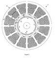
- FIG. 2 is a cut-away end view of a PM dynamoelectric machine 28 according to another possible embodiment of the invention.
- a generally star-shaped stator shunt and tooth structure 30 comprises integral saturable ferromagnetic shunts 32 and stator teeth 34.
- Each shunt 32 is a saturable ferromagnetic region between adjacent stator teeth 34 of the stator shunt and tooth structure.
- Each shunt 32 has an associated saturation control coil 24.
- the star-shaped shunt and tooth structure 30 may conveniently comprise a ferromagnetic stamping.
- the shunt and tooth structure 30 mounts in a stator yoke 36 to form a complete stator assembly 38. It is identical in function and operation to the embodiment of the invention hereinbefore described in connection with Figure 1 .
- FIG. 3 is a schematic representation of the control coils 24 with their respective shunt magnetic fluxes ⁇ sh , represented by arrows 40, with control current I c provided by a control current source 42. Dots 44 represent the phasing of the control coils 24.
- This connection may comprise a serial connection of the control coils 24 with adjacent control coils 24 in phase opposition, such as a first side of each control coil 24, represented by its respective dot 44, connecting to a first side of a preceding adjacent control coil 24 in the series connection and a second side of each control coil 24 opposite the first side connecting to second side of the following adjacent control coil 24 in the series connection.
- This connection is only possible with the use of direct current DC for the source 42 of control current I c .
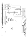
- FIG 4 is a high-level schematic representation of an electrical power generating system 46 according to a possible embodiment of the invention comprising a prime mover 48, such as an aeronautical gas turbine engine, and the PM dynamoelectric machine with multiple magnetically saturable ferromagnetic shunts, such as the PM dynamoelectric machine 2 as shown in Figure 1 or the PM dynamoelectric machine 28 as shown in Figure 2 .
- the prime mover 48 drives the machine 2, 28 by way of its drive shaft 4.
- An auxiliary power source 50 supplies power to a control current regulator 52 by way of an auxiliary power bus 54.
- the auxiliary power source 50 may be AC or DC. It preferably comprises a multiphase AC auxiliary PM dynamoelectric machine 56 driven by the drive shaft 4 and a multiphase AC rectifier 58 that receives multiphase AC power from the auxiliary machine 56 on a multiphase AC auxiliary power bus 60 and converts it to DC power on the auxiliary power bus 54.
- the auxiliary power source 50 may be a separately powered source or a battery.
- the auxiliary machine 56 may be any prior art PM machine.
- the control current regulator 52 preferably comprises an H-bridge circuit.
- the regulator 52 supplies control current I c to multiple control coils 24 in the machine 2, 28 by way of a control current supply bus 62.
- a control current sensor 64 monitors the level of control current passing through the control current supply bus 62 and generates a corresponding control current feedback signal representative of its level on a control current feedback signal line 66.
- a multiphase AC main power rectifier 68 receives multiphase AC power from the stator coils 20 of the machine 2, 28 on a multiphase AC main power bus 70 and converts it to DC main power on a DC main power bus 72 for supply to a DC load 74.
- a main power voltage sensor 76 monitors the level of voltage on the DC main power bus 72 and generates a corresponding main power voltage feedback signal representative of its level on a main power voltage feedback signal line 78.
- a voltage signal comparator 80 receives a main power voltage reference signal on a voltage reference line 82 and compares it to the main power voltage feedback signal on the main power voltage signal line 78 to generate a voltage difference signal representative of the difference between them on a voltage difference signal line 84.
- a main power voltage feedback proportional-plus-integral (PI) controller 86 receives the voltage difference signal on the voltage difference signal line 84 and converts it to a stable control current reference signal on a control current reference signal line 88.
- PI proportional-plus-integral
- a current signal comparator 90 compares the control current reference signal on the control current reference signal line 88 with the control current feedback signal on the control current feedback signal line 66 to generate a current difference signal on a current difference signal line 92.
- a control current feedback PI controller 94 receives the current difference signal on the current difference signal line 92 and converts it to a stable control current regulating signal on a control current regulating signal line 96.
- a pulse width modulator (PWM) circuit 98 receives the control current regulating signal on a control current regulating signal line 96 and generates corresponding PWM control signals on a PWM control signal bus 100.
- a gate drive circuit 102 receives the PWM control signals on a PWM control signal bus 100 and generates corresponding gate drive signals on a gate drive signal bus 104.
- the control current regulator 52 receives the gate drive signals on the gate drive signal bus 104 to produce a level of the control current I c on the control current supply bus 62 responsive to a main power voltage feedback loop 106 and a control current feedback loop 108.
- Figure 5 is a graphical representation of voltage V as a function of three different angular velocities n 1 , n 2 ⁇ n 1 , and n 3 ⁇ n 2 of the PM machines 2, 28 in the electrical power generating system 46.
- Line 110 represents angular velocity n 1
- line 112 represents angular velocity n 2
- line 114 represents angular velocity n 3 .
- Line 116 represents a constant reference voltage output V const for application of respective control currents I c 1 , I c 2 and I c 3 to the control coils 24.
Landscapes
- Engineering & Computer Science (AREA)
- Power Engineering (AREA)
- Control Of Eletrric Generators (AREA)
- Permanent Magnet Type Synchronous Machine (AREA)
Abstract
Description
- The invention relates to permanent magnet (PM) electric generators, and more particularly to PM electric generators with variable magnetic flux excitation.
- Electrical power generation systems powered by variable speed prime movers that require highly regulated electrical output, such as electrical power generation systems used for aeronautical applications, generally use a wound field synchronous machine (WFSM) that serves as an electrical generator. This is because it is easy to adjust rotor current to regulate electrical output of a WFSM. In aeronautical applications, the prime mover is often a gas turbine engine that has a normal angular velocity that exceeds 20,000 revolutions per minute. Due to the angular velocity limitations of the WFSM, such electrical power generation systems generally require a reduction gearbox between the prime mover and the WFSM. This increases weight, cost and complexity of the electrical power generation systems.
- Electrical power generation systems may alternatively employ an electrical machine of the permanent magnet (PM) type as an electrical generator. Such a PM machine is capable of much higher angular velocity than a WFSM of similar output and therefore it is capable of direct coupling to the prime mover, thereby eliminating the reduction gearbox. This results in reduced weight, cost and complexity of an electrical power generation system. However, traditional PM machines have no convenient means to alter magnetic flux for regulating their output.
- An electrical power generation system may alternatively use a regulated PM machine that has a field excitation control winding. These so-called hybrid electric machines with PMs and an additional field excitation winding for direct flux control may be a better choice for industrial motor drives and generators. However, most such hybrid electric machines have relatively complex designs with resulting increases in size, weight and expense.
- The invention generally comprises a permanent magnet (PM) electric generator with directly controllable field excitation control comprising: a drive shaft; a PM rotor assembly with multiple PMs arranged around an outer axial periphery of the rotor assembly; a stator assembly comprising a ferromagnetic stator yoke, multiple ferromagnetic stator teeth mounted to the stator yoke with distal ends proximate the outer axial periphery of the rotor assembly separated by an air gap and multiple stator coils mounted between the stator teeth; multiple saturable ferromagnetic shunts, each shunt coupling adjacent distal ends of the stator teeth to shunt air gap magnetic flux Φ g generated by the PMs across the air gap through the distal ends of the stator teeth; and multiple saturation control coils, each saturation control coil being wrapped about a saturable region of an associated one of the shunts; wherein application of a control current Ic to the control coils at least partially magnetically saturates the shunts to reduce shunting of air gap magnetic flux Φ g , thereby increasing magnetic flux linkage Ψ M between the PMs and the stator coils and increasing generated electromagnetic force (EMF) at lower levels of rotor assembly angular velocity.
-
-
Figure 1 is a cut-away end view of a permanent magnet (PM) dynamoelectric machine according to one possible embodiment of the invention. -
Figure 2 is a cut-away end view of a PM dynamoelectric machine according to another possible embodiment of the invention. -
Figure 3 is a schematic representation of control coils for the PM dynamoelectric machines ofFigures 1 and2 that shows their respective shunt magnetic fluxes Φ sh and control current Ic provided by a control current source. -
Figure 4 is a high-level schematic representation of an electrical power generating system according to a possible embodiment of the invention. -
Figure 5 is a graphical representation of voltage as a function of three different angular velocities of the PM machines ofFigures 1 and2 . -
Figure 1 is a cut-away end view of a permanent magnet (PM)dynamoelectric machine 2 according to one possible embodiment of the invention. Themachine 2 has adrive shaft 4 that couples to aPM rotor assembly 6. ThePM rotor assembly 6 comprisesmultiple PMs 8 mounted about its outerannular periphery 10. By way of example only,Figure 1 shows thePM rotor assembly 6 with fourPMs 8. - A multiple
pole stator assembly 12, typically of the multiphase alternating current (AC) type, circumscribes therotor assembly 6. Thestator assembly 12 has multipleferromagnetic stator teeth 14 coupled to aferromagnetic stator yoke 16, onestator tooth 14 for each of the poles of thestator assembly 12. Adistal end 18 of eachstator tooth 14 is proximate the outerannular periphery 10 of therotor assembly 6. Thestator assembly 12 also hasmultiple stator coils 20 mounted between thestator teeth 14. By way of example only,Figure 1 shows thestator coils 20 arranged in a multiphase AC two-layer wrap. - The hereinbefore-identified components of the
machine 2 describe a typical PM dynamoelectric machine. In operation as an electric generator, a prime mover (not shown) coupled to thedrive shaft 4 rotates therotor assembly 6. With a magnetic flux linkage Ψ M between thePMs 8 and thestator coils 20, the rotating magnetic field that thePMs 8 generate causes magnetic excitation flux to flow through thestator coils 20, thereby generating multiphase electrical power in thestator coils 20. Fixed excitation flux provided by thePMs 8 in therotor assembly 6 limits the use of themachine 2, since electromotive force (EMF) that themachine 2 generates is proportional to the rate of change of magnetic flux passing through thestator coils 20 and this rate of change is proportional to the angular velocity of therotor assembly 6. Thus, for any variation in angular velocity of the prime mover, the EMF of themachine 2 will vary as well. - It is possible to regulate the EMF of the
machine 2 over a range of angular velocities of therotor assembly 6 by means of proportionally changing the magnetic flux linkage Ψ M . Themachine 2 is able to regulate the magnetic flux linkage Ψ M directly by means of multiple magnetically saturableferromagnetic shunts 22, each generally wedge-shaped shunt 22 being inserted and mounted between the correspondingdistal ends 18 ofadjacent stator teeth 14. Eachshunt 22 has an associatedsaturation control coil 24. Thecontrol coils 24 may connect to each other in a series or parallel configuration, although series is preferred, and may receive DC or AC control current for Ic saturation control. - The
shunts 22 preferably comprise a laminated ferromagnetic alloy or sintered magnetic powder construction. Theshunts 22 with their associatedcontrol coils 24 preferably are insertable between thestator teeth 14 of thestator assembly 12 proximate theirdistal ends 18. Thecontrol coils 24 may comprise coils of round, rectangular or foil conductors. - The
shunts 22 behave as magnetic flux shunts or diverters for magnetic flux that therotor assembly 6 generates. When the magnetic reluctance of theshunts 22 is low, such as with no control current passing through their associatedcontrol coils 24, theshunts 22 shunt most of an air gap magnetic flux Φ g generated by thePMs 8 that passes across anair gap 26 between the outeraxial periphery 10 of therotor assembly 6 and thedistal ends 18 of thestator teeth 14. That is, a shunting magnetic flux closely approximates air gap magnetic flux [Φ sh ≈Φ g ] with no control current passing through thecontrol coils 24. As a result, the magnetic flux linkage Ψ M between thePMs 8 and thestator coils 20 is low and the corresponding EMF generated by themachine 2 is low for a given angular velocity of therotor assembly 6, since it is proportional to the magnetic flux linkage Ψ M . - When the control current Ic is greater than zero, the
shunts 22 partially saturate, their magnetic permeability decreases, their reluctance increases and therefore they only shunt a portion of the air gap flux Φ g so that Φ sh < Φ g . The magnetic flux linkage Ψ M between thePMs 8 and thestator coils 20 increases. Likewise, for a given angular velocity of therotor assembly 6, the EMF induced in thestator coils 20 increases as well. Further increase in the control current Ic reduces the reluctance of theshunts 22 still further and their relative magnetic permeability approaches unity. Fullysaturated shunts 22 behave as free space so that almost the entire air gap magnetic flux Φ g generated by thePMs 8 penetrates through thestator teeth 14 andstator yoke 16 so that the magnetic flux linkage Ψ M approximates the air gap flux Φ g . This generates maximum EMF in thestator coils 20 for a given angular velocity of therotor assembly 6. Thus, for any given angular velocity of therotor assembly 6, there is a value of control current Ic that will maintain a constant desired value of EMF from themachine 2. -
Figure 2 is a cut-away end view of a PMdynamoelectric machine 28 according to another possible embodiment of the invention. In this embodiment, a generally star-shaped stator shunt andtooth structure 30 comprises integral saturableferromagnetic shunts 32 andstator teeth 34. Eachshunt 32 is a saturable ferromagnetic region betweenadjacent stator teeth 34 of the stator shunt and tooth structure. Eachshunt 32 has an associatedsaturation control coil 24. The star-shaped shunt andtooth structure 30 may conveniently comprise a ferromagnetic stamping. The shunt andtooth structure 30 mounts in astator yoke 36 to form acomplete stator assembly 38. It is identical in function and operation to the embodiment of the invention hereinbefore described in connection withFigure 1 . - The magnetic flux that the
PMs 8 generate may induce some AC voltage in thecontrol coils 24. If this is objectionable, a special connection of thecontrol coils 24 will cancel this effect. Such a special connection means connecting adjacent control coils 24 to arrange their respective shunt magnetic fluxes Φ sh in opposition.Figure 3 is a schematic representation of the control coils 24 with their respective shunt magnetic fluxes Φ sh , represented byarrows 40, with control current Ic provided by a controlcurrent source 42.Dots 44 represent the phasing of the control coils 24. This connection may comprise a serial connection of the control coils 24 with adjacent control coils 24 in phase opposition, such as a first side of eachcontrol coil 24, represented by itsrespective dot 44, connecting to a first side of a precedingadjacent control coil 24 in the series connection and a second side of eachcontrol coil 24 opposite the first side connecting to second side of the followingadjacent control coil 24 in the series connection. This connection is only possible with the use of direct current DC for thesource 42 of control current Ic . -
Figure 4 is a high-level schematic representation of an electricalpower generating system 46 according to a possible embodiment of the invention comprising aprime mover 48, such as an aeronautical gas turbine engine, and the PM dynamoelectric machine with multiple magnetically saturable ferromagnetic shunts, such as the PMdynamoelectric machine 2 as shown inFigure 1 or the PMdynamoelectric machine 28 as shown inFigure 2 . Theprime mover 48 drives themachine drive shaft 4. Anauxiliary power source 50 supplies power to a controlcurrent regulator 52 by way of anauxiliary power bus 54. - The
auxiliary power source 50 may be AC or DC. It preferably comprises a multiphase AC auxiliary PMdynamoelectric machine 56 driven by thedrive shaft 4 and amultiphase AC rectifier 58 that receives multiphase AC power from theauxiliary machine 56 on a multiphase ACauxiliary power bus 60 and converts it to DC power on theauxiliary power bus 54. Alternatively, theauxiliary power source 50 may be a separately powered source or a battery. Theauxiliary machine 56 may be any prior art PM machine. - The control
current regulator 52 preferably comprises an H-bridge circuit. Theregulator 52 supplies control current Ic to multiple control coils 24 in themachine current supply bus 62. A controlcurrent sensor 64 monitors the level of control current passing through the controlcurrent supply bus 62 and generates a corresponding control current feedback signal representative of its level on a control currentfeedback signal line 66. - A multiphase AC
main power rectifier 68 receives multiphase AC power from the stator coils 20 of themachine main power bus 70 and converts it to DC main power on a DCmain power bus 72 for supply to aDC load 74. A mainpower voltage sensor 76 monitors the level of voltage on the DCmain power bus 72 and generates a corresponding main power voltage feedback signal representative of its level on a main power voltagefeedback signal line 78. - A
voltage signal comparator 80 receives a main power voltage reference signal on avoltage reference line 82 and compares it to the main power voltage feedback signal on the main powervoltage signal line 78 to generate a voltage difference signal representative of the difference between them on a voltagedifference signal line 84. A main power voltage feedback proportional-plus-integral (PI)controller 86 receives the voltage difference signal on the voltagedifference signal line 84 and converts it to a stable control current reference signal on a control currentreference signal line 88. - A
current signal comparator 90 compares the control current reference signal on the control currentreference signal line 88 with the control current feedback signal on the control currentfeedback signal line 66 to generate a current difference signal on a currentdifference signal line 92. A control currentfeedback PI controller 94 receives the current difference signal on the currentdifference signal line 92 and converts it to a stable control current regulating signal on a control currentregulating signal line 96. - A pulse width modulator (PWM)
circuit 98 receives the control current regulating signal on a control currentregulating signal line 96 and generates corresponding PWM control signals on a PWMcontrol signal bus 100. Agate drive circuit 102 receives the PWM control signals on a PWMcontrol signal bus 100 and generates corresponding gate drive signals on a gatedrive signal bus 104. - The control
current regulator 52 receives the gate drive signals on the gatedrive signal bus 104 to produce a level of the control current Ic on the controlcurrent supply bus 62 responsive to a main powervoltage feedback loop 106 and a controlcurrent feedback loop 108. -
Figure 5 is a graphical representation of voltage V as a function of three different angular velocities n 1, n 2 < n 1, and n 3 < n 2 of thePM machines power generating system 46.Line 110 represents angular velocity n 1,line 112 represents angular velocity n 2 andline 114 represents angular velocity n 3.Line 116 represents a constant reference voltage output Vconst for application of respective control currents I c1, I c2 and I c3 to the control coils 24. - The described embodiments of the invention are only some illustrative implementations of the invention wherein changes and substitutions of the various parts and arrangement thereof may be made within the scope of the invention, which is set forth in the attached claims.
Claims (15)
- A permanent magnet electric generator (2,28) with directly controllable field excitation control, comprising:a drive shaft (4);a permanent magnet rotor assembly (6) with multiple permanent magnets (8) arranged around an outer annular periphery of the rotor assembly;a stator assembly (12) comprising a ferromagnetic stator yoke (16), multiple ferromagnetic stator teeth (14,34) mounted to the stator yoke with distal ends proximate the outer annular periphery of the rotor assembly and separated therefrom by an air gap, and multiple stator coils (20) mounted between the stator teeth;multiple saturable ferromagnetic shunts (22,32), each shunt coupling adjacent distal ends of the stator teeth to shunt air gap magnetic flux Φ g generated by the permanent magnets across the air gap through the distal ends of the stator teeth; andmultiple saturation control coils (24), each saturation control coil being wrapped about a saturable region of an associated one of the shunts;wherein application of a control current Ic to the control coils at least partially magnetically saturates the shunts to reduce shunting of air gap magnetic fluxΦ g , thereby increasing magnetic flux linkage Ψ M between the permanent magnets and the stator coils and increasing generated electromagnetic force (EMF) at lower levels of rotor assembly angular velocity.
- The generator of Claim 1, wherein each shunt comprises a generally wedge-shaped shunt (22) that mounts between the distal ends of adjacent ones of the stator teeth.
- The generator of Claim 1 or 2, wherein each shunt has a laminated ferromagnetic alloy construction; or wherein each shunt comprises a sintered magnetic powder construction.
- The generator of Claim 1, 2 or 3 further comprising a generally star-shaped stator tooth and shunt structure (30) mounted within the stator yoke that forms the stator teeth and shunts; the stator tooth and shunt structure preferably comprising a ferromagnetic stamping.
- The generator of Claim 4, wherein each shunt is an integral saturable ferromagnetic region between stator teeth of the stator tooth and shunt structure.
- The generator of any preceding Claim, wherein the control coils attach to each other in series.
- The generator of Claim 6, wherein the control current Ic is alternating current (AC); or wherein the control current Ic is direct current (DC).
- The generator of any preceding Claim, wherein adjacent ones of the control coils connect to each other to arrange their respective shunting magnetic fluxes Φ sh in opposition.
- The generator of Claim 8, wherein a first side of each control coil connects to a first side of a preceding adjacent control coil in the series connection and a second side of each control coil opposite the first side connects to a second side of the following adjacent control coil in the series connection.
- A permanent magnet electric generator system with directly controllable field excitation control comprising:a prime mover (48);a main permanent magnet generator (2,28) as claimed in any preceding claim coupled to the prime mover;a main power rectifier system (68) for converting multiphase alternating current (AC) that the main permanent magnet stator coils generate to direct current (DC) main power on a DC power bus that feeds a DC load;an auxiliary power source (50);a control current regulator (52) that regulates current from the auxiliary power source to produce control current Ic for the permanent magnet generator control coils;a main power voltage feedback loop (106) that compares voltage on the DC power bus to a reference voltage and generates a reference control current signal representative of the difference; anda control current feedback loop (108) that compares the control current to the control current reference signal and generates a control current regulating signal representative of the difference that changes the control current produced by the control current regulator.
- The system of Claim 10, wherein the auxiliary power source (50) comprises a multiphase AC auxiliary permanent magnet generator driven by the prime mover (48) and a multiphase AC rectifier (58) that converts AC power generated by the auxiliary permanent magnet generator to DC power.
- The system of Claim 10 or 11, wherein the control current regulator (52) comprises an H-bridge circuit.
- The system of Claim 12, further comprising a pulse width modulator (PWM) circuit (98) that receives the control current regulating signal and generates corresponding PWM control signals; and preferably further comprising a gate drive circuit (102) that receives the PWM control signals and generates corresponding gate drive signals that drive the H-bridge circuit.
- The system of Claim 10, 11, 12 or 13, wherein the main power voltage feedback loop (106) comprises:a main power voltage sensor (76) that monitors the level of voltage on the DC main power bus and generates a corresponding main power voltage feedback signal representative of its level;a voltage signal comparator (80) that receives a main power voltage reference signal and compares it to the main power voltage feedback signal to generate a voltage difference signal representative of the difference between them; anda main power voltage feedback proportional-plus-integral (PI) controller (86) that receives the voltage difference signal and converts it to the control current reference signal.
- The system of any of Claims 10 to 14, wherein the control current feedback loop comprises:a control current sensor (64) that monitors the level of control current Ic and generates a corresponding control current feedback signal representative of its level;a current signal comparator (90) that compares the control current reference signal with the control current feedback signal to generate a current difference signal; anda control current feedback PI controller (94) that receives the current difference signal converts it to the control current regulating signal.
Applications Claiming Priority (1)
| Application Number | Priority Date | Filing Date | Title |
|---|---|---|---|
| US12/061,309 US7859231B2 (en) | 2008-04-02 | 2008-04-02 | Permanent magnet electric generator with variable magnet flux excitation |
Publications (3)
| Publication Number | Publication Date |
|---|---|
| EP2107664A2 true EP2107664A2 (en) | 2009-10-07 |
| EP2107664A3 EP2107664A3 (en) | 2012-10-24 |
| EP2107664B1 EP2107664B1 (en) | 2014-05-21 |
Family
ID=40848648
Family Applications (1)
| Application Number | Title | Priority Date | Filing Date |
|---|---|---|---|
| EP09250814.2A Active EP2107664B1 (en) | 2008-04-02 | 2009-03-24 | Permanent magnet electric generator with variable magnetic flux excitation |
Country Status (2)
| Country | Link |
|---|---|
| US (1) | US7859231B2 (en) |
| EP (1) | EP2107664B1 (en) |
Cited By (2)
| Publication number | Priority date | Publication date | Assignee | Title |
|---|---|---|---|---|
| WO2013053024A2 (en) | 2011-10-12 | 2013-04-18 | Denev Svetogor Svetoslavov | Generator |
| EP3316459A1 (en) * | 2016-10-26 | 2018-05-02 | Hamilton Sundstrand Corporation | Electric motors |
Families Citing this family (19)
| Publication number | Priority date | Publication date | Assignee | Title |
|---|---|---|---|---|
| US8358111B2 (en) | 2009-12-03 | 2013-01-22 | Hamilton Sundstrand Corporation | Architecture for dual source electric power generating system |
| RU2459395C1 (en) * | 2011-04-06 | 2012-08-20 | Федеральное государственное бюджетное образовательное учреждение высшего профессионального образования "Национальный исследовательский Томский политехнический университет" | Linear induction accelerator |
| EP3090838B1 (en) | 2011-05-19 | 2020-06-17 | Black & Decker Inc. | Power tool with force sensing electronic clutch |
| US8823331B2 (en) | 2011-09-15 | 2014-09-02 | Lovejoy Controls Corporation | Permanent magnet generator |
| US8390164B1 (en) | 2011-09-20 | 2013-03-05 | Hamilton Sundstrand Corporation | Method of fabrication of permanent magnet machines with magnetic flux regulation |
| US8922154B2 (en) | 2012-01-13 | 2014-12-30 | Hamilton Sundstrand Corporation | Brushless starter-generator assembly and method to control magnetic flux excitation |
| US9343931B2 (en) * | 2012-04-06 | 2016-05-17 | David Deak | Electrical generator with rotational gaussian surface magnet and stationary coil |
| US8598725B1 (en) | 2012-06-11 | 2013-12-03 | United Technologies Corporation | Utilizing flux controllable PM electric machines for wind turbine applications |
| US10787967B2 (en) | 2014-08-12 | 2020-09-29 | Hamilton Sundstrand Corporation | Starter-generator modules for gas turbine engines |
| US9573539B2 (en) * | 2014-08-18 | 2017-02-21 | Hamilton Sundstrand Corporation | Electric system architecture for more-electric engine accessories |
| CN104626954A (en) * | 2014-12-12 | 2015-05-20 | 广西科技大学 | Electric car asynchronous motor control system |
| US9705440B2 (en) | 2015-07-16 | 2017-07-11 | Hamilton Sundstrand Corporation | Fault tolerant electric power generating system |
| US10355568B2 (en) | 2015-10-27 | 2019-07-16 | Hamilton Sundstrand Corporation | Flux control of permanent magnet electric machine |
| US10483891B2 (en) * | 2017-01-06 | 2019-11-19 | Hamilton Sundstrand Corporation | Double stator permanent magnet machine with magnetic flux regulation |
| US20180254688A1 (en) | 2017-03-06 | 2018-09-06 | Hamilton Sundstrand Corporation | Wound-rotor synchronous machine with permanent magnets |
| CN108631463B (en) * | 2017-03-16 | 2024-03-05 | 上海艾高实业有限公司 | Polygonal excitation permanent magnet motor |
| US10608501B2 (en) | 2017-05-24 | 2020-03-31 | Black & Decker Inc. | Variable-speed input unit having segmented pads for a power tool |
| US10944302B2 (en) | 2018-04-09 | 2021-03-09 | Williams International Co., L.L.C. | Permanent-magnet generator incorporating a variable-reluctance stator system |
| US12009772B2 (en) * | 2021-12-07 | 2024-06-11 | Hamilton Sundstrand Corporation | Parallel excitation of motor start function for three stage synchronous generator |
Citations (1)
| Publication number | Priority date | Publication date | Assignee | Title |
|---|---|---|---|---|
| JP2007028881A (en) | 2005-06-14 | 2007-02-01 | Nissan Motor Co Ltd | Rotating electric machine |
Family Cites Families (10)
| Publication number | Priority date | Publication date | Assignee | Title |
|---|---|---|---|---|
| US5281905A (en) * | 1989-12-14 | 1994-01-25 | Sundstrand Corporation | Induction machine based hybrid aircraft engine starting/generating power system |
| TR199701076T1 (en) * | 1995-03-31 | 1998-02-21 | Ecoair Corp. | Karma alternat�r. |
| US6586914B2 (en) * | 2001-11-19 | 2003-07-01 | General Electric Company | Wound field synchronous machine control system and method |
| JP2005073450A (en) * | 2003-08-27 | 2005-03-17 | Matsushita Electric Ind Co Ltd | Motor generator |
| US7309974B2 (en) * | 2005-11-08 | 2007-12-18 | Honeywell International, Inc. | System and method for AC power generation from a reluctance machine |
| US7288923B1 (en) * | 2006-04-21 | 2007-10-30 | Pratt & Whitney Canada Corp. | Voltage-limited electric machine |
| JP4894417B2 (en) * | 2006-08-30 | 2012-03-14 | 国産電機株式会社 | Power generator |
| US7439713B2 (en) * | 2006-09-20 | 2008-10-21 | Pratt & Whitney Canada Corp. | Modulation control of power generation system |
| DE602006005673D1 (en) * | 2006-09-29 | 2009-04-23 | Abb Oy | Procedure in conjunction with a frequency converter |
| US7777384B2 (en) * | 2008-04-02 | 2010-08-17 | Hamilton Sundstrand Corporation | Permanent magnet dynamoelectric machine with variable magnetic flux excitation |
-
2008
- 2008-04-02 US US12/061,309 patent/US7859231B2/en active Active
-
2009
- 2009-03-24 EP EP09250814.2A patent/EP2107664B1/en active Active
Patent Citations (1)
| Publication number | Priority date | Publication date | Assignee | Title |
|---|---|---|---|---|
| JP2007028881A (en) | 2005-06-14 | 2007-02-01 | Nissan Motor Co Ltd | Rotating electric machine |
Cited By (3)
| Publication number | Priority date | Publication date | Assignee | Title |
|---|---|---|---|---|
| WO2013053024A2 (en) | 2011-10-12 | 2013-04-18 | Denev Svetogor Svetoslavov | Generator |
| EP3316459A1 (en) * | 2016-10-26 | 2018-05-02 | Hamilton Sundstrand Corporation | Electric motors |
| US10505411B2 (en) * | 2016-10-26 | 2019-12-10 | Hamilton Sundstrand Corporation | Electric motors |
Also Published As
| Publication number | Publication date |
|---|---|
| EP2107664B1 (en) | 2014-05-21 |
| EP2107664A3 (en) | 2012-10-24 |
| US20090251112A1 (en) | 2009-10-08 |
| US7859231B2 (en) | 2010-12-28 |
Similar Documents
| Publication | Publication Date | Title |
|---|---|---|
| EP2107664B1 (en) | Permanent magnet electric generator with variable magnetic flux excitation | |
| US7777384B2 (en) | Permanent magnet dynamoelectric machine with variable magnetic flux excitation | |
| EP2782226B1 (en) | Flux controlled PM electric machine rotor | |
| EP3346590B1 (en) | Double stator permanent magnet machine with magnetic flux regulation | |
| EP3376650A1 (en) | Permanent magnet starter-generator with magnetic flux regulation | |
| US9231504B2 (en) | Electrical control system | |
| JP5216686B2 (en) | Permanent magnet generator | |
| US7852049B2 (en) | Dual channel power generation system | |
| EP2007003B1 (en) | Generating system with a regulated permanent magnet machine and an active rectifier | |
| US7521906B2 (en) | Generating system with a regulated permanent magnet machine | |
| US8148867B2 (en) | Permanent magnet brushless machine with magnetic flux regulation | |
| WO2006047524A1 (en) | Ac generator with independently controlled field rotational speed | |
| US10541634B2 (en) | Generator arrangements and methods of controlling generator arrangements | |
| JP6244598B2 (en) | Wind turbine generator having variable magnetic flux field type synchronous generator | |
| RU2637767C2 (en) | Method of stabilization of output voltage of magnetoelectric generator | |
| US5130590A (en) | Brushless generator regulated by second rotor | |
| CN104638860B (en) | Harmonic wave self-excitation combined magnetic pole AC exciter | |
| JP3811181B2 (en) | Generator | |
| JP3843355B2 (en) | Power generator | |
| JP2008278716A (en) | Wind power generator | |
| CN113364238A (en) | Parallel magnetic circuit hybrid excitation brushless motor | |
| JPH0879912A (en) | Hybrid driver | |
| JP2003230298A (en) | Alternator | |
| JPH0461586B2 (en) |
Legal Events
| Date | Code | Title | Description |
|---|---|---|---|
| PUAI | Public reference made under article 153(3) epc to a published international application that has entered the european phase |
Free format text: ORIGINAL CODE: 0009012 |
|
| AK | Designated contracting states |
Kind code of ref document: A2 Designated state(s): AT BE BG CH CY CZ DE DK EE ES FI FR GB GR HR HU IE IS IT LI LT LU LV MC MK MT NL NO PL PT RO SE SI SK TR |
|
| AX | Request for extension of the european patent |
Extension state: AL BA RS |
|
| REG | Reference to a national code |
Ref country code: DE Ref legal event code: R079 Ref document number: 602009024231 Country of ref document: DE Free format text: PREVIOUS MAIN CLASS: H02K0001160000 Ipc: H02K0003493000 |
|
| PUAL | Search report despatched |
Free format text: ORIGINAL CODE: 0009013 |
|
| AK | Designated contracting states |
Kind code of ref document: A3 Designated state(s): AT BE BG CH CY CZ DE DK EE ES FI FR GB GR HR HU IE IS IT LI LT LU LV MC MK MT NL NO PL PT RO SE SI SK TR |
|
| AX | Request for extension of the european patent |
Extension state: AL BA RS |
|
| RIC1 | Information provided on ipc code assigned before grant |
Ipc: H02K 21/04 20060101ALI20120914BHEP Ipc: H02P 9/34 20060101ALI20120914BHEP Ipc: H02K 3/493 20060101AFI20120914BHEP Ipc: H02K 3/20 20060101ALI20120914BHEP |
|
| 17P | Request for examination filed |
Effective date: 20130423 |
|
| AKX | Designation fees paid |
Designated state(s): DE FR GB |
|
| GRAP | Despatch of communication of intention to grant a patent |
Free format text: ORIGINAL CODE: EPIDOSNIGR1 |
|
| INTG | Intention to grant announced |
Effective date: 20131209 |
|
| GRAS | Grant fee paid |
Free format text: ORIGINAL CODE: EPIDOSNIGR3 |
|
| GRAA | (expected) grant |
Free format text: ORIGINAL CODE: 0009210 |
|
| AK | Designated contracting states |
Kind code of ref document: B1 Designated state(s): DE FR GB |
|
| REG | Reference to a national code |
Ref country code: GB Ref legal event code: FG4D |
|
| REG | Reference to a national code |
Ref country code: DE Ref legal event code: R096 Ref document number: 602009024231 Country of ref document: DE Effective date: 20140710 |
|
| REG | Reference to a national code |
Ref country code: DE Ref legal event code: R097 Ref document number: 602009024231 Country of ref document: DE |
|
| PLBE | No opposition filed within time limit |
Free format text: ORIGINAL CODE: 0009261 |
|
| STAA | Information on the status of an ep patent application or granted ep patent |
Free format text: STATUS: NO OPPOSITION FILED WITHIN TIME LIMIT |
|
| 26N | No opposition filed |
Effective date: 20150224 |
|
| REG | Reference to a national code |
Ref country code: DE Ref legal event code: R097 Ref document number: 602009024231 Country of ref document: DE Effective date: 20150224 |
|
| REG | Reference to a national code |
Ref country code: FR Ref legal event code: PLFP Year of fee payment: 8 |
|
| REG | Reference to a national code |
Ref country code: FR Ref legal event code: PLFP Year of fee payment: 9 |
|
| REG | Reference to a national code |
Ref country code: DE Ref legal event code: R082 Ref document number: 602009024231 Country of ref document: DE Representative=s name: SCHMITT-NILSON SCHRAUD WAIBEL WOHLFROM PATENTA, DE |
|
| REG | Reference to a national code |
Ref country code: FR Ref legal event code: PLFP Year of fee payment: 10 |
|
| P01 | Opt-out of the competence of the unified patent court (upc) registered |
Effective date: 20230522 |
|
| PGFP | Annual fee paid to national office [announced via postgrant information from national office to epo] |
Ref country code: DE Payment date: 20250218 Year of fee payment: 17 |
|
| PGFP | Annual fee paid to national office [announced via postgrant information from national office to epo] |
Ref country code: FR Payment date: 20250219 Year of fee payment: 17 |
|
| PGFP | Annual fee paid to national office [announced via postgrant information from national office to epo] |
Ref country code: GB Payment date: 20250221 Year of fee payment: 17 |