EP2107643A2 - Antioxidant joint compound and method for forming an electrical connection - Google Patents
Antioxidant joint compound and method for forming an electrical connection Download PDFInfo
- Publication number
- EP2107643A2 EP2107643A2 EP09250829A EP09250829A EP2107643A2 EP 2107643 A2 EP2107643 A2 EP 2107643A2 EP 09250829 A EP09250829 A EP 09250829A EP 09250829 A EP09250829 A EP 09250829A EP 2107643 A2 EP2107643 A2 EP 2107643A2
- Authority
- EP
- European Patent Office
- Prior art keywords
- antioxidant
- stainless steel
- components
- joint compound
- steel grit
- Prior art date
- Legal status (The legal status is an assumption and is not a legal conclusion. Google has not performed a legal analysis and makes no representation as to the accuracy of the status listed.)
- Granted
Links
Images

Classifications
-
- H—ELECTRICITY
- H01—ELECTRIC ELEMENTS
- H01R—ELECTRICALLY-CONDUCTIVE CONNECTIONS; STRUCTURAL ASSOCIATIONS OF A PLURALITY OF MUTUALLY-INSULATED ELECTRICAL CONNECTING ELEMENTS; COUPLING DEVICES; CURRENT COLLECTORS
- H01R4/00—Electrically-conductive connections between two or more conductive members in direct contact, i.e. touching one another; Means for effecting or maintaining such contact; Electrically-conductive connections having two or more spaced connecting locations for conductors and using contact members penetrating insulation
- H01R4/10—Electrically-conductive connections between two or more conductive members in direct contact, i.e. touching one another; Means for effecting or maintaining such contact; Electrically-conductive connections having two or more spaced connecting locations for conductors and using contact members penetrating insulation effected solely by twisting, wrapping, bending, crimping, or other permanent deformation
- H01R4/18—Electrically-conductive connections between two or more conductive members in direct contact, i.e. touching one another; Means for effecting or maintaining such contact; Electrically-conductive connections having two or more spaced connecting locations for conductors and using contact members penetrating insulation effected solely by twisting, wrapping, bending, crimping, or other permanent deformation by crimping
- H01R4/188—Electrically-conductive connections between two or more conductive members in direct contact, i.e. touching one another; Means for effecting or maintaining such contact; Electrically-conductive connections having two or more spaced connecting locations for conductors and using contact members penetrating insulation effected solely by twisting, wrapping, bending, crimping, or other permanent deformation by crimping having an uneven wire-receiving surface to improve the contact
-
- H—ELECTRICITY
- H01—ELECTRIC ELEMENTS
- H01R—ELECTRICALLY-CONDUCTIVE CONNECTIONS; STRUCTURAL ASSOCIATIONS OF A PLURALITY OF MUTUALLY-INSULATED ELECTRICAL CONNECTING ELEMENTS; COUPLING DEVICES; CURRENT COLLECTORS
- H01R4/00—Electrically-conductive connections between two or more conductive members in direct contact, i.e. touching one another; Means for effecting or maintaining such contact; Electrically-conductive connections having two or more spaced connecting locations for conductors and using contact members penetrating insulation
- H01R4/10—Electrically-conductive connections between two or more conductive members in direct contact, i.e. touching one another; Means for effecting or maintaining such contact; Electrically-conductive connections having two or more spaced connecting locations for conductors and using contact members penetrating insulation effected solely by twisting, wrapping, bending, crimping, or other permanent deformation
- H01R4/18—Electrically-conductive connections between two or more conductive members in direct contact, i.e. touching one another; Means for effecting or maintaining such contact; Electrically-conductive connections having two or more spaced connecting locations for conductors and using contact members penetrating insulation effected solely by twisting, wrapping, bending, crimping, or other permanent deformation by crimping
- H01R4/183—Electrically-conductive connections between two or more conductive members in direct contact, i.e. touching one another; Means for effecting or maintaining such contact; Electrically-conductive connections having two or more spaced connecting locations for conductors and using contact members penetrating insulation effected solely by twisting, wrapping, bending, crimping, or other permanent deformation by crimping for cylindrical elongated bodies, e.g. cables having circular cross-section
- H01R4/186—Electrically-conductive connections between two or more conductive members in direct contact, i.e. touching one another; Means for effecting or maintaining such contact; Electrically-conductive connections having two or more spaced connecting locations for conductors and using contact members penetrating insulation effected solely by twisting, wrapping, bending, crimping, or other permanent deformation by crimping for cylindrical elongated bodies, e.g. cables having circular cross-section using a body comprising a plurality of cable-accommodating recesses or bores
-
- Y—GENERAL TAGGING OF NEW TECHNOLOGICAL DEVELOPMENTS; GENERAL TAGGING OF CROSS-SECTIONAL TECHNOLOGIES SPANNING OVER SEVERAL SECTIONS OF THE IPC; TECHNICAL SUBJECTS COVERED BY FORMER USPC CROSS-REFERENCE ART COLLECTIONS [XRACs] AND DIGESTS
- Y10—TECHNICAL SUBJECTS COVERED BY FORMER USPC
- Y10T—TECHNICAL SUBJECTS COVERED BY FORMER US CLASSIFICATION
- Y10T29/00—Metal working
- Y10T29/49—Method of mechanical manufacture
- Y10T29/49002—Electrical device making
- Y10T29/49117—Conductor or circuit manufacturing
- Y10T29/49204—Contact or terminal manufacturing
- Y10T29/49208—Contact or terminal manufacturing by assembling plural parts
- Y10T29/49218—Contact or terminal manufacturing by assembling plural parts with deforming
Definitions
- the present device relates to an antioxidant joint compound for use on power and grounding wires.
- the present device relates to an antioxidant compound which improves the mechanical pullout strength of components held in electrical contact via a metal compression connector.
- thermosetting hardenable resin such as an epoxy or polyester
- Such hardening resins can be costly and often present other appreciable difficulties (e.g., exact mixing of ingredients, exothermic reaction) for those in the field preparing such connections.
- connection it is desirable to increase the rotational and/or pullout strength between the connecting components (e.g., a wire and a rod) and the connector without additional time or steps.
- connecting components e.g., a wire and a rod
- Such connections should be capable of complying with UL 467, UL 486 and IEEE 837 (2002) test standards to ensure prolonged satisfactory performance.
- a joint compound for electrical connections which comprises an antioxidant base material and a quantity of stainless steel grit mixed with the antioxidant base material to provide improved mechanical pullout strength.
- the ratio, by weight, of antioxidant to stainless steel grit is in the range of from about 30:70 to about 90:10.
- the ratio, by weight, of antioxidant to stainless steel grit is in the range of from about 40:60 to about 70:30, and more preferably the ratio, by weight, of antioxidant to stainless steel grit is about 50:50.
- the stainless steel grit is cut wire having a diameter within the range of from about 0.012 inches to about 0.125 inches.
- the grit particles have a diameter within the range of from about 0.012 inches to about 0.030 inches, and more preferably the stainless steel grit has a diameter of about 0.017 inches.
- a connection between two electrical components is formed by preparing a joint compound comprised of an antioxidant base material and stainless steel grit, providing a suitable connector for electrically coupling the components and applying the joint compound to mating surfaces of either the connector, the components to be coupled together, or both.
- the connector is then crimped to the components such that the joint compound is sandwiched between mating surfaces of the components.
- the crimping includes sufficient force to cause the stainless steel grit of the joint compound to penetrate the mating surfaces of the components.
- the penetration should be such that mechanical pullout strength of the components from the connector is improved over a similar connection made between similar components using an oil based antioxidant without stainless steel grit.
- FIG. 1 is a perspective view of an uncrimped electrical connection which may benefit from the use of an embodiment of the present joint compound
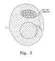
- FIG. 2 is a cross-section of a crimped electrical connection using a prior art joint compound
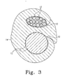
- FIG. 3 is a cross-section of a crimped electrical connection using an embodiment of the present joint compound.
- an antioxidant joint compound used for electrical connections and having stainless steel grit therein generally designated by the numeral 10.
- the compound 10 is illustrated and described herein as used with connectors designed and manufactured by the assignee of the present application, Panduit Corp. of Tinley Park, IL. Particularly, the following description and drawings refer to the use of a GCE 500-250 E-Tap or a HTCT 250-250 H-Tap connector. However, the compound 10 may be used with many other connectors in the industry with similar improved mechanical pullout strength without the sacrifice of conductivity or corrosive resistance.
- grounding connection between a grounding rod and an electrical wire strand is predominately described below and illustrated in the appended drawing figures, it is understood that other electrical components similarly connected using a joint compound would benefit by the claimed invention.
- Such connections may be power or grounding connections and may comprise wire to wire, wire to grounding rod, wire to rebar, and any other similar electrical connection configurations.
- the preferred compound 10 is an oil based material which incorporates a hard "grit like" additive 12 and is typically pre-applied to the mating surfaces of the connector prior to installation. It is preferred that the grit 12 material be conductive and be capable of penetrating any existing dirt or corrosion on the mating surfaces to create a proper conductive pathway. The particles should also be sufficiently large to create a mechanical lock between the connector and the ground rod and wire. Such mechanical lock enhances the rotational and pullout strength of the connection.
- the antioxidant compound comprised of urethane polymer of castor oil with fumed silica as a thickener and about 6.5%, by weight, copper flake for enhanced conductivity, flows into any voids during crimping to seal the connection from moisture ingress and prevent future oxidation.
- antioxidant joint compounds There are many commercially available antioxidant joint compounds on the market. Some incorporate grit like fillers such as silicon carbide where mechanical performance enhancement is desired. None, however, provide the high level of mechanical performance enhancement needed for grounding grid connections.
- the grit material 12 used for the present invention is a commercially available stainless steel cut wire shot.
- Stainless steel is a strong material and is also corrosion resistant and (mildly) electrically conductive.
- the grit 12 is available in sizes ranging from 0.012" to 0.125" diameter, and is typically used for peening, cleaning, tumbling and vibratory finishing. Preferred diameters fall within the 0.012" to 0.030" range, with 0.017" being the most preferred.
- the grit 12 is preferably cut into lengths approximately equal to the wire diameter, though variations between the diameter and cut length (e.g., 2:1 or 1:2 ratio) to suit different conditions of use would be readily understood by those skilled in the art.
- the cut ends of the wire are preferably "as cut" which are sharp and have excellent surface penetration ability.
- an oil based antioxidant such as urethane polymer of castor oil
- the antioxidant may also include a thickener, such as fumed silica, and a conductivity enhancing additive, such as copper flake, the latter being added in an amount within the range of from about 2% to 10%, by weight.
- the amount of grit 12 can vary to suit the particular use. Tests have shown that a 50/50 antioxidant to grit ratio, by weight, works well. However, ratios anywhere from 90:10 to 30:70 may have uses in the industry. The size and amount of stainless steel grit used can be varied to optimize performance for specific applications. TABLE I Mechanical Pullout Force (lbs) SAMPLE A B C D 1 322 256 1148 1456 2 201 256 1096 1225 3 269 238 1133 1527 Avg. 264 250 1126 1403 A - no antioxidant and no grit (Comparative Example) B - antioxidant, but no grit (Comparative Example). C - antioxidant with 100 mesh silicon carbide grit (50/50) (Comparative Example). D - antioxidant with 0.017" stainless steel grit (50/50).
- Examples A, B, C and D were prepared using a 3 ⁇ 4" copper bonded steel ground rod, 4/0 stranded copper wire (19 strands), and a GCE 500-250 E-Tap connector made by Panduit Corp. of Tinley Park, IL.
- the rod and wire components were bound to the properly prepared connector using a single crimp applied by a CT-2931 12 Ton Crimp Tool with PG-50 Die Index Crimp Dies, also made by Panduit.
- Examples A, B and C are comparative examples, as set forth above.
- Example B, C and D where an antioxidant was used (with or without grit material), the antioxidant was applied as a thin layer to the inner surfaces of the connector before crimping to either the wire or rod components.
- the antioxidant used was an oil based compound manufactured by Continental Products, part no. X-1432 with 10% copper flake. The grit was added to the antioxidant to produce a 50/50 mixture, by volume. No compound was applied to Example A. After applying the noted compound to Examples B, C and D, the components in all four Examples were uniformly crimped together. Using a load measuring device, the rod and wire components were then pulled apart to measure peak load (lbf) before failure (rod pullout of connector for all samples).
- Example B the use of antioxidant on the connector (Example B) caused a slight decline in the mechanical pullout strength over Example A. Such result was not unexpected, because the antioxidant is essentially an oily lubricant.
- the use of antioxidant and grit (Examples C and D) provided a 4.5 to 6 fold increase in mechanical pullout strength over Example A.
- Example D stainless steel grit
- Example D provided a nearly 25% increase in mechanical pullout strength over currently available commercial products using a silicon carbide grit.
- FIG. 1 illustrates how the grit 12 resides throughout the compound 10 as it is applied to the mating surface of the connector 14.
- the compound 10 surrounds the rod 16 and the wire 18.
- the grit 12 penetrates the mating surfaces of both the connector 14 and the rod 16.
- Examples D, E, F and G each conforms to the strict standards set forth in UL 467, UL 486 and the IEEE 837 (2002) test standards for such grounding connectors incorporating an antioxidant.
Landscapes
- Connections Effected By Soldering, Adhesion, Or Permanent Deformation (AREA)
- Lubricants (AREA)
Abstract
Description
- The present device relates to an antioxidant joint compound for use on power and grounding wires. Particularly, the present device relates to an antioxidant compound which improves the mechanical pullout strength of components held in electrical contact via a metal compression connector.
- Generally speaking, when two electrical components are connected together, it is important that the connection be strong to prevent accidental pullout of such components. This is particularly difficult to achieve with underground connections due to the fact that they are hidden underground and require an antioxidant compound to counteract against the corrosive tendencies of moist soil. Some such antioxidants are oil based and provide as much of a lubricating property as an antioxidizing property to the connection.
- Others, such as disclosed in
U.S. Patent Nos. 4,312,793 and4,214,121 to Chameski et al. , prefer to use a thermosetting hardenable resin, such as an epoxy or polyester, to solidify a connection. However, such hardening resins can be costly and often present other appreciable difficulties (e.g., exact mixing of ingredients, exothermic reaction) for those in the field preparing such connections. - Another approach has been to texturize the component surface by pre-crimping the attachment surface or knurling, for example, a grounding rod. In both cases, the use of extra tooling by those in the field only serves to unnecessarily complicate the connecting process.
- For all such connections, it is desirable to increase the rotational and/or pullout strength between the connecting components (e.g., a wire and a rod) and the connector without additional time or steps. Such connections should be capable of complying with UL 467, UL 486 and IEEE 837 (2002) test standards to ensure prolonged satisfactory performance.
- It is further desirable to penetrate any pre-existing dirt or corrosion present on the mating surfaces of the components, including the connector, to create a conductive pathway. Finally, it is also desirable to prevent moisture ingress and oxidation of the crimped connection for an extended period of time.
- These and other problems of the prior art, as well as these and other desired goals of a proper joint compound for an electrical connection, are addressed by the invention of this application.
- There is disclosed herein an improved joint compound and a method for forming an electrical connection using the joint compound which avoids the disadvantages of prior devices while affording additional structural and operating advantages.
- A joint compound for electrical connections is disclosed which comprises an antioxidant base material and a quantity of stainless steel grit mixed with the antioxidant base material to provide improved mechanical pullout strength.
- In an embodiment of the preferred joint compound the ratio, by weight, of antioxidant to stainless steel grit is in the range of from about 30:70 to about 90:10. Preferably, the ratio, by weight, of antioxidant to stainless steel grit is in the range of from about 40:60 to about 70:30, and more preferably the ratio, by weight, of antioxidant to stainless steel grit is about 50:50.
- In an embodiment of the preferred joint compound the stainless steel grit is cut wire having a diameter within the range of from about 0.012 inches to about 0.125 inches. Preferably, the grit particles have a diameter within the range of from about 0.012 inches to about 0.030 inches, and more preferably the stainless steel grit has a diameter of about 0.017 inches.
- In a preferred method, a connection between two electrical components is formed by preparing a joint compound comprised of an antioxidant base material and stainless steel grit, providing a suitable connector for electrically coupling the components and applying the joint compound to mating surfaces of either the connector, the components to be coupled together, or both. The connector is then crimped to the components such that the joint compound is sandwiched between mating surfaces of the components.
- It is an aspect of the method that the crimping includes sufficient force to cause the stainless steel grit of the joint compound to penetrate the mating surfaces of the components. The penetration should be such that mechanical pullout strength of the components from the connector is improved over a similar connection made between similar components using an oil based antioxidant without stainless steel grit.
- These and other aspects of the invention may be understood more readily from the following description and the appended drawings.
- For the purpose of facilitating an understanding of the subject matter sought to be protected, there are illustrated in the accompanying drawings embodiments thereof, from an inspection of which, when considered in connection with the following description, the subject matter sought to be protected, its construction and operation, and many of its advantages should be readily understood and appreciated.
-
FIG. 1 is a perspective view of an uncrimped electrical connection which may benefit from the use of an embodiment of the present joint compound; -
FIG. 2 is a cross-section of a crimped electrical connection using a prior art joint compound; and -
FIG. 3 is a cross-section of a crimped electrical connection using an embodiment of the present joint compound. - While this invention is susceptible of embodiments in many different forms, there is shown in the drawings and will herein be described in detail a preferred embodiment of the invention with the understanding that the present disclosure is to be considered as an exemplification of the principles of the invention and is not intended to limit the broad aspect of the invention to embodiments illustrated.
- Referring to
FIGS. 1 - 3 , there is illustrated an antioxidant joint compound used for electrical connections and having stainless steel grit therein, generally designated by thenumeral 10. Thecompound 10 is illustrated and described herein as used with connectors designed and manufactured by the assignee of the present application, Panduit Corp. of Tinley Park, IL. Particularly, the following description and drawings refer to the use of a GCE 500-250 E-Tap or a HTCT 250-250 H-Tap connector. However, thecompound 10 may be used with many other connectors in the industry with similar improved mechanical pullout strength without the sacrifice of conductivity or corrosive resistance. - Similarly, while a grounding connection between a grounding rod and an electrical wire strand is predominately described below and illustrated in the appended drawing figures, it is understood that other electrical components similarly connected using a joint compound would benefit by the claimed invention. Such connections may be power or grounding connections and may comprise wire to wire, wire to grounding rod, wire to rebar, and any other similar electrical connection configurations.
- The
preferred compound 10 is an oil based material which incorporates a hard "grit like"additive 12 and is typically pre-applied to the mating surfaces of the connector prior to installation. It is preferred that thegrit 12 material be conductive and be capable of penetrating any existing dirt or corrosion on the mating surfaces to create a proper conductive pathway. The particles should also be sufficiently large to create a mechanical lock between the connector and the ground rod and wire. Such mechanical lock enhances the rotational and pullout strength of the connection. The antioxidant compound, comprised of urethane polymer of castor oil with fumed silica as a thickener and about 6.5%, by weight, copper flake for enhanced conductivity, flows into any voids during crimping to seal the connection from moisture ingress and prevent future oxidation. - There are many commercially available antioxidant joint compounds on the market. Some incorporate grit like fillers such as silicon carbide where mechanical performance enhancement is desired. None, however, provide the high level of mechanical performance enhancement needed for grounding grid connections.
- Accordingly, the
grit material 12 used for the present invention is a commercially available stainless steel cut wire shot. Stainless steel is a strong material and is also corrosion resistant and (mildly) electrically conductive. Thegrit 12 is available in sizes ranging from 0.012" to 0.125" diameter, and is typically used for peening, cleaning, tumbling and vibratory finishing. Preferred diameters fall within the 0.012" to 0.030" range, with 0.017" being the most preferred. - The
grit 12 is preferably cut into lengths approximately equal to the wire diameter, though variations between the diameter and cut length (e.g., 2:1 or 1:2 ratio) to suit different conditions of use would be readily understood by those skilled in the art. The cut ends of the wire are preferably "as cut" which are sharp and have excellent surface penetration ability. - In preparing the joint compound, an oil based antioxidant, such as urethane polymer of castor oil, is mixed with a quantity of
grit 12. The antioxidant may also include a thickener, such as fumed silica, and a conductivity enhancing additive, such as copper flake, the latter being added in an amount within the range of from about 2% to 10%, by weight. - The amount of
grit 12 can vary to suit the particular use. Tests have shown that a 50/50 antioxidant to grit ratio, by weight, works well. However, ratios anywhere from 90:10 to 30:70 may have uses in the industry. The size and amount of stainless steel grit used can be varied to optimize performance for specific applications.TABLE I Mechanical Pullout Force (lbs) SAMPLE A B C D 1 322 256 1148 1456 2 201 256 1096 1225 3 269 238 1133 1527 Avg. 264 250 1126 1403 A - no antioxidant and no grit (Comparative Example)
B - antioxidant, but no grit (Comparative Example).
C - antioxidant with 100 mesh silicon carbide grit (50/50) (Comparative Example).
D - antioxidant with 0.017" stainless steel grit (50/50). - Examples A, B, C and D were prepared using a ¾" copper bonded steel ground rod, 4/0 stranded copper wire (19 strands), and a GCE 500-250 E-Tap connector made by Panduit Corp. of Tinley Park, IL. The rod and wire components were bound to the properly prepared connector using a single crimp applied by a CT-2931 12 Ton Crimp Tool with PG-50 Die Index Crimp Dies, also made by Panduit. Examples A, B and C are comparative examples, as set forth above.
- In Examples B, C and D, where an antioxidant was used (with or without grit material), the antioxidant was applied as a thin layer to the inner surfaces of the connector before crimping to either the wire or rod components. The antioxidant used was an oil based compound manufactured by Continental Products, part no. X-1432 with 10% copper flake. The grit was added to the antioxidant to produce a 50/50 mixture, by volume. No compound was applied to Example A. After applying the noted compound to Examples B, C and D, the components in all four Examples were uniformly crimped together. Using a load measuring device, the rod and wire components were then pulled apart to measure peak load (lbf) before failure (rod pullout of connector for all samples).
- As shown in Table I, the use of antioxidant on the connector (Example B) caused a slight decline in the mechanical pullout strength over Example A. Such result was not unexpected, because the antioxidant is essentially an oily lubricant. However, the use of antioxidant and grit (Examples C and D) provided a 4.5 to 6 fold increase in mechanical pullout strength over Example A. Most impressively, Example D (stainless steel grit) provided a nearly 25% increase in mechanical pullout strength over currently available commercial products using a silicon carbide grit.
-
FIG. 1 illustrates how thegrit 12 resides throughout thecompound 10 as it is applied to the mating surface of theconnector 14. Before crimping, thecompound 10 surrounds therod 16 and thewire 18. During crimping, at least some of thegrit 12 penetrates the mating surfaces of both theconnector 14 and therod 16. Other particles of thegrit 12, which may not penetrate the mating surfaces, assist in creating a strengthened mechanical bond by binding therod 16 within the crimpedconnector 14. - One reason for the improved mechanical pullout strength of larger diameter grit over smaller diameter grit may be due to this binding action between the mating surfaces. The larger diameter particles, to a certain degree, may tend to create greater binding action than smaller diameter particles. So, while the larger diameter grit particles may not penetrate the mating surfaces any more than the smaller diameter particles, an appreciable increase in mechanical pullout force is exhibited by the larger diameter grit particles.
- However, beyond the certain maximum, which Applicants contend is about 0.030" diameter, erratic results may be produced. Such inconsistency may be caused by a substantial decrease in contact between the mating surfaces where larger diameter particles are used.
- Three additional stainless steel grit diameters were tested, and produced similar improved results over Example C, as shown in Table II below.
TABLE II Mechanical Pullout Force (lbs) SAMPLE E F G 1 1390 1596 1623 2 1601 1604 1684 3 1519 1645 1702 Avg. 1503 1615 1670 E - antioxidant with 0.014" diameter stainless steel grit (50/50).
F - antioxidant with 0.020" diameter stainless steel grit (50/50).
G - antioxidant with 0.028" diameter stainless steel grit (50/50). - Examples D, E, F and G each conforms to the strict standards set forth in UL 467, UL 486 and the IEEE 837 (2002) test standards for such grounding connectors incorporating an antioxidant.
- The matter set forth in the foregoing description and accompanying drawings is offered by way of illustration only and not as a limitation. While particular embodiments have been shown and described, it will be apparent to those skilled in the art that changes and modifications may be made without departing from the broader aspects of applicants' contribution. The actual scope of the protection sought is intended to be defined in the following claims when viewed in their proper perspective based on the prior art.
Claims (11)
- A joint compound for electrical connections, the compound comprising:an antioxidant base material; anda quantity of stainless steel grit mixed with the antioxidant base material.
- The joint compound of claim 1, wherein the ratio, by weight, of antioxidant to stainless steel grit is in the range of from about 30:70 to about 90:10, more preferably wherein the ratio, by weight, of antioxidant to stainless steel grit is in the range of from about 40:60 to about 70:30, more preferably wherein the ratio, by weight, of antioxidant to stainless steel grit is about 50:50, or wherein the ratio, by weight, of antioxidant to stainless steel grit is about 43:57.
- The joint compound of claim 1, wherein the antioxidant comprises about 2 to about 10 percent copper flake.
- The joint compound of claim 10, wherein the antioxidant is a urethane polymer of castor oil.
- A method for forming an electrical connection between two components, comprising the steps of:preparing a joint compound comprised of an antioxidant base material and stainless steel grit;providing a suitable connector for electrically coupling the components;applying the joint compound to mating surfaces of either the connector, the components to be coupled together, or both;crimping the connector to the components such that the joint compound is sandwiched between mating surfaces of the connector and components.
- The method of claim 5, wherein the step of crimping comprises the step of applying sufficient crimping force to cause the stainless steel grit of the joint compound to penetrate the mating surfaces of the components, including the connector.
- The compound of claim 1 or method of claim 6, wherein the stainless steel grit is cut wire having a diameter within the range of from about 0.012 inches to about 0.125 inches, more preferably wherein the stainless steel grit is cut wire having a diameter within the range of from about 0.012 inches to about 0.030 inches, more preferably wherein the stainless steel grit has a diameter of about 0.017 inches.
- The compound of claim 1 or method of claim 5, wherein the antioxidant is oil based.
- The method of claim 6, wherein the step of applying sufficient crimping force comprises the step of causing the stainless steel grit to penetrate and bind the mating surfaces of the components such that mechanical pullout strength of the components from the connector is improved over a similar connection made between similar components using an oil based antioxidant without stainless steel grit.
- The method of claim 9, wherein the mechanical pullout strength is improved by at least 10%.
- A joint compound for electrical connections, the compound comprising:an antioxidant base material comprised of urethane polymer of castor oil;fumed silica as a thickener;copper flake in a quantity of about 6.5%, by weight; andstainless steel cut wire shot having a diameter within the range of from about 0.012 inches to about 0.030 inches, and in a quantity of about 57%, by weight, interspersed throughout the antioxidant base material.
Applications Claiming Priority (1)
| Application Number | Priority Date | Filing Date | Title |
|---|---|---|---|
| US12/062,824 US7906046B2 (en) | 2008-04-04 | 2008-04-04 | Antioxidant joint compound and method for forming an electrical connection |
Publications (3)
| Publication Number | Publication Date |
|---|---|
| EP2107643A2 true EP2107643A2 (en) | 2009-10-07 |
| EP2107643A3 EP2107643A3 (en) | 2013-01-23 |
| EP2107643B1 EP2107643B1 (en) | 2016-03-09 |
Family
ID=40874727
Family Applications (1)
| Application Number | Title | Priority Date | Filing Date |
|---|---|---|---|
| EP09250829.0A Not-in-force EP2107643B1 (en) | 2008-04-04 | 2009-03-24 | Antioxidant joint compound and method for forming an electrical connection |
Country Status (4)
| Country | Link |
|---|---|
| US (2) | US7906046B2 (en) |
| EP (1) | EP2107643B1 (en) |
| CN (1) | CN101555397B (en) |
| MX (1) | MX2009003461A (en) |
Families Citing this family (8)
| Publication number | Priority date | Publication date | Assignee | Title |
|---|---|---|---|---|
| US20140212213A1 (en) * | 2012-12-28 | 2014-07-31 | The National Telephone Supply Company | Compression sleeves |
| KR101429383B1 (en) * | 2013-01-28 | 2014-09-23 | 주식회사 효성 | Spanedx fibers having improved discoloration-resistance and method for preparing the same |
| CA2901566A1 (en) * | 2013-02-20 | 2014-08-28 | Afl Telecommunications Llc | Compression formed connector for carbon-fiber composite core conductor assembly used in transmission line installations and method of constructing the same |
| US9343819B2 (en) | 2013-09-10 | 2016-05-17 | Dmc Power, Inc. | Swaged connectors for a grounding grid |
| DE202014010576U1 (en) * | 2014-06-12 | 2016-01-07 | Pfisterer Kontaktsysteme Gmbh | Device for contacting an electrical conductor and connection or connection device with such a device |
| DE102015210460B4 (en) * | 2015-06-08 | 2021-10-07 | Te Connectivity Germany Gmbh | Method for changing mechanical and / or electrical properties of at least one area of an electrical contact element |
| CN107848075B (en) * | 2015-09-15 | 2021-03-19 | 株式会社村田制作所 | Joining member, manufacturing method of joining member, and joining method |
| US10985474B2 (en) * | 2018-08-06 | 2021-04-20 | Panduit Corp. | Grounding connector with lock joint |
Citations (2)
| Publication number | Priority date | Publication date | Assignee | Title |
|---|---|---|---|---|
| US4214121A (en) | 1978-03-03 | 1980-07-22 | Charneski Mitchell D | Electrical joint compound |
| US4312793A (en) | 1978-03-03 | 1982-01-26 | Charneski Mitchell D | Electrical joint compound |
Family Cites Families (23)
| Publication number | Priority date | Publication date | Assignee | Title |
|---|---|---|---|---|
| US2901722A (en) * | 1953-04-21 | 1959-08-25 | Burndy Corp | Coating for metal to reduce electrical contact resistance |
| US2815497A (en) * | 1953-04-23 | 1957-12-03 | Amp Inc | Connector for aluminum wire |
| US2869103A (en) * | 1953-06-02 | 1959-01-13 | Amp Inc | Metal-bearing paste and aluminum connection containing the same |
| US2818346A (en) * | 1954-10-04 | 1957-12-31 | Harry G Gossman | Compositions for use with electrical connectors |
| US2906987A (en) * | 1955-12-28 | 1959-09-29 | Amp Inc | Stabilized crimped connections |
| US2951110A (en) * | 1956-10-17 | 1960-08-30 | Burndy Corp | Sealed mixture-containing connector |
| US3157735A (en) * | 1961-06-27 | 1964-11-17 | Aluminum Co Of America | Metallic particle compositions for mechanically joined electrical conductors |
| US3275738A (en) * | 1964-04-30 | 1966-09-27 | Anderson Electric Corp | Cable connector with crimping die locating grooves |
| US3833513A (en) * | 1972-02-07 | 1974-09-03 | Tenneco Chem | Corrosion inhibiting gel for electrical connectors |
| US3895851A (en) * | 1973-08-23 | 1975-07-22 | Amp Inc | Brittle-surfaced connector |
| US3916517A (en) * | 1975-01-06 | 1975-11-04 | Thomas & Betts Corp | Parallel splice and method of making same |
| US4596670A (en) * | 1983-10-25 | 1986-06-24 | General Electric Company | EMI shielding effectiveness of thermoplastics |
| US4784707A (en) * | 1986-02-07 | 1988-11-15 | Aluminum Company Of America | Method of making electrical connections using joint compound |
| US4975221A (en) * | 1989-05-12 | 1990-12-04 | National Starch And Chemical Investment Holding Corporation | High purity epoxy formulations for use as die attach adhesives |
| US5180523A (en) * | 1989-11-14 | 1993-01-19 | Poly-Flex Circuits, Inc. | Electrically conductive cement containing agglomerate, flake and powder metal fillers |
| US5090923A (en) * | 1990-09-28 | 1992-02-25 | Burndy Corporation | Dedicated contact aid for connectors utilizing high speed installations |
| JPH07285889A (en) * | 1994-04-20 | 1995-10-31 | Daicel Chem Ind Ltd | Method for separating optical isomers |
| AU6017398A (en) * | 1997-01-10 | 1998-08-03 | Ellipsis Corporation | Micro and ultrafilters with controlled pore sizes and pore size distribution andmethod for making |
| DE69942824D1 (en) * | 1998-08-28 | 2010-11-18 | Panasonic Corp | CONDUCTIVE PASTE, THIS USING ELECTRICALLY CONDUCTIVE STRUCTURE, ELECTRICAL COMPONENT, MODULE, PCB, METHOD OF ELECTRIC CONNECTION, METHOD FOR PRODUCING A PCB HE |
| US6533963B1 (en) * | 1999-02-12 | 2003-03-18 | Robert A. Schleifstein | Electrically conductive flexible compositions, and materials and methods for making same |
| FR2826497A1 (en) * | 2001-06-20 | 2002-12-27 | Ge Med Sys Global Tech Co Llc | COATING ELEMENT FOR HIGH VOLTAGE ELECTRICAL CONNECTION |
| US7098291B2 (en) * | 2002-06-10 | 2006-08-29 | Rohm And Haas Company | Urethane polymer compositions |
| JP4383735B2 (en) * | 2002-12-13 | 2009-12-16 | 矢崎総業株式会社 | Crimp terminal |
-
2008
- 2008-04-04 US US12/062,824 patent/US7906046B2/en active Active
-
2009
- 2009-03-24 EP EP09250829.0A patent/EP2107643B1/en not_active Not-in-force
- 2009-03-31 MX MX2009003461A patent/MX2009003461A/en active IP Right Grant
- 2009-04-03 CN CN2009101419134A patent/CN101555397B/en not_active Expired - Fee Related
-
2011
- 2011-01-13 US US13/005,638 patent/US8268196B2/en active Active
Patent Citations (2)
| Publication number | Priority date | Publication date | Assignee | Title |
|---|---|---|---|---|
| US4214121A (en) | 1978-03-03 | 1980-07-22 | Charneski Mitchell D | Electrical joint compound |
| US4312793A (en) | 1978-03-03 | 1982-01-26 | Charneski Mitchell D | Electrical joint compound |
Also Published As
| Publication number | Publication date |
|---|---|
| CN101555397A (en) | 2009-10-14 |
| US20110107597A1 (en) | 2011-05-12 |
| US7906046B2 (en) | 2011-03-15 |
| EP2107643B1 (en) | 2016-03-09 |
| US8268196B2 (en) | 2012-09-18 |
| MX2009003461A (en) | 2009-10-16 |
| EP2107643A3 (en) | 2013-01-23 |
| US20090250508A1 (en) | 2009-10-08 |
| CN101555397B (en) | 2013-08-14 |
Similar Documents
| Publication | Publication Date | Title |
|---|---|---|
| US8268196B2 (en) | Antioxidant joint compound and method for forming an electrical connection | |
| US8485853B2 (en) | Electrical contact having knurl pattern with recessed rhombic elements that each have an axial minor distance | |
| JP3390760B2 (en) | Method of manufacturing multilayer brush and brush manufactured by the method | |
| EP2874248B1 (en) | Method for manufacturing electrical wiring connection structure body, and electrical wiring connection structure body | |
| CN101554720B (en) | Progressive crimping method | |
| WO2010060780A1 (en) | Torsional ultrasonic welding | |
| WO2008090693A1 (en) | Terminal crimping method, terminal crimping structure, terminal crimping device, and electric connector | |
| WO2015165572A1 (en) | Crimped welded joint | |
| CN104396089B (en) | Electrical connection system | |
| KR102521413B1 (en) | A method for crimping an electrical contact to a cable and a tool for carrying out the method | |
| US6525270B1 (en) | Compression connector | |
| EP3687000B1 (en) | Electric wire with terminal and method for manufacturing the same | |
| EP3611800B1 (en) | Terminal-equipped electric wire | |
| JP5030232B2 (en) | Crimp terminal for aluminum wire | |
| US10630005B1 (en) | Method for coupling an electrical conductor to an electrical connector utilizing generic ferrule | |
| JP5119532B2 (en) | Crimp terminal for aluminum wire | |
| JP3419685B2 (en) | Improved fastening lugs | |
| JP2008181695A (en) | Manufacturing method of electric wire with terminal, electric wire with terminal and terminal crimping device | |
| JP4976230B2 (en) | Wire connection method using sleeve | |
| JP6605970B2 (en) | Electric wire with terminal, wire harness | |
| WO2022119915A1 (en) | Compressive terminal pad mounting face | |
| DE19956193A1 (en) | Electrical conductor has contact or plug connector part in form of section of conductor whose shape has been changed and that has been compressed | |
| JP2026064307A (en) | Connection structure and connection method | |
| JP2022155824A (en) | Electric wire for communication and wire harness | |
| Kordaszewski et al. | Research on mechanical and electrical properties of enamel winding wires connections made with the use of SHARK-Al® technology |
Legal Events
| Date | Code | Title | Description |
|---|---|---|---|
| PUAI | Public reference made under article 153(3) epc to a published international application that has entered the european phase |
Free format text: ORIGINAL CODE: 0009012 |
|
| AK | Designated contracting states |
Kind code of ref document: A2 Designated state(s): AT BE BG CH CY CZ DE DK EE ES FI FR GB GR HR HU IE IS IT LI LT LU LV MC MK MT NL NO PL PT RO SE SI SK TR |
|
| AX | Request for extension of the european patent |
Extension state: AL BA RS |
|
| PUAL | Search report despatched |
Free format text: ORIGINAL CODE: 0009013 |
|
| AK | Designated contracting states |
Kind code of ref document: A3 Designated state(s): AT BE BG CH CY CZ DE DK EE ES FI FR GB GR HR HU IE IS IT LI LT LU LV MC MK MT NL NO PL PT RO SE SI SK TR |
|
| AX | Request for extension of the european patent |
Extension state: AL BA RS |
|
| RIC1 | Information provided on ipc code assigned before grant |
Ipc: H01R 4/18 20060101AFI20121217BHEP Ipc: H01R 43/04 20060101ALI20121217BHEP |
|
| 17P | Request for examination filed |
Effective date: 20130712 |
|
| RBV | Designated contracting states (corrected) |
Designated state(s): AT BE BG CH CY CZ DE DK EE ES FI FR GB GR HR HU IE IS IT LI LT LU LV MC MK MT NL NO PL PT RO SE SI SK TR |
|
| RBV | Designated contracting states (corrected) |
Designated state(s): AT BE BG CH CY CZ DE DK EE ES FI FR GB GR HR HU IE IS IT LI LT LU LV MC MK MT NL NO PL PT RO SE SI SK TR |
|
| RBV | Designated contracting states (corrected) |
Designated state(s): AT BE BG CH CY CZ DE DK EE ES FI FR GB GR HR HU IE IS IT LI LT LU LV MC MK MT NL NO PL PT RO SE SI SK TR |
|
| 17Q | First examination report despatched |
Effective date: 20140305 |
|
| GRAP | Despatch of communication of intention to grant a patent |
Free format text: ORIGINAL CODE: EPIDOSNIGR1 |
|
| INTG | Intention to grant announced |
Effective date: 20150724 |
|
| GRAS | Grant fee paid |
Free format text: ORIGINAL CODE: EPIDOSNIGR3 |
|
| GRAR | Information related to intention to grant a patent recorded |
Free format text: ORIGINAL CODE: EPIDOSNIGR71 |
|
| INTG | Intention to grant announced |
Effective date: 20151221 |
|
| GRAA | (expected) grant |
Free format text: ORIGINAL CODE: 0009210 |
|
| AK | Designated contracting states |
Kind code of ref document: B1 Designated state(s): AT BE BG CH CY CZ DE DK EE ES FI FR GB GR HR HU IE IS IT LI LT LU LV MC MK MT NL NO PL PT RO SE SI SK TR |
|
| REG | Reference to a national code |
Ref country code: GB Ref legal event code: FG4D |
|
| REG | Reference to a national code |
Ref country code: AT Ref legal event code: REF Ref document number: 780107 Country of ref document: AT Kind code of ref document: T Effective date: 20160315 Ref country code: CH Ref legal event code: EP |
|
| REG | Reference to a national code |
Ref country code: IE Ref legal event code: FG4D |
|
| REG | Reference to a national code |
Ref country code: DE Ref legal event code: R096 Ref document number: 602009036658 Country of ref document: DE |
|
| REG | Reference to a national code |
Ref country code: FR Ref legal event code: PLFP Year of fee payment: 8 |
|
| REG | Reference to a national code |
Ref country code: LT Ref legal event code: MG4D |
|
| REG | Reference to a national code |
Ref country code: NL Ref legal event code: MP Effective date: 20160309 |
|
| PG25 | Lapsed in a contracting state [announced via postgrant information from national office to epo] |
Ref country code: ES Free format text: LAPSE BECAUSE OF FAILURE TO SUBMIT A TRANSLATION OF THE DESCRIPTION OR TO PAY THE FEE WITHIN THE PRESCRIBED TIME-LIMIT Effective date: 20160309 Ref country code: FI Free format text: LAPSE BECAUSE OF FAILURE TO SUBMIT A TRANSLATION OF THE DESCRIPTION OR TO PAY THE FEE WITHIN THE PRESCRIBED TIME-LIMIT Effective date: 20160309 Ref country code: GR Free format text: LAPSE BECAUSE OF FAILURE TO SUBMIT A TRANSLATION OF THE DESCRIPTION OR TO PAY THE FEE WITHIN THE PRESCRIBED TIME-LIMIT Effective date: 20160610 Ref country code: NO Free format text: LAPSE BECAUSE OF FAILURE TO SUBMIT A TRANSLATION OF THE DESCRIPTION OR TO PAY THE FEE WITHIN THE PRESCRIBED TIME-LIMIT Effective date: 20160609 Ref country code: HR Free format text: LAPSE BECAUSE OF FAILURE TO SUBMIT A TRANSLATION OF THE DESCRIPTION OR TO PAY THE FEE WITHIN THE PRESCRIBED TIME-LIMIT Effective date: 20160309 |
|
| REG | Reference to a national code |
Ref country code: AT Ref legal event code: MK05 Ref document number: 780107 Country of ref document: AT Kind code of ref document: T Effective date: 20160309 |
|
| PG25 | Lapsed in a contracting state [announced via postgrant information from national office to epo] |
Ref country code: BE Free format text: LAPSE BECAUSE OF NON-PAYMENT OF DUE FEES Effective date: 20160331 Ref country code: PL Free format text: LAPSE BECAUSE OF FAILURE TO SUBMIT A TRANSLATION OF THE DESCRIPTION OR TO PAY THE FEE WITHIN THE PRESCRIBED TIME-LIMIT Effective date: 20160309 Ref country code: LV Free format text: LAPSE BECAUSE OF FAILURE TO SUBMIT A TRANSLATION OF THE DESCRIPTION OR TO PAY THE FEE WITHIN THE PRESCRIBED TIME-LIMIT Effective date: 20160309 Ref country code: SE Free format text: LAPSE BECAUSE OF FAILURE TO SUBMIT A TRANSLATION OF THE DESCRIPTION OR TO PAY THE FEE WITHIN THE PRESCRIBED TIME-LIMIT Effective date: 20160309 Ref country code: LT Free format text: LAPSE BECAUSE OF FAILURE TO SUBMIT A TRANSLATION OF THE DESCRIPTION OR TO PAY THE FEE WITHIN THE PRESCRIBED TIME-LIMIT Effective date: 20160309 Ref country code: NL Free format text: LAPSE BECAUSE OF FAILURE TO SUBMIT A TRANSLATION OF THE DESCRIPTION OR TO PAY THE FEE WITHIN THE PRESCRIBED TIME-LIMIT Effective date: 20160309 |
|
| PG25 | Lapsed in a contracting state [announced via postgrant information from national office to epo] |
Ref country code: EE Free format text: LAPSE BECAUSE OF FAILURE TO SUBMIT A TRANSLATION OF THE DESCRIPTION OR TO PAY THE FEE WITHIN THE PRESCRIBED TIME-LIMIT Effective date: 20160309 Ref country code: IS Free format text: LAPSE BECAUSE OF FAILURE TO SUBMIT A TRANSLATION OF THE DESCRIPTION OR TO PAY THE FEE WITHIN THE PRESCRIBED TIME-LIMIT Effective date: 20160709 |
|
| REG | Reference to a national code |
Ref country code: CH Ref legal event code: PL |
|
| PG25 | Lapsed in a contracting state [announced via postgrant information from national office to epo] |
Ref country code: CZ Free format text: LAPSE BECAUSE OF FAILURE TO SUBMIT A TRANSLATION OF THE DESCRIPTION OR TO PAY THE FEE WITHIN THE PRESCRIBED TIME-LIMIT Effective date: 20160309 Ref country code: SK Free format text: LAPSE BECAUSE OF FAILURE TO SUBMIT A TRANSLATION OF THE DESCRIPTION OR TO PAY THE FEE WITHIN THE PRESCRIBED TIME-LIMIT Effective date: 20160309 Ref country code: RO Free format text: LAPSE BECAUSE OF FAILURE TO SUBMIT A TRANSLATION OF THE DESCRIPTION OR TO PAY THE FEE WITHIN THE PRESCRIBED TIME-LIMIT Effective date: 20160309 Ref country code: AT Free format text: LAPSE BECAUSE OF FAILURE TO SUBMIT A TRANSLATION OF THE DESCRIPTION OR TO PAY THE FEE WITHIN THE PRESCRIBED TIME-LIMIT Effective date: 20160309 Ref country code: PT Free format text: LAPSE BECAUSE OF FAILURE TO SUBMIT A TRANSLATION OF THE DESCRIPTION OR TO PAY THE FEE WITHIN THE PRESCRIBED TIME-LIMIT Effective date: 20160711 |
|
| REG | Reference to a national code |
Ref country code: DE Ref legal event code: R097 Ref document number: 602009036658 Country of ref document: DE |
|
| REG | Reference to a national code |
Ref country code: IE Ref legal event code: MM4A |
|
| PG25 | Lapsed in a contracting state [announced via postgrant information from national office to epo] |
Ref country code: BE Free format text: LAPSE BECAUSE OF FAILURE TO SUBMIT A TRANSLATION OF THE DESCRIPTION OR TO PAY THE FEE WITHIN THE PRESCRIBED TIME-LIMIT Effective date: 20160309 Ref country code: IT Free format text: LAPSE BECAUSE OF FAILURE TO SUBMIT A TRANSLATION OF THE DESCRIPTION OR TO PAY THE FEE WITHIN THE PRESCRIBED TIME-LIMIT Effective date: 20160309 |
|
| PLBE | No opposition filed within time limit |
Free format text: ORIGINAL CODE: 0009261 |
|
| STAA | Information on the status of an ep patent application or granted ep patent |
Free format text: STATUS: NO OPPOSITION FILED WITHIN TIME LIMIT |
|
| PG25 | Lapsed in a contracting state [announced via postgrant information from national office to epo] |
Ref country code: IE Free format text: LAPSE BECAUSE OF NON-PAYMENT OF DUE FEES Effective date: 20160324 Ref country code: DK Free format text: LAPSE BECAUSE OF FAILURE TO SUBMIT A TRANSLATION OF THE DESCRIPTION OR TO PAY THE FEE WITHIN THE PRESCRIBED TIME-LIMIT Effective date: 20160309 Ref country code: LI Free format text: LAPSE BECAUSE OF NON-PAYMENT OF DUE FEES Effective date: 20160331 Ref country code: CH Free format text: LAPSE BECAUSE OF NON-PAYMENT OF DUE FEES Effective date: 20160331 |
|
| 26N | No opposition filed |
Effective date: 20161212 |
|
| PG25 | Lapsed in a contracting state [announced via postgrant information from national office to epo] |
Ref country code: BG Free format text: LAPSE BECAUSE OF FAILURE TO SUBMIT A TRANSLATION OF THE DESCRIPTION OR TO PAY THE FEE WITHIN THE PRESCRIBED TIME-LIMIT Effective date: 20160609 |
|
| REG | Reference to a national code |
Ref country code: FR Ref legal event code: PLFP Year of fee payment: 9 |
|
| PG25 | Lapsed in a contracting state [announced via postgrant information from national office to epo] |
Ref country code: SI Free format text: LAPSE BECAUSE OF FAILURE TO SUBMIT A TRANSLATION OF THE DESCRIPTION OR TO PAY THE FEE WITHIN THE PRESCRIBED TIME-LIMIT Effective date: 20160309 |
|
| PG25 | Lapsed in a contracting state [announced via postgrant information from national office to epo] |
Ref country code: MT Free format text: LAPSE BECAUSE OF FAILURE TO SUBMIT A TRANSLATION OF THE DESCRIPTION OR TO PAY THE FEE WITHIN THE PRESCRIBED TIME-LIMIT Effective date: 20160309 |
|
| REG | Reference to a national code |
Ref country code: FR Ref legal event code: PLFP Year of fee payment: 10 |
|
| PG25 | Lapsed in a contracting state [announced via postgrant information from national office to epo] |
Ref country code: CY Free format text: LAPSE BECAUSE OF FAILURE TO SUBMIT A TRANSLATION OF THE DESCRIPTION OR TO PAY THE FEE WITHIN THE PRESCRIBED TIME-LIMIT Effective date: 20160309 Ref country code: HU Free format text: LAPSE BECAUSE OF FAILURE TO SUBMIT A TRANSLATION OF THE DESCRIPTION OR TO PAY THE FEE WITHIN THE PRESCRIBED TIME-LIMIT; INVALID AB INITIO Effective date: 20090324 |
|
| PG25 | Lapsed in a contracting state [announced via postgrant information from national office to epo] |
Ref country code: MC Free format text: LAPSE BECAUSE OF FAILURE TO SUBMIT A TRANSLATION OF THE DESCRIPTION OR TO PAY THE FEE WITHIN THE PRESCRIBED TIME-LIMIT Effective date: 20160309 Ref country code: MT Free format text: LAPSE BECAUSE OF FAILURE TO SUBMIT A TRANSLATION OF THE DESCRIPTION OR TO PAY THE FEE WITHIN THE PRESCRIBED TIME-LIMIT Effective date: 20160331 Ref country code: MK Free format text: LAPSE BECAUSE OF FAILURE TO SUBMIT A TRANSLATION OF THE DESCRIPTION OR TO PAY THE FEE WITHIN THE PRESCRIBED TIME-LIMIT Effective date: 20160309 Ref country code: TR Free format text: LAPSE BECAUSE OF FAILURE TO SUBMIT A TRANSLATION OF THE DESCRIPTION OR TO PAY THE FEE WITHIN THE PRESCRIBED TIME-LIMIT Effective date: 20160309 Ref country code: LU Free format text: LAPSE BECAUSE OF NON-PAYMENT OF DUE FEES Effective date: 20160324 |
|
| PGFP | Annual fee paid to national office [announced via postgrant information from national office to epo] |
Ref country code: DE Payment date: 20210329 Year of fee payment: 13 |
|
| REG | Reference to a national code |
Ref country code: DE Ref legal event code: R119 Ref document number: 602009036658 Country of ref document: DE |
|
| PG25 | Lapsed in a contracting state [announced via postgrant information from national office to epo] |
Ref country code: DE Free format text: LAPSE BECAUSE OF NON-PAYMENT OF DUE FEES Effective date: 20221001 |
|
| PGFP | Annual fee paid to national office [announced via postgrant information from national office to epo] |
Ref country code: GB Payment date: 20240327 Year of fee payment: 16 |
|
| PGFP | Annual fee paid to national office [announced via postgrant information from national office to epo] |
Ref country code: FR Payment date: 20240325 Year of fee payment: 16 |
|
| GBPC | Gb: european patent ceased through non-payment of renewal fee |
Effective date: 20250324 |
|
| PG25 | Lapsed in a contracting state [announced via postgrant information from national office to epo] |
Ref country code: GB Free format text: LAPSE BECAUSE OF NON-PAYMENT OF DUE FEES Effective date: 20250324 |
|
| PG25 | Lapsed in a contracting state [announced via postgrant information from national office to epo] |
Ref country code: FR Free format text: LAPSE BECAUSE OF NON-PAYMENT OF DUE FEES Effective date: 20250331 |