EP2107625A1 - Method and plant for cooling and retitration of conductive solutions - Google Patents
Method and plant for cooling and retitration of conductive solutions Download PDFInfo
- Publication number
- EP2107625A1 EP2107625A1 EP20080425226 EP08425226A EP2107625A1 EP 2107625 A1 EP2107625 A1 EP 2107625A1 EP 20080425226 EP20080425226 EP 20080425226 EP 08425226 A EP08425226 A EP 08425226A EP 2107625 A1 EP2107625 A1 EP 2107625A1
- Authority
- EP
- European Patent Office
- Prior art keywords
- concentration
- batteries
- conductive solutions
- conductive
- temperature
- Prior art date
- Legal status (The legal status is an assumption and is not a legal conclusion. Google has not performed a legal analysis and makes no representation as to the accuracy of the status listed.)
- Granted
Links
Images

Classifications
-
- H—ELECTRICITY
- H01—ELECTRIC ELEMENTS
- H01M—PROCESSES OR MEANS, e.g. BATTERIES, FOR THE DIRECT CONVERSION OF CHEMICAL ENERGY INTO ELECTRICAL ENERGY
- H01M10/00—Secondary cells; Manufacture thereof
- H01M10/06—Lead-acid accumulators
-
- H—ELECTRICITY
- H01—ELECTRIC ELEMENTS
- H01M—PROCESSES OR MEANS, e.g. BATTERIES, FOR THE DIRECT CONVERSION OF CHEMICAL ENERGY INTO ELECTRICAL ENERGY
- H01M10/00—Secondary cells; Manufacture thereof
- H01M10/42—Methods or arrangements for servicing or maintenance of secondary cells or secondary half-cells
- H01M10/4214—Arrangements for moving electrodes or electrolyte
-
- H—ELECTRICITY
- H01—ELECTRIC ELEMENTS
- H01M—PROCESSES OR MEANS, e.g. BATTERIES, FOR THE DIRECT CONVERSION OF CHEMICAL ENERGY INTO ELECTRICAL ENERGY
- H01M10/00—Secondary cells; Manufacture thereof
- H01M10/60—Heating or cooling; Temperature control
- H01M10/61—Types of temperature control
- H01M10/613—Cooling or keeping cold
-
- H—ELECTRICITY
- H01—ELECTRIC ELEMENTS
- H01M—PROCESSES OR MEANS, e.g. BATTERIES, FOR THE DIRECT CONVERSION OF CHEMICAL ENERGY INTO ELECTRICAL ENERGY
- H01M10/00—Secondary cells; Manufacture thereof
- H01M10/60—Heating or cooling; Temperature control
- H01M10/65—Means for temperature control structurally associated with the cells
- H01M10/654—Means for temperature control structurally associated with the cells located inside the innermost case of the cells, e.g. mandrels, electrodes or electrolytes
-
- H—ELECTRICITY
- H01—ELECTRIC ELEMENTS
- H01M—PROCESSES OR MEANS, e.g. BATTERIES, FOR THE DIRECT CONVERSION OF CHEMICAL ENERGY INTO ELECTRICAL ENERGY
- H01M50/00—Constructional details or processes of manufacture of the non-active parts of electrochemical cells other than fuel cells, e.g. hybrid cells
- H01M50/70—Arrangements for stirring or circulating the electrolyte
- H01M50/77—Arrangements for stirring or circulating the electrolyte with external circulating path
-
- H—ELECTRICITY
- H01—ELECTRIC ELEMENTS
- H01M—PROCESSES OR MEANS, e.g. BATTERIES, FOR THE DIRECT CONVERSION OF CHEMICAL ENERGY INTO ELECTRICAL ENERGY
- H01M10/00—Secondary cells; Manufacture thereof
- H01M10/60—Heating or cooling; Temperature control
- H01M10/62—Heating or cooling; Temperature control specially adapted for specific applications
- H01M10/625—Vehicles
-
- Y—GENERAL TAGGING OF NEW TECHNOLOGICAL DEVELOPMENTS; GENERAL TAGGING OF CROSS-SECTIONAL TECHNOLOGIES SPANNING OVER SEVERAL SECTIONS OF THE IPC; TECHNICAL SUBJECTS COVERED BY FORMER USPC CROSS-REFERENCE ART COLLECTIONS [XRACs] AND DIGESTS
- Y02—TECHNOLOGIES OR APPLICATIONS FOR MITIGATION OR ADAPTATION AGAINST CLIMATE CHANGE
- Y02E—REDUCTION OF GREENHOUSE GAS [GHG] EMISSIONS, RELATED TO ENERGY GENERATION, TRANSMISSION OR DISTRIBUTION
- Y02E60/00—Enabling technologies; Technologies with a potential or indirect contribution to GHG emissions mitigation
- Y02E60/10—Energy storage using batteries
Definitions
- the present invention relates to a method and a plant for the cooling and re-titration of conductive solutions, in particular conductive electrolytic solutions for lead-acid batteries.
- conductive solutions in particular conductive electrolytic solutions for lead-acid batteries.
- re-titration as used below is deemed to mean the process comprising the control and correction of a conductive electrolytic solution for batteries by adjustment of the acid-water concentration.
- the industry for the production of lead-acid batteries comprises an operational step which is carried out after assembling the elements which make up the batteries and filling the batteries with a solution conductive of electricity, the so-called electrolyte: this step comprises the supply of electricity to the batteries, provided by an energy source, such as, for example, a conventional electricity distribution network, to enable the charging of the elements which form the batteries, with adequate Volt and Ampere values, and to make them ready for marketing.
- an energy source such as, for example, a conventional electricity distribution network
- This charging step has been carried out in prior art in various ways, as it causes an increase in the temperature of the conductive solution which contains an acid component, in particular sulphuric acid, during the supply of electricity by the power supply source.
- the charge is obtained by connecting a plurality of batteries in series and supplying them with the required quantities of energy for the charging for programmed periods of time.
- This first method is carried out “in air”, simply by placing the batteries on special roller benches and adjusting the current intensities, so that the charge takes place slowly, thereby maintaining the temperature of the conductive solution within a predetermined value, in order not to damage the elements forming the batteries.
- the batteries in order to maintain the temperature of the conductive solutions of the batteries low, are connected in series and then' placed inside cooling vessels containing a cooling liquid, normally water.
- a circuit is created for the exchange of the conductive solutions from the batteries during charging, extracting them from the batteries and sending them to a cooling circuit and then returning them again to the batteries.
- the conductive solutions that is the electrolyte containing the sulphuric acid diluted with water, first undergo a filtration step and then a step of checking the sulphuric acid concentration.
- the solutions which normally contain a higher concentration of this acid due to the chemical transformations which develop in the electrolyte during charging are treated to dilute this concentration by introducing calibrated doses of solvent liquid, in the specific case water, until reaching the desired concentration values.
- the treated solutions are cooled to a pre-established temperature and reintroduced into the cycle to fill the batteries during charging.
- This circulation of conductive solutions is activated by means of pumps installed on the cooling circuit.
- the conductive solutions containing the sulphuric acid are placed inside special storage and supply vessels, normally inside two vessels which contain, respectively, low density sulphuric acid, used to supply the batteries being charged, and high density sulphuric acid used for the final charging of the batteries.
- the conductive solutions which are substantially cold, are supplied to the batteries under charge, inside of which there are already conductive solutions which are progressively heating up due to the charging process.
- the cold solutions force the hot solutions to flow out from the batteries and these hot conductive solutions are collected in additional storage vessels installed for this purpose.
- These storage vessels are normally located underground and from these vessels the hot conductive solutions collected are pumped by a pump to a filtering device to remove any impurities collected during battery charging.
- the conductive solutions are collected in additional storage vessels and from there pumped again to a vessel fitted with a cooling system and special inlets to introduce water or sulphuric acid in order to modify the concentrations of water or sulphuric acid in the conductive solutions collected.
- These additional storage vessels may also be fitted with mixing devices to improve the mixing between the conductive solutions collected and the quantities of water and/or sulphuric acid introduced through the inlets to correct the concentration values of the conductive solutions collected and to change them to the desired values.
- a reading device fitted to these additional storage vessels enables the concentration values to be gradually checked as the doses of water or sulphuric acid are introduced, until the desired concentration and temperature values are reached.
- the prior art has several shortcomings.
- a first shortcoming is that, in the case of batteries charged "in air", that is without the installation of any specific cooling system, the charging periods are very long, in the order of approximately 120 hours.
- One aim of the present invention is to improve the
- Another aim of the present invention is to provide a method for the cooling and the re-titration of conductive solutions, in particular conductive solutions for lead-acid batteries, which enables the batteries to be maintained at a desired temperature while they are being charged and to shorten the length of time for charging.
- a further aim of the present invention is to provide a method for the cooling and re-titration of conductive solutions, in particular conductive solutions for lead-acid batteries, which enables batteries to be charged whilst maintaining the charging environment substantially safe and healthy for the operators.
- Yet another aim of the present invention is to provide a method for the cooling and the re-titration of conductive solutions, in particular conductive solutions for lead-acid batteries, which may be carried out in a fully automatic manner.
- the present invention provides a method for the cooling and the re-titration of conductive solutions according to claim 1.
- the present invention provides a plant for the cooling and the re-titration of conductive solutions according to claim 17.
- the method and the plant for the cooling and the re-titration of conductive solutions consequently enable the batteries to be charged quickly, maintaining the temperatures of the conductive solutions within the desired range of values, such that the elements which make up the batteries are not damaged.
- the numeral 1 schematically indicates a lead-acid battery, such as, for example, a battery for a vehicle, which has two terminals 2 and 3 connected to a source of electricity 4, such as, for example, an electricity distribution network, for charging the battery.
- a source of electricity 4 such as, for example, an electricity distribution network
- Battery 1 is connected, through an inlet duct 7, to a first pipe 5 for-connection to a storage vessel 6 that contains conductive solutions which have a first concentration of sulphuric acid, conventionally indicated below as "C1", and which are substantially cold, for example at a temperature conventionally indicated below as "T1".
- C1 a first concentration of sulphuric acid
- T1 a temperature conventionally indicated below as
- the outlet duct 8 is connected, by a second pipe 9, to a second vessel 10 for storing the quantities of conductive solution extracted through the outlet duct 8.
- the conductive solutions having concentrations "C2" are pumped by a first pump 11, to a filtration unit 12 through a pipe 14 and then to a third storage vessel 13 through a pipe 15.
- a second pump 16 draws the conductive solutions which still have a concentration "C2" and sends them to a correction device 17, through a pipe 18.
- the correction device 17 is installed to correct the concentration "C2", bringing it substantially equal to the concentration value "C1" previously indicated.
- calibrated volumes of water or sulphuric acid may be introduced into the correction device 17 through the inlets 19 and 20 installed for this purpose, in order to modify the concentrations "C2" of sulphuric acid.
- a cooling device 21 is active which cools the conductive solutions and brings them again to the temperature "T1".
- a mixer device 22 is fitted to the correction device 17 which uniformly mixes the conductive solutions with the calibrated volumes of water or sulphuric acid introduced in the correction device through the inlets 19 and 20.
- the conductive solutions are again sent to the storage vessel 6 through a pipe 24 and, from this, they are again introduced into the cooling cycle.
- the plant 100 comprises at least one storage vessel 106 containing quantities of conductive solutions which have, for example, the same first concentration "C1" of sulphuric acid previously mentioned and that have a substantially cold temperature indicated again, for simplicity, as "T1".
- the storage vessel 106 discharges, for example by gravity, through a first pipe 105, quantities of conductive solutions into a lead-acid battery 101 being charged, which has two terminals 102 and 103 which are schematically connected to a source of electricity, such as, for example, a domestic or industrial distribution network, labelled 104.
- a source of electricity such as, for example, a domestic or industrial distribution network, labelled 104.
- the first pipe 105 discharges inside the battery 101 through an inlet duct 107 installed for this purpose, whilst, through an outlet duct 108, corresponding quantities of conductive solutions are extracted or forced outside the battery 101.
- the storage vessel 106 has at least one second outlet 114 from which runs a third pipe 115 parallel to the second pipe 109 and larger in diameter than the second pipe 109 to enable the passage of proportionally greater flows.
- the third pipe 115 flows into a second pump 116, and serves to integrate, by means of the same pump 116, the flow of conductive solution coming from the battery, or batteries 101, which is sent to the correction device 110. In this manner, the flow of conductive solution which is treated in the correction device 110 is always constant regardless of the number of batteries 101 under charge.
- the second pipe 109 and the third pipe 115 converge at a junction point 117, placed immediately upstream of the pump 116.
- the correction device 110 comprises a filtering unit 112 which serves to filter any impurities which are collected by the conductive solutions inside the battery 101 during charging.
- a device for continuous density adjustment is fitted downstream of the filtering unit 112 which serves for adjusting and re-titrating the conductive solution.
- the above-mentioned adjustment device is also known as static continuous mixer-adding device and is labelled 113.
- the mixer-adding device 113 Into the mixer-adding device 113 converge two supply lines 118 and 119 which carry inside the mixer-adding device, in a controlled manner with the regulation devices 130, water (indicated in Figure 2 by H2O) and sulphuric acid (indicated in Figure 2 by H2SO4), respectively.
- the regulation devices may embodied by modulating valves 130 which enable the introduction of calibrated and proportional fluid flows upon opening of the valve. Therefore, if required, the mixer-adding device 113 may be used to add water and/or sulphuric acid to the conductive solution in order to correct the concentration of sulphuric acid in the conductive solution after filtration of the conductive solution with the filtering unit 112.
- a cooling unit 120 is fitted downstream of the mixer-adding device 113, for cooling the conductive solutions when they leave the mixer-adding device 113.
- connection pipe labelled 133 which extends from an outlet of the cooling unit 120 to the storage vessel 106.
- the method for the cooling and the re-titration of conductive solutions, in particular conductive solutions of batteries 101 is as follows: a pre-established quantity of a conductive solution which has a concentration of sulphuric acid "C1" and a temperature "T1" is placed inside the storage vessel 106.
- the conductive solution is introduced into a battery 101. More precisely, the conductive solution is introduced into the battery 101, for example by gravity, by the first pipe 105, through the inlet duct 107 entering the battery.
- the battery 101 is in turn placed under charge, that is, connected to an electricity source 104, such as, for example, a conventional domestic or industrial distribution network.
- an electricity source 104 such as, for example, a conventional domestic or industrial distribution network.
- cooling and re-titrating method described for a single battery 101 is also applicable to a plurality of batteries 101 placed in series and charged simultaneously.
- the conductive solution which is already present in the battery 101 has a concentration of sulphuric acid "C2", which is normally more concentrated, and generally different to the concentration "C1", and a temperature "T2" which is higher than the temperature "T1".
- the conductive solution which has concentration “C2” and temperature “T2”
- a conductive solution which has concentration “C1” and temperature “T1” and that, coming from the storage vessel 106, is sent to the junction point 117 through the third pipe 115.
- the conductive solution coming from the storage vessel 106 and the battery 101, or from the batteries 101, is then filtered by means of the filtering unit 112 and then passed to the mixer-adding device 113 in which the concentration of the conductive solution is corrected, or re-titrated, in order to return to a concentration value substantially equal to the value "C1".
- the correction occurs in the mixer-adding device 113 automatically, without the presence of operators.
- the conductive solution is introduced into the cooling unit 120 in which the temperature is lowered to a value close to or equal to the value "T1".
- the cooled conductive solution is sent again to the storage vessel 106 through the fourth pipe 133, so that the cooling and correction cycle can continue until the charging of the battery 101 is completed.
- the conductive solution is circulated by taking it from the vessel 106 and returning it to the same vessel through the two circuits 134, 135 which run in parallel over a part of their course.
- the first circuit 134 basically comprises the first pipe 105, the battery or the batteries 101, the second pipe 109 and the pump 111, whilst the second circuit 135 comprises the third pipe 115, the pump 116, the fourth pipe 133, the filtering unit 112, the mixer-adding device 113 and the cooling unit 120.
- the solution coming from the first circuit 134 has a concentration "C2" and a temperature “T2”, which are in general different from those of the second circuit 135, which has a concentration "C1" and a temperature T1.
- the mixer-adding device 113 Since the introduction of the solution coming from the first circuit 134 takes place upstream of the mixer-adding device 113 - and in particular takes place upstream of the pump 116 - the mixer-adding device 113 carries out the overall re-titration, or correction of the concentration, of the solution.
- the pump 111 ensures that the solution coming from the first circuit 134 is effectively and efficiently introduced into the second circuit 135, and for that purpose the pump 111 must be selected in order to provide a head greater than the head present in the second circuit 135 at the junction point 117 of the two circuits.
- the first circuit 134 may comprise a group of circuits, each circuit in turn comprising the first pipe 105, the batteries 101, the second pipe 109 and the pump 111.
- the batteries 101 may be subdivided into several groups which are at different charging stages.
- the pump 116 of the circuit 135 must have a flow rate greater than the overall flow rate of all the pumps 111.
- the first measurement device 131 fitted upstream of the mixer-adding device 113 measures the current concentration "C1" of the conductive solution which flows overall in the circuit 135. Since the flow of conductive solution is constant, it is possible to calculate easily, quickly and precisely the quantity of water or acid necessary to obtain the "set-point", that is the desired concentration of conductive solution to be introduced into the batteries.
- the second measurement device 132 installed downstream of the mixer-adding device 113, checks the concentration of the conductive solution after the correction, and on the basis of the difference with respect to the "set point", or desired concentration, of the conductive solution, modifies the operating factor of the modulating valves 130 that supplies the water and the acid.
- the second measurement device 132 installed downstream of the mixer-adding device 113, may be omitted, since adjustment of the operating factor of the modulating valves 130 may be obtained by trial and error during the preparation and setting up of the plant.
- the entire operation of the plant, and in particular the checking of the concentration of the conductive solution and the operation of the modulating valves 130 for the correction of the concentration, may be performed by a microprocessor control unit (not illustrated), provided with a dedicated software.
- the re-titration, or correction of the concentration, of the solution is performed by the mixer-adding device 113 on the solution circulating in the two circuits 134 and 135 in its entirety, whatever the number of batteries 101 being charged in the first circuit 134.
- the batteries will be subdivided into several groups with different charge start times and, consequently, charging and resting at different times.
- the subdivision of the batteries to be charged into groups is necessary in order to maintain electricity consumption within certain limits and to not have excessively high electricity consumption peaks.
- the concentration of the conductive solution in the batteries follows, in a similar manner, the electrical charging, rest and/or discharge steps of the batteries.
- the conductive solution increases in density while the batteries 101 are charging and reduces in density while resting or discharging, there will be a group of batteries 101 which provides a conductive solution with a higher density and a group of batteries 101 which provides a conductive solution with a lower density.
- the conductive solution in circulation will have overall an intermediate concentration between these density values.
- the concentration will depend on the number of batteries 101, that is, the flow of conductive solution supplied by the batteries themsleves, and the electrical state of the batteries: charging, rest or discharging.
- the correction or re-titration carried out by the mixer-adding device 113 does not require large quantities of acid or water even in the above-mentioned case in which there are many or all the batteries which the plant is able to prepare.
- the size of the mixer-adding device 113 will be selected to provide corrections to only a certain number of batteries, and this number will be certainly less than the maximum number of batteries which may be processed by the plant.
- the mixer-adding device 113 even if it is designed to correct a flow of conductive solution only for a small number of batteries, is still able to treat the conductive solution of all the batteries even when the plant operates with the maximum number of batteries which may be processed in the plant, as the batteries are subdivided into groups at different charging stages.
- the cooling and re-titration plant is altogether smaller and more compact than prior art plants which correct the conductive solution in the collection and/or storage vessels, and it is also less costly to construct and to operate as it is fully automatic.
- the quantity of conductive solution in circulation is also much less as the collection and/or storage vessels of the prior art plants are not necessary, and it is sufficient to have a single storage vessel which may have a relatively small volume compared to the number of batteries treated.
Landscapes
- Chemical & Material Sciences (AREA)
- Chemical Kinetics & Catalysis (AREA)
- Electrochemistry (AREA)
- General Chemical & Material Sciences (AREA)
- Engineering & Computer Science (AREA)
- Manufacturing & Machinery (AREA)
- Hybrid Cells (AREA)
- Secondary Cells (AREA)
Abstract
Description
- The present invention relates to a method and a plant for the cooling and re-titration of conductive solutions, in particular conductive electrolytic solutions for lead-acid batteries. The term re-titration as used below is deemed to mean the process comprising the control and correction of a conductive electrolytic solution for batteries by adjustment of the acid-water concentration.
- The industry for the production of lead-acid batteries, in particular batteries for vehicles, comprises an operational step which is carried out after assembling the elements which make up the batteries and filling the batteries with a solution conductive of electricity, the so-called electrolyte: this step comprises the supply of electricity to the batteries, provided by an energy source, such as, for example, a conventional electricity distribution network, to enable the charging of the elements which form the batteries, with adequate Volt and Ampere values, and to make them ready for marketing.
- This charging step has been carried out in prior art in various ways, as it causes an increase in the temperature of the conductive solution which contains an acid component, in particular sulphuric acid, during the supply of electricity by the power supply source.
- According to a first method, the charge is obtained by connecting a plurality of batteries in series and supplying them with the required quantities of energy for the charging for programmed periods of time.
- This first method is carried out "in air", simply by placing the batteries on special roller benches and adjusting the current intensities, so that the charge takes place slowly, thereby maintaining the temperature of the conductive solution within a predetermined value, in order not to damage the elements forming the batteries.
- According to another method, in order to maintain the temperature of the conductive solutions of the batteries low, the batteries, as in the previous case, are connected in series and then' placed inside cooling vessels containing a cooling liquid, normally water.
- According to yet another method, in order to maintain the temperature of the conductive solutions of the batteries low, a circuit is created for the exchange of the conductive solutions from the batteries during charging, extracting them from the batteries and sending them to a cooling circuit and then returning them again to the batteries.
- In the cooling circuit, the conductive solutions, that is the electrolyte containing the sulphuric acid diluted with water, first undergo a filtration step and then a step of checking the sulphuric acid concentration.
- Since the sulphuric acid concentration must remain substantially constant in terms of absolute values, the solutions which normally contain a higher concentration of this acid due to the chemical transformations which develop in the electrolyte during charging, are treated to dilute this concentration by introducing calibrated doses of solvent liquid, in the specific case water, until reaching the desired concentration values.
- At the end, the treated solutions are cooled to a pre-established temperature and reintroduced into the cycle to fill the batteries during charging.
- This circulation of conductive solutions is activated by means of pumps installed on the cooling circuit.
- In practice, the conductive solutions containing the sulphuric acid are placed inside special storage and supply vessels, normally inside two vessels which contain, respectively, low density sulphuric acid, used to supply the batteries being charged, and high density sulphuric acid used for the final charging of the batteries.
- From these vessels, the conductive solutions, which are substantially cold, are supplied to the batteries under charge, inside of which there are already conductive solutions which are progressively heating up due to the charging process.
- The cold solutions force the hot solutions to flow out from the batteries and these hot conductive solutions are collected in additional storage vessels installed for this purpose.
- These storage vessels are normally located underground and from these vessels the hot conductive solutions collected are pumped by a pump to a filtering device to remove any impurities collected during battery charging.
- After the filtration, the conductive solutions are collected in additional storage vessels and from there pumped again to a vessel fitted with a cooling system and special inlets to introduce water or sulphuric acid in order to modify the concentrations of water or sulphuric acid in the conductive solutions collected.
- These additional storage vessels may also be fitted with mixing devices to improve the mixing between the conductive solutions collected and the quantities of water and/or sulphuric acid introduced through the inlets to correct the concentration values of the conductive solutions collected and to change them to the desired values.
- A reading device fitted to these additional storage vessels enables the concentration values to be gradually checked as the doses of water or sulphuric acid are introduced, until the desired concentration and temperature values are reached.
- At this point, the cooled solutions with the pre-established concentrations are again sent to the storage and supply vessels to keep the circulation active.
- The prior art has several shortcomings.
- A first shortcoming is that, in the case of batteries charged "in air", that is without the installation of any specific cooling system, the charging periods are very long, in the order of approximately 120 hours.
- This requires the setting up of large areas for the installation of an adequate number of backup systems for the batteries being charged simultaneously.
- Another shortcoming is that in the case of batteries charged whilst immersed in a cooling liquid, the charging periods, even though they are considerably shorter, are still quite long, in the order of 80 hours.
- In addition, in this case, the need to use cooling vessels results in dripping during the handling of the batteries and the loss of part of the cooling liquid from these vessels, producing a surrounding environment which is unsafe and very damp for the handling personnel.
- Another shortcoming caused by the cooling of the conductive solutions is that the conductive solutions require constant monitoring by the operators, as it is not possible to maintain the sulphuric acid concentration values substantially constant, since when a large number of batteries with different structural characteristics are simultaneously charged, the sulphuric acid concentrations differ greatly over a large range of values.
- This requires the manual intervention by operators who every time modify the values of water or sulphuric acid to be introduced during the step of correcting the concentrations to bring the concentration values within the desired values so that the solutions may be re-introduced in the battery charging cycle.
- Yet another shortcoming, still concerning the method of cooling the conductive solutions, is that the plants are considerably complex and costly and, above all, are not able to operate in a fully automatic manner.
- One aim of the present invention is to improve the
- Another aim of the present invention is to provide a method for the cooling and the re-titration of conductive solutions, in particular conductive solutions for lead-acid batteries, which enables the batteries to be maintained at a desired temperature while they are being charged and to shorten the length of time for charging.
- A further aim of the present invention is to provide a method for the cooling and re-titration of conductive solutions, in particular conductive solutions for lead-acid batteries, which enables batteries to be charged whilst maintaining the charging environment substantially safe and healthy for the operators.
- Yet another aim of the present invention is to provide a method for the cooling and the re-titration of conductive solutions, in particular conductive solutions for lead-acid batteries, which may be carried out in a fully automatic manner.
- According to one aspect of it, the present invention provides a method for the cooling and the re-titration of conductive solutions according to claim 1.
- According to another aspect of it, the present invention provides a plant for the cooling and the re-titration of conductive solutions according to
claim 17. - The method and the plant for the cooling and the re-titration of conductive solutions, in particular conductive solutions for lead-acid batteries, consequently enable the batteries to be charged quickly, maintaining the temperatures of the conductive solutions within the desired range of values, such that the elements which make up the batteries are not damaged.
- Further characteristics and advantages of the present invention are more apparent in the description of a preferred embodiment of a plant that implements a method for the cooling of conductive solutions, in particular conductive solutions for lead-acid batteries, with reference to the accompanying drawings, which are provided merely by way of example without restricting the scope of the inventive concept, and in which:
-
Figure 1 is a schematic view of a plant for the cooling and the re-titration of conductive solutions, in particular conductive solutions for lead-acid batteries, according to prior art; -
Figure 2 is a schematic view of a plant for the cooling and the re-titration of conductive solutions, in particular conductive solutions for lead-acid batteries, implementing the method for the cooling and the re-titration of conductive solutions according to the present invention. - With reference to
Figure 1 which, as mentioned, shows a more pertinent example of prior art, the numeral 1 schematically indicates a lead-acid battery, such as, for example, a battery for a vehicle, which has two terminals 2 and 3 connected to a source of electricity 4, such as, for example, an electricity distribution network, for charging the battery. - Battery 1 is connected, through an inlet duct 7, to a first pipe 5 for-connection to a storage vessel 6 that contains conductive solutions which have a first concentration of sulphuric acid, conventionally indicated below as "C1", and which are substantially cold, for example at a temperature conventionally indicated below as "T1". In the same manner, a quantity of conductive solution substantially equal to a quantity introduced through the inlet duct 7 is extracted from an outlet duct 8 of the battery 1.
- The outlet duct 8 is connected, by a second pipe 9, to a
second vessel 10 for storing the quantities of conductive solution extracted through the outlet duct 8. - These extracted quantities have a second concentration conventionally indicated below as "C2" which is different from the first concentration "C1", normally greater than "C1", due to the chemical reactions which occur in the conductive solutions inside the battery 1 while it is being charged, and which heat the conductive solutions to a temperature conventionally indicated below as "T2".
- From the
second storage vessel 10, the conductive solutions having concentrations "C2" are pumped by a first pump 11, to afiltration unit 12 through apipe 14 and then to athird storage vessel 13 through apipe 15. - From this storage vessel 13 a
second pump 16 draws the conductive solutions which still have a concentration "C2" and sends them to acorrection device 17, through apipe 18. - The
correction device 17 is installed to correct the concentration "C2", bringing it substantially equal to the concentration value "C1" previously indicated. - To do this, according to prior art, calibrated volumes of water or sulphuric acid may be introduced into the
correction device 17 through theinlets 19 and 20 installed for this purpose, in order to modify the concentrations "C2" of sulphuric acid. - At the correction device 17 a
cooling device 21 is active which cools the conductive solutions and brings them again to the temperature "T1". - Optionally, a
mixer device 22 is fitted to thecorrection device 17 which uniformly mixes the conductive solutions with the calibrated volumes of water or sulphuric acid introduced in the correction device through theinlets 19 and 20. - When the temperature and the concentration of sulphuric acid in the conductive solutions has reached the desired values, read, for example, with a measuring instrumen indicated schematically with the numeral 23, the conductive solutions are again sent to the storage vessel 6 through a
pipe 24 and, from this, they are again introduced into the cooling cycle. - With references to
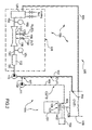
Figure 2 which shows a plant that implements a method for the cooling and the re-titration of conductive solutions, in particular conductive solutions of lead-acid batteries, according to the present invention, it may be seen that theplant 100 comprises at least onestorage vessel 106 containing quantities of conductive solutions which have, for example, the same first concentration "C1" of sulphuric acid previously mentioned and that have a substantially cold temperature indicated again, for simplicity, as "T1". - The
storage vessel 106 discharges, for example by gravity, through afirst pipe 105, quantities of conductive solutions into a lead-acid battery 101 being charged, which has twoterminals 102 and 103 which are schematically connected to a source of electricity, such as, for example, a domestic or industrial distribution network, labelled 104. - The
first pipe 105 discharges inside thebattery 101 through aninlet duct 107 installed for this purpose, whilst, through anoutlet duct 108, corresponding quantities of conductive solutions are extracted or forced outside thebattery 101. - These conductive solutions, which are either extracted or forced out, have a second concentration "C2" which is different, and normally greater, than the first concentration "C1" and also have a temperature "T2" greater than the temperature "T1", and are, therefore, heated.
- These conductive solutions are pumped by a
first pump 111 to a correction device delimited overall by thedotted line 110 and which will be described in greater detail below, passing through asecond pipe 109. - According to the present invention, the
storage vessel 106 has at least onesecond outlet 114 from which runs athird pipe 115 parallel to thesecond pipe 109 and larger in diameter than thesecond pipe 109 to enable the passage of proportionally greater flows. - The
third pipe 115 flows into asecond pump 116, and serves to integrate, by means of thesame pump 116, the flow of conductive solution coming from the battery, orbatteries 101, which is sent to thecorrection device 110. In this manner, the flow of conductive solution which is treated in thecorrection device 110 is always constant regardless of the number ofbatteries 101 under charge. - In a possible embodiment, the
second pipe 109 and thethird pipe 115 converge at ajunction point 117, placed immediately upstream of thepump 116. - The
correction device 110 comprises afiltering unit 112 which serves to filter any impurities which are collected by the conductive solutions inside thebattery 101 during charging. - A device for continuous density adjustment is fitted downstream of the
filtering unit 112 which serves for adjusting and re-titrating the conductive solution. The above-mentioned adjustment device is also known as static continuous mixer-adding device and is labelled 113. - Into the mixer-adding
device 113 converge twosupply lines regulation devices 130, water (indicated inFigure 2 by H2O) and sulphuric acid (indicated inFigure 2 by H2SO4), respectively. The regulation devices may embodied by modulatingvalves 130 which enable the introduction of calibrated and proportional fluid flows upon opening of the valve. Therefore, if required, the mixer-addingdevice 113 may be used to add water and/or sulphuric acid to the conductive solution in order to correct the concentration of sulphuric acid in the conductive solution after filtration of the conductive solution with thefiltering unit 112. - Upstream and downstream of the mixer-adding
device 113 two devices are installed for measuring the concentrations of sulphuric acid in the conductive solution, labelled 131 and 132, respectively. - A
cooling unit 120 is fitted downstream of the mixer-addingdevice 113, for cooling the conductive solutions when they leave the mixer-addingdevice 113. - As may be seen in
Figure 2 , thesecond pump 116, thefiltering unit 112, thestatic mixer 113 and thecooling unit 120 are connected by a connection pipe labelled 133 which extends from an outlet of thecooling unit 120 to thestorage vessel 106. - The method for the cooling and the re-titration of conductive solutions, in particular conductive solutions of
batteries 101, is as follows: a pre-established quantity of a conductive solution which has a concentration of sulphuric acid "C1" and a temperature "T1" is placed inside thestorage vessel 106. - From this
storage vessel 106 the conductive solution is introduced into abattery 101. More precisely, the conductive solution is introduced into thebattery 101, for example by gravity, by thefirst pipe 105, through theinlet duct 107 entering the battery. - The
battery 101 is in turn placed under charge, that is, connected to anelectricity source 104, such as, for example, a conventional domestic or industrial distribution network. - It should be noted that the cooling and re-titrating method described for a
single battery 101 is also applicable to a plurality ofbatteries 101 placed in series and charged simultaneously. - Due to the chemical reactions caused by charging, the conductive solution which is already present in the
battery 101 has a concentration of sulphuric acid "C2", which is normally more concentrated, and generally different to the concentration "C1", and a temperature "T2" which is higher than the temperature "T1". - The introduction of conductive solution at the temperature "T1" and at the concentration "C1" takes place continuously and, consequently, the conductive solution which has concentration "C2" and temperature "T2" is forced outside the
battery 101 through thebattery outlet duct 108 and sent through thesecond pipe 109 to thecorrection device 110. - However, before reaching the
correction device 110, the conductive solution, which has concentration "C2" and temperature "T2", is mixed with a conductive solution which has concentration "C1" and temperature "T1" and that, coming from thestorage vessel 106, is sent to thejunction point 117 through thethird pipe 115. - The conductive solution, coming from the
storage vessel 106 and thebattery 101, or from thebatteries 101, is then filtered by means of thefiltering unit 112 and then passed to the mixer-addingdevice 113 in which the concentration of the conductive solution is corrected, or re-titrated, in order to return to a concentration value substantially equal to the value "C1". - The correction occurs in the mixer-adding
device 113 automatically, without the presence of operators. - After the conductive solution has been corrected in the mixer-adding
device 113, the conductive solution is introduced into thecooling unit 120 in which the temperature is lowered to a value close to or equal to the value "T1". - Lastly, the cooled conductive solution is sent again to the
storage vessel 106 through thefourth pipe 133, so that the cooling and correction cycle can continue until the charging of thebattery 101 is completed. - An important characteristic of the present invention is that the conductive solution circulates continuously in the two
circuits - The conductive solution is circulated by taking it from the
vessel 106 and returning it to the same vessel through the twocircuits - The
first circuit 134 basically comprises thefirst pipe 105, the battery or thebatteries 101, thesecond pipe 109 and thepump 111, whilst thesecond circuit 135 comprises thethird pipe 115, thepump 116, thefourth pipe 133, thefiltering unit 112, the mixer-addingdevice 113 and thecooling unit 120. - As mentioned above, the solution coming from the
first circuit 134 has a concentration "C2" and a temperature "T2", which are in general different from those of thesecond circuit 135, which has a concentration "C1" and a temperature T1. - Since the introduction of the solution coming from the
first circuit 134 takes place upstream of the mixer-adding device 113 - and in particular takes place upstream of the pump 116 - the mixer-addingdevice 113 carries out the overall re-titration, or correction of the concentration, of the solution. - The
pump 111 ensures that the solution coming from thefirst circuit 134 is effectively and efficiently introduced into thesecond circuit 135, and for that purpose thepump 111 must be selected in order to provide a head greater than the head present in thesecond circuit 135 at thejunction point 117 of the two circuits. - According to a preferred embodiment of the present invention, the
first circuit 134 may comprise a group of circuits, each circuit in turn comprising thefirst pipe 105, thebatteries 101, thesecond pipe 109 and thepump 111. - Indeed, as will be described in more detail below, the
batteries 101 may be subdivided into several groups which are at different charging stages. - Since all the
pumps 111 of the various groups ofbatteries 101 lead into thesecond circuit 135, thepump 116 of thecircuit 135 must have a flow rate greater than the overall flow rate of all thepumps 111. - In the
second circuit 135 there is in any case a substantially constant circulation achieved by thepump 116. - The fact of having the flow of conductive solution to be treated substantially constant in the
circuit 135 enables the correction and the re-titration to be carried out effectively and in real time. - The
first measurement device 131 fitted upstream of the mixer-addingdevice 113 measures the current concentration "C1" of the conductive solution which flows overall in thecircuit 135. Since the flow of conductive solution is constant, it is possible to calculate easily, quickly and precisely the quantity of water or acid necessary to obtain the "set-point", that is the desired concentration of conductive solution to be introduced into the batteries. - The
second measurement device 132, installed downstream of the mixer-addingdevice 113, checks the concentration of the conductive solution after the correction, and on the basis of the difference with respect to the "set point", or desired concentration, of the conductive solution, modifies the operating factor of the modulatingvalves 130 that supplies the water and the acid. - In a simplified version of the present invention (not illustrated), the
second measurement device 132, installed downstream of the mixer-addingdevice 113, may be omitted, since adjustment of the operating factor of the modulatingvalves 130 may be obtained by trial and error during the preparation and setting up of the plant. - The entire operation of the plant, and in particular the checking of the concentration of the conductive solution and the operation of the modulating
valves 130 for the correction of the concentration, may be performed by a microprocessor control unit (not illustrated), provided with a dedicated software. - The re-titration, or correction of the concentration, of the solution is performed by the mixer-adding
device 113 on the solution circulating in the twocircuits batteries 101 being charged in thefirst circuit 134. - In this respect, it should be noted that the above-mentioned re-titration of the solution does not require large quantities of acid or water either with a
single battery 101, or withmany batteries 101. - Indeed, in the case of
many batteries 101 under charge, the batteries will be subdivided into several groups with different charge start times and, consequently, charging and resting at different times. The subdivision of the batteries to be charged into groups is necessary in order to maintain electricity consumption within certain limits and to not have excessively high electricity consumption peaks. - The concentration of the conductive solution in the batteries follows, in a similar manner, the electrical charging, rest and/or discharge steps of the batteries.
- Since the conductive solution increases in density while the
batteries 101 are charging and reduces in density while resting or discharging, there will be a group ofbatteries 101 which provides a conductive solution with a higher density and a group ofbatteries 101 which provides a conductive solution with a lower density. - Therefore, the conductive solution in circulation will have overall an intermediate concentration between these density values.
- In particular, the concentration will depend on the number of
batteries 101, that is, the flow of conductive solution supplied by the batteries themsleves, and the electrical state of the batteries: charging, rest or discharging. - In this manner, it is possible to obtain a certain balancing effect of the concentration of the conductive solution. The correction or re-titration carried out by the mixer-adding
device 113 does not require large quantities of acid or water even in the above-mentioned case in which there are many or all the batteries which the plant is able to prepare. - Naturally, in the case of a small number of batteries which are all at the same electrical charging stage, the flow of conductive solution provided by the
batteries 101 will be relatively small and, therefore, large quantities of acid or water will not be required for the correction mixer-addingdevice 113 in this case either. - For the above-mentioned reasons, the size of the mixer-adding
device 113 will be selected to provide corrections to only a certain number of batteries, and this number will be certainly less than the maximum number of batteries which may be processed by the plant. - As already indicated previously, the mixer-adding
device 113, even if it is designed to correct a flow of conductive solution only for a small number of batteries, is still able to treat the conductive solution of all the batteries even when the plant operates with the maximum number of batteries which may be processed in the plant, as the batteries are subdivided into groups at different charging stages. With the present invention, the cooling and re-titration plant is altogether smaller and more compact than prior art plants which correct the conductive solution in the collection and/or storage vessels, and it is also less costly to construct and to operate as it is fully automatic. The quantity of conductive solution in circulation is also much less as the collection and/or storage vessels of the prior art plants are not necessary, and it is sufficient to have a single storage vessel which may have a relatively small volume compared to the number of batteries treated.
Claims (31)
- A method for the cooling of conductive solutions, in particular of lead-acid batteries (101) during charging, containing an acid solution in a first concentration (C1) and having a first temperature (T1), the method comprising: extracting from the batteries (101) first quantities of the conductive solutions when they have a second concentration (C2) and a second temperature (T2) substantially different from the first concentration (C1) and first temperature (T1); correcting the second concentration (C2) and the second temperature (T2) substantially towards the first concentration (C1) and the first temperature (T1), and being characterised in that the step of correcting the second concentration (C2) takes place by circulating second quantities of conductive solutions with a constant flow rate.
- The method according to claim 1, wherein the step of extracting the first quantities of conductive solutions from the batteries (101) takes place in a continuous manner.
- The method according to claim 1 or 2, wherein the step of correcting the second temperature (T2) takes place by circulating a constant flow of conductive solutions.
- The method according to any of the foregoing claims, wherein the first quantities are again introduced into the batteries (101) after the correcting step.
- The method according to any of the foregoing claims, wherein the step of correcting the constant flow rate of conductive solutions takes place cyclically.
- The method according to any of the foregoing claims, wherein the step for introducing again the first quantities in the batteries (101) takes place cyclically.
- The method according to any of the foregoing claims, comprising filtering the conductive solutions and obtaining filtered quantities.
- The method according to any of the foregoing claims, wherein the correcting step comprises continuously adjusting the densities of the quantities of conductive solutions by continuous density adjustment means, obtaining adjusted quantities.
- The method according to claim 8, wherein the adjustment step comprises measuring the concentration of the conductive solutions.
- The method according to any of the foregoing claims, comprising cooling the quantities of conductive solutions with cooling means (120).
- The method according to any of the claims from 8 to 10, wherein the adjustment step comprises adding an acid and/or a solvent liquid.
- The method according to claim 11, wherein the acid comprises sulphuric acid.
- The method according to claim 11 or 12, wherein the solvent liquid comprises water.
- The method according to any of the claims from 8 to 13, wherein the adjustment means comprise devices for the continuous adjustment of density or concentration of the conductive solutions, known as static mixers-adding devices (113).
- The method according to any of the claims from 11 to 14, wherein the step for adding an acid and/or a solvent liquid takes place by adjustable flow rate means (130).
- The method according to any of the claims from 8 to 15, wherein the adjustment step is controlled by microprocessor means.
- A plant (100) for the cooling and the re-titration of conductive solutions, in particular of lead-acid batteries (101) during charging, comprising means (106) for storing the conductive solutions containing an acid solution in a first concentration (C1) and having a first temperature (T1); first connection means (105) between the storage means (106) and an inlet duct (107) to the batteries (101); means (110) for correcting first quantities of the conductive solutions extracted by an outlet duct (108) from the batteries (101) and having a second concentration (C2) and a second temperature (T2) different from the first concentration (C1) and the first temperature (T1) and connected to the outlet duct (108) by the second connection means (109, 111); characterised in that the correction means (110) are crossed by a constant flow rate of conductive solutions.'
- The plant according to claim 17, comprising the third connection means (115, 116) fitted between the storage means (106) and the correction means (110).
- The plant according to claim 18, wherein the second connection means (109, 111) and the third connection means (115, 116) converge at a junction point (117) upstream of the correction means (110).
- The plant according to any of the claims from 17 to 19, wherein the second connection means comprise a first pump (111).
- The plant according to any of the claims from 17 to 19, wherein the second connection means comprise a plurality of first pumps (111).
- The plant according to any of the claims from 18 to 21, wherein the third connection means comprise a second pump (116).
- The plant according to claim 22, wherein the first pump (111), or the plurality of first pumps (111), has, or have, a head greater than the head present at the junction point (117).
- The plant according to claim 22 or 23, wherein the junction point (117) is upstream of the second pump (116).
- The plant according to any of the claims from 22 to 24, wherein the second pump (116) has a greater flow rate than the flow rate of the first pump (111), or the second pump (116) has a greater flow rate than the overall flow rate of the plurality of first pumps (111).
- The plant according to any of the claims from 17 to 25, wherein the correction means (110) comprise, connected together by pipes: the filtration means (112); the continuous mixing-adding means (113, 130) for correcting the second concentration (C2); the cooling means (120) of the second temperature; the fourth connection means (133) fitted between the cooling means (120) and the storage means (106).
- The plant according to claim 26, wherein the continuous mixing means comprise a continuous density adjustment device, known as static mixer-adding device (113).
- The plant according to claim 27, wherein a concentration measurement device (131) is fitted upstream of the static mixer-adding device (113).
- The plant according to claim 27 or 28, wherein a concentration measurement device (132) is fitted downstream of the static mixer-adding device (113).
- The plant according to any of the claims from 27 to 29, wherein the continuous density adjustment device comprises adjustable flow rate means (130) for adding acid and/or solvent liquid.
- The plant according to any of the claims from 27 to 30, wherein the continuous mixing means are controlled by microprocessor means.
Priority Applications (1)
| Application Number | Priority Date | Filing Date | Title |
|---|---|---|---|
| EP20080425226 EP2107625B1 (en) | 2008-04-04 | 2008-04-04 | Plant for cooling and retitration of conductive solutions |
Applications Claiming Priority (1)
| Application Number | Priority Date | Filing Date | Title |
|---|---|---|---|
| EP20080425226 EP2107625B1 (en) | 2008-04-04 | 2008-04-04 | Plant for cooling and retitration of conductive solutions |
Publications (2)
| Publication Number | Publication Date |
|---|---|
| EP2107625A1 true EP2107625A1 (en) | 2009-10-07 |
| EP2107625B1 EP2107625B1 (en) | 2012-11-14 |
Family
ID=39682496
Family Applications (1)
| Application Number | Title | Priority Date | Filing Date |
|---|---|---|---|
| EP20080425226 Active EP2107625B1 (en) | 2008-04-04 | 2008-04-04 | Plant for cooling and retitration of conductive solutions |
Country Status (1)
| Country | Link |
|---|---|
| EP (1) | EP2107625B1 (en) |
Cited By (4)
| Publication number | Priority date | Publication date | Assignee | Title |
|---|---|---|---|---|
| US20130071701A1 (en) * | 2011-09-21 | 2013-03-21 | Tesla Motors, Inc. | Response to High Voltage Electrolysis of Coolant in a Battery Pack |
| US8862414B2 (en) | 2011-09-21 | 2014-10-14 | Tesla Motors, Inc. | Detection of high voltage electrolysis of coolant in a battery pack |
| CN109772248A (en) * | 2019-03-25 | 2019-05-21 | 安吉润风空气净化科技有限公司 | A kind of dielectric barrier plasma discharge reactor with refrigerating function |
| US11515587B2 (en) * | 2019-10-10 | 2022-11-29 | Robert Bosch Gmbh | Physics-based control of battery temperature |
Citations (6)
| Publication number | Priority date | Publication date | Assignee | Title |
|---|---|---|---|---|
| US3166447A (en) | 1959-08-19 | 1965-01-19 | Varta Ag | Apparatus for forming, charging and discharging the electrode plates of a storage battery with an acid electrolyte |
| DE3529726A1 (en) | 1985-08-20 | 1987-03-05 | Varta Batterie | METHOD AND DEVICE FOR OPERATING A LEAD BATTERY WITH ELECTROLYTE-FLOWED ELECTRODES |
| EP0476916A1 (en) | 1990-09-13 | 1992-03-25 | Westinghouse Electric Corporation | Aluminum-silver oxide battery system |
| US5135820A (en) | 1991-02-14 | 1992-08-04 | Jones William E M | Apparatus for recirculation of battery electrolyte and method of using same |
| JPH0745302A (en) | 1993-07-29 | 1995-02-14 | Shin Kobe Electric Mach Co Ltd | Battery case forming method and device and battery case forming jig |
| US20080016680A1 (en) * | 2004-09-16 | 2008-01-24 | Jean Ruch | Method And Device For Producing A Maintenance-Free Battery Having A Fixed Electrolyte |
-
2008
- 2008-04-04 EP EP20080425226 patent/EP2107625B1/en active Active
Patent Citations (6)
| Publication number | Priority date | Publication date | Assignee | Title |
|---|---|---|---|---|
| US3166447A (en) | 1959-08-19 | 1965-01-19 | Varta Ag | Apparatus for forming, charging and discharging the electrode plates of a storage battery with an acid electrolyte |
| DE3529726A1 (en) | 1985-08-20 | 1987-03-05 | Varta Batterie | METHOD AND DEVICE FOR OPERATING A LEAD BATTERY WITH ELECTROLYTE-FLOWED ELECTRODES |
| EP0476916A1 (en) | 1990-09-13 | 1992-03-25 | Westinghouse Electric Corporation | Aluminum-silver oxide battery system |
| US5135820A (en) | 1991-02-14 | 1992-08-04 | Jones William E M | Apparatus for recirculation of battery electrolyte and method of using same |
| JPH0745302A (en) | 1993-07-29 | 1995-02-14 | Shin Kobe Electric Mach Co Ltd | Battery case forming method and device and battery case forming jig |
| US20080016680A1 (en) * | 2004-09-16 | 2008-01-24 | Jean Ruch | Method And Device For Producing A Maintenance-Free Battery Having A Fixed Electrolyte |
Cited By (6)
| Publication number | Priority date | Publication date | Assignee | Title |
|---|---|---|---|---|
| US20130071701A1 (en) * | 2011-09-21 | 2013-03-21 | Tesla Motors, Inc. | Response to High Voltage Electrolysis of Coolant in a Battery Pack |
| US8862414B2 (en) | 2011-09-21 | 2014-10-14 | Tesla Motors, Inc. | Detection of high voltage electrolysis of coolant in a battery pack |
| US9966590B2 (en) * | 2011-09-21 | 2018-05-08 | Tesla, Inc. | Response to high voltage electrolysis of coolant in a battery pack |
| US10714735B2 (en) | 2011-09-21 | 2020-07-14 | Tesla, Inc. | Response to high voltage electrolysis of coolant in a battery pack |
| CN109772248A (en) * | 2019-03-25 | 2019-05-21 | 安吉润风空气净化科技有限公司 | A kind of dielectric barrier plasma discharge reactor with refrigerating function |
| US11515587B2 (en) * | 2019-10-10 | 2022-11-29 | Robert Bosch Gmbh | Physics-based control of battery temperature |
Also Published As
| Publication number | Publication date |
|---|---|
| EP2107625B1 (en) | 2012-11-14 |
Similar Documents
| Publication | Publication Date | Title |
|---|---|---|
| CN110182924B (en) | Full-automatic ammonia preparing and adding integrated machine device and full-automatic ammonia preparing and adding method | |
| US7655098B2 (en) | Readying cooling circuits for use in fuel cells | |
| DE102017126333B4 (en) | Fuel cell cooling system | |
| DE3744840C2 (en) | ||
| CN105953989A (en) | Water-cooling testbed for testing water-cooling board of power module | |
| CN204289633U (en) | A kind of cooling water recirculation system be internalized into for lead acid accumulator | |
| DE102015117333B4 (en) | Fuel cell system | |
| US20110086279A1 (en) | Fluid cooling apparatus for a fuel cell device and fuel cell system | |
| EP2107625B1 (en) | Plant for cooling and retitration of conductive solutions | |
| DE102019119970A1 (en) | The fuel cell system | |
| CN108776025B (en) | Thermal management system test platform of electric drive system | |
| CN217955921U (en) | Purging control device for fuel cell system | |
| CN100499219C (en) | Method for forming lead-acid batteries and device for implementing said method | |
| CN111816894A (en) | Fuel cell heat management device and control method thereof | |
| CN113772772A (en) | Dissolved oxygen removal device, internal cooling water system of converter valve and dissolved oxygen removal method thereof | |
| DE102019120085A1 (en) | Processing method for a fuel cell system, component detachment method and fuel cell system | |
| CN107543141B (en) | Steam generator analogue body water supply system and control method during increasing temperature and pressure | |
| US10131554B2 (en) | Mobile water cart with water pre-conditioning device | |
| CN205355983U (en) | 1000MW steam turbine power generation machine stator water cooling device | |
| CN119573368A (en) | Drying equipment | |
| CN107036833A (en) | The scaling method and calibration system of radiator performance parameter | |
| CN206421826U (en) | A kind of low temperature water release device improves the device of the extreme incident response of Natural Circulation | |
| CN211238399U (en) | Fuel cell coolant temperature monitoring device | |
| CN215640145U (en) | Engine oil consumption measuring and controlling device | |
| CN116315304A (en) | Flow-equalizing and pressure-regulating method for multi-stage liquid cooling pipeline |
Legal Events
| Date | Code | Title | Description |
|---|---|---|---|
| PUAI | Public reference made under article 153(3) epc to a published international application that has entered the european phase |
Free format text: ORIGINAL CODE: 0009012 |
|
| AK | Designated contracting states |
Kind code of ref document: A1 Designated state(s): AT BE BG CH CY CZ DE DK EE ES FI FR GB GR HR HU IE IS IT LI LT LU LV MC MT NL NO PL PT RO SE SI SK TR |
|
| AX | Request for extension of the european patent |
Extension state: AL BA MK RS |
|
| 17P | Request for examination filed |
Effective date: 20100407 |
|
| AKX | Designation fees paid |
Designated state(s): AT BE BG CH CY CZ DE DK EE ES FI FR GB GR HR HU IE IS IT LI LT LU LV MC MT NL NO PL PT RO SE SI SK TR |
|
| AXX | Extension fees paid |
Extension state: AL Payment date: 20100407 Extension state: BA Payment date: 20100407 Extension state: RS Payment date: 20100407 Extension state: MK Payment date: 20100407 |
|
| 17Q | First examination report despatched |
Effective date: 20110909 |
|
| RTI1 | Title (correction) |
Free format text: PLANT FOR COOLING AND RETITRATION OF CONDUCTIVE SOLUTIONS |
|
| GRAP | Despatch of communication of intention to grant a patent |
Free format text: ORIGINAL CODE: EPIDOSNIGR1 |
|
| GRAS | Grant fee paid |
Free format text: ORIGINAL CODE: EPIDOSNIGR3 |
|
| GRAA | (expected) grant |
Free format text: ORIGINAL CODE: 0009210 |
|
| AK | Designated contracting states |
Kind code of ref document: B1 Designated state(s): AT BE BG CH CY CZ DE DK EE ES FI FR GB GR HR HU IE IS IT LI LT LU LV MC MT NL NO PL PT RO SE SI SK TR |
|
| AX | Request for extension of the european patent |
Extension state: AL BA MK RS |
|
| REG | Reference to a national code |
Ref country code: GB Ref legal event code: FG4D |
|
| REG | Reference to a national code |
Ref country code: AT Ref legal event code: REF Ref document number: 584385 Country of ref document: AT Kind code of ref document: T Effective date: 20121115 Ref country code: CH Ref legal event code: EP |
|
| REG | Reference to a national code |
Ref country code: IE Ref legal event code: FG4D |
|
| REG | Reference to a national code |
Ref country code: DE Ref legal event code: R096 Ref document number: 602008020086 Country of ref document: DE Effective date: 20130110 |
|
| REG | Reference to a national code |
Ref country code: NL Ref legal event code: VDEP Effective date: 20121114 |
|
| REG | Reference to a national code |
Ref country code: AT Ref legal event code: MK05 Ref document number: 584385 Country of ref document: AT Kind code of ref document: T Effective date: 20121114 |
|
| REG | Reference to a national code |
Ref country code: LT Ref legal event code: MG4D |
|
| PG25 | Lapsed in a contracting state [announced via postgrant information from national office to epo] |
Ref country code: ES Free format text: LAPSE BECAUSE OF FAILURE TO SUBMIT A TRANSLATION OF THE DESCRIPTION OR TO PAY THE FEE WITHIN THE PRESCRIBED TIME-LIMIT Effective date: 20130225 Ref country code: LT Free format text: LAPSE BECAUSE OF FAILURE TO SUBMIT A TRANSLATION OF THE DESCRIPTION OR TO PAY THE FEE WITHIN THE PRESCRIBED TIME-LIMIT Effective date: 20121114 Ref country code: HR Free format text: LAPSE BECAUSE OF FAILURE TO SUBMIT A TRANSLATION OF THE DESCRIPTION OR TO PAY THE FEE WITHIN THE PRESCRIBED TIME-LIMIT Effective date: 20121114 Ref country code: FI Free format text: LAPSE BECAUSE OF FAILURE TO SUBMIT A TRANSLATION OF THE DESCRIPTION OR TO PAY THE FEE WITHIN THE PRESCRIBED TIME-LIMIT Effective date: 20121114 Ref country code: SE Free format text: LAPSE BECAUSE OF FAILURE TO SUBMIT A TRANSLATION OF THE DESCRIPTION OR TO PAY THE FEE WITHIN THE PRESCRIBED TIME-LIMIT Effective date: 20121114 Ref country code: NO Free format text: LAPSE BECAUSE OF FAILURE TO SUBMIT A TRANSLATION OF THE DESCRIPTION OR TO PAY THE FEE WITHIN THE PRESCRIBED TIME-LIMIT Effective date: 20130214 |
|
| PG25 | Lapsed in a contracting state [announced via postgrant information from national office to epo] |
Ref country code: PL Free format text: LAPSE BECAUSE OF FAILURE TO SUBMIT A TRANSLATION OF THE DESCRIPTION OR TO PAY THE FEE WITHIN THE PRESCRIBED TIME-LIMIT Effective date: 20121114 Ref country code: CY Free format text: LAPSE BECAUSE OF FAILURE TO SUBMIT A TRANSLATION OF THE DESCRIPTION OR TO PAY THE FEE WITHIN THE PRESCRIBED TIME-LIMIT Effective date: 20121114 Ref country code: BE Free format text: LAPSE BECAUSE OF FAILURE TO SUBMIT A TRANSLATION OF THE DESCRIPTION OR TO PAY THE FEE WITHIN THE PRESCRIBED TIME-LIMIT Effective date: 20121114 Ref country code: LV Free format text: LAPSE BECAUSE OF FAILURE TO SUBMIT A TRANSLATION OF THE DESCRIPTION OR TO PAY THE FEE WITHIN THE PRESCRIBED TIME-LIMIT Effective date: 20121114 Ref country code: PT Free format text: LAPSE BECAUSE OF FAILURE TO SUBMIT A TRANSLATION OF THE DESCRIPTION OR TO PAY THE FEE WITHIN THE PRESCRIBED TIME-LIMIT Effective date: 20130314 Ref country code: SI Free format text: LAPSE BECAUSE OF FAILURE TO SUBMIT A TRANSLATION OF THE DESCRIPTION OR TO PAY THE FEE WITHIN THE PRESCRIBED TIME-LIMIT Effective date: 20121114 Ref country code: GR Free format text: LAPSE BECAUSE OF FAILURE TO SUBMIT A TRANSLATION OF THE DESCRIPTION OR TO PAY THE FEE WITHIN THE PRESCRIBED TIME-LIMIT Effective date: 20130215 |
|
| PG25 | Lapsed in a contracting state [announced via postgrant information from national office to epo] |
Ref country code: AT Free format text: LAPSE BECAUSE OF FAILURE TO SUBMIT A TRANSLATION OF THE DESCRIPTION OR TO PAY THE FEE WITHIN THE PRESCRIBED TIME-LIMIT Effective date: 20121114 |
|
| PG25 | Lapsed in a contracting state [announced via postgrant information from national office to epo] |
Ref country code: BG Free format text: LAPSE BECAUSE OF FAILURE TO SUBMIT A TRANSLATION OF THE DESCRIPTION OR TO PAY THE FEE WITHIN THE PRESCRIBED TIME-LIMIT Effective date: 20130214 Ref country code: EE Free format text: LAPSE BECAUSE OF FAILURE TO SUBMIT A TRANSLATION OF THE DESCRIPTION OR TO PAY THE FEE WITHIN THE PRESCRIBED TIME-LIMIT Effective date: 20121114 Ref country code: CZ Free format text: LAPSE BECAUSE OF FAILURE TO SUBMIT A TRANSLATION OF THE DESCRIPTION OR TO PAY THE FEE WITHIN THE PRESCRIBED TIME-LIMIT Effective date: 20121114 Ref country code: SK Free format text: LAPSE BECAUSE OF FAILURE TO SUBMIT A TRANSLATION OF THE DESCRIPTION OR TO PAY THE FEE WITHIN THE PRESCRIBED TIME-LIMIT Effective date: 20121114 Ref country code: DK Free format text: LAPSE BECAUSE OF FAILURE TO SUBMIT A TRANSLATION OF THE DESCRIPTION OR TO PAY THE FEE WITHIN THE PRESCRIBED TIME-LIMIT Effective date: 20121114 |
|
| PG25 | Lapsed in a contracting state [announced via postgrant information from national office to epo] |
Ref country code: NL Free format text: LAPSE BECAUSE OF FAILURE TO SUBMIT A TRANSLATION OF THE DESCRIPTION OR TO PAY THE FEE WITHIN THE PRESCRIBED TIME-LIMIT Effective date: 20121114 Ref country code: RO Free format text: LAPSE BECAUSE OF FAILURE TO SUBMIT A TRANSLATION OF THE DESCRIPTION OR TO PAY THE FEE WITHIN THE PRESCRIBED TIME-LIMIT Effective date: 20121114 |
|
| PLBE | No opposition filed within time limit |
Free format text: ORIGINAL CODE: 0009261 |
|
| STAA | Information on the status of an ep patent application or granted ep patent |
Free format text: STATUS: NO OPPOSITION FILED WITHIN TIME LIMIT |
|
| 26N | No opposition filed |
Effective date: 20130815 |
|
| PG25 | Lapsed in a contracting state [announced via postgrant information from national office to epo] |
Ref country code: MC Free format text: LAPSE BECAUSE OF FAILURE TO SUBMIT A TRANSLATION OF THE DESCRIPTION OR TO PAY THE FEE WITHIN THE PRESCRIBED TIME-LIMIT Effective date: 20121114 |
|
| REG | Reference to a national code |
Ref country code: CH Ref legal event code: PL |
|
| REG | Reference to a national code |
Ref country code: DE Ref legal event code: R097 Ref document number: 602008020086 Country of ref document: DE Effective date: 20130815 |
|
| GBPC | Gb: european patent ceased through non-payment of renewal fee |
Effective date: 20130404 |
|
| REG | Reference to a national code |
Ref country code: IE Ref legal event code: MM4A |
|
| PG25 | Lapsed in a contracting state [announced via postgrant information from national office to epo] |
Ref country code: GB Free format text: LAPSE BECAUSE OF NON-PAYMENT OF DUE FEES Effective date: 20130404 Ref country code: LI Free format text: LAPSE BECAUSE OF NON-PAYMENT OF DUE FEES Effective date: 20130430 Ref country code: CH Free format text: LAPSE BECAUSE OF NON-PAYMENT OF DUE FEES Effective date: 20130430 |
|
| REG | Reference to a national code |
Ref country code: FR Ref legal event code: ST Effective date: 20131231 |
|
| PG25 | Lapsed in a contracting state [announced via postgrant information from national office to epo] |
Ref country code: FR Free format text: LAPSE BECAUSE OF NON-PAYMENT OF DUE FEES Effective date: 20130430 |
|
| PG25 | Lapsed in a contracting state [announced via postgrant information from national office to epo] |
Ref country code: IE Free format text: LAPSE BECAUSE OF NON-PAYMENT OF DUE FEES Effective date: 20130404 |
|
| PG25 | Lapsed in a contracting state [announced via postgrant information from national office to epo] |
Ref country code: MT Free format text: LAPSE BECAUSE OF FAILURE TO SUBMIT A TRANSLATION OF THE DESCRIPTION OR TO PAY THE FEE WITHIN THE PRESCRIBED TIME-LIMIT Effective date: 20121114 |
|
| PG25 | Lapsed in a contracting state [announced via postgrant information from national office to epo] |
Ref country code: TR Free format text: LAPSE BECAUSE OF FAILURE TO SUBMIT A TRANSLATION OF THE DESCRIPTION OR TO PAY THE FEE WITHIN THE PRESCRIBED TIME-LIMIT Effective date: 20121114 |
|
| PG25 | Lapsed in a contracting state [announced via postgrant information from national office to epo] |
Ref country code: HU Free format text: LAPSE BECAUSE OF FAILURE TO SUBMIT A TRANSLATION OF THE DESCRIPTION OR TO PAY THE FEE WITHIN THE PRESCRIBED TIME-LIMIT; INVALID AB INITIO Effective date: 20080404 Ref country code: LU Free format text: LAPSE BECAUSE OF NON-PAYMENT OF DUE FEES Effective date: 20130404 |
|
| PG25 | Lapsed in a contracting state [announced via postgrant information from national office to epo] |
Ref country code: IS Free format text: LAPSE BECAUSE OF FAILURE TO SUBMIT A TRANSLATION OF THE DESCRIPTION OR TO PAY THE FEE WITHIN THE PRESCRIBED TIME-LIMIT Effective date: 20121114 |
|
| REG | Reference to a national code |
Ref country code: DE Ref legal event code: R079 Ref document number: 602008020086 Country of ref document: DE Free format text: PREVIOUS MAIN CLASS: H01M0002400000 Ipc: H01M0050770000 |
|
| P01 | Opt-out of the competence of the unified patent court (upc) registered |
Effective date: 20230306 |
|
| PGFP | Annual fee paid to national office [announced via postgrant information from national office to epo] |
Ref country code: DE Payment date: 20250422 Year of fee payment: 18 |
|
| PGFP | Annual fee paid to national office [announced via postgrant information from national office to epo] |
Ref country code: IT Payment date: 20250328 Year of fee payment: 18 |