EP2107341A1 - A system for monitoring and controlling consumer appliances through an energy service provider - Google Patents
A system for monitoring and controlling consumer appliances through an energy service provider Download PDFInfo
- Publication number
- EP2107341A1 EP2107341A1 EP08300165A EP08300165A EP2107341A1 EP 2107341 A1 EP2107341 A1 EP 2107341A1 EP 08300165 A EP08300165 A EP 08300165A EP 08300165 A EP08300165 A EP 08300165A EP 2107341 A1 EP2107341 A1 EP 2107341A1
- Authority
- EP
- European Patent Office
- Prior art keywords
- metering device
- management device
- appliance
- request
- monitoring
- Prior art date
- Legal status (The legal status is an assumption and is not a legal conclusion. Google has not performed a legal analysis and makes no representation as to the accuracy of the status listed.)
- Ceased
Links
- 238000012544 monitoring process Methods 0.000 title claims abstract description 22
- 230000005540 biological transmission Effects 0.000 claims abstract description 17
- 230000004044 response Effects 0.000 claims abstract description 12
- 238000005265 energy consumption Methods 0.000 claims abstract description 9
- 230000008859 change Effects 0.000 claims abstract description 3
- 230000005611 electricity Effects 0.000 claims description 10
- VNWKTOKETHGBQD-UHFFFAOYSA-N methane Chemical compound C VNWKTOKETHGBQD-UHFFFAOYSA-N 0.000 claims description 6
- 239000003345 natural gas Substances 0.000 claims description 3
- -1 district heat Substances 0.000 claims description 2
- XLYOFNOQVPJJNP-UHFFFAOYSA-N water Substances O XLYOFNOQVPJJNP-UHFFFAOYSA-N 0.000 claims description 2
- 230000004913 activation Effects 0.000 description 4
- 238000000034 method Methods 0.000 description 3
- 238000004378 air conditioning Methods 0.000 description 1
- 238000013459 approach Methods 0.000 description 1
- 230000008901 benefit Effects 0.000 description 1
- 230000001413 cellular effect Effects 0.000 description 1
- 238000012508 change request Methods 0.000 description 1
- 239000003795 chemical substances by application Substances 0.000 description 1
- 238000004891 communication Methods 0.000 description 1
- 238000004590 computer program Methods 0.000 description 1
- 239000004020 conductor Substances 0.000 description 1
- 230000003111 delayed effect Effects 0.000 description 1
- 230000001419 dependent effect Effects 0.000 description 1
- 238000011161 development Methods 0.000 description 1
- 230000018109 developmental process Effects 0.000 description 1
- 235000021158 dinner Nutrition 0.000 description 1
- 238000005516 engineering process Methods 0.000 description 1
- 239000004973 liquid crystal related substance Substances 0.000 description 1
- 238000004519 manufacturing process Methods 0.000 description 1
- 238000005259 measurement Methods 0.000 description 1
- 238000010295 mobile communication Methods 0.000 description 1
- 239000008239 natural water Substances 0.000 description 1
- 238000010248 power generation Methods 0.000 description 1
- 238000012545 processing Methods 0.000 description 1
- 230000000153 supplemental effect Effects 0.000 description 1
Images
Classifications
-
- G—PHYSICS
- G01—MEASURING; TESTING
- G01D—MEASURING NOT SPECIALLY ADAPTED FOR A SPECIFIC VARIABLE; ARRANGEMENTS FOR MEASURING TWO OR MORE VARIABLES NOT COVERED IN A SINGLE OTHER SUBCLASS; TARIFF METERING APPARATUS; MEASURING OR TESTING NOT OTHERWISE PROVIDED FOR
- G01D4/00—Tariff metering apparatus
- G01D4/002—Remote reading of utility meters
-
- Y—GENERAL TAGGING OF NEW TECHNOLOGICAL DEVELOPMENTS; GENERAL TAGGING OF CROSS-SECTIONAL TECHNOLOGIES SPANNING OVER SEVERAL SECTIONS OF THE IPC; TECHNICAL SUBJECTS COVERED BY FORMER USPC CROSS-REFERENCE ART COLLECTIONS [XRACs] AND DIGESTS
- Y02—TECHNOLOGIES OR APPLICATIONS FOR MITIGATION OR ADAPTATION AGAINST CLIMATE CHANGE
- Y02B—CLIMATE CHANGE MITIGATION TECHNOLOGIES RELATED TO BUILDINGS, e.g. HOUSING, HOUSE APPLIANCES OR RELATED END-USER APPLICATIONS
- Y02B90/00—Enabling technologies or technologies with a potential or indirect contribution to GHG emissions mitigation
- Y02B90/20—Smart grids as enabling technology in buildings sector
-
- Y—GENERAL TAGGING OF NEW TECHNOLOGICAL DEVELOPMENTS; GENERAL TAGGING OF CROSS-SECTIONAL TECHNOLOGIES SPANNING OVER SEVERAL SECTIONS OF THE IPC; TECHNICAL SUBJECTS COVERED BY FORMER USPC CROSS-REFERENCE ART COLLECTIONS [XRACs] AND DIGESTS
- Y04—INFORMATION OR COMMUNICATION TECHNOLOGIES HAVING AN IMPACT ON OTHER TECHNOLOGY AREAS
- Y04S—SYSTEMS INTEGRATING TECHNOLOGIES RELATED TO POWER NETWORK OPERATION, COMMUNICATION OR INFORMATION TECHNOLOGIES FOR IMPROVING THE ELECTRICAL POWER GENERATION, TRANSMISSION, DISTRIBUTION, MANAGEMENT OR USAGE, i.e. SMART GRIDS
- Y04S20/00—Management or operation of end-user stationary applications or the last stages of power distribution; Controlling, monitoring or operating thereof
- Y04S20/30—Smart metering, e.g. specially adapted for remote reading
Definitions
- the invention relates to a system for monitoring and controlling consumer appliances through an energy service provider according to the preamble of claim 1.
- a smart meter generally refers to a type of advanced meter that identifies consumption in more detail than a conventional meter and optionally, but generally, communicates that information via some network back to the local utility for monitoring and billing purposes.
- the term "smart meter” typically refers to an electrical meter, but the term is also occasionally applied to the measurement of natural gas and water consumption. Similar meters usually referred to as time-of-use or interval meters have existed for years but smart meters usually involve a different technology mix such as real-time or near real-time reads, power outage notification, and power quality monitoring. Smart meters are also believed to be a less costly alternative to traditional interval or time-of-use meters and are intended to be implemented on a wide scale to all customer classes, including residential customers.
- United States Patent No. US 6,980,973 B1 discloses an example of a smart utility meter and associated payment service.
- a downside of this known solution is its inability to control the attached consumer devices in addition to monitoring their energy consumption.
- An object of the invention is thus to propose an improved approach to smart metering that allows for remote control of the monitored appliances.
- a main idea of the invention is the reuse of known smart metering infrastructures for the additional purpose of home automation.
- Home automation also called domotics, is a field within building automation specializing in the automation requirements of private homes and in the application of automation techniques for the comfort and security of their residents.
- building automation techniques such as light and climate control, control of doors and window shutters, and security and surveillance systems are also used in home automation
- additional functions include the control of multi-media home entertainment systems, automatic plant watering and pet feeding, automatic scenes for dinners and parties, and a more user-friendly control interface.
- a system for monitoring and controlling consumer appliances through an energy service provider comprises a metering device for monitoring energy consumption by an appliance.
- This metering device in turn comprises energy monitoring circuitry as well as an interface to a data transmission network.
- the metering device further interfaces a controller for controlling the appliance.
- the system comprises a management device located remotely from the metering device.
- This management device interfaces the metering device through the data transmission network.
- the management device transmits instructions to the metering device. These instructions tell the metering device how to control the appliance to comply with the client request.
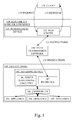
- Fig. 1 schematically shows a system according to an embodiment of the invention for monitoring and controlling consumer appliances through an electricity supplier.
- Fig. 1 shows a client 131, electricity supplier's premises 120, a data transmission network 110, and a private home 100.
- a management device 121 is located on the electricity supplier's premises 120 and comprises a web server 122.
- a metering device 102, a controller 108, and appliances 103, 104, 105 are located in the private home 100, the metering device 102 comprising power monitoring circuitry 106 and an interface 107.
- the client 131 is configured to transmit a request 130 to the web server 122 and receive a corresponding response 133.
- the web server 122 in turn is connected through the data transmission network 110 with the interface 107 for sending instructions 132 to the interface 107. Additionally, the web server may 122 may be configured for receiving data such as metering information (not depicted) from the interface 107.
- the metering device 102 is connected with each of the appliances 103, 104, and 105 through the controller 108.
- an electricity supplier is used as an example of an energy service provider.
- Other embodiments of the invention may pertain to the distribution of energy by means of, for example, natural gas, district heat, or water.
- the system of Fig. 1 interfaces three appliances 103, 104, and 105, each connected indirectly to the metering device 102.
- This metering device 102 contains conventional power monitoring circuitry 106 for monitoring power consumption by the appliances 103, 104, and 105, as may be used in a traditional power meter.
- the metering device 102 is also configured to monitor power generation by the appliances 103, 104, and 105.
- the metering device 102 comprises a display (not depicted) for information on current or accumulated energy consumption by the appliances 103, 104, and 105. Additionally, the cost associated with these consumption data may be displayed.
- the display is mainly intended for use by residents of the home where the metering device 102 and attached appliances 103, 104, and 105 are installed. Liquid crystal displays (LCDs) are commonly employed for this purpose.
- the metering device 102 contains the interface 107 to the data transmission network 110.
- the data transmission network 110 takes the form of a local telephone network to which the metering device may be connected by means of a digital subscriber line (DSL).
- DSL digital subscriber line
- An alternative embodiment may make use of a wireless network such as the Global System for Mobile Communications (GSM) or Worldwide Interoperability for Microwave Access (WiMAX), standardized as IEEE 802.16, without deviating from the spirit of the invention.
- GSM Global System for Mobile Communications
- WiMAX Worldwide Interoperability for Microwave Access
- the metering device 102 interfaces the controller 108 that may be integrated with the metering device, integrated with any or each of the appliances, or external to both the metering device and the appliances.
- the controller 108 may take the form of a programmable logic controller, also known as a programmable controller, as used in the automation of industrial processes.
- the controller 108 may be connected to the appliances 104, 104, and 105 by means of a wireless link, power line communication (PLC), or other electrical conductors.
- PLC power line communication
- the controller 108 communicates with the attached appliances 103, 104, and 105 by means of a short-range in-house protocol.
- Several domotic standards for controlling appliances have been defined and include INSTEON, X10, and PLC BUS.
- the management device 121 Located remotely from the metering device 102 and connected to it through the data transmission network 110 is the management device 121, operated centrally by the electricity supplier on its premises 120.
- the management device 121 may take the form of a general-purpose computer running adapted software, or it may be a piece of hardware specifically configured for the task at hand.
- the management device 121 will include functionality for monitoring consumption information received from the metering device 102 for billing purposes. This feature is known in the art as telemetering.
- the management device 121 is capable of receiving requests 130 from the client 131.
- requests 130 pertain to the operational state of any of the appliances within the scope of the metering device 102 and controller 108.
- Selectable operational states are diverse and depend on the type of appliance controlled. For example, a simple household device supports only the basic operational states of "on” and "off", a heater supports a plurality of temperatures, and an air conditioning system supports selected levels of humidity.
- a request 130 would typically comprise the desired state of the appliance, possibly along with a time constraint for performing the indicated change of state.
- the management device 121 Upon receiving a request 130, the management device 121 generates, based on the contents of the request 130, a set of instructions 132 for execution by the metering device 102 or controller 108.
- the instructions 132 may be identical to the request 130 or may be specifically adapted to the data transmission network 110, metering device 102, or subject appliance 103, 104, or 105.
- the management device 121 may also use an internal or external database to convert or enrich the request 130 for the purpose of generating the instructions 132.
- the resulting instructions 132 are transmitted to the metering device 102 by means of the data transmission network 110.
- the client 131 may take the form of a standard personal computer, a personal digital assistant (PDA) or cellular mobile phone. It may be running a software provided by the electricity supplier, delivered as part of the operating system, or obtained from a third-party vendor.
- PDA personal digital assistant
- a mobile client 131 provides the further advantage that its user, typically the electricity subscriber, is enabled to control his or her appliances remotely, such as away from home. Potential applications of this capability are known from the field of home automation.
- the management device 121 comprises a web server 122.
- web server is meant a computer program responsible for accepting HTTP requests from the client 131 and serving it HTTP responses along with optional data content.
- the term “web server” may also refer to a computer that runs a program as described above.) Consequently, the request 130 is transferred according to HTTP, and will be answered by the corresponding HTTP response 133.
- the client 131 comprises an HTTP user agent, commonly known as a web browser.
- the web server 122 Upon accepting request 130, the web server 122 generates an HTML document (not depicted) and returns it to the client 131 as part of the response 133. This document contains an acknowledgment of the request 130 as well as supplemental information provided by the management device 121.
- the system comprises a load control system.
- load control is meant a method of ensuring that the electrical load on the distribution system does not exceed the amount that can be generated by the electricity supplier.
- the management device will monitor predefined trigger conditions and act accordingly if any of these are met.
- trigger conditions may include a threshold of the load imposed on the power grid.
- trigger conditions may be based on the current time, as the wholesale price of energy varies widely throughout the day. If a trigger condition is met, for example, indicating a peak load of the grid, the management device will instruct the metering device to curtail energy consumption by some or all of the attached appliances.
- the management device in addition to the energy curtailment described above, may also choose to activate appliances that are waiting to be served. Such activation may take place upon detecting the presence of excess energy in the distribution network. Eligibility of an appliance for delayed activation may be signaled to the management device by the metering device when consumption data are transmitted.
- the management system may take into account the expected energy requirement of the respective appliance based on recent use statistics.
- subscribers may prioritize the energy requirements of each appliance. Depending on the assigned priority, the energy service provider commits to supplying an appliance within a specified timeframe. Reversely, subscribers are charged according to their requested priorities. For example, energy that is requested to be delivered immediately is associated with a higher cost compared to energy delivered in response to a lower priority request. Thus, subscribers are offered an incentive for leaving more flexibility to the energy service provider.
Landscapes
- Physics & Mathematics (AREA)
- General Physics & Mathematics (AREA)
- Telephonic Communication Services (AREA)
- Selective Calling Equipment (AREA)
Abstract
The invention concerns a system for monitoring and controlling consumer appliances through an energy service provider, the system comprising a metering device for monitoring energy consumption by an appliance, the metering device comprising power monitoring circuitry and an interface to a data transmission network, and the system comprising a management device located remotely from the metering device, the management device interfacing the metering device through the data transmission network, wherein the metering device interfaces a controller for controlling the appliance, the management device is configured to accept a request from a client, the request comprising an operational state change of the appliance, and the management device is further configured, in response to accepting the request, to transmit instructions for controlling the appliance to the metering device through the data transmission network.
Description
- The invention relates to a system for monitoring and controlling consumer appliances through an energy service provider according to the preamble of claim 1.
- A smart meter generally refers to a type of advanced meter that identifies consumption in more detail than a conventional meter and optionally, but generally, communicates that information via some network back to the local utility for monitoring and billing purposes. The term "smart meter" typically refers to an electrical meter, but the term is also occasionally applied to the measurement of natural gas and water consumption. Similar meters usually referred to as time-of-use or interval meters have existed for years but smart meters usually involve a different technology mix such as real-time or near real-time reads, power outage notification, and power quality monitoring. Smart meters are also believed to be a less costly alternative to traditional interval or time-of-use meters and are intended to be implemented on a wide scale to all customer classes, including residential customers.
- United States Patent No.
US 6,980,973 B1 discloses an example of a smart utility meter and associated payment service. A downside of this known solution is its inability to control the attached consumer devices in addition to monitoring their energy consumption. An object of the invention is thus to propose an improved approach to smart metering that allows for remote control of the monitored appliances. - This object is achieved by a system according to the teaching of claim 1.
- A main idea of the invention is the reuse of known smart metering infrastructures for the additional purpose of home automation. Home automation, also called domotics, is a field within building automation specializing in the automation requirements of private homes and in the application of automation techniques for the comfort and security of their residents. While building automation techniques such as light and climate control, control of doors and window shutters, and security and surveillance systems are also used in home automation, additional functions include the control of multi-media home entertainment systems, automatic plant watering and pet feeding, automatic scenes for dinners and parties, and a more user-friendly control interface.
- Further developments of the invention can be gathered from the dependent claims and the following description.
- In the following the invention will be explained further making reference to the attached drawings.
- A system for monitoring and controlling consumer appliances through an energy service provider comprises a metering device for monitoring energy consumption by an appliance. This metering device in turn comprises energy monitoring circuitry as well as an interface to a data transmission network. The metering device further interfaces a controller for controlling the appliance.
- In addition to the metering device, the system comprises a management device located remotely from the metering device. This management device interfaces the metering device through the data transmission network. In response to an operational state change request from a client, the management device transmits instructions to the metering device. These instructions tell the metering device how to control the appliance to comply with the client request.
-
Fig. 1 schematically shows a system according to an embodiment of the invention for monitoring and controlling consumer appliances through an electricity supplier. - In the following, a system according to the invention is elucidated by way of example, referencing
Fig. 1 . -
Fig. 1 shows aclient 131, electricity supplier's premises 120, adata transmission network 110, and aprivate home 100. Amanagement device 121 is located on the electricity supplier's premises 120 and comprises aweb server 122. - A
metering device 102, acontroller 108, andappliances private home 100, themetering device 102 comprisingpower monitoring circuitry 106 and aninterface 107. - The
client 131 is configured to transmit arequest 130 to theweb server 122 and receive acorresponding response 133. Theweb server 122 in turn is connected through thedata transmission network 110 with theinterface 107 for sendinginstructions 132 to theinterface 107. Additionally, the web server may 122 may be configured for receiving data such as metering information (not depicted) from theinterface 107. Themetering device 102 is connected with each of theappliances controller 108. - In the system of
Fig. 1 , an electricity supplier is used as an example of an energy service provider. Other embodiments of the invention may pertain to the distribution of energy by means of, for example, natural gas, district heat, or water. - The system of
Fig. 1 interfaces threeappliances metering device 102. Thismetering device 102 contains conventionalpower monitoring circuitry 106 for monitoring power consumption by theappliances appliances metering device 102 is also configured to monitor power generation by theappliances - Although not a necessity, the
metering device 102 comprises a display (not depicted) for information on current or accumulated energy consumption by theappliances metering device 102 and attachedappliances - In addition to the monitoring circuitry, the
metering device 102 contains theinterface 107 to thedata transmission network 110. Typically, thedata transmission network 110 takes the form of a local telephone network to which the metering device may be connected by means of a digital subscriber line (DSL). An alternative embodiment may make use of a wireless network such as the Global System for Mobile Communications (GSM) or Worldwide Interoperability for Microwave Access (WiMAX), standardized as IEEE 802.16, without deviating from the spirit of the invention. - For controlling the
appliances metering device 102 interfaces thecontroller 108 that may be integrated with the metering device, integrated with any or each of the appliances, or external to both the metering device and the appliances. Thecontroller 108 may take the form of a programmable logic controller, also known as a programmable controller, as used in the automation of industrial processes. Thecontroller 108 may be connected to theappliances controller 108 communicates with the attachedappliances - Located remotely from the
metering device 102 and connected to it through thedata transmission network 110 is themanagement device 121, operated centrally by the electricity supplier on its premises 120. Themanagement device 121 may take the form of a general-purpose computer running adapted software, or it may be a piece of hardware specifically configured for the task at hand. Typically, themanagement device 121 will include functionality for monitoring consumption information received from themetering device 102 for billing purposes. This feature is known in the art as telemetering. - In addition to its connection to the
metering device 102 through thedata transmission network 110, themanagement device 121 is capable of receivingrequests 130 from theclient 131.Such requests 130 pertain to the operational state of any of the appliances within the scope of themetering device 102 andcontroller 108. Selectable operational states are diverse and depend on the type of appliance controlled. For example, a simple household device supports only the basic operational states of "on" and "off", a heater supports a plurality of temperatures, and an air conditioning system supports selected levels of humidity. For any of these appliances, arequest 130 would typically comprise the desired state of the appliance, possibly along with a time constraint for performing the indicated change of state. - Upon receiving a
request 130, themanagement device 121 generates, based on the contents of therequest 130, a set ofinstructions 132 for execution by themetering device 102 orcontroller 108. Theinstructions 132 may be identical to therequest 130 or may be specifically adapted to thedata transmission network 110,metering device 102, orsubject appliance management device 121 may also use an internal or external database to convert or enrich therequest 130 for the purpose of generating theinstructions 132. Eventually, the resultinginstructions 132 are transmitted to themetering device 102 by means of thedata transmission network 110. - The
client 131 may take the form of a standard personal computer, a personal digital assistant (PDA) or cellular mobile phone. It may be running a software provided by the electricity supplier, delivered as part of the operating system, or obtained from a third-party vendor. Amobile client 131 provides the further advantage that its user, typically the electricity subscriber, is enabled to control his or her appliances remotely, such as away from home. Potential applications of this capability are known from the field of home automation. - In the given embodiment, to connect the
client 131 to themanagement device 121 by means of a standard transport protocol, themanagement device 121 comprises aweb server 122. By web server is meant a computer program responsible for accepting HTTP requests from theclient 131 and serving it HTTP responses along with optional data content. (The term "web server" may also refer to a computer that runs a program as described above.) Consequently, therequest 130 is transferred according to HTTP, and will be answered by thecorresponding HTTP response 133. For the purpose of creating theHTTP request 130 and theHTTP response 133, theclient 131 comprises an HTTP user agent, commonly known as a web browser. Upon acceptingrequest 130, theweb server 122 generates an HTML document (not depicted) and returns it to theclient 131 as part of theresponse 133. This document contains an acknowledgment of therequest 130 as well as supplemental information provided by themanagement device 121. - In an alternative embodiment of the invention, to allow the balancing of load imposed on the underlying energy distribution network, the system comprises a load control system. By load control is meant a method of ensuring that the electrical load on the distribution system does not exceed the amount that can be generated by the electricity supplier. In addition to processing client requests, the management device will monitor predefined trigger conditions and act accordingly if any of these are met. Such trigger conditions may include a threshold of the load imposed on the power grid. Alternatively or in addition, trigger conditions may be based on the current time, as the wholesale price of energy varies widely throughout the day. If a trigger condition is met, for example, indicating a peak load of the grid, the management device will instruct the metering device to curtail energy consumption by some or all of the attached appliances.
- In a further embodiment, to allow for the automatic activation of appliances during off-peak hours, the management device, in addition to the energy curtailment described above, may also choose to activate appliances that are waiting to be served. Such activation may take place upon detecting the presence of excess energy in the distribution network. Eligibility of an appliance for delayed activation may be signaled to the management device by the metering device when consumption data are transmitted. When generating a schedule for appliance activation, the management system may take into account the expected energy requirement of the respective appliance based on recent use statistics. As a more advanced feature, subscribers may prioritize the energy requirements of each appliance. Depending on the assigned priority, the energy service provider commits to supplying an appliance within a specified timeframe. Reversely, subscribers are charged according to their requested priorities. For example, energy that is requested to be delivered immediately is associated with a higher cost compared to energy delivered in response to a lower priority request. Thus, subscribers are offered an incentive for leaving more flexibility to the energy service provider.
Claims (13)
- A system for monitoring and controlling consumer appliances through an energy service provider (120), the system comprising
a metering device (102) for monitoring energy consumption by an appliance (103, 104, 105), the metering device (102) comprising power monitoring circuitry (106) and an interface (107) to a data transmission network (110), and
a management device (121) located remotely from the metering device (102), the management device (121) interfacing the metering device (102) through the data transmission network (110),
characterized in that
the metering device (102) interfaces a controller (108) for controlling the appliance (103, 104, 105),
the management device (121) is configured to accept a request (130) from a client (131), the request (130) comprising an operational state change of the appliance, and
the management device (121) is further configured, in response to accepting the request (130), to transmit instructions (132) for controlling the appliance (103, 104, 105) to the metering device (102) through the data transmission network (110). - A system according to claim 1, characterized in that the energy service provider (120) is a public utility and energy distribution is effected by either of the following:electric power,natural gas,district heat, andwater.
- A system according to claim 2, characterized in that the metering device 102 is further configured for monitoring electricity generation by the appliance (103, 104, 105).
- A system according to claim 1, characterized in that the management device (121) comprises a web server (122) and the request (130) is an HTTP request.
- A system according to claim 4, characterized in that the management device (121) is further configured, in response to accepting the request (130), to serve the client (131) an HTTP response (133) comprising an HTML document.
- A system according to claim 1, characterized in that the system comprises a load control system and that the management device (121) is further configured, in response to a trigger condition, to transmit instructions for curtailing energy consumption by the appliance (103, 104, 105) to the metering device (102) through the data transmission network (110).
- A system according to claim 6, characterized in that the trigger condition comprises at least one of the following:a threshold of the load imposed on the energy distribution system operated by the energy service provider (120) anda time of day.
- A system according to claim 1, characterized in that the interface (107) interfaces a local telephone network and that the metering device (102) and the management device (121) are configured for communicating by means of a digital subscriber line.
- A system according to claim 1, characterized in that the interface (107) interfaces a wireless network, that the metering device (102) and the management device (121) each interface a radio transmitter and a radio receiver, and that the metering device (102) and the management device (121) are configured for communicating through electromagnetic waves of radio frequency.
- A system according to claim 9, characterized in that the interface (107) interfaces a GSM network and that the metering device (102) and the management device (121) are configured for communicating by means of a General Packet Radio Service.
- A system according to claim 9, characterized in that the interface (107) comprises a WiMAX subscriber unit, that the management device (121) comprises a WiMAX base station, and that the metering device (102) and the management device (121) are configured for communicating according to the IEEE 802.16 standard.
- A system according to claim 1, characterized in that the metering device (102) and the appliance (103, 104, 105) are connected by either of the following domotic standards:INSTEON,X10, andPLC BUS.
- A system according to claim 1, characterized in that the metering device (102) comprises a display unit for displaying information on at least one of the following:energy consumption by the appliance (103, 104, 105) andinformation on the cost of energy consumption by the appliance (103, 104, 105).
Priority Applications (1)
| Application Number | Priority Date | Filing Date | Title |
|---|---|---|---|
| EP08300165A EP2107341A1 (en) | 2008-03-31 | 2008-03-31 | A system for monitoring and controlling consumer appliances through an energy service provider |
Applications Claiming Priority (1)
| Application Number | Priority Date | Filing Date | Title |
|---|---|---|---|
| EP08300165A EP2107341A1 (en) | 2008-03-31 | 2008-03-31 | A system for monitoring and controlling consumer appliances through an energy service provider |
Publications (1)
| Publication Number | Publication Date |
|---|---|
| EP2107341A1 true EP2107341A1 (en) | 2009-10-07 |
Family
ID=39735395
Family Applications (1)
| Application Number | Title | Priority Date | Filing Date |
|---|---|---|---|
| EP08300165A Ceased EP2107341A1 (en) | 2008-03-31 | 2008-03-31 | A system for monitoring and controlling consumer appliances through an energy service provider |
Country Status (1)
| Country | Link |
|---|---|
| EP (1) | EP2107341A1 (en) |
Cited By (5)
| Publication number | Priority date | Publication date | Assignee | Title |
|---|---|---|---|---|
| GB2480504A (en) * | 2010-05-20 | 2011-11-23 | Nicholas Hughes | Mobile phone device control and metering |
| WO2012012882A1 (en) * | 2010-07-26 | 2012-02-02 | Gerald Michael O'brien | System and method for on-location resource consumption monitoring and management |
| US9020852B2 (en) | 2011-03-08 | 2015-04-28 | D.Light Design, Inc. | Systems and methods for activation and deactivation of appliances |
| WO2017065818A1 (en) * | 2015-10-16 | 2017-04-20 | Mueller International, Llc. | Selective delivery state change of valve of remote metering device |
| EP3431931A1 (en) * | 2017-07-18 | 2019-01-23 | Kamstrup A/S | Smart metering device providing adaptive service level |
Citations (6)
| Publication number | Priority date | Publication date | Assignee | Title |
|---|---|---|---|---|
| US4351028A (en) * | 1979-02-21 | 1982-09-21 | South Eastern Electricity Board | Meters for measuring electrical energy consumption |
| US5146067A (en) * | 1990-01-12 | 1992-09-08 | Cic Systems, Inc. | Prepayment metering system using encoded purchase cards from multiple locations |
| GB2313462A (en) * | 1996-05-24 | 1997-11-26 | Landis & Gyr Ag | Metering systems |
| US20040130459A1 (en) * | 2002-09-13 | 2004-07-08 | Ramirez Anibal Diego | Electricity meter having gas consumption correction processing |
| US6980973B1 (en) | 1999-09-07 | 2005-12-27 | Visa International Service Association | Self-paying smart utility meter and payment service |
| WO2007146053A2 (en) * | 2006-06-06 | 2007-12-21 | Hudson Bay Wireless Llc | Electrical power metering system |
-
2008
- 2008-03-31 EP EP08300165A patent/EP2107341A1/en not_active Ceased
Patent Citations (6)
| Publication number | Priority date | Publication date | Assignee | Title |
|---|---|---|---|---|
| US4351028A (en) * | 1979-02-21 | 1982-09-21 | South Eastern Electricity Board | Meters for measuring electrical energy consumption |
| US5146067A (en) * | 1990-01-12 | 1992-09-08 | Cic Systems, Inc. | Prepayment metering system using encoded purchase cards from multiple locations |
| GB2313462A (en) * | 1996-05-24 | 1997-11-26 | Landis & Gyr Ag | Metering systems |
| US6980973B1 (en) | 1999-09-07 | 2005-12-27 | Visa International Service Association | Self-paying smart utility meter and payment service |
| US20040130459A1 (en) * | 2002-09-13 | 2004-07-08 | Ramirez Anibal Diego | Electricity meter having gas consumption correction processing |
| WO2007146053A2 (en) * | 2006-06-06 | 2007-12-21 | Hudson Bay Wireless Llc | Electrical power metering system |
Cited By (11)
| Publication number | Priority date | Publication date | Assignee | Title |
|---|---|---|---|---|
| GB2480504A (en) * | 2010-05-20 | 2011-11-23 | Nicholas Hughes | Mobile phone device control and metering |
| WO2012012882A1 (en) * | 2010-07-26 | 2012-02-02 | Gerald Michael O'brien | System and method for on-location resource consumption monitoring and management |
| US9020852B2 (en) | 2011-03-08 | 2015-04-28 | D.Light Design, Inc. | Systems and methods for activation and deactivation of appliances |
| US9052702B2 (en) | 2011-03-08 | 2015-06-09 | D. Light Design, Inc. | Systems and methods for activation and deactivation of appliances |
| US9799018B2 (en) | 2011-03-08 | 2017-10-24 | D.Light Design, Inc. | Systems and methods for activation and deactivation of appliances |
| WO2017065818A1 (en) * | 2015-10-16 | 2017-04-20 | Mueller International, Llc. | Selective delivery state change of valve of remote metering device |
| US11064271B2 (en) | 2015-10-16 | 2021-07-13 | Mueller International, Llc | Selective delivery state change of valve of remote metering device |
| US11490176B2 (en) | 2015-10-16 | 2022-11-01 | Mueller International, Llc | Selective delivery state change of valve of remote metering device |
| EP3431931A1 (en) * | 2017-07-18 | 2019-01-23 | Kamstrup A/S | Smart metering device providing adaptive service level |
| US10935394B2 (en) | 2017-07-18 | 2021-03-02 | Kamstrup A/S | Smart metering device providing adaptive service level |
| US11209287B2 (en) | 2017-07-18 | 2021-12-28 | Kamstrup A/S | Smart metering device providing adaptive service level |
Similar Documents
| Publication | Publication Date | Title |
|---|---|---|
| CA2752987C (en) | Low cost and flexible energy management system with a scheduling capability | |
| US8095233B1 (en) | Interconnected premises equipment for energy management | |
| US8260470B2 (en) | System and method for selective disconnection of electrical service to end customers | |
| KR101073114B1 (en) | A method and a system for automatic management of demand for non-durables | |
| Moura et al. | The role of Smart Grids to foster energy efficiency | |
| EP2418462A1 (en) | Sub-metering hardware for measuring energy data of an energy consuming device | |
| EP2592788A1 (en) | Utility powered communication gateway | |
| US20130009788A1 (en) | Utility Electric Meter Web Server | |
| MX2012000906A (en) | Energy management system and method. | |
| KR20120101003A (en) | System, method and apparatus for advanced utility control, monitoring and conservation | |
| EP2107341A1 (en) | A system for monitoring and controlling consumer appliances through an energy service provider | |
| AU2011205064B2 (en) | Diagnostics using sub-metering device | |
| WO2010132469A2 (en) | System and method for selective disconnection of electrical service to end customers | |
| KR20090032411A (en) | A power management system that provides various power service policies in real time in connection with consumer power consumption | |
| CN105229893A (en) | Management devices, device management method, management system | |
| WO2014015370A1 (en) | Method and apparatus for remote energy monitoring and control | |
| US20150097693A1 (en) | In-premises management of home area networks | |
| SE1551127A1 (en) | A wireless sensor network | |
| CA2752414A1 (en) | Low cost home energy manager adaptor | |
| Andrésen | Technical and economical aspects of remote data transmission ways for smart metering | |
| Çanakçi | Remote metering the energy delivered or absorbed by wind turbine | |
| HK1195364A (en) | Utility electric meter web server |
Legal Events
| Date | Code | Title | Description |
|---|---|---|---|
| PUAI | Public reference made under article 153(3) epc to a published international application that has entered the european phase |
Free format text: ORIGINAL CODE: 0009012 |
|
| AK | Designated contracting states |
Kind code of ref document: A1 Designated state(s): AT BE BG CH CY CZ DE DK EE ES FI FR GB GR HR HU IE IS IT LI LT LU LV MC MT NL NO PL PT RO SE SI SK TR |
|
| AX | Request for extension of the european patent |
Extension state: AL BA MK RS |
|
| STAA | Information on the status of an ep patent application or granted ep patent |
Free format text: STATUS: THE APPLICATION HAS BEEN REFUSED |
|
| 18R | Application refused |
Effective date: 20091224 |