EP2107225A1 - Internal combustion engine and method for controlling the internal combustion engine - Google Patents
Internal combustion engine and method for controlling the internal combustion engine Download PDFInfo
- Publication number
- EP2107225A1 EP2107225A1 EP09156821A EP09156821A EP2107225A1 EP 2107225 A1 EP2107225 A1 EP 2107225A1 EP 09156821 A EP09156821 A EP 09156821A EP 09156821 A EP09156821 A EP 09156821A EP 2107225 A1 EP2107225 A1 EP 2107225A1
- Authority
- EP
- European Patent Office
- Prior art keywords
- valve
- opening amount
- engine
- closing
- manner
- Prior art date
- Legal status (The legal status is an assumption and is not a legal conclusion. Google has not performed a legal analysis and makes no representation as to the accuracy of the status listed.)
- Granted
Links
Images


Classifications
-
- F—MECHANICAL ENGINEERING; LIGHTING; HEATING; WEAPONS; BLASTING
- F02—COMBUSTION ENGINES; HOT-GAS OR COMBUSTION-PRODUCT ENGINE PLANTS
- F02D—CONTROLLING COMBUSTION ENGINES
- F02D23/00—Controlling engines characterised by their being supercharged
- F02D23/02—Controlling engines characterised by their being supercharged the engines being of fuel-injection type
-
- F—MECHANICAL ENGINEERING; LIGHTING; HEATING; WEAPONS; BLASTING
- F02—COMBUSTION ENGINES; HOT-GAS OR COMBUSTION-PRODUCT ENGINE PLANTS
- F02B—INTERNAL-COMBUSTION PISTON ENGINES; COMBUSTION ENGINES IN GENERAL
- F02B39/00—Component parts, details, or accessories relating to, driven charging or scavenging pumps, not provided for in groups F02B33/00 - F02B37/00
- F02B39/16—Other safety measures for, or other control of, pumps
-
- F—MECHANICAL ENGINEERING; LIGHTING; HEATING; WEAPONS; BLASTING
- F02—COMBUSTION ENGINES; HOT-GAS OR COMBUSTION-PRODUCT ENGINE PLANTS
- F02D—CONTROLLING COMBUSTION ENGINES
- F02D13/00—Controlling the engine output power by varying inlet or exhaust valve operating characteristics, e.g. timing
- F02D13/02—Controlling the engine output power by varying inlet or exhaust valve operating characteristics, e.g. timing during engine operation
- F02D13/0203—Variable control of intake and exhaust valves
- F02D13/0215—Variable control of intake and exhaust valves changing the valve timing only
- F02D13/0219—Variable control of intake and exhaust valves changing the valve timing only by shifting the phase, i.e. the opening periods of the valves are constant
-
- F—MECHANICAL ENGINEERING; LIGHTING; HEATING; WEAPONS; BLASTING
- F02—COMBUSTION ENGINES; HOT-GAS OR COMBUSTION-PRODUCT ENGINE PLANTS
- F02D—CONTROLLING COMBUSTION ENGINES
- F02D13/00—Controlling the engine output power by varying inlet or exhaust valve operating characteristics, e.g. timing
- F02D13/02—Controlling the engine output power by varying inlet or exhaust valve operating characteristics, e.g. timing during engine operation
- F02D13/0223—Variable control of the intake valves only
- F02D13/0234—Variable control of the intake valves only changing the valve timing only
- F02D13/0238—Variable control of the intake valves only changing the valve timing only by shifting the phase, i.e. the opening periods of the valves are constant
-
- F—MECHANICAL ENGINEERING; LIGHTING; HEATING; WEAPONS; BLASTING
- F02—COMBUSTION ENGINES; HOT-GAS OR COMBUSTION-PRODUCT ENGINE PLANTS
- F02D—CONTROLLING COMBUSTION ENGINES
- F02D13/00—Controlling the engine output power by varying inlet or exhaust valve operating characteristics, e.g. timing
- F02D13/02—Controlling the engine output power by varying inlet or exhaust valve operating characteristics, e.g. timing during engine operation
- F02D13/0242—Variable control of the exhaust valves only
- F02D13/0249—Variable control of the exhaust valves only changing the valve timing only
-
- F—MECHANICAL ENGINEERING; LIGHTING; HEATING; WEAPONS; BLASTING
- F02—COMBUSTION ENGINES; HOT-GAS OR COMBUSTION-PRODUCT ENGINE PLANTS
- F02D—CONTROLLING COMBUSTION ENGINES
- F02D41/00—Electrical control of supply of combustible mixture or its constituents
- F02D41/0002—Controlling intake air
- F02D41/0007—Controlling intake air for control of turbo-charged or super-charged engines
-
- F—MECHANICAL ENGINEERING; LIGHTING; HEATING; WEAPONS; BLASTING
- F02—COMBUSTION ENGINES; HOT-GAS OR COMBUSTION-PRODUCT ENGINE PLANTS
- F02D—CONTROLLING COMBUSTION ENGINES
- F02D41/00—Electrical control of supply of combustible mixture or its constituents
- F02D41/02—Circuit arrangements for generating control signals
- F02D41/14—Introducing closed-loop corrections
- F02D41/1438—Introducing closed-loop corrections using means for determining characteristics of the combustion gases; Sensors therefor
- F02D41/1444—Introducing closed-loop corrections using means for determining characteristics of the combustion gases; Sensors therefor characterised by the characteristics of the combustion gases
- F02D41/1448—Introducing closed-loop corrections using means for determining characteristics of the combustion gases; Sensors therefor characterised by the characteristics of the combustion gases the characteristics being an exhaust gas pressure
-
- F—MECHANICAL ENGINEERING; LIGHTING; HEATING; WEAPONS; BLASTING
- F02—COMBUSTION ENGINES; HOT-GAS OR COMBUSTION-PRODUCT ENGINE PLANTS
- F02D—CONTROLLING COMBUSTION ENGINES
- F02D41/00—Electrical control of supply of combustible mixture or its constituents
- F02D41/22—Safety or indicating devices for abnormal conditions
-
- F—MECHANICAL ENGINEERING; LIGHTING; HEATING; WEAPONS; BLASTING
- F02—COMBUSTION ENGINES; HOT-GAS OR COMBUSTION-PRODUCT ENGINE PLANTS
- F02B—INTERNAL-COMBUSTION PISTON ENGINES; COMBUSTION ENGINES IN GENERAL
- F02B37/00—Engines characterised by provision of pumps driven at least for part of the time by exhaust
- F02B37/12—Control of the pumps
- F02B37/18—Control of the pumps by bypassing exhaust from the inlet to the outlet of turbine or to the atmosphere
-
- F—MECHANICAL ENGINEERING; LIGHTING; HEATING; WEAPONS; BLASTING
- F02—COMBUSTION ENGINES; HOT-GAS OR COMBUSTION-PRODUCT ENGINE PLANTS
- F02D—CONTROLLING COMBUSTION ENGINES
- F02D13/00—Controlling the engine output power by varying inlet or exhaust valve operating characteristics, e.g. timing
- F02D13/02—Controlling the engine output power by varying inlet or exhaust valve operating characteristics, e.g. timing during engine operation
- F02D13/0261—Controlling the valve overlap
-
- F—MECHANICAL ENGINEERING; LIGHTING; HEATING; WEAPONS; BLASTING
- F02—COMBUSTION ENGINES; HOT-GAS OR COMBUSTION-PRODUCT ENGINE PLANTS
- F02D—CONTROLLING COMBUSTION ENGINES
- F02D11/00—Arrangements for, or adaptations to, non-automatic engine control initiation means, e.g. operator initiated
- F02D11/06—Arrangements for, or adaptations to, non-automatic engine control initiation means, e.g. operator initiated characterised by non-mechanical control linkages, e.g. fluid control linkages or by control linkages with power drive or assistance
- F02D11/10—Arrangements for, or adaptations to, non-automatic engine control initiation means, e.g. operator initiated characterised by non-mechanical control linkages, e.g. fluid control linkages or by control linkages with power drive or assistance of the electric type
- F02D2011/108—Arrangements for, or adaptations to, non-automatic engine control initiation means, e.g. operator initiated characterised by non-mechanical control linkages, e.g. fluid control linkages or by control linkages with power drive or assistance of the electric type with means for detecting or resolving a stuck throttle, e.g. when being frozen in a position
-
- F—MECHANICAL ENGINEERING; LIGHTING; HEATING; WEAPONS; BLASTING
- F02—COMBUSTION ENGINES; HOT-GAS OR COMBUSTION-PRODUCT ENGINE PLANTS
- F02D—CONTROLLING COMBUSTION ENGINES
- F02D41/00—Electrical control of supply of combustible mixture or its constituents
- F02D41/0002—Controlling intake air
- F02D2041/001—Controlling intake air for engines with variable valve actuation
-
- F—MECHANICAL ENGINEERING; LIGHTING; HEATING; WEAPONS; BLASTING
- F02—COMBUSTION ENGINES; HOT-GAS OR COMBUSTION-PRODUCT ENGINE PLANTS
- F02D—CONTROLLING COMBUSTION ENGINES
- F02D41/00—Electrical control of supply of combustible mixture or its constituents
- F02D41/22—Safety or indicating devices for abnormal conditions
- F02D2041/227—Limping Home, i.e. taking specific engine control measures at abnormal conditions
-
- Y—GENERAL TAGGING OF NEW TECHNOLOGICAL DEVELOPMENTS; GENERAL TAGGING OF CROSS-SECTIONAL TECHNOLOGIES SPANNING OVER SEVERAL SECTIONS OF THE IPC; TECHNICAL SUBJECTS COVERED BY FORMER USPC CROSS-REFERENCE ART COLLECTIONS [XRACs] AND DIGESTS
- Y02—TECHNOLOGIES OR APPLICATIONS FOR MITIGATION OR ADAPTATION AGAINST CLIMATE CHANGE
- Y02T—CLIMATE CHANGE MITIGATION TECHNOLOGIES RELATED TO TRANSPORTATION
- Y02T10/00—Road transport of goods or passengers
- Y02T10/10—Internal combustion engine [ICE] based vehicles
- Y02T10/12—Improving ICE efficiencies
-
- Y—GENERAL TAGGING OF NEW TECHNOLOGICAL DEVELOPMENTS; GENERAL TAGGING OF CROSS-SECTIONAL TECHNOLOGIES SPANNING OVER SEVERAL SECTIONS OF THE IPC; TECHNICAL SUBJECTS COVERED BY FORMER USPC CROSS-REFERENCE ART COLLECTIONS [XRACs] AND DIGESTS
- Y02—TECHNOLOGIES OR APPLICATIONS FOR MITIGATION OR ADAPTATION AGAINST CLIMATE CHANGE
- Y02T—CLIMATE CHANGE MITIGATION TECHNOLOGIES RELATED TO TRANSPORTATION
- Y02T10/00—Road transport of goods or passengers
- Y02T10/10—Internal combustion engine [ICE] based vehicles
- Y02T10/40—Engine management systems
Definitions
- the invention relates to an internal combustion engine that includes a turbocharger which is driven by exhaust gas and which compresses air that is taken into a combustion chamber, a bypass passage through which the exhaust gas bypasses the turbocharger when flowing through an exhaust passage, and a wastegate valve which is provided in the bypass passage and which adjusts a flow passage area of the bypass passage, and a method for controlling the internal combustion engine.
- JP-A-2004-19449 An internal combustion engine of the above-mentioned type is described in, for example, Japanese Patent Application Publication No. 2004-19449 ( JP-A-2004-19449 ).
- a wastegate valve when a charging pressure achieved by a turbocharger is lower than a predetermined pressure, a wastegate valve is closed so that the entirety of the exhaust gas discharged from a combustion chamber is applied to a turbine wheel of the turbocharger.
- the wastegate valve is opened so that part of the exhaust gas discharged from the combustion chamber is introduced into a bypass passage. In this way, the pressure of the exhaust gas that is applied to the turbine wheel of the turbocharger is decreased. Thus, an excessive increase in the charging pressure is avoided.
- the invention provides an internal combustion engine and an engine control method with which excessive fluctuation of the power output from the internal combustion engine is avoided when an actual opening amount of a wastegate valve deviates from a regular opening amount that is achieved when the wastegate valve operates properly.
- a first aspect of the invention relates to an internal combustion engine that includes a turbocharger which is driven by exhaust gas and which compresses air that is taken into a combustion chamber, a bypass passage through which the exhaust gas bypasses the turbocharger when flowing through an exhaust passage, and a wastegate valve which is provided in the bypass passage and which adjusts the flow passage area of the bypass passage,
- the internal combustion engine according to the first aspect of the invention further includes: a variable valve mechanism that adjusts the manner of opening and closing an engine valve; determination means for determining whether the actual opening amount of the wastegate valve deviates from the regular opening amount which is achieved when the wastegate valve operates properly; and control means for controlling the variable valve mechanism.
- the control means controls the variable valve mechanism in such a manner that the pressure of the exhaust gas that is discharged from the combustion chamber approaches the pressure of the exhaust gas which is exhibited when the actual opening amount of the wastegate valve agrees with the regular opening amount.
- the variable valve mechanism when it is determined that the actual opening amount of the wastegate valve deviates from the regular opening amount, the variable valve mechanism is controlled in such a manner that the pressure of the exhaust gas that is discharged from the combustion chamber approaches the pressure of the exhaust gas which is exhibited when the actual opening amount of the wastegate valve agrees with the regular opening amount. Accordingly, when the actual opening amount of the wastegate valve deviates from the regular opening amount, excessive fluctuation of the power output from the engine is avoided.
- control means may control the variable valve mechanism in such a manner that the pressure of the exhaust gas that is discharged from the combustion chamber is decreased.
- the pressure of the exhaust gas that is applied to the turbocharger is higher and the charging pressure is higher when the actual opening amount of the wastegate valve is smaller than the regular opening amount than when the actual opening amount of the wastegate valve agrees with the regular opening amount. As a result, the power output from the engine excessively increases.
- variable valve mechanism when it is determined that the actual opening amount of the wastegate valve is smaller than the regular opening amount, the variable valve mechanism is controlled in such a manner that the pressure of the exhaust gas that is discharged from the combustion chamber is decreased.
- the pressure of the exhaust gas that is applied to the turbocharger is decreased, and an increase in the charging pressure is suppressed. Accordingly, when the actual opening amount of the wastegate valve is smaller than the regular opening amount, an excessive increase in the power output from the engine is avoided.
- the control means may control the variable valve mechanism based on a target manner of opening and closing the engine valve, which is calculated based on an engine operating state.
- the control means may correct the target manner of opening and closing the engine valve in such a manner that the pressure of the exhaust gas that is discharged from the combustion chamber is decreased, and may control the variable valve mechanism based on the corrected target manner of opening and closing the engine valve.
- variable valve mechanism may be an intake valve timing adjustment mechanism that adjusts closing timing of an intake valve, which is used as the manner of opening and closing the engine valve.
- control means may advance the closing timing of the intake valve relative to target closing timing that is calculated based on the engine operating state, and may control the intake valve timing adjustment mechanism based on the corrected target closing timing.
- the amount of air that is taken in the combustion chamber via the intake valve is decreased by an amount that corresponds to an amount by which the closing timing of the intake valve is advanced relative to target closing timing, that is, an amount by which the intake valve is closed earlier than the target closing timing.
- the combustion pressure is decreased, and the pressure of the exhaust gas that is discharged from the combustion chamber is decreased.
- variable valve mechanism may be an exhaust valve timing adjustment mechanism that adjusts closing timing of an exhaust valve, which is used as the manner of opening and closing the engine valve.
- control means may retard the closing timing of the exhaust valve relative to target closing timing that is calculated based on the engine operating state and may control the exhaust valve timing adjustment mechanism based on the corrected target closing timing, thereby increasing a valve overlap period in which the exhaust valve and the intake valve are both open.
- the amount of exhaust gas that is returned to the combustion chamber, which is part of the exhaust gas discharged from the combustion chamber into the exhaust passage is increased by an amount that corresponds to an amount by which a valve overlap period is increased due to retardation of the closing timing of the exhaust valve.
- the amount of air that is taken in the combustion chamber via the intake valve in the immediately subsequent combustion stroke is decreased by an amount by which the internal EGR amount is increased.
- the combustion pressure is decreased.
- the amount of exhaust gas that is discharged toward the turbocharger is decreased by an amount of increase in the internal EGR amount.
- the pressure of the exhaust gas that is discharged from the combustion chamber is decreased.
- variable valve mechanism may be an exhaust valve timing adjustment mechanism that adjusts closing timing of an exhaust valve, which is used as the manner of opening and closing the engine valve.
- control means may advance closing timing of the exhaust valve relative to target closing timing that is calculated based on the engine operating state, and may control the exhaust valve timing adjustment mechanism based on the corrected target closing timing.
- the amount of exhaust gas that is introduced into the intake passage without being discharged from the combustion chamber to the exhaust passage is increased by an amount that corresponds to an amount by which the closing timing of the exhaust valve is advanced relative to the target closing timing, that is, an amount by which the exhaust valve is closed earlier than the target closing timing.
- the combustion pressure is decreased.
- control means may control the variable valve mechanism in such a manner that the pressure of the exhaust gas that is discharged from the combustion chamber is increased.
- the pressure of the exhaust gas that is applied to the turbocharger is lower and the charging pressure is lower when the actual opening amount of the wastegate valve is larger than the regular opening amount than when the actual opening amount of the wastegate valve agrees with the regular opening amount. As a result, the power output from the engine excessively decreases.
- variable valve mechanism when it is determined that the actual opening amount of the wastegate valve is larger than the regular opening amount, the variable valve mechanism is controlled in such a manner that the pressure of the exhaust gas that is discharged from the combustion chamber is increased.
- the pressure of the exhaust gas that is applied to the turbocharger is increased, and a decrease in the charging pressure is suppressed. Accordingly, when the actual opening amount of the wastegate valve is larger than the regular opening amount, an excessive decrease in the power output from the engine is avoided.
- the control means may control the variable valve mechanism based on a target manner of opening and closing the engine valve, which is calculated based on the engine operating state.
- the control means may correct the target manner of opening and closing the engine valve in such a manner that the pressure of the exhaust gas that is discharged from the combustion chamber is increased, and may control the variable valve mechanism based on the corrected target manner of opening and closing the engine valve.
- variable valve mechanism may be an intake valve timing adjustment mechanism that adjusts closing timing of an intake valve, which is used as the manner of opening and closing the engine valve.
- control means may retard the closing timing of the intake valve relative to target closing timing, which is calculated based on the engine operating state, and may control the intake valve timing adjustment mechanism based on the corrected target closing timing.
- a second aspect of the invention relates to a method for controlling an internal combustion engine that includes a turbocharger which is driven by exhaust gas and which compresses air that is taken into a combustion chamber, a bypass passage through which the exhaust gas bypasses the turbocharger when flowing through an exhaust passage, and a wastegate valve which is provided in the bypass passage and which adjusts the flow passage area of the bypass passage.
- the method it is determined whether the actual opening amount of the wastegate valve deviates from the regular opening amount which is achieved when the waste gate valve operates properly.
- the manner of opening and closing an engine valve is adjusted in such a manner that the pressure of the exhaust gas that is discharged from the combustion chamber approaches the pressure of the exhaust gas which is exhibited when the actual opening amount of the wastegate valve agrees with the regular opening amount.
- engine 10 an in-vehicle cylinder-injection gasoline engine
- FIG. 1 schematically shows the structure of the engine 10.
- a cylinder 11 of the engine 10 is provided with an injector 13 that injects fuel directly into a combustion chamber 12 and a spark plug 14 that ignites an air-fuel mixture formed of air and the fuel injected from the injector 13.
- An intake passage 20 and an exhaust passage 30 are connected to the combustion chamber 12 of the engine 10.
- the cylinder 11 of the engine 10 is provided with an intake valve 21 that changes the state of communication between the combustion chamber 12 and the intake passage 20 and an exhaust valve 31 that changes the state of communication between the combustion chamber 12 and the exhaust passage 30.
- the intake passage 20 is defined by an intake port 22 that is connected to the combustion chamber 12 and an intake pipe 23 that is connected to an upstream-side portion of the intake port 22.
- a throttle valve 24 that adjusts the flow passage area of the intake pipe 23 and a throttle motor 25 that opens and closes the throttle valve 24 are provided in the intake pipe 23.
- the flow rate of the intake air that is supplied to the combustion chamber 12 through the intake passage 20 is controlled based on the opening amount of the throttle valve 24.
- the exhaust passage 30 is defined by an exhaust port 32 that is connected to the combustion chamber 12 and an exhaust pipe 33 that is connected to a downstream-side portion of the exhaust port 32.
- the engine 10 is provided with a variable valve mechanism 40 that adjusts the manner of opening and closing the engine valves (the intake valve 21 and the exhaust valve 31).
- the variable valve mechanism 40 includes an intake valve timing adjustment mechanism 41 that adjusts the valve timing of the intake valve 21 and an exhaust valve timing adjustment mechanism 42 that adjusts the valve timing of the exhaust valve 31.
- the intake valve timing adjustment mechanism 41 adjusts the rotational phase of a camshaft, which drives the intake valve 21, relative to a crankshaft 15 of the engine 10.
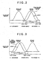
- the valve timing (intake valve timing INVT) of the intake valve 21 is continuously adjusted by the intake valve timing adjustment mechanism 41. Opening timing IVO and closing timing IVC of the intake valve 21 are advanced or retarded by the same crank angle when the valve timing is adjusted. As shown in FIG. 2 , the opening timing IVO and the closing timing IVC of the intake valve 21 are advanced or retarded while a valve opening period IVOA of the intake valve 21 remains constant.
- a full retard position INVTS at which the opening timing NO and the closing timing IVC are the most retarded, is used as the reference.
- the intake valve timing INVT is expressed as an angle of advance ⁇ INVT (hereinafter, referred to as "advance angle ⁇ INVT”) from the full retard position INVTS.
- the exhaust valve timing adjustment mechanism 42 adjusts the rotational phase of a camshaft, which drives the exhaust valve 31, relative to the crankshaft 15 of the engine 10.
- the valve timing (exhaust valve timing EXVT) of the exhaust valve 31 is continuously adjusted by the exhaust valve timing adjustment mechanism 42. Opening timing EVO and closing timing EVC of the exhaust valve 31 are advanced or retarded by the same crank angle when the valve timing is adjusted. As shown in FIG. 3 , the opening timing EVO and the closing timing EVC of the exhaust valve 31 are advanced or retarded while a valve opening period EVOA of the exhaust valve 31 remains constant.
- a full advance position EXVTS at which the opening timing EVO and the closing timing EVC are the most advanced, is used as the reference.
- the exhaust valve timing EXVT is expressed as an angle of retardation ⁇ EXVT (hereinafter, referred to as "retardation angle ⁇ EXVT”) from the full advance position EXVTS.
- the engine 10 is provided with a turbocharger 50 that is driven by the pressure of the exhaust gas discharged from the combustion chamber 12.
- the turbocharger 50 includes a turbine wheel 51 that is arranged in the exhaust pipe 33 and a compressor wheel 52 that is connected to the turbine wheel 51 via a shaft.
- the turbine wheel 51 is rotated by the pressure of the exhaust gas
- the compressor wheel 52 that is connected to the turbine wheel 51 via the shaft is rotated together with the turbine wheel 51. In this way, the air that is taken into the combustion chamber 12 is compressed.
- a bypass passage 53 is connected to the exhaust passage 30 so that the exhaust gas is able to bypass the turbocharger 50.
- a wastegate valve 54 that adjusts the flow passage area of the bypass passage 53 and an actuator 55 that opens and closes the wastegate valve 54.
- the flow rate of the exhaust gas that flows through the bypass passage 53 is adjusted by controlling the opening amount of the wastegate valve 54. In this way, the flow rate of the exhaust gas that flows toward the turbine wheel 51 is adjusted.
- the rotational speed of the turbocharger 50 is adjusted.
- a charging pressure PM that is achieved by the turbocharger 50 of the engine 10 is adjusted by adjusting the rotational speed of the turbocharger 50 in the above-described manner.
- the engine 10 is provided with various sensors that detect the operating state of the engine 10.
- a rotational speed sensor 61 that detects the rotational speed of the crankshaft 15 (hereinafter, referred to as “engine speed NE”) is provided near the crankshaft 15.
- a throttle sensor 62 that detects the opening amount of the throttle valve 24 (hereinafter, referred to as “throttle valve opening amount TA”) is provided near the throttle valve 24.
- An airflow meter 63 that detects the flow rate of the intake air that flows through the intake passage 20 (hereinafter, referred to as “intake air flow rate GA”) is provided upstream of the throttle valve 24.
- a charging pressure sensor 64 that detects the pressure of the intake air (hereinafter, referred to as “charging pressure PM) is provided downstream of the compressor wheel 52.
- a wastegate sensor 65 that detects the opening amount of the wastegate valve 54 (hereinafter, referred to as "wastegate opening amount WA") is provided near the wastegate valve 54.
- An intake valve timing sensor 66 that detects the intake valve timing INVT is provided near the intake valve timing adjustment mechanism 41.
- An exhaust valve timing sensor 67 that detects the exhaust valve timing EXVT is provided near the exhaust valve timing adjustment mechanism 42. Signals indicating detection results from these sensors 61 to 67 are input in an electronic control unit 70 that executes various controls over the engine 10.
- the electronic control unit 70 includes a memory that stores programs and calculation maps which are used to execute various controls and various data that are calculated when the controls are executed.
- the electronic control unit 70 executes, for example, the following controls based on the operating state of the engine 10, which is determined based on the values output from various sensors, for example, the sensors 61 to 67. That is, the electronic control unit 70 calculates the target fuel injection amount and the target fuel injection timing based on the engine operating state, and executes the fuel injection control for controlling the injector 13 based on the target fuel injection amount and the target fuel injection timing.
- the electronic control unit 70 calculates the target ignition timing based on the engine operating state, and executes the ignition timing control for controlling the spark plug 14 based on the target ignition timing.
- the electronic control unit 70 calculates the target throttle valve opening amount based on the engine operating state, and executes the throttle valve control for controlling the throttle motor 25 based on the target throttle valve opening amount.
- the electronic control unit 70 calculates a base advance angle ⁇ INVTb for the intake valve timing INVT based on the engine operating state, and executes the intake valve timing control for controlling the intake valve timing adjustment mechanism 41 based on the base advance angle ⁇ INVTb.
- the electronic control unit 70 calculates a base retardation angle ⁇ EXVTb for the exhaust valve 31 based on the engine operating state, and executes the exhaust valve timing control for controlling the exhaust valve timing adjustment mechanism 42 based on the base retardation angle ⁇ EXVTb.
- the electronic control unit 70 calculates the target opening amount for the wastegate valve 54 based on the engine operating state, and executes the wastegate valve control for controlling the waste gate valve 54 based on the target opening amount.
- the wastegate valve 54 is sometimes kept closed and unable to open. If the wastegate valve 54 is unable to open, the exhaust gas that is supposed to pass through the wastegate valve 54 flows toward the turbine wheel 51 of the turbocharger 50. Therefore, the pressure of the exhaust gas that is applied to the turbine wheel 51 increases, which increases the charging pressure PM. As a result, the power output from the engine excessively increases.
- the electronic control unit 70 determines whether the wastegate valve 54 is unable to open based on the actual opening amount WA of the wastegate valve 54, which is detected by the wastegate sensor 65. In the first embodiment of the invention, it is determined that the wastegate valve 54 is unable to open, if the actual opening amount WA of the wastegate valve 54 is continuously kept smaller than a target opening amount WAT for a predetermined time period. Therefore, the state in which the wastegate valve 54 is unable to open includes the state in which the wastegate valve 54 is fully closed and the state in which the actual opening amount WA of the wastegate valve 54 is continuously kept smaller than the target opening amount WAT. If it is determined that the wastegate valve 54 is unable to open, the valve timing control described below is executed over the variable valve mechanism 40 in such a manner that the pressure of the exhaust gas that is discharged from the combustion chamber 12 is decreased.
- FIG. 4 is a flowchart showing a routine of the valve timing control.
- the routine shown in the flowchart is periodically executed by the electronic control unit 70 during operation of the engine 10.
- the electronic control unit 70 obtains the current engine operating state, and calculates the base advance angle ⁇ INVTb for the intake valve 21 and the base retardation angle ⁇ EXVT for the exhaust valve 31 based on the engine operating state (S101).
- the engine speed NE and an engine load KL are used as the engine operating state.
- a ratio (GA/GAmax) of the current intake air flow rate GA to a maximum intake air flow rate GAmax, which is the maximum value of the intake air flow rate GA that is achievable at the current engine speed NE is used.
- the electronic control unit 70 determines whether the wastegate valve 54 is unable to open (S102). If it is determined that the wastegate valve 54 is unable to open ("YES" in S102), the electronic control unit 70 calculates a target advance angle ⁇ INVTT for the intake valve 21 according to Equation 1 indicated below, and a target retardation angle ⁇ EXVTT for the exhaust valve 31 according to Equation 2 indicated below (S103), after which the routine ends.
- an advance angle correction amount ⁇ KIN and a retardation angle correction amount ⁇ KEX are prescribed fixed values.
- these correction amounts ⁇ KIN and ⁇ KEX may be variably set based on the current charging pressure PM.
- the correction amounts ⁇ KIN and ⁇ KEX may be set to larger values so that the pressure of the exhaust gas that is discharged from the combustion chamber 12 is decreased by a larger amount when the charging pressure PM is high than when the charging pressure PM is low.
- the electronic control unit 70 sets the target advance angle ⁇ INVTT for the intake valve 21 to the base advance angle ⁇ INVTb according to Equation 3 indicated below (S104). In addition, the electronic control unit 70 sets the target retardation angle ⁇ EXVTT for the exhaust valve 31 to the base retardation angle ⁇ EXVTb according to Equation 4 indicated below (S104), after which the routine ends.
- the intake valve timing adjustment mechanism 41 and the exhaust valve timing adjustment mechanism 42 are controlled based on the thus calculated target advance angle ⁇ INVTT and the target retardation angle ⁇ EXVTT, respectively.
- the amount of air that is taken in the combustion chamber 12 via the intake valve 21 in the immediately subsequent combustion stroke is decreased by an amount by which the internal EGR amount is increased.
- the combustion pressure is decreased.
- the amount of exhaust gas that is discharged toward the turbocharger 50 is decreased by an amount of increase in the internal EGR amount.
- the combustion pressure is decreased, and the pressure of the exhaust gas that is discharged from the combustion chamber 12 is decreased.
- Opening timing EVOT (indicated by a solid line) that corresponds to the target retardation angle ⁇ EXVTT for the exhaust valve 31 is retarded relative to the opening timing EVOb that corresponds to the base retardation angle ⁇ EXVTb that is calculated based on the engine operating state. Therefore, the pressure in the combustion chamber 12, which is exhibited when discharge of the exhaust gas from the combustion chamber 12 to the exhaust passage 30 is started, is decreased by an amount that corresponds to an amount by which the opening timing EVOT for the exhaust valve 31 is retarded relative to the opening timing EVOb. Thus, the combustion pressure is decreased, and the pressure of the exhaust gas that is discharged from the combustion chamber 12 is decreased.
- variable valve mechanism 40 is controlled in such a manner that the pressure of the exhaust gas that is discharged from the combustion chamber 12 is decreased.
- the pressure of the exhaust gas that is applied to the turbine wheel 51 of the turbocharger 50 is decreased, and an increase in the charging pressure PM is suppressed. Therefore, it is possible to avoid an excessive increase in the power that is output from the engine when the wastegate valve 54 is unable to open.
- the exhaust valve timing adjustment mechanism 42 is controlled based on the target retardation angle ⁇ EXVTT. Accordingly, the pressure of the exhaust gas that is discharged from the combustion chamber 12 is decreased.
- FIGs. 7 and 8 an internal combustion engine according to a second embodiment of the invention will be described with reference to FIGs. 7 and 8 . Because the structure of the engine 10 is the same as that in the first embodiment of the invention, the description thereof will not be provided below.
- the wastegate valve 54 is kept open and unable to close, the pressure of the exhaust gas that is applied to the turbocharger 50 increases, and the charging pressure PM decreases with an increase in the pressure of the exhaust gas. As a result, the power output from the engine excessively decreases.
- the electronic control unit 70 determines whether the wastegate valve 54 is unable to close based on the actual opening amount WA of the wastegate valve 54 that is detected by the wastegate sensor 65. In the second embodiment of the invention, it is determined that the wastegate valve 54 is unable to close, if the actual opening amount WA of the wastegate valve 54 is continuously kept larger than the target opening amount WAT for a predetermined time period. Therefore, the state in which the wastegate valve 54 is unable to close includes the state in which the wastegate valve 54 is fully open and the state in which the actual opening amount WA of the wastegate valve 54 is continuously kept larger than the target opening amount WAT. If it is determined that the wastegate valve 54 is unable to close, the valve timing control described below is executed over the variable valve mechanism 40 in such a manner that the pressure of the exhaust gas that is discharged from the combustion chamber 12 is increased.
- FIG. 7 is a flowchart showing a routine of the valve timing control.
- the routine in the flowchart is periodically executed by the electronic control unit 70 during operation of the engine 10.
- the electronic control unit 70 obtains the engine operating state, and calculates the base advance angle ⁇ INVTb for the intake valve 21 and the base retardation angle ⁇ EXVT for the exhaust valve 31 based on the engine operating state (S201).
- the electronic control unit 70 determines whether the wastegate valve 54 is unable to close (S202). If it determined that the wastegate valve 54 is unable to close ("YES" in S202), the electronic control unit 70 calculates the target advance angle ⁇ INVTT for the intake valve 21 according to Equation 5 indicated below. In addition, the electronic control unit 70 sets the target retardation angle ⁇ EXVTT for the exhaust valve 31 to the base retardation angle ⁇ EXVTb according to Equation 6 indicated below (S203), after which the routine ends.
- the retardation angle correction amount ⁇ LIN is a prescribed fixed value.
- the retardation angle correction amount ⁇ LIN may be variably set based on, for example, the current charging pressure PM. That is, the retardation angle correction amount ⁇ LIN may be set to a larger value so that the pressure of the exhaust gas that is discharged from the combustion chamber 12 is increased by a larger amount when the charging pressure PM is low than when the charging pressure PM is high.
- the electronic control unit 70 sets the target advance angle ⁇ INVTT for the intake valve 21 to the base advance angle ⁇ INVTb according to Equation 3 indicated below. In addition, the electronic control unit 70 sets the target retardation angle ⁇ EXCTT for the exhaust valve 31 to the base retardation angle ⁇ EXVTb (S204), after which the routine ends.
- the intake valve timing adjustment mechanism 41 and the exhaust valve timing adjustment mechanism 42 are controlled based on the thus calculated target advance angle ⁇ INVTT and the target retardation angle ⁇ EXVTT, respectively.
- the combustion pressure increases, and the pressure of the exhaust gas that is discharged from the combustion chamber 12 increases.
- variable valve mechanism 40 is controlled in such a manner that the pressure of the exhaust gas that is discharged from the combustion chamber 12 is increased.
- the pressure of the exhaust gas that is applied to the turbine wheel 51 of the turbocharger 50 is increased, and a decrease in the charging pressure is suppressed. Accordingly, it is possible to avoid an excessive decrease in the power output from the engine when the wastegate valve 54 is unable to close.
- the configuration for the internal combustion engine according to the invention is not limited to the configurations in the embodiments described above.
- the following configurations may be employed.
- it is determined whether the wastegate valve 54 is unable to open.
- a determination as to whether the actual opening amount WA of the wastegate valve 54 is smaller than the regular opening amount, which is achieved when the wastegate valve 54 operates properly, although the wastegate valve 54 operates may be made in the above-described manner. In this case as well, execution of the valve timing control according to the first embodiment of the invention is effective.
- the wastegate valve 54 it is determined whether the wastegate valve 54 is unable to close.
- a determination as to whether the actual opening amount WA of the wastegate valve 54 is larger than the regular opening amount, which is achieved when the wastegate valve 54 operates properly, although the wastegate valve 54 operates may be made in the above-described manner. In this case as well, execution of the valve timing control according to the second embodiment of the invention is effective.
- the method for determining whether the wastegate valve 54 malfunctions' is not limited to the method described above.
- whether the wastegate valve 54 malfunctions may be determined based on the charging pressure PM.
- the actual opening amount WA of the wastegate valve 54 is larger than the regular opening amount, which is achieved when the wastegate valve 54 operates properly, when the charging pressure PM is continuously kept lower than the target charging pressure for the predetermined time period.
- the valve timing of the intake valve 21 is advanced and the valve timing of the exhaust valve 31 is retarded.
- the valve timing of the exhaust valve 31 is retarded.
- only a correction for advancing the valve timing of the intake valve 21 may be made.
- only a correction for retarding the valve timing of the exhaust valve 31 may be made.
- the closing timing of the exhaust valve 31 is retarded.
- a correction for advancing the closing timing of the exhaust valve 31 may be made.
- the amount of exhaust gas that is introduced into the intake passage 20 without being discharged from the combustion chamber 12 to the exhaust passage 30 is increased by an amount that corresponds to an amount by which the closing timing of the exhaust valve 31 is advanced, that is, an amount by which the exhaust valve 31 is closed earlier.
- a target control amount for the variable valve mechanism 40 may be set with the use of a map that differs from a map which is used when such malfunction has not occurred.
- the cylinder-injection engine 10 is used.
- an internal combustion engine to which the invention is applied is not limited to this.
- the invention may be applied to, for example, a port-injection engine.
- the invention may be applied not only to a gasoline engine but also to a diesel engine.
- variable valve mechanism 40 that adjusts the valve timing of the engine valve is used.
- a variable valve mechanism to which the invention is applied is not limited to this.
- a mechanism that is able to adjusts the valve lift amount may be used.
- variable valve mechanism is controlled in such a manner that the pressure of the exhaust gas that is discharged from the combustion chamber 12 approaches the pressure of the exhaust gas, which is exhibited when such malfunction has not occurred.
Abstract
Description
- The invention relates to an internal combustion engine that includes a turbocharger which is driven by exhaust gas and which compresses air that is taken into a combustion chamber, a bypass passage through which the exhaust gas bypasses the turbocharger when flowing through an exhaust passage, and a wastegate valve which is provided in the bypass passage and which adjusts a flow passage area of the bypass passage, and a method for controlling the internal combustion engine.
- An internal combustion engine of the above-mentioned type is described in, for example, Japanese Patent Application Publication No.
2004-19449 JP-A-2004-19449 JP-A-2004-19449 - However, if the actual opening amount of the wastegate valve deviates from the regular opening amount of the wastegate valve, which is achieved when it operates properly, it is difficult to control the wastegate valve accurately. As a result, it is not possible to accurately control the pressure of the exhaust gas that is applied to the turbine wheel of the turbocharger, that is, it is not possible to accurately control the charging pressure. This creates a possibility that the power output from the engine will be excessively increased or excessively decreased.
- The invention provides an internal combustion engine and an engine control method with which excessive fluctuation of the power output from the internal combustion engine is avoided when an actual opening amount of a wastegate valve deviates from a regular opening amount that is achieved when the wastegate valve operates properly.
- A first aspect of the invention relates to an internal combustion engine that includes a turbocharger which is driven by exhaust gas and which compresses air that is taken into a combustion chamber, a bypass passage through which the exhaust gas bypasses the turbocharger when flowing through an exhaust passage, and a wastegate valve which is provided in the bypass passage and which adjusts the flow passage area of the bypass passage, The internal combustion engine according to the first aspect of the invention further includes: a variable valve mechanism that adjusts the manner of opening and closing an engine valve; determination means for determining whether the actual opening amount of the wastegate valve deviates from the regular opening amount which is achieved when the wastegate valve operates properly; and control means for controlling the variable valve mechanism. When the determination means determines that the actual opening amount of the wastegate valve deviates from the regular opening amount, the control means controls the variable valve mechanism in such a manner that the pressure of the exhaust gas that is discharged from the combustion chamber approaches the pressure of the exhaust gas which is exhibited when the actual opening amount of the wastegate valve agrees with the regular opening amount.
- According to the first aspect of the invention, when it is determined that the actual opening amount of the wastegate valve deviates from the regular opening amount, the variable valve mechanism is controlled in such a manner that the pressure of the exhaust gas that is discharged from the combustion chamber approaches the pressure of the exhaust gas which is exhibited when the actual opening amount of the wastegate valve agrees with the regular opening amount. Accordingly, when the actual opening amount of the wastegate valve deviates from the regular opening amount, excessive fluctuation of the power output from the engine is avoided.
- In the internal combustion engine according to the first aspect of the invention, when the determination means determines that the actual opening amount of the wastegate valve is smaller than the regular opening amount, the control means may control the variable valve mechanism in such a manner that the pressure of the exhaust gas that is discharged from the combustion chamber is decreased.
- The pressure of the exhaust gas that is applied to the turbocharger is higher and the charging pressure is higher when the actual opening amount of the wastegate valve is smaller than the regular opening amount than when the actual opening amount of the wastegate valve agrees with the regular opening amount. As a result, the power output from the engine excessively increases.
- However, with the configuration described above, when it is determined that the actual opening amount of the wastegate valve is smaller than the regular opening amount, the variable valve mechanism is controlled in such a manner that the pressure of the exhaust gas that is discharged from the combustion chamber is decreased. Thus, the pressure of the exhaust gas that is applied to the turbocharger is decreased, and an increase in the charging pressure is suppressed. Accordingly, when the actual opening amount of the wastegate valve is smaller than the regular opening amount, an excessive increase in the power output from the engine is avoided.
- In the internal combustion engine that has the above-described configuration, when it is not determined that the actual opening amount of the wastegate valve is smaller than the regular opening amount, the control means may control the variable valve mechanism based on a target manner of opening and closing the engine valve, which is calculated based on an engine operating state. On the other hand, when it is determined that the actual opening amount of the wastegate valve is smaller than the regular opening amount, the control means may correct the target manner of opening and closing the engine valve in such a manner that the pressure of the exhaust gas that is discharged from the combustion chamber is decreased, and may control the variable valve mechanism based on the corrected target manner of opening and closing the engine valve.
- In the internal combustion engine that has the above-described configuration, the variable valve mechanism may be an intake valve timing adjustment mechanism that adjusts closing timing of an intake valve, which is used as the manner of opening and closing the engine valve. When it is determined that the actual opening amount of the wastegate valve is smaller than the regular opening amount, the control means may advance the closing timing of the intake valve relative to target closing timing that is calculated based on the engine operating state, and may control the intake valve timing adjustment mechanism based on the corrected target closing timing.
- With the configuration described above, the amount of air that is taken in the combustion chamber via the intake valve is decreased by an amount that corresponds to an amount by which the closing timing of the intake valve is advanced relative to target closing timing, that is, an amount by which the intake valve is closed earlier than the target closing timing. Thus, the combustion pressure is decreased, and the pressure of the exhaust gas that is discharged from the combustion chamber is decreased.
- In the internal combustion engine that has the above-described configuration, the variable valve mechanism may be an exhaust valve timing adjustment mechanism that adjusts closing timing of an exhaust valve, which is used as the manner of opening and closing the engine valve. When it is determined that the actual opening amount of the wastegate valve is smaller than the regular opening amount, the control means may retard the closing timing of the exhaust valve relative to target closing timing that is calculated based on the engine operating state and may control the exhaust valve timing adjustment mechanism based on the corrected target closing timing, thereby increasing a valve overlap period in which the exhaust valve and the intake valve are both open.
- With the configuration described above, the amount of exhaust gas that is returned to the combustion chamber, which is part of the exhaust gas discharged from the combustion chamber into the exhaust passage, that is, the internal EGR amount, is increased by an amount that corresponds to an amount by which a valve overlap period is increased due to retardation of the closing timing of the exhaust valve. Thus, the amount of air that is taken in the combustion chamber via the intake valve in the immediately subsequent combustion stroke is decreased by an amount by which the internal EGR amount is increased. As a result, the combustion pressure is decreased. The amount of exhaust gas that is discharged toward the turbocharger is decreased by an amount of increase in the internal EGR amount. Thus, the pressure of the exhaust gas that is discharged from the combustion chamber is decreased.
- In the internal combustion engine that has the above-described configuration, the variable valve mechanism may be an exhaust valve timing adjustment mechanism that adjusts closing timing of an exhaust valve, which is used as the manner of opening and closing the engine valve. When it is determined that the actual opening amount of the wastegate valve is smaller than the regular opening amount, the control means may advance closing timing of the exhaust valve relative to target closing timing that is calculated based on the engine operating state, and may control the exhaust valve timing adjustment mechanism based on the corrected target closing timing.
- With the configuration described above, the amount of exhaust gas that is introduced into the intake passage without being discharged from the combustion chamber to the exhaust passage is increased by an amount that corresponds to an amount by which the closing timing of the exhaust valve is advanced relative to the target closing timing, that is, an amount by which the exhaust valve is closed earlier than the target closing timing. Thus, it is possible to decrease the amount of air taken in the combustion chamber via the intake valve in the immediately subsequent combustion stroke by an amount of increase in the exhaust gas. Accordingly, the combustion pressure is decreased. As a result, it is possible to decrease the pressure of the exhaust gas that is discharged from the combustion chamber.
- In the internal combustion engine according to the first aspect of the invention, when the determination means determines that the actual opening amount of the wastegate valve is larger than the regular opening amount, the control means may control the variable valve mechanism in such a manner that the pressure of the exhaust gas that is discharged from the combustion chamber is increased.
- The pressure of the exhaust gas that is applied to the turbocharger is lower and the charging pressure is lower when the actual opening amount of the wastegate valve is larger than the regular opening amount than when the actual opening amount of the wastegate valve agrees with the regular opening amount. As a result, the power output from the engine excessively decreases.
- However, with the configuration described above, when it is determined that the actual opening amount of the wastegate valve is larger than the regular opening amount, the variable valve mechanism is controlled in such a manner that the pressure of the exhaust gas that is discharged from the combustion chamber is increased. Thus, the pressure of the exhaust gas that is applied to the turbocharger is increased, and a decrease in the charging pressure is suppressed. Accordingly, when the actual opening amount of the wastegate valve is larger than the regular opening amount, an excessive decrease in the power output from the engine is avoided.
- In the above-described configuration, when it is not determined that the actual opening amount of the wastegate valve is larger than the regular opening amount, the control means may control the variable valve mechanism based on a target manner of opening and closing the engine valve, which is calculated based on the engine operating state.. On the other hand, when it is determined that the actual opening amount of the wastegate valve is larger than the regular opening amount, the control means may correct the target manner of opening and closing the engine valve in such a manner that the pressure of the exhaust gas that is discharged from the combustion chamber is increased, and may control the variable valve mechanism based on the corrected target manner of opening and closing the engine valve.
- In the internal combustion engine that has the above-described configuration, the variable valve mechanism may be an intake valve timing adjustment mechanism that adjusts closing timing of an intake valve, which is used as the manner of opening and closing the engine valve. When it is determined that the actual opening amount of the wastegate valve is larger than the regular opening amount, the control means may retard the closing timing of the intake valve relative to target closing timing, which is calculated based on the engine operating state, and may control the intake valve timing adjustment mechanism based on the corrected target closing timing.
- With the configuration described above, the amount of air that is taken into the combustion chamber via the intake valve is increased by an amount that corresponds to an amount by which the closing timing of the intake valve is retarded relative to the target closing timing, that is, an amount by which the intake valve is closed later than the target closing timing. Thus, the combustion pressure is increased, and the pressure of the exhaust gas that is discharged from the combustion chamber is increased.
A second aspect of the invention relates to a method for controlling an internal combustion engine that includes a turbocharger which is driven by exhaust gas and which compresses air that is taken into a combustion chamber, a bypass passage through which the exhaust gas bypasses the turbocharger when flowing through an exhaust passage, and a wastegate valve which is provided in the bypass passage and which adjusts the flow passage area of the bypass passage. According to the method, it is determined whether the actual opening amount of the wastegate valve deviates from the regular opening amount which is achieved when the waste gate valve operates properly. When it is determined that the actual opening amount of the wastegate valve deviates from the regular opening amount, the manner of opening and closing an engine valve is adjusted in such a manner that the pressure of the exhaust gas that is discharged from the combustion chamber approaches the pressure of the exhaust gas which is exhibited when the actual opening amount of the wastegate valve agrees with the regular opening amount. - The foregoing and further features and advantages of the invention will become apparent from the following description of example embodiments with reference to the accompanying drawings, wherein the same or corresponding portions will be denoted by the same reference numerals and wherein:
-
FIG. 1 is a view schematically showing the structure of an internal combustion engine according to a first embodiment of the invention; -
FIG. 2 is a graph for describing the valve timing of an intake valve according to the first embodiment of the invention; -
FIG. 3 is a graph for describing the valve timing of an exhaust valve according to the first embodiment of the invention; -
FIG 4 is a flowchart showing a routine of valve timing control according to the first embodiment of the invention; -
FIG. 5 is a graph for describing the valve timing of the intake valve according to the first embodiment of the invention; -
FIG 6 is a graph for describing the valve timing of the exhaust valve according to the first embodiment of the invention; -
FIG 7 is a flowchart showing a routine of valve timing control that is executed over an internal combustion engine according to a second embodiment of the invention; and -
FIG. 8 is a graph for describing the valve timing of the intake valve according to the second embodiment of the invention. - Hereafter, a first embodiment of the invention will be described with reference to
FIGs. 1 to 6 . In the first embodiment, the invention is applied to an in-vehicle cylinder-injection gasoline engine (hereinafter, referred to as "engine 10"). -
FIG. 1 schematically shows the structure of theengine 10. Acylinder 11 of theengine 10 is provided with aninjector 13 that injects fuel directly into acombustion chamber 12 and aspark plug 14 that ignites an air-fuel mixture formed of air and the fuel injected from theinjector 13. Anintake passage 20 and anexhaust passage 30 are connected to thecombustion chamber 12 of theengine 10. Thecylinder 11 of theengine 10 is provided with an intake valve 21 that changes the state of communication between thecombustion chamber 12 and theintake passage 20 and an exhaust valve 31 that changes the state of communication between thecombustion chamber 12 and theexhaust passage 30. - The
intake passage 20 is defined by anintake port 22 that is connected to thecombustion chamber 12 and anintake pipe 23 that is connected to an upstream-side portion of theintake port 22. A throttle valve 24 that adjusts the flow passage area of theintake pipe 23 and a throttle motor 25 that opens and closes the throttle valve 24 are provided in theintake pipe 23. The flow rate of the intake air that is supplied to thecombustion chamber 12 through theintake passage 20 is controlled based on the opening amount of the throttle valve 24. - The
exhaust passage 30 is defined by anexhaust port 32 that is connected to thecombustion chamber 12 and anexhaust pipe 33 that is connected to a downstream-side portion of theexhaust port 32. Theengine 10 is provided with avariable valve mechanism 40 that adjusts the manner of opening and closing the engine valves (the intake valve 21 and the exhaust valve 31). Thevariable valve mechanism 40 includes an intake valvetiming adjustment mechanism 41 that adjusts the valve timing of the intake valve 21 and an exhaust valvetiming adjustment mechanism 42 that adjusts the valve timing of the exhaust valve 31. - The intake valve
timing adjustment mechanism 41 adjusts the rotational phase of a camshaft, which drives the intake valve 21, relative to acrankshaft 15 of theengine 10. The valve timing (intake valve timing INVT) of the intake valve 21 is continuously adjusted by the intake valvetiming adjustment mechanism 41. Opening timing IVO and closing timing IVC of the intake valve 21 are advanced or retarded by the same crank angle when the valve timing is adjusted. As shown inFIG. 2 , the opening timing IVO and the closing timing IVC of the intake valve 21 are advanced or retarded while a valve opening period IVOA of the intake valve 21 remains constant. In the first embodiment of the invention, a full retard position INVTS, at which the opening timing NO and the closing timing IVC are the most retarded, is used as the reference. The intake valve timing INVT is expressed as an angle of advance ΔINVT (hereinafter, referred to as "advance angle ΔINVT") from the full retard position INVTS. - The exhaust valve
timing adjustment mechanism 42 adjusts the rotational phase of a camshaft, which drives the exhaust valve 31, relative to thecrankshaft 15 of theengine 10. The valve timing (exhaust valve timing EXVT) of the exhaust valve 31 is continuously adjusted by the exhaust valvetiming adjustment mechanism 42. Opening timing EVO and closing timing EVC of the exhaust valve 31 are advanced or retarded by the same crank angle when the valve timing is adjusted. As shown inFIG. 3 , the opening timing EVO and the closing timing EVC of the exhaust valve 31 are advanced or retarded while a valve opening period EVOA of the exhaust valve 31 remains constant. In the first embodiment of the invention, a full advance position EXVTS, at which the opening timing EVO and the closing timing EVC are the most advanced, is used as the reference. The exhaust valve timing EXVT is expressed as an angle of retardation ΔEXVT (hereinafter, referred to as "retardation angle ΔEXVT") from the full advance position EXVTS. - The
engine 10 is provided with aturbocharger 50 that is driven by the pressure of the exhaust gas discharged from thecombustion chamber 12. Theturbocharger 50 includes aturbine wheel 51 that is arranged in theexhaust pipe 33 and acompressor wheel 52 that is connected to theturbine wheel 51 via a shaft. When theturbine wheel 51 is rotated by the pressure of the exhaust gas, thecompressor wheel 52 that is connected to theturbine wheel 51 via the shaft is rotated together with theturbine wheel 51. In this way, the air that is taken into thecombustion chamber 12 is compressed. - A
bypass passage 53 is connected to theexhaust passage 30 so that the exhaust gas is able to bypass theturbocharger 50. In thebypass passage 53, there are provided a wastegate valve 54 that adjusts the flow passage area of thebypass passage 53 and anactuator 55 that opens and closes the wastegate valve 54. The flow rate of the exhaust gas that flows through thebypass passage 53 is adjusted by controlling the opening amount of the wastegate valve 54. In this way, the flow rate of the exhaust gas that flows toward theturbine wheel 51 is adjusted. As a result, the rotational speed of theturbocharger 50 is adjusted. A charging pressure PM that is achieved by theturbocharger 50 of theengine 10 is adjusted by adjusting the rotational speed of theturbocharger 50 in the above-described manner. - The
engine 10 is provided with various sensors that detect the operating state of theengine 10. Arotational speed sensor 61 that detects the rotational speed of the crankshaft 15 (hereinafter, referred to as "engine speed NE") is provided near thecrankshaft 15. A throttle sensor 62 that detects the opening amount of the throttle valve 24 (hereinafter, referred to as "throttle valve opening amount TA") is provided near the throttle valve 24. Anairflow meter 63 that detects the flow rate of the intake air that flows through the intake passage 20 (hereinafter, referred to as "intake air flow rate GA") is provided upstream of the throttle valve 24. A chargingpressure sensor 64 that detects the pressure of the intake air (hereinafter, referred to as "charging pressure PM) is provided downstream of thecompressor wheel 52. A wastegate sensor 65 that detects the opening amount of the wastegate valve 54 (hereinafter, referred to as "wastegate opening amount WA") is provided near the wastegate valve 54. An intakevalve timing sensor 66 that detects the intake valve timing INVT is provided near the intake valvetiming adjustment mechanism 41. An exhaustvalve timing sensor 67 that detects the exhaust valve timing EXVT is provided near the exhaust valvetiming adjustment mechanism 42. Signals indicating detection results from thesesensors 61 to 67 are input in anelectronic control unit 70 that executes various controls over theengine 10. - The
electronic control unit 70 includes a memory that stores programs and calculation maps which are used to execute various controls and various data that are calculated when the controls are executed. Theelectronic control unit 70 executes, for example, the following controls based on the operating state of theengine 10, which is determined based on the values output from various sensors, for example, thesensors 61 to 67. That is, theelectronic control unit 70 calculates the target fuel injection amount and the target fuel injection timing based on the engine operating state, and executes the fuel injection control for controlling theinjector 13 based on the target fuel injection amount and the target fuel injection timing. Theelectronic control unit 70 calculates the target ignition timing based on the engine operating state, and executes the ignition timing control for controlling thespark plug 14 based on the target ignition timing. Theelectronic control unit 70 calculates the target throttle valve opening amount based on the engine operating state, and executes the throttle valve control for controlling the throttle motor 25 based on the target throttle valve opening amount. Theelectronic control unit 70 calculates a base advance angle ΔINVTb for the intake valve timing INVT based on the engine operating state, and executes the intake valve timing control for controlling the intake valvetiming adjustment mechanism 41 based on the base advance angle ΔINVTb. Theelectronic control unit 70 calculates a base retardation angle ΔEXVTb for the exhaust valve 31 based on the engine operating state, and executes the exhaust valve timing control for controlling the exhaust valvetiming adjustment mechanism 42 based on the base retardation angle ΔEXVTb. Theelectronic control unit 70 calculates the target opening amount for the wastegate valve 54 based on the engine operating state, and executes the wastegate valve control for controlling the waste gate valve 54 based on the target opening amount. - In the
engine 10, the wastegate valve 54 is sometimes kept closed and unable to open. If the wastegate valve 54 is unable to open, the exhaust gas that is supposed to pass through the wastegate valve 54 flows toward theturbine wheel 51 of theturbocharger 50. Therefore, the pressure of the exhaust gas that is applied to theturbine wheel 51 increases, which increases the charging pressure PM. As a result, the power output from the engine excessively increases. - Therefore, in the first embodiment of the invention, the
electronic control unit 70 determines whether the wastegate valve 54 is unable to open based on the actual opening amount WA of the wastegate valve 54, which is detected by the wastegate sensor 65. In the first embodiment of the invention, it is determined that the wastegate valve 54 is unable to open, if the actual opening amount WA of the wastegate valve 54 is continuously kept smaller than a target opening amount WAT for a predetermined time period. Therefore, the state in which the wastegate valve 54 is unable to open includes the state in which the wastegate valve 54 is fully closed and the state in which the actual opening amount WA of the wastegate valve 54 is continuously kept smaller than the target opening amount WAT. If it is determined that the wastegate valve 54 is unable to open, the valve timing control described below is executed over thevariable valve mechanism 40 in such a manner that the pressure of the exhaust gas that is discharged from thecombustion chamber 12 is decreased. - Next, the valve timing control will be described with reference to
FIG. 4. FIG. 4 is a flowchart showing a routine of the valve timing control. The routine shown in the flowchart is periodically executed by theelectronic control unit 70 during operation of theengine 10. - In this routine, the
electronic control unit 70 obtains the current engine operating state, and calculates the base advance angle ΔINVTb for the intake valve 21 and the base retardation angle ΔEXVT for the exhaust valve 31 based on the engine operating state (S101). In this routine, the engine speed NE and an engine load KL are used as the engine operating state. As the engine load KL, a ratio (GA/GAmax) of the current intake air flow rate GA to a maximum intake air flow rate GAmax, which is the maximum value of the intake air flow rate GA that is achievable at the current engine speed NE, is used. - Next, the
electronic control unit 70 determines whether the wastegate valve 54 is unable to open (S102). If it is determined that the wastegate valve 54 is unable to open ("YES" in S102), theelectronic control unit 70 calculates a target advance angle ΔINVTT for the intake valve 21 according to Equation 1 indicated below, and a target retardation angle ΔEXVTT for the exhaust valve 31 according to Equation 2 indicated below (S103), after which the routine ends.

Here, an advance angle correction amount ΔKIN and a retardation angle correction amount ΔKEX are prescribed fixed values. Alternatively, these correction amounts ΔKIN and ΔKEX may be variably set based on the current charging pressure PM. The correction amounts ΔKIN and ΔKEX may be set to larger values so that the pressure of the exhaust gas that is discharged from thecombustion chamber 12 is decreased by a larger amount when the charging pressure PM is high than when the charging pressure PM is low. - On the other hand, it is determined that the wastegate valve 54 is able to open ("NO" in S102), the
electronic control unit 70 sets the target advance angle ΔINVTT for the intake valve 21 to the base advance angle ΔINVTb according to Equation 3 indicated below (S104). In addition, theelectronic control unit 70 sets the target retardation angle ΔEXVTT for the exhaust valve 31 to the base retardation angle ΔEXVTb according to Equation 4 indicated below (S104), after which the routine ends.

The intake valvetiming adjustment mechanism 41 and the exhaust valvetiming adjustment mechanism 42 are controlled based on the thus calculated target advance angle ΔINVTT and the target retardation angle ΔEXVTT, respectively. - Next, with reference to
FIG. 5 , description will be provided concerning the effect that is obtained by advancing the valve timing of the intake valve 21 when it is determined that the wastegate valve 54 is unable to open. - Closing timing IVCT (indicated by a solid line) that corresponds to the target advance angle ΔINVTT (=ΔINVTb + ΔKIN) for the intake valve 21 is advanced relative to closing timing IVCb (indicated by a dashed line) that corresponds to the base advance angle ΔINVTb that is calculated based on the engine operating state. Therefore, the amount of air that is taken in the
combustion chamber 12 via the intake valve 21 is decreased by an amount that corresponds to an amount by which the closing timing IVCT for the intake valve 21 is advanced relative to the closing timing IVCb. As a result, the combustion pressure decreases, and the pressure of the exhaust gas that is discharged from thecombustion chamber 12 is decreased. - Next, with reference to
FIG. 6 , description will be provided concerning the effect that is obtained by retarding the valve timing of the exhaust valve 31 when it is determined that the wastegate valve 54 is unable to open. - Closing timing EVCT (indicated by a solid line) that corresponds to the target retardation angle ΔEXVTT (= ΔEXVTb + ΔKEX) for the exhaust valve 31 is retarded relative to closing timing EVCb that corresponds to the base retardation angle ΔEXVTb that is calculated based on the engine operating state. Therefore, the amount of exhaust gas that is returned to the
combustion chamber 12, which is part of the exhaust gas discharged from thecombustion chamber 12 into theexhaust passage 30, that is, the internal EGR amount, is increased by an amount that corresponds to an amount by which a valve overlap period, in which the exhaust valve 31 and the intake valve 21 are both open, is increased. Thus, the amount of air that is taken in thecombustion chamber 12 via the intake valve 21 in the immediately subsequent combustion stroke is decreased by an amount by which the internal EGR amount is increased. As a result, the combustion pressure is decreased. The amount of exhaust gas that is discharged toward theturbocharger 50 is decreased by an amount of increase in the internal EGR amount. Thus, the combustion pressure is decreased, and the pressure of the exhaust gas that is discharged from thecombustion chamber 12 is decreased. - Opening timing EVOT (indicated by a solid line) that corresponds to the target retardation angle ΔEXVTT for the exhaust valve 31 is retarded relative to the opening timing EVOb that corresponds to the base retardation angle ΔEXVTb that is calculated based on the engine operating state. Therefore, the pressure in the
combustion chamber 12, which is exhibited when discharge of the exhaust gas from thecombustion chamber 12 to theexhaust passage 30 is started, is decreased by an amount that corresponds to an amount by which the opening timing EVOT for the exhaust valve 31 is retarded relative to the opening timing EVOb. Thus, the combustion pressure is decreased, and the pressure of the exhaust gas that is discharged from thecombustion chamber 12 is decreased. - With the internal combustion engine according to the first embodiment of the invention described above, the following effects are obtained. 1) If it is determined that the wastegate valve 54 is unable to open, the
variable valve mechanism 40 is controlled in such a manner that the pressure of the exhaust gas that is discharged from thecombustion chamber 12 is decreased. Thus, the pressure of the exhaust gas that is applied to theturbine wheel 51 of theturbocharger 50 is decreased, and an increase in the charging pressure PM is suppressed. Therefore, it is possible to avoid an excessive increase in the power that is output from the engine when the wastegate valve 54 is unable to open. - 2) If it is determined that the wastegate valve 54 is unable to open, the target advance angle ΔINVTT ( = ΔINVTb + ΔKIN) is set to the sum of the base advance angle ΔINVTb for the intake valve 21, which is calculated based on the engine operating state, and the advance angle correction amount ΔKIN. Then, the intake valve
timing adjustment mechanism 41 is controlled based on the target advance angle ΔINVTT. Thus, the combustion pressure is decreased, and the pressure of the exhaust gas that is discharged from the combustion chamber is decreased. - 3) If it is determined that the wastegate valve 54 is unable to open, the target retardation angle ΔEXVTT ( = ΔEXVTb + ΔKEX) is set to the sum of the base retardation angle ΔEXVTb for the exhaust valve 31, which is calculated based on the engine operating state, and the retardation angle correction amount ΔKEX, so that the valve overlap period in which the exhaust valve 31 and the intake valve 21 are both open is increased. Then, the exhaust valve
timing adjustment mechanism 42 is controlled based on the target retardation angle ΔEXVTT. Accordingly, the pressure of the exhaust gas that is discharged from thecombustion chamber 12 is decreased. - Hereafter, an internal combustion engine according to a second embodiment of the invention will be described with reference to
FIGs. 7 and8 . Because the structure of theengine 10 is the same as that in the first embodiment of the invention, the description thereof will not be provided below. - If the wastegate valve 54 is kept open and unable to close, the pressure of the exhaust gas that is applied to the
turbocharger 50 increases, and the charging pressure PM decreases with an increase in the pressure of the exhaust gas. As a result, the power output from the engine excessively decreases. - Therefore, according to the second embodiment of the invention, the
electronic control unit 70 determines whether the wastegate valve 54 is unable to close based on the actual opening amount WA of the wastegate valve 54 that is detected by the wastegate sensor 65. In the second embodiment of the invention, it is determined that the wastegate valve 54 is unable to close, if the actual opening amount WA of the wastegate valve 54 is continuously kept larger than the target opening amount WAT for a predetermined time period. Therefore, the state in which the wastegate valve 54 is unable to close includes the state in which the wastegate valve 54 is fully open and the state in which the actual opening amount WA of the wastegate valve 54 is continuously kept larger than the target opening amount WAT. If it is determined that the wastegate valve 54 is unable to close, the valve timing control described below is executed over thevariable valve mechanism 40 in such a manner that the pressure of the exhaust gas that is discharged from thecombustion chamber 12 is increased. - Next, the valve timing control will be described with reference to
FIG 7. FIG. 7 is a flowchart showing a routine of the valve timing control. The routine in the flowchart is periodically executed by theelectronic control unit 70 during operation of theengine 10. - In this routine as well, the
electronic control unit 70 obtains the engine operating state, and calculates the base advance angle ΔINVTb for the intake valve 21 and the base retardation angle ΔEXVT for the exhaust valve 31 based on the engine operating state (S201). - Next, the
electronic control unit 70 determines whether the wastegate valve 54 is unable to close (S202). If it determined that the wastegate valve 54 is unable to close ("YES" in S202), theelectronic control unit 70 calculates the target advance angle ΔINVTT for the intake valve 21 according to Equation 5 indicated below. In addition, theelectronic control unit 70 sets the target retardation angle ΔEXVTT for the exhaust valve 31 to the base retardation angle ΔEXVTb according to Equation 6 indicated below (S203), after which the routine ends.

Here, the retardation angle correction amount ΔLIN is a prescribed fixed value. Alternatively, the retardation angle correction amount ΔLIN may be variably set based on, for example, the current charging pressure PM. That is, the retardation angle correction amount ΔLIN may be set to a larger value so that the pressure of the exhaust gas that is discharged from thecombustion chamber 12 is increased by a larger amount when the charging pressure PM is low than when the charging pressure PM is high. - On the other hand, if it is determined that the wastegate valve is able to close ("NO" in S202), the
electronic control unit 70 sets the target advance angle ΔINVTT for the intake valve 21 to the base advance angle ΔINVTb according to Equation 3 indicated below. In addition, theelectronic control unit 70 sets the target retardation angle ΔEXCTT for the exhaust valve 31 to the base retardation angle ΔEXVTb (S204), after which the routine ends. - The intake valve
timing adjustment mechanism 41 and the exhaust valvetiming adjustment mechanism 42 are controlled based on the thus calculated target advance angle ΔINVTT and the target retardation angle ΔEXVTT, respectively. - Next, with reference to
FIG. 8 , description will be provided concerning the effect that is obtained by retarding the valve timing of the intake valve 21 when it is determined that the wastegate valve 54 is unable to close. - The closing timing IVCT (indicated by a solid line) that corresponds to the target advance angle ΔINVTT (= ΔINVTb - ΔLIN) for the intake valve 21 is retarded relative to the closing timing IVCb (indicated by a dashed line) that corresponds to the base advance angle ΔINVTb that is calculated based on the engine operating state. Therefore, the amount of air that is taken in the
combustion chamber 12 via the intake valve 21 is increased by an amount that corresponds to an amount by which the closing timing IVCT for the intake valve 21 is retarded relative to the closing timing IVCb. Thus, the combustion pressure increases, and the pressure of the exhaust gas that is discharged from thecombustion chamber 12 increases. - With the internal combustion engine according to the second embodiment of the invention, the following effects are obtained. 1) If it is determined that the wastegate valve 54 is unable to close, the
variable valve mechanism 40 is controlled in such a manner that the pressure of the exhaust gas that is discharged from thecombustion chamber 12 is increased. Thus, the pressure of the exhaust gas that is applied to theturbine wheel 51 of theturbocharger 50 is increased, and a decrease in the charging pressure is suppressed. Accordingly, it is possible to avoid an excessive decrease in the power output from the engine when the wastegate valve 54 is unable to close. - 2) If it is determined that the wastegate valve 54 is unable to close, the target advance angle ΔINVTT ( = ΔINVTb - ΔLIN) is set to a value obtained by subtracting the retardation angle correction amount ΔLIN from the base advance angle ΔINVTb for the intake valve 21 that is calculated based on the engine operating state. Then, the intake valve
timing adjustment mechanism 41 is controlled based on the target advance angle ΔINVTT. Thus, the combustion pressure is increased, and the pressure of the exhaust gas that is discharged from the combustion chamber is increased. - The configuration for the internal combustion engine according to the invention is not limited to the configurations in the embodiments described above. For example, the following configurations may be employed. In the first embodiment of the invention, it is determined whether the wastegate valve 54 is unable to open. Alternatively, a determination as to whether the actual opening amount WA of the wastegate valve 54 is smaller than the regular opening amount, which is achieved when the wastegate valve 54 operates properly, although the wastegate valve 54 operates may be made in the above-described manner. In this case as well, execution of the valve timing control according to the first embodiment of the invention is effective.
- In the second embodiment of the invention, it is determined whether the wastegate valve 54 is unable to close. Alternatively, a determination as to whether the actual opening amount WA of the wastegate valve 54 is larger than the regular opening amount, which is achieved when the wastegate valve 54 operates properly, although the wastegate valve 54 operates may be made in the above-described manner. In this case as well, execution of the valve timing control according to the second embodiment of the invention is effective.
- In the embodiments of the invention described above, it is determined whether the actual opening amount WA of the wastegate valve 54 deviates from the regular opening amount, which is achieved when the wastegate valve 54 operates properly, by comparing the actual opening amount WA of the wastegate valve 54 with the target opening amount WAT. However, the method for determining whether the wastegate valve 54 malfunctions' is not limited to the method described above. For example, whether the wastegate valve 54 malfunctions may be determined based on the charging pressure PM. In this case, it may be determined that the actual opening amount WA of the wastegate valve 54 is smaller than the regular opening amount, which is achieved when the wastegate valve 54 operates properly, when the charging pressure PM is continuously kept higher than a target charging pressure for a predetermined time period. It may be determined that the actual opening amount WA of the wastegate valve 54 is larger than the regular opening amount, which is achieved when the wastegate valve 54 operates properly, when the charging pressure PM is continuously kept lower than the target charging pressure for the predetermined time period.
- In the first embodiment of the invention, if it is determined that the wastegate valve 54 is unable to open, the valve timing of the intake valve 21 is advanced and the valve timing of the exhaust valve 31 is retarded. Alternatively, only a correction for advancing the valve timing of the intake valve 21 may be made. Further alternatively, only a correction for retarding the valve timing of the exhaust valve 31 may be made.
- In the first embodiment of the invention, if it is determined that the wastegate valve 54 is unable to open, the closing timing of the exhaust valve 31 is retarded. Alternatively, a correction for advancing the closing timing of the exhaust valve 31 may be made. In this case, the amount of exhaust gas that is introduced into the
intake passage 20 without being discharged from thecombustion chamber 12 to theexhaust passage 30 is increased by an amount that corresponds to an amount by which the closing timing of the exhaust valve 31 is advanced, that is, an amount by which the exhaust valve 31 is closed earlier. Thus, it is possible to decrease the amount of air taken in thecombustion chamber 12 via the intake valve 21 in the immediately subsequent combustion stroke by an amount of increase in the exhaust gas. Accordingly, the combustion pressure is decreased. As a result, it is possible to decrease the pressure of the exhaust gas that is discharged from thecombustion chamber 12. - In the embodiments of the invention described above, if it is determined that the actual opening amount WA of the wastegate valve 54 deviates from the regular opening amount, which is achieved when the wastegate valve 54 operates properly, corrections are made to the base advance angle ΔINVTb for the intake valve 21 and the base retardation angle ΔEXVTb for the exhaust valve 31, which are calculated based on the engine operating state on an as-required basis. Then, the
variable valve mechanism 40 is controlled based on the target advance angle ΔINVTT for the intake valve 21 and the target retardation angle ΔEXVTT for the exhaust valve 31 which are calculated through the corrections. However, another control may be executed instead of the corrections described above. For example, if it is determined that the actual opening amount WA of the wastegate valve 54 deviates from the regular opening amount, which is achieved when the wastegate valve 54 operates properly, a target control amount for thevariable valve mechanism 40 may be set with the use of a map that differs from a map which is used when such malfunction has not occurred. - In the embodiments of the invention described above, the cylinder-
injection engine 10 is used. However, an internal combustion engine to which the invention is applied is not limited to this. The invention may be applied to, for example, a port-injection engine. The invention may be applied not only to a gasoline engine but also to a diesel engine. - In the embodiments of the invention described above, the
variable valve mechanism 40 that adjusts the valve timing of the engine valve is used. However, a variable valve mechanism to which the invention is applied is not limited to this. For example, a mechanism that is able to adjusts the valve lift amount may be used. - The invention may be implemented in various other embodiments. According to the invention, if it is determined that the actual opening amount WA of the wastegate valve 54 deviates from the regular opening amount, which is achieved when the wastegate valve 54 operates properly, the variable valve mechanism is controlled in such a manner that the pressure of the exhaust gas that is discharged from the
combustion chamber 12 approaches the pressure of the exhaust gas, which is exhibited when such malfunction has not occurred. - While the invention has been described with reference to the example embodiments thereof, it is to be understood that the invention is not limited to the example embodiments or constructions. To the contrary, the invention is intended to cover various modifications and equivalent arrangements. In addition, while the various elements of the example embodiments are shown in various combinations and configurations, which are exemplary, other combinations and configurations, including more, less or only a single element, are also within the scope of the invention.
Claims (14)
- An internal combustion engine that includes a turbocharger which is driven by exhaust gas and which compresses air that is taken into a combustion chamber, a bypass passage through which the exhaust gas bypasses the turbocharger when flowing through an exhaust passage, and a wastegate valve which is provided in the bypass passage and which adjusts a flow passage area of the bypass passage, characterized by comprising:a variable valve mechanism that adjusts a manner of opening and closing an engine valve;determination means for determining whether an actual opening amount of the wastegate valve deviates from a regular opening amount which is achieved when the wastegate valve operates properly; andcontrol means for controlling the variable valve mechanism, wherein when the determination means determines that the actual opening amount of the wastegate valve deviates from the regular opening amount, the control means controls the variable valve mechanism in such a manner that a pressure of the exhaust gas that is discharged from the combustion chamber approaches a pressure of the exhaust gas which is exhibited when the actual opening amount of the wastegate valve agrees with the regular opening amount.
- The internal combustion engine according to claim 1, wherein when the determination means determines that the actual opening amount of the wastegate valve is smaller than the regular opening amount, the control means controls the variable valve mechanism in such a manner that the pressure of the exhaust gas that is discharged from the combustion chamber is decreased.
- The internal combustion engine according to claim 2, wherein:when it is not determined that the actual opening amount of the wastegate valve is smaller than the regular opening amount, the control means controls the variable valve mechanism based on a target manner of opening and closing the engine valve, which is calculated based on an engine operating state; andwhen it is determined that the actual opening amount of the wastegate valve is smaller than the regular opening amount, the control means corrects the target manner of opening and closing the engine valve in such a manner that the pressure of the exhaust gas that is discharged from the combustion chamber is decreased, and controls the variable valve mechanism based on the corrected target manner of opening and closing the engine valve.
- The internal combustion engine according to claim 3, wherein:the variable valve mechanism is an intake valve timing adjustment mechanism that adjusts closing timing of an intake valve, which is used as the manner of opening and closing the engine valve; andwhen it is determined that the actual opening amount of the wastegate valve is smaller than the regular opening amount, the control means advances the closing timing of the intake valve relative to target closing timing that is calculated based on the engine operating state, and controls the intake valve timing adjustment mechanism based on the corrected target closing timing.
- The internal combustion engine according to claim 3 or 4, wherein:the variable valve mechanism is an exhaust valve timing adjustment mechanism that adjusts closing timing of an exhaust valve, which is used as the manner of opening and closing the engine valve; andwhen it is determined that the actual opening amount of the wastegate valve is smaller than the regular opening amount, the control means retards the closing timing of the exhaust valve relative to target closing timing that is calculated based on the engine operating state and controls the exhaust valve timing adjustment mechanism based on the corrected target closing timing, thereby increasing a valve overlap period in which the exhaust valve and the intake valve are both open.
- The internal combustion engine according to claim 3 or 4, wherein:the variable valve mechanism is an exhaust valve timing adjustment mechanism that adjusts closing timing of an exhaust valve, which is used as the manner of opening and closing the engine valve; andwhen it is determined that the actual opening amount of the wastegate valve is smaller than the regular opening amount, the control means advances closing timing of the exhaust valve relative to target closing timing that is calculated based on the engine operating state, and controls the exhaust valve timing adjustment mechanism based on the corrected target closing timing.
- The internal combustion engine according to claim 1, wherein when the determination means determines that the actual opening amount of the wastegate valve is larger than the regular opening amount, the control means controls the variable valve mechanism in such a manner that the pressure of the exhaust gas that is discharged from the combustion chamber is increased.
- The internal combustion engine according to claim 7, wherein:when it is not determined that the actual opening amount of the wastegate valve is larger than the regular opening amount, the control means controls the variable valve mechanism based on a target manner of opening and closing the engine valve, which is calculated based on the engine operating state; andwhen it is determined that the actual opening amount of the wastegate valve is larger than the regular opening amount, the control means corrects the target manner of opening and closing the engine valve in such a manner that the pressure of the exhaust gas that is discharged from the combustion chamber is increased, and controls the variable valve mechanism based on the corrected target manner of opening and closing the engine valve.
- The internal combustion engine according to claim 8, wherein:the variable valve mechanism is an intake valve timing adjustment mechanism that adjusts closing timing of an intake valve, which is used as the manner of opening and closing the engine valve; andwhen it is determined that the actual opening amount of the wastegate valve is larger than the regular opening amount, the control means retards the closing timing of the intake valve relative to target closing timing, which is calculated based on the engine operating state, and controls the intake valve timing adjustment mechanism based on the corrected target closing timing.
- A method for controlling an internal combustion engine that includes a turbocharger which is driven by exhaust gas and which compresses air that is taken into a combustion chamber, a bypass passage through which the exhaust gas bypasses the turbocharger when flowing through an exhaust passage, and a wastegate valve which is provided in the bypass passage and which adjusts a flow passage area of the bypass passage, characterized by comprising:determining whether an actual opening amount of the wastegate valve deviates from a regular opening amount which is achieved when the wastegate valve operates properly; andadjusting, when it is determined that the actual opening amount of the wastegate valve deviates from the regular opening amount, a manner of opening and closing an engine valve in such a manner that a pressure of the exhaust gas that is discharged from the combustion chamber approaches a pressure of the exhaust gas which is exhibited when the actual opening amount of the wastegate valve agrees with the regular opening amount.
- The method according to claim 10, wherein when it is determined that the actual opening amount of the wastegate valve is smaller than the regular opening amount, the manner of opening and closing the engine valve is adjusted in such a manner that the pressure of the exhaust gas that is discharged from the combustion chamber is decreased.
- The method according to claim 11, wherein:when it is not determined that the actual opening amount of the wastegate valve is smaller than the regular opening amount, the manner of opening and closing the engine valve is adjusted based on a target manner of opening and closing the engine valve, which is calculated based on an engine operating state; andwhen it is determined that the actual opening amount of the wastegate valve is smaller than the regular opening amount, the target manner of opening and closing the engine valve is corrected in such a manner that the pressure of the exhaust gas that is discharged from the combustion chamber is decreased, and the manner of opening and closing the engine valve is adjusted based on the corrected target manner of opening and closing the engine valve.
- The method according to claim 10, wherein when it is determined that the actual opening amount of the wastegate valve is larger than the regular opening amount, the manner of opening and closing the engine valve is adjusted in such a manner that the pressure of the exhaust gas that is discharged from the combustion chamber is increased.
- The method according to claim 13, wherein:when it is not determined that the actual opening amount of the wastegate valve is larger than the regular opening amount, the manner of opening and closing the engine valve is adjusted based on a target manner of opening and closing the engine valve, which is calculated based on the engine operating state; andwhen it is determined that the actual opening amount of the wastegate valve is larger than the regular opening amount, the target manner of opening and closing the engine valve is corrected in such a manner that the pressure of the exhaust gas that is discharged from the combustion chamber is increased, and the manner of opening and closing the engine valve is adjusted based on the corrected target manner of opening and closing the engine valve.
Applications Claiming Priority (1)
| Application Number | Priority Date | Filing Date | Title |
|---|---|---|---|
| JP2008091410A JP2009243377A (en) | 2008-03-31 | 2008-03-31 | Internal combustion engine |
Publications (2)
| Publication Number | Publication Date |
|---|---|
| EP2107225A1 true EP2107225A1 (en) | 2009-10-07 |
| EP2107225B1 EP2107225B1 (en) | 2011-04-27 |
Family
ID=40718796
Family Applications (1)
| Application Number | Title | Priority Date | Filing Date |
|---|---|---|---|
| EP09156821A Expired - Fee Related EP2107225B1 (en) | 2008-03-31 | 2009-03-31 | Internal combustion engine and method for controlling the internal combustion engine |
Country Status (3)
| Country | Link |
|---|---|
| EP (1) | EP2107225B1 (en) |
| JP (1) | JP2009243377A (en) |
| DE (1) | DE602009001129D1 (en) |
Cited By (9)
| Publication number | Priority date | Publication date | Assignee | Title |
|---|---|---|---|---|
| WO2011051847A3 (en) * | 2010-10-11 | 2012-11-01 | Ilan Tzriker | Combustion system and method |
| US8414288B2 (en) | 2009-11-02 | 2013-04-09 | Ilan Tzriker | Combustion system and method |
| CN104755726A (en) * | 2013-01-31 | 2015-07-01 | 丰田自动车株式会社 | Internal combustion engine and control method for internal combustion engine |
| US9316147B2 (en) | 2013-08-29 | 2016-04-19 | Ford Global Technologies, Llc | Determination of wastegate valve position |
| FR3040740A1 (en) * | 2015-09-08 | 2017-03-10 | Peugeot Citroen Automobiles Sa | METHOD FOR CONTROLLING THE AIR FILLING OF A THERMAL ENGINE |
| US9599014B2 (en) | 2014-05-23 | 2017-03-21 | Ford Global Technologies, Llc | Wastegate control using non-harmonic oscillations |
| US9732669B2 (en) | 2014-02-25 | 2017-08-15 | Ford Global Technologies, Llc | Wastegate valve seat position determination |
| CN110612386A (en) * | 2017-05-12 | 2019-12-24 | 爱信精机株式会社 | Control device for internal combustion engine |
| CN113431686A (en) * | 2021-07-19 | 2021-09-24 | 中国第一汽车股份有限公司 | Method, device and equipment for controlling dew cleanness of gasoline engine throttle valve and storage medium |
Families Citing this family (4)
| Publication number | Priority date | Publication date | Assignee | Title |
|---|---|---|---|---|
| JP6232793B2 (en) * | 2013-07-17 | 2017-11-22 | 三菱自動車工業株式会社 | Engine control device |
| KR101512396B1 (en) * | 2013-12-16 | 2015-04-16 | 현대오트론 주식회사 | Apparatus and method for controlling waste gate for turbocharger |
| JP6341319B2 (en) * | 2017-05-26 | 2018-06-13 | 三菱自動車工業株式会社 | Engine control device |
| JP7243420B2 (en) * | 2019-05-07 | 2023-03-22 | トヨタ自動車株式会社 | vehicle |
Citations (4)
| Publication number | Priority date | Publication date | Assignee | Title |
|---|---|---|---|---|
| US6155050A (en) * | 1999-06-01 | 2000-12-05 | Cummins Engine Co Inc | System and method for protecting a turbocharger in the event of a wastegate failure |
| JP2004019449A (en) | 2002-06-12 | 2004-01-22 | Toyota Motor Corp | Exhaust emission control device for internal combustion engine |
| US20070289302A1 (en) * | 2006-05-31 | 2007-12-20 | Funke Steven J | Turbocharger control system |
| US20080011278A1 (en) * | 2006-07-14 | 2008-01-17 | Mazda Motor Corporation | Control of supercharged engine |
Family Cites Families (8)
| Publication number | Priority date | Publication date | Assignee | Title |
|---|---|---|---|---|
| JPS60122533A (en) * | 1983-12-08 | 1985-07-01 | 松下電器産業株式会社 | Electric cleaner |
| JP4089408B2 (en) * | 2002-11-29 | 2008-05-28 | 三菱自動車工業株式会社 | High compression ratio cycle engine |
| JP2006022664A (en) * | 2004-07-06 | 2006-01-26 | Nissan Motor Co Ltd | Control device for engine |
| JP4475221B2 (en) * | 2005-03-11 | 2010-06-09 | トヨタ自動車株式会社 | engine |
| JP2006291712A (en) * | 2005-04-05 | 2006-10-26 | Toyota Motor Corp | Idle speed controller of internal combustion engine |
| JP4669798B2 (en) * | 2006-02-27 | 2011-04-13 | 余合住金産業株式会社 | Hinged door unit and its mounting method |
| JP2007231821A (en) * | 2006-03-01 | 2007-09-13 | Toyota Motor Corp | Control of internal combustion engine provided with supercharger |
| JP4715644B2 (en) * | 2006-06-16 | 2011-07-06 | トヨタ自動車株式会社 | Control device for internal combustion engine |
-
2008
- 2008-03-31 JP JP2008091410A patent/JP2009243377A/en active Pending
-
2009
- 2009-03-31 EP EP09156821A patent/EP2107225B1/en not_active Expired - Fee Related
- 2009-03-31 DE DE602009001129T patent/DE602009001129D1/en active Active
Patent Citations (4)
| Publication number | Priority date | Publication date | Assignee | Title |
|---|---|---|---|---|
| US6155050A (en) * | 1999-06-01 | 2000-12-05 | Cummins Engine Co Inc | System and method for protecting a turbocharger in the event of a wastegate failure |
| JP2004019449A (en) | 2002-06-12 | 2004-01-22 | Toyota Motor Corp | Exhaust emission control device for internal combustion engine |
| US20070289302A1 (en) * | 2006-05-31 | 2007-12-20 | Funke Steven J | Turbocharger control system |
| US20080011278A1 (en) * | 2006-07-14 | 2008-01-17 | Mazda Motor Corporation | Control of supercharged engine |
Cited By (11)
| Publication number | Priority date | Publication date | Assignee | Title |
|---|---|---|---|---|
| US8414288B2 (en) | 2009-11-02 | 2013-04-09 | Ilan Tzriker | Combustion system and method |
| WO2011051847A3 (en) * | 2010-10-11 | 2012-11-01 | Ilan Tzriker | Combustion system and method |
| CN104755726A (en) * | 2013-01-31 | 2015-07-01 | 丰田自动车株式会社 | Internal combustion engine and control method for internal combustion engine |
| US9316147B2 (en) | 2013-08-29 | 2016-04-19 | Ford Global Technologies, Llc | Determination of wastegate valve position |
| US9732669B2 (en) | 2014-02-25 | 2017-08-15 | Ford Global Technologies, Llc | Wastegate valve seat position determination |
| US9599014B2 (en) | 2014-05-23 | 2017-03-21 | Ford Global Technologies, Llc | Wastegate control using non-harmonic oscillations |
| FR3040740A1 (en) * | 2015-09-08 | 2017-03-10 | Peugeot Citroen Automobiles Sa | METHOD FOR CONTROLLING THE AIR FILLING OF A THERMAL ENGINE |
| CN110612386A (en) * | 2017-05-12 | 2019-12-24 | 爱信精机株式会社 | Control device for internal combustion engine |
| CN110612386B (en) * | 2017-05-12 | 2022-03-15 | 株式会社爱信 | Control device for internal combustion engine |
| CN113431686A (en) * | 2021-07-19 | 2021-09-24 | 中国第一汽车股份有限公司 | Method, device and equipment for controlling dew cleanness of gasoline engine throttle valve and storage medium |
| CN113431686B (en) * | 2021-07-19 | 2022-10-28 | 中国第一汽车股份有限公司 | Method, device and equipment for controlling dew cleanness of gasoline engine throttle valve and storage medium |
Also Published As
| Publication number | Publication date |
|---|---|
| EP2107225B1 (en) | 2011-04-27 |
| JP2009243377A (en) | 2009-10-22 |
| DE602009001129D1 (en) | 2011-06-09 |
Similar Documents
| Publication | Publication Date | Title |
|---|---|---|
| EP2107225B1 (en) | Internal combustion engine and method for controlling the internal combustion engine | |
| US7395147B2 (en) | Torque control of turbocharged engine | |
| EP2094959B1 (en) | Control apparatus and control method for internal combustion engine | |
| US9382824B2 (en) | Failure detection device for blow-by gas recirculation apparatus of engine | |
| EP2458183B1 (en) | Apparatus for controlling internal combustion engine | |
| JP3011070B2 (en) | Intake air amount detection device for internal combustion engine with continuously variable valve timing mechanism | |
| EP2514952A1 (en) | Control device for internal-combustion engine | |
| EP2669497B1 (en) | Control device for supercharger-equipped internal combustion engine | |
| JP2005307847A (en) | Air amount calculation device for internal combustion engine | |
| US20100154740A1 (en) | Variable valve timing mechanism control apparatus and control method | |
| JP4655980B2 (en) | Control device and control method for internal combustion engine | |
| US8938960B2 (en) | Control apparatus for internal combustion engine | |
| US20200386170A1 (en) | Control method and control device for internal combustion engine | |
| US20100036581A1 (en) | Internal Combustion Engine Control Device | |
| US7209825B2 (en) | Control apparatus for internal combustion engine | |
| JP2008069660A (en) | Control device of internal combustion engine | |
| JP2004316608A (en) | Fuel injection control device of internal combustion engine | |
| JP2014020252A (en) | Internal combustion engine control device | |
| JP6398279B2 (en) | Control device for an internal combustion engine with a supercharger | |
| JP2010261358A (en) | Control apparatus for internal combustion engine | |
| JP2011226311A (en) | Method for correcting intake air amount of internal combustion engine | |
| JP2010019085A (en) | Intake control device for engine | |
| JPH08121261A (en) | Controller of engine | |
| JPH0692768B2 (en) | Control device for engine with supercharger |
Legal Events
| Date | Code | Title | Description |
|---|---|---|---|
| PUAI | Public reference made under article 153(3) epc to a published international application that has entered the european phase |
Free format text: ORIGINAL CODE: 0009012 |
|
| 17P | Request for examination filed |
Effective date: 20090331 |
|
| AK | Designated contracting states |
Kind code of ref document: A1 Designated state(s): AT BE BG CH CY CZ DE DK EE ES FI FR GB GR HR HU IE IS IT LI LT LU LV MC MK MT NL NO PL PT RO SE SI SK TR |
|
| AX | Request for extension of the european patent |
Extension state: AL BA RS |
|
| AKX | Designation fees paid |
Designated state(s): DE FR |
|
| GRAP | Despatch of communication of intention to grant a patent |
Free format text: ORIGINAL CODE: EPIDOSNIGR1 |
|
| GRAS | Grant fee paid |
Free format text: ORIGINAL CODE: EPIDOSNIGR3 |
|
| GRAA | (expected) grant |
Free format text: ORIGINAL CODE: 0009210 |
|
| AK | Designated contracting states |
Kind code of ref document: B1 Designated state(s): DE FR |
|
| REF | Corresponds to: |
Ref document number: 602009001129 Country of ref document: DE Date of ref document: 20110609 Kind code of ref document: P |
|
| REG | Reference to a national code |
Ref country code: DE Ref legal event code: R096 Ref document number: 602009001129 Country of ref document: DE Effective date: 20110609 |
|
| PLBE | No opposition filed within time limit |
Free format text: ORIGINAL CODE: 0009261 |
|
| STAA | Information on the status of an ep patent application or granted ep patent |
Free format text: STATUS: NO OPPOSITION FILED WITHIN TIME LIMIT |
|
| 26N | No opposition filed |
Effective date: 20120130 |
|
| REG | Reference to a national code |
Ref country code: DE Ref legal event code: R097 Ref document number: 602009001129 Country of ref document: DE Effective date: 20120130 |
|
| REG | Reference to a national code |
Ref country code: DE Ref legal event code: R084 Ref document number: 602009001129 Country of ref document: DE Effective date: 20121213 |
|
| REG | Reference to a national code |
Ref country code: FR Ref legal event code: PLFP Year of fee payment: 7 |
|
| PGFP | Annual fee paid to national office [announced via postgrant information from national office to epo] |
Ref country code: DE Payment date: 20150324 Year of fee payment: 7 |
|
| PGFP | Annual fee paid to national office [announced via postgrant information from national office to epo] |
Ref country code: FR Payment date: 20150309 Year of fee payment: 7 |
|
| REG | Reference to a national code |
Ref country code: DE Ref legal event code: R119 Ref document number: 602009001129 Country of ref document: DE |
|
| REG | Reference to a national code |
Ref country code: FR Ref legal event code: ST Effective date: 20161130 |
|
| PG25 | Lapsed in a contracting state [announced via postgrant information from national office to epo] |
Ref country code: FR Free format text: LAPSE BECAUSE OF NON-PAYMENT OF DUE FEES Effective date: 20160331 Ref country code: DE Free format text: LAPSE BECAUSE OF NON-PAYMENT OF DUE FEES Effective date: 20161001 |