EP2107174A2 - Well and well bottom - Google Patents
Well and well bottom Download PDFInfo
- Publication number
- EP2107174A2 EP2107174A2 EP09156387A EP09156387A EP2107174A2 EP 2107174 A2 EP2107174 A2 EP 2107174A2 EP 09156387 A EP09156387 A EP 09156387A EP 09156387 A EP09156387 A EP 09156387A EP 2107174 A2 EP2107174 A2 EP 2107174A2
- Authority
- EP
- European Patent Office
- Prior art keywords
- well
- flow channel
- outlet connection
- ground
- resting
- Prior art date
- Legal status (The legal status is an assumption and is not a legal conclusion. Google has not performed a legal analysis and makes no representation as to the accuracy of the status listed.)
- Withdrawn
Links
Images


Classifications
-
- E—FIXED CONSTRUCTIONS
- E03—WATER SUPPLY; SEWERAGE
- E03F—SEWERS; CESSPOOLS
- E03F5/00—Sewerage structures
- E03F5/02—Manhole shafts or other inspection chambers; Snow-filling openings; accessories
-
- E—FIXED CONSTRUCTIONS
- E02—HYDRAULIC ENGINEERING; FOUNDATIONS; SOIL SHIFTING
- E02D—FOUNDATIONS; EXCAVATIONS; EMBANKMENTS; UNDERGROUND OR UNDERWATER STRUCTURES
- E02D29/00—Independent underground or underwater structures; Retaining walls
- E02D29/12—Manhole shafts; Other inspection or access chambers; Accessories therefor
-
- E—FIXED CONSTRUCTIONS
- E03—WATER SUPPLY; SEWERAGE
- E03F—SEWERS; CESSPOOLS
- E03F5/00—Sewerage structures
- E03F5/02—Manhole shafts or other inspection chambers; Snow-filling openings; accessories
- E03F5/024—Manhole shafts or other inspection chambers; Snow-filling openings; accessories made of plastic material
-
- E—FIXED CONSTRUCTIONS
- E03—WATER SUPPLY; SEWERAGE
- E03F—SEWERS; CESSPOOLS
- E03F5/00—Sewerage structures
- E03F5/02—Manhole shafts or other inspection chambers; Snow-filling openings; accessories
- E03F5/027—The bottom made of prefabricated segments
-
- E—FIXED CONSTRUCTIONS
- E03—WATER SUPPLY; SEWERAGE
- E03F—SEWERS; CESSPOOLS
- E03F5/00—Sewerage structures
- E03F5/04—Gullies inlets, road sinks, floor drains with or without odour seals or sediment traps
Definitions
- the invention relates to a well which includes a well bottom and a wall and at least one outlet connection and in the bottom of which well there is provided at least one flow channel at least for the outlet connection.
- the invention also relates to a well bottom which is provided with at least one flow channel at least for the outlet connection.
- Wells in particular sewage wells, shall comprise, at the bottom thereof, a flow-guiding channel, by which incoming flow into a sewer is guided to an outlet connection from the well. Thanks to the flow channel impurities flowing in pipes do not block the well.
- the flow channel may be provided, for instance, by die-casting the well bottom such that it comprises flow channels from an i nlet connection or inlet connections to the outlet connection. If there are several inlet connections, the flow channels meet in the middle of the well bottom.
- a solution of this kind was disclosed, for instance, in WO 01/96777 . It is relatively expensive to produce the well bottom by die-casting.
- the locations of the outlet connection and the inlet connections are to be determined precisely in advance, and, in practice, changes are not possible to make on the construction site.
- Publication FI 76159 discloses a solution, in which there is provided a thick well bottom, the centre of which is formed thinner such that the bottom is like a bowl.
- the thick bottom is drilled with a special drill to provide a hole and a groove extending to the centre of the bowl-like bottom. In that case the flow channels drilled from different directions meet in the middle of the bottom.
- This solution is very cumbersome and expensive to implement. In particular, it is cumbersome and difficult to make connections to the well on the installation site, because a special drill has to be used for making them.
- Publications NL 1000840 and GB 1443052 disclose a well, the bottom of which is like a cup, and in the mid-section of the cuplike bottom there is arranged a flow guide protrusion such that the cuplike bottom and the flow guide protrusion together form a circular flow channel, whereby the flow is guided to circulate along the edges of the bottom.
- Publication WO 2004/007857 also discloses a solution of this kind.
- publication WO 2004/007857 discloses that the flow guide protrusion comprises a flow guide bulge that is arranged to guide the flow towards the inlet connection.
- the object of the invention is to provide a novel well and a novel well bottom.
- the well of the invention is characterized in that the flow-forming part of the well bottom consists of a plate that is formed sloping towards the centre of the well bottom in other parts except for the flow channel.
- the well bottom of the invention is characterized in that the flow-forming part of the well bottom consists of a plate that is formed sloping towards the centre of the well bottom in other parts except for the flow channel.
- the well bottom consists of a plate that is provided with at least one flow channel at least for the outlet connection. In other parts, except for the flow channel, the plate is formed sloping towards the centre of the well bottom.
- inlet connections holes are drilled in a well wall, when necessary, slightly higher up than where the hole for the outlet connection is.
- the well bottom is funnel-like and from the centre of the funnel-like bottom starts a flow channel to the outlet connection, whereby the locations of the inlet connection may be selected almost freely.
- the funnel-like bottom structure guides the flow smoothly to the outlet connection regardless of the location of the inlet connection.
- the well need not be customized in advance, and the directions of the inlet and outlet connections need not be known until on the installation site, whereby the customization of the well for each particular purpose is simple and easy.
- the structure of the well is also simple and therefore easy and cost-effective to manufacture.
- the bottom consists of said sloping part and of a substantially horizontal part resting on the ground, which part resting on the ground is mainly even.
- the sloping part and the part resting on the ground form together the sturdy structure of the well bottom. Further, as the lower face of the part resting on the ground is mainly even, substantially no voids will be formed under the well, which might cause in the ground changes or stresses that would affect the well, but the lower part of the well may be placed throughout steadily and closely against the ground.
- the basic idea of a second embodiment is that in the vicinity of the outlet connection the sloping plate is steeper close to the edge of the well than close to the centre of the well bottom, and in other parts than in the vicinity of the outlet connection the slope angle of the sloping plate remains substantially constant. In that case the flow may be guided and turned smoothly and effectively towards the outlet connection and this ensures the smooth flow in the well.
- Figure 1 shows a well bottom 1.
- the well bottom 1 consists of a plate 2.
- the plate 2 is designed such that the well bottom 1 comprises a flow channel 3a towards an outlet connection.
- the plate 2 is further designed such that the well bottom 1 is funnel-like, i.e. in other parts except for the flow channel 3a the plate 2 is formed to slope towards the centre of the bottom 1.
- the flow channel 3a is slightly inclined towards the outlet connection.
- the bottom 1 of the well is illustrated from above.
- the plate 2 is designed such that, in addition to the flow channel 3a arranged towards the outlet connection, the well bottom 1 comprises a second flow channel 3b, which is arranged from the inlet connection towards the centre of the bottom 1. Except for the second flow channel 3b, the well bottom of Figure 3 is similar to the well bottom of Figures 1 and 2 .
- the second flow channel 3b is slightly inclined towards the centre of the well bottom 1.
- the inlet connections shall be arranged clearly, i.e. typically a few centimetres, higher up than the outlet connection.
- one of the inlet connections need not be placed substantially higher up than the outlet connection. So, if the well is arranged in an even ground, it is not desirable for the sewer line to substantially lose in height in the well, i.e. to arrange the outlet connection substantially lower than the inlet connection, and therefore the solution of Figure 3 is well applicable in cases like this.
- the solution of Figure 3 may be the bottom of an inspection well, which only receives one inlet connection.
- the inlet connection and the outlet connection are arranged on the opposite sides of the well, whereby the first flow channel 3a and the second flow channel 3b are arranged in alignment, and consequently, in practice, one continuous flow channel runs through the bottom of the well. Hence the flow from the inlet channel is able to flow smoothly to the outlet connection.
- Figure 4 shows the lower part of the well 3.
- the well 3 may be a sewage well, in which the disclosed solutions are particularly useful, because smoothness of flowing is of utmost importance in the sewage wells.
- the disclosed solutions may also be used, for instance, in connection with drain wells or some other wells.
- Wells are used, for instance, when several inlet connections are to be joined to one outlet connection, i.e. for instance several inlet sewers to one outlet sewer. Further, wells are used for changing the direction of underground pipework. Wells are also used as inspection wells in direct pipelines. When the well is used as a drain well, it does not necessarily involve a single inlet connection. In that case water runs into the drain well through its cover or set of covers.
- the well bottom 1 is attached to the well wall 4. Attachment of the bottom 1 to the wall 4 may take place, for instance, by gluing or welding or by using some other suitable attachment method. Further, it is possible to provide the bottom and the wall of the well to be an integral structure, for instance, by means of die casting or rotational casting or by using some other solution producing an integral structure. Further, Figure 4 shows an outlet connection 5, into which the flow from the flow channel 3a is directed.
- the bottom 1 also consists of a substantially horizontal part 6 resting on the ground, in addition to the sloping plate 2 that provides flow.
- the lower face of the part 6 resting on the ground is mainly even, whereby it fits closely against the ground below.
- the part 6 resting on the ground and the plate 2 are interconnected by means of side walls and connection walls 7. It is also possible to use ribs or support poles or other corresponding structures for connecting the part 6 resting on the ground and the plate 2.
- the connection walls 7 are formed such that an aperture 8 is provided in the middle thereof. In that case the bottom 1 is easy to manufacture, for instance, by rotational casting or blow moulding.
- the proportion of the apertures 8 of the total surface area of the part resting on the ground is so small, however, that the surface is mainly even.
- the proportion of the apertures 8 of the total surface area of the part resting on the ground is less than 40%, particularly advantageously less than 20%.
- the bottom 1 such that the plate 2 is formed to be a separate piece and the part 6 resting on the ground is a separate piece, and these pieces are interconnected, for instance, by welding or gluing. In that case it is also possible to use injection moulding technique and nevertheless result in an even lower face of the part 6 resting on the ground.
- the plate 2 is formed in the vicinity of the channel 3a leading to the outlet connection 5 to be more sharply sloping close to the edge of the well 3 than close to the centre of the bottom 1. In other parts than in the vicinity of the outlet connection 5 the slope angle of the sloping plate 2 remains substantially constant.
- the bottom 1 comprises only a flow channel 3a leading towards the outlet connection.
- the sloping plate is also formed to be steeper close to the edge of the well than close to the centre of the well bottom 1.
- the slope angle of the sloping plate 2 is substantially constant in all other parts except for in the vicinity of the channel 3a.
- the inlet connections are arranged on the opposite side of the well with respect to the outlet connection, i.e. in the area of 180 degrees which is furthest away from the outlet connection and where, for instance in the case of Figure 8 , the slope angle of the sloping plate 2 remains constant.
Landscapes
- Engineering & Computer Science (AREA)
- Life Sciences & Earth Sciences (AREA)
- Health & Medical Sciences (AREA)
- Hydrology & Water Resources (AREA)
- Public Health (AREA)
- Water Supply & Treatment (AREA)
- Mining & Mineral Resources (AREA)
- General Life Sciences & Earth Sciences (AREA)
- Environmental & Geological Engineering (AREA)
- Paleontology (AREA)
- Civil Engineering (AREA)
- General Engineering & Computer Science (AREA)
- Structural Engineering (AREA)
- Measuring Volume Flow (AREA)
- Sewage (AREA)
- Apparatus Associated With Microorganisms And Enzymes (AREA)
Abstract
Description
- The invention relates to a well which includes a well bottom and a wall and at least one outlet connection and in the bottom of which well there is provided at least one flow channel at least for the outlet connection.
- The invention also relates to a well bottom which is provided with at least one flow channel at least for the outlet connection.
- Wells, in particular sewage wells, shall comprise, at the bottom thereof, a flow-guiding channel, by which incoming flow into a sewer is guided to an outlet connection from the well. Thanks to the flow channel impurities flowing in pipes do not block the well. The flow channel may be provided, for instance, by die-casting the well bottom such that it comprises flow channels from an inlet connection or inlet connections to the outlet connection. If there are several inlet connections, the flow channels meet in the middle of the well bottom. A solution of this kind was disclosed, for instance, in
WO 01/96777 - Publication
FI 76159 - Publications
NL 1000840 GB 1443052 WO 2004/007857 also discloses a solution of this kind. In addition, publicationWO 2004/007857 discloses that the flow guide protrusion comprises a flow guide bulge that is arranged to guide the flow towards the inlet connection. - The object of the invention is to provide a novel well and a novel well bottom.
- The well of the invention is characterized in that the flow-forming part of the well bottom consists of a plate that is formed sloping towards the centre of the well bottom in other parts except for the flow channel.
- Further, the well bottom of the invention is characterized in that the flow-forming part of the well bottom consists of a plate that is formed sloping towards the centre of the well bottom in other parts except for the flow channel.
- The basic idea of the invention is that the well bottom consists of a plate that is provided with at least one flow channel at least for the outlet connection. In other parts, except for the flow channel, the plate is formed sloping towards the centre of the well bottom. For inlet connections, holes are drilled in a well wall, when necessary, slightly higher up than where the hole for the outlet connection is. The well bottom is funnel-like and from the centre of the funnel-like bottom starts a flow channel to the outlet connection, whereby the locations of the inlet connection may be selected almost freely. The funnel-like bottom structure guides the flow smoothly to the outlet connection regardless of the location of the inlet connection. Thus, the well need not be customized in advance, and the directions of the inlet and outlet connections need not be known until on the installation site, whereby the customization of the well for each particular purpose is simple and easy. The structure of the well is also simple and therefore easy and cost-effective to manufacture.
- The basic idea of an embodiment is that the bottom consists of said sloping part and of a substantially horizontal part resting on the ground, which part resting on the ground is mainly even. The sloping part and the part resting on the ground form together the sturdy structure of the well bottom. Further, as the lower face of the part resting on the ground is mainly even, substantially no voids will be formed under the well, which might cause in the ground changes or stresses that would affect the well, but the lower part of the well may be placed throughout steadily and closely against the ground.
- The basic idea of a second embodiment is that in the vicinity of the outlet connection the sloping plate is steeper close to the edge of the well than close to the centre of the well bottom, and in other parts than in the vicinity of the outlet connection the slope angle of the sloping plate remains substantially constant. In that case the flow may be guided and turned smoothly and effectively towards the outlet connection and this ensures the smooth flow in the well.
- In the following, the invention will be described in greater detail in connection with the attached drawings, in which
-
Figure 1 shows schematically a well bottom seen obliquely from above and cross cut, -
Figure 2 is a schematic top view of the well bottom ofFigure 1 , -
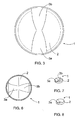
Figure 3 is a schematic top view of a second well bottom, -
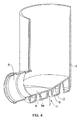
Figure 4 is a schematic view of the lower part of the well having a well bottom of a third embodiment, seen obliquely from above and cross cut, -
Figure 5 is a schematic view of the lower part of the well having a well bottom of a fourth embodiment, seen obliquely from above and cross cut, -
Figure 6 is a top view of the well bottom ofFigure 5 , -
Figure 7 is a schematic view of the well bottom ofFigure 5 , seen obliquely from above, and -
Figure 8 is a schematic view of the well bottom of a fifth embodiment, seen obliquely from above. - In the figures some embodiments of the invention have been presented in a simplified manner for the sake of clarity. Like reference numerals refer to like parts in the figures.
-
Figure 1 shows a well bottom 1. The well bottom 1 consists of aplate 2. Theplate 2 is designed such that the well bottom 1 comprises aflow channel 3a towards an outlet connection. Theplate 2 is further designed such that the well bottom 1 is funnel-like, i.e. in other parts except for theflow channel 3a theplate 2 is formed to slope towards the centre of the bottom 1. Theflow channel 3a is slightly inclined towards the outlet connection. InFigure 2 , the bottom 1 of the well is illustrated from above. - In the well bottom 1 of
Figure 3 theplate 2 is designed such that, in addition to theflow channel 3a arranged towards the outlet connection, the well bottom 1 comprises asecond flow channel 3b, which is arranged from the inlet connection towards the centre of the bottom 1. Except for thesecond flow channel 3b, the well bottom ofFigure 3 is similar to the well bottom ofFigures 1 and 2 . Thesecond flow channel 3b is slightly inclined towards the centre of the well bottom 1. - In connection with the well bottom of
Figures 1 and 2 , the inlet connections shall be arranged clearly, i.e. typically a few centimetres, higher up than the outlet connection. In the solution ofFigure 3 , one of the inlet connections need not be placed substantially higher up than the outlet connection. So, if the well is arranged in an even ground, it is not desirable for the sewer line to substantially lose in height in the well, i.e. to arrange the outlet connection substantially lower than the inlet connection, and therefore the solution ofFigure 3 is well applicable in cases like this. Thus, the solution ofFigure 3 may be the bottom of an inspection well, which only receives one inlet connection. The inlet connection and the outlet connection are arranged on the opposite sides of the well, whereby thefirst flow channel 3a and thesecond flow channel 3b are arranged in alignment, and consequently, in practice, one continuous flow channel runs through the bottom of the well. Hence the flow from the inlet channel is able to flow smoothly to the outlet connection. - In connection with the well bottom of
Figure 3 it is possible to arrange in the well also other inlet connections than the one for which theflow channel 3b is provided. In that case, the locations of these other inlet connections may be chosen relatively freely and they are arranged slightly higher up than the height level of the outlet connection, whereby the flow coming therefrom flows to the mid-section of the well bottom, thanks to the funnel-shaped bottom, and further through theflow channel 3a leading towards the outlet connection to the outlet connection. -
Figure 4 shows the lower part of the well 3. The well 3 may be a sewage well, in which the disclosed solutions are particularly useful, because smoothness of flowing is of utmost importance in the sewage wells. The disclosed solutions may also be used, for instance, in connection with drain wells or some other wells. Wells are used, for instance, when several inlet connections are to be joined to one outlet connection, i.e. for instance several inlet sewers to one outlet sewer. Further, wells are used for changing the direction of underground pipework. Wells are also used as inspection wells in direct pipelines. When the well is used as a drain well, it does not necessarily involve a single inlet connection. In that case water runs into the drain well through its cover or set of covers. - In the solution of
Figure 4 the well bottom 1 is attached to thewell wall 4. Attachment of the bottom 1 to thewall 4 may take place, for instance, by gluing or welding or by using some other suitable attachment method. Further, it is possible to provide the bottom and the wall of the well to be an integral structure, for instance, by means of die casting or rotational casting or by using some other solution producing an integral structure. Further,Figure 4 shows anoutlet connection 5, into which the flow from theflow channel 3a is directed. - In the solution of
Figure 4 , the bottom 1 also consists of a substantiallyhorizontal part 6 resting on the ground, in addition to thesloping plate 2 that provides flow. The lower face of thepart 6 resting on the ground is mainly even, whereby it fits closely against the ground below. Thepart 6 resting on the ground and theplate 2 are interconnected by means of side walls andconnection walls 7. It is also possible to use ribs or support poles or other corresponding structures for connecting thepart 6 resting on the ground and theplate 2. Theconnection walls 7 are formed such that anaperture 8 is provided in the middle thereof. In that case the bottom 1 is easy to manufacture, for instance, by rotational casting or blow moulding. Naturally, because of theapertures 8 thepart 6 resting on the ground is not completely even, but the proportion of theapertures 8 of the total surface area of the part resting on the ground is so small, however, that the surface is mainly even. Advantageously the proportion of theapertures 8 of the total surface area of the part resting on the ground is less than 40%, particularly advantageously less than 20%. - It is also possible to provide the bottom 1 such that the
plate 2 is formed to be a separate piece and thepart 6 resting on the ground is a separate piece, and these pieces are interconnected, for instance, by welding or gluing. In that case it is also possible to use injection moulding technique and nevertheless result in an even lower face of thepart 6 resting on the ground. - The solution of
Figure 5 corresponds, to a great extent, to the solution ofFigure 4 , but in the solution ofFigure 5 there is provided aflow channel 3b from the inlet connection towards the midsection of the well bottom, and an inlet connection 9 is mounted in the well 3. - Further, in
Figure 5 theplate 2 is formed in the vicinity of thechannel 3a leading to theoutlet connection 5 to be more sharply sloping close to the edge of the well 3 than close to the centre of the bottom 1. In other parts than in the vicinity of theoutlet connection 5 the slope angle of thesloping plate 2 remains substantially constant. - Said detail is illustrated by the different shapes of
flow channels Figure 6 and it also appears fromFigure 7 . - In the solution of
Figure 8 the bottom 1 comprises only aflow channel 3a leading towards the outlet connection. In the vicinity of thisflow channel 3a the sloping plate is also formed to be steeper close to the edge of the well than close to the centre of the well bottom 1. Also in this case the slope angle of thesloping plate 2 is substantially constant in all other parts except for in the vicinity of thechannel 3a. Typically, the inlet connections are arranged on the opposite side of the well with respect to the outlet connection, i.e. in the area of 180 degrees which is furthest away from the outlet connection and where, for instance in the case ofFigure 8 , the slope angle of thesloping plate 2 remains constant. - In some cases the features set forth in this application may be used as such, irrespective of other features. On the other hand, features set forth in this application may be combined, when necessary, to provide various combinations.
- The drawings and the relating specification are only intended to illustrate the inventive idea. The details of the invention may vary within the scope of the claims.
Claims (15)
- A well which includes a well bottom (1) and a wall (4) and at least one outlet connection (5) and in the bottom (1) of which well there is provided at least one flow channel (3a) at least for the outlet connection (5), characterized in that
the flow-forming part of the well bottom (1) consists of a plate (2) that is formed sloping towards the centre of the well bottom (1) in other parts except for the flow channel (3a). - The well of claim 1, characterized in that
the well bottom (1) consists of said sloping plate (2) and of a substantially horizontal part (6) resting on the ground, which part (6) resting on the ground is mainly even and whereby the sloping plate (2) and the part (6) resting on the ground together form the bottom (1) of the well. - The well of claim 2, characterized in that
the sloping plate (2) and the part (6) resting on the ground are formed to be an integral structure by means of rotational casting or blow moulding. - The well of any one of the preceding claims, characterized in that
the sloping plate (2) is steeper in the vicinity of the outlet connection (5) close to the edge of the well (3) than close to the midsection of the bottom (1) of the well (3). - The well of claim 4, characterized in that in other parts except for in the vicinity of the outlet connection (5) the slope angle of the sloping plate (2) remains substantially constant.
- The well of any one of the preceding claims, characterized in that
the well includes at least one inlet connection (9). - The well of claim 6, characterized in that in the plate (2) forming the bottom (1) of the well (3) there is provided a second flow channel (3b) from the direction of the inlet connection (9) towards the centre of the bottom (1) of the well (3).
- The well of claim 7, characterized in that
the flow channel (3a) leading towards the outlet connection (5) is aligned with the flow channel (3b) from the inlet connection (9) towards the centre of the bottom (1) of the well (3). - A well bottom which is provided with at least one flow channel (3a) at least for an outlet connection (5), characterized in that
the flow-forming part of the well bottom (1) consists of a plate (2) that is formed sloping towards the centre of the well bottom (1) in other parts except for the flow channel (3a). - The well bottom of claim 9, characterized in that
the well bottom (1) consists of said sloping plate (2) and of a substantially horizontal part (6) resting on the ground, which part resting on the ground (6) is mainly even and whereby the sloping plate (2) and the part (6) resting on the ground together form the bottom (1) of the well. - The well bottom of claim 10, characterized in that
the sloping plate (2) and the part (6) resting on the ground are formed to be an integral structure by means of rotational casting or blow moulding. - The well bottom of any one of claims 9 to 11, characterized in that
the sloping plate (2) is steeper in the vicinity of the outlet connection (5) close to the edge of the well (3) than close to the midsection of the bottom (1) of the well (3). - The well bottom of claim 12, characterized in that
in other parts except for in the vicinity of the outlet connection (5) the slope angle of the sloping plate (2) remains substantially constant. - The well bottom of any one of claims 9 to 13, characterized in that in the plate (2) forming the well bottom (1) there is provided a second flow channel (3b) from the direction of the inlet connection (9) towards the centre of the well bottom (1).
- The well bottom of claim 14, characterized in that
the flow channel (3a) leading towards the outlet connection (5) is aligned with the flow channel (3b) from the inlet connection (9) towards the centre of the bottom (1) of the well (3).
Applications Claiming Priority (1)
| Application Number | Priority Date | Filing Date | Title |
|---|---|---|---|
| FI20085267A FI20085267A7 (en) | 2008-04-01 | 2008-04-01 | Well and well bottom |
Publications (2)
| Publication Number | Publication Date |
|---|---|
| EP2107174A2 true EP2107174A2 (en) | 2009-10-07 |
| EP2107174A3 EP2107174A3 (en) | 2012-02-22 |
Family
ID=39385895
Family Applications (1)
| Application Number | Title | Priority Date | Filing Date |
|---|---|---|---|
| EP09156387A Withdrawn EP2107174A3 (en) | 2008-04-01 | 2009-03-27 | Well and well bottom |
Country Status (2)
| Country | Link |
|---|---|
| EP (1) | EP2107174A3 (en) |
| FI (1) | FI20085267A7 (en) |
Cited By (3)
| Publication number | Priority date | Publication date | Assignee | Title |
|---|---|---|---|---|
| DE102009037042A1 (en) * | 2009-08-13 | 2011-02-17 | Hegler Plastik Gmbh | Shaft, in particular a control and flushing shaft for wastewater with a flow channel and plate for a flow channel |
| CN103882934A (en) * | 2014-03-04 | 2014-06-25 | 上海优井环保科技有限公司 | Well seat of spiral steel belt inspection well |
| CN105839765A (en) * | 2016-05-17 | 2016-08-10 | 昆山市东部自来水管道安装有限公司 | Siamesed sewage well |
Citations (6)
| Publication number | Priority date | Publication date | Assignee | Title |
|---|---|---|---|---|
| GB1443052A (en) | 1973-01-04 | 1976-07-21 | Hepworth Iron Co Ltd | Inspection chambers |
| FI76159B (en) | 1985-06-05 | 1988-05-31 | Uponor Nv | BRUNN HELT AV PLAST. |
| US5413307A (en) * | 1993-11-22 | 1995-05-09 | The Concrete Company | Precast manhole invert forming |
| NL1000840C2 (en) | 1995-07-19 | 1997-01-21 | Waco Liesbosch Beton B V | Collection pit for sewers |
| WO2001096777A1 (en) | 2000-06-12 | 2001-12-20 | Uponor Innovation Ab | Well |
| WO2004007857A1 (en) | 2002-07-12 | 2004-01-22 | Uponor Innovation Ab | Well |
Family Cites Families (3)
| Publication number | Priority date | Publication date | Assignee | Title |
|---|---|---|---|---|
| NL145308B (en) * | 1965-01-29 | 1975-03-17 | W J Van De Kerke En Zoon Nv | INSPECTION SOCKET FOR A SEWERING PLANT. |
| DE4236193A1 (en) * | 1992-10-27 | 1994-04-28 | Willi Goebel | Underground-drain access shaft - is in plastic annular sections forming double wall filled with free-flowing and hardening material |
| NL1029091C2 (en) * | 2005-05-23 | 2006-11-30 | Dyka B V | Inspection pit. |
-
2008
- 2008-04-01 FI FI20085267A patent/FI20085267A7/en not_active Application Discontinuation
-
2009
- 2009-03-27 EP EP09156387A patent/EP2107174A3/en not_active Withdrawn
Patent Citations (6)
| Publication number | Priority date | Publication date | Assignee | Title |
|---|---|---|---|---|
| GB1443052A (en) | 1973-01-04 | 1976-07-21 | Hepworth Iron Co Ltd | Inspection chambers |
| FI76159B (en) | 1985-06-05 | 1988-05-31 | Uponor Nv | BRUNN HELT AV PLAST. |
| US5413307A (en) * | 1993-11-22 | 1995-05-09 | The Concrete Company | Precast manhole invert forming |
| NL1000840C2 (en) | 1995-07-19 | 1997-01-21 | Waco Liesbosch Beton B V | Collection pit for sewers |
| WO2001096777A1 (en) | 2000-06-12 | 2001-12-20 | Uponor Innovation Ab | Well |
| WO2004007857A1 (en) | 2002-07-12 | 2004-01-22 | Uponor Innovation Ab | Well |
Cited By (4)
| Publication number | Priority date | Publication date | Assignee | Title |
|---|---|---|---|---|
| DE102009037042A1 (en) * | 2009-08-13 | 2011-02-17 | Hegler Plastik Gmbh | Shaft, in particular a control and flushing shaft for wastewater with a flow channel and plate for a flow channel |
| CN103882934A (en) * | 2014-03-04 | 2014-06-25 | 上海优井环保科技有限公司 | Well seat of spiral steel belt inspection well |
| CN103882934B (en) * | 2014-03-04 | 2016-05-04 | 上海道程环保科技有限公司 | The well seat of helical steel band inspection shaft |
| CN105839765A (en) * | 2016-05-17 | 2016-08-10 | 昆山市东部自来水管道安装有限公司 | Siamesed sewage well |
Also Published As
| Publication number | Publication date |
|---|---|
| FI20085267L (en) | 2009-10-02 |
| EP2107174A3 (en) | 2012-02-22 |
| FI20085267A0 (en) | 2008-04-01 |
| FI20085267A7 (en) | 2009-10-02 |
Similar Documents
| Publication | Publication Date | Title |
|---|---|---|
| JP2019143381A (en) | Rainwater drainage system | |
| EP2759647B1 (en) | Drain | |
| JP2008248614A (en) | Drainage structure for bathroom | |
| JP2015105486A (en) | Catch basin | |
| JP2016003548A (en) | Drainage structure and catchment basin | |
| JP5117043B2 (en) | Rainwater flow facilitator for vertical pipes | |
| JP5669974B1 (en) | Drain | |
| JP2016176330A (en) | Gutter system | |
| EP2884016B1 (en) | Drain with siphon | |
| JP5457889B2 (en) | Rainwater drainage system and method for installing rainwater drainage system | |
| JP4927508B2 (en) | Siphon drainage system | |
| EP1540098B1 (en) | Well | |
| KR20130070173A (en) | Valve room | |
| JP4317514B2 (en) | Rainwater splash prevention device in relay drain | |
| KR101967854B1 (en) | Structure of Drainage Trench | |
| JP2002317487A (en) | Water diversion unit | |
| EP1992747A3 (en) | Overflow pit with adjustable channel | |
| AU2001100525A4 (en) | Manhole base section | |
| JP2004278099A (en) | Drainage structure of drainage pipe and drainage joint | |
| JP5285938B2 (en) | Drainage hopper for water heater | |
| KR200405377Y1 (en) | manhole | |
| JP2007014209A (en) | Underdrain drainage device | |
| JP4395418B2 (en) | Drainage equipment | |
| JP2024157833A (en) | Underground drainage device and underground drainage structure | |
| KR200403878Y1 (en) | the bace block with inverter for prefabricated manhole |
Legal Events
| Date | Code | Title | Description |
|---|---|---|---|
| PUAI | Public reference made under article 153(3) epc to a published international application that has entered the european phase |
Free format text: ORIGINAL CODE: 0009012 |
|
| AK | Designated contracting states |
Kind code of ref document: A2 Designated state(s): AT BE BG CH CY CZ DE DK EE ES FI FR GB GR HR HU IE IS IT LI LT LU LV MC MK MT NL NO PL PT RO SE SI SK TR |
|
| AX | Request for extension of the european patent |
Extension state: AL BA RS |
|
| PUAL | Search report despatched |
Free format text: ORIGINAL CODE: 0009013 |
|
| AK | Designated contracting states |
Kind code of ref document: A3 Designated state(s): AT BE BG CH CY CZ DE DK EE ES FI FR GB GR HR HU IE IS IT LI LT LU LV MC MK MT NL NO PL PT RO SE SI SK TR |
|
| AX | Request for extension of the european patent |
Extension state: AL BA RS |
|
| RIC1 | Information provided on ipc code assigned before grant |
Ipc: E03F 5/02 20060101AFI20120113BHEP |
|
| 17P | Request for examination filed |
Effective date: 20120326 |
|
| AKX | Designation fees paid |
Designated state(s): AT BE BG CH CY CZ DE DK EE ES FI FR GB GR HR HU IE IS IT LI LT LU LV MC MK MT NL NO PL PT RO SE SI SK TR |
|
| 17Q | First examination report despatched |
Effective date: 20121127 |
|
| RAP1 | Party data changed (applicant data changed or rights of an application transferred) |
Owner name: UPONOR INNOVATION AB |
|
| RAP1 | Party data changed (applicant data changed or rights of an application transferred) |
Owner name: UPONOR INFRA OY |
|
| STAA | Information on the status of an ep patent application or granted ep patent |
Free format text: STATUS: THE APPLICATION HAS BEEN WITHDRAWN |
|
| 18W | Application withdrawn |
Effective date: 20160209 |